EP4527655A1 - Hybrid power system and hybrid vehicle with same - Google Patents
Hybrid power system and hybrid vehicle with same Download PDFInfo
- Publication number
- EP4527655A1 EP4527655A1 EP22949094.1A EP22949094A EP4527655A1 EP 4527655 A1 EP4527655 A1 EP 4527655A1 EP 22949094 A EP22949094 A EP 22949094A EP 4527655 A1 EP4527655 A1 EP 4527655A1
- Authority
- EP
- European Patent Office
- Prior art keywords
- motor
- clutch
- output shaft
- engine
- power
- Prior art date
- Legal status (The legal status is an assumption and is not a legal conclusion. Google has not performed a legal analysis and makes no representation as to the accuracy of the status listed.)
- Pending
Links
Images





Classifications
-
- B—PERFORMING OPERATIONS; TRANSPORTING
- B60—VEHICLES IN GENERAL
- B60K—ARRANGEMENT OR MOUNTING OF PROPULSION UNITS OR OF TRANSMISSIONS IN VEHICLES; ARRANGEMENT OR MOUNTING OF PLURAL DIVERSE PRIME-MOVERS IN VEHICLES; AUXILIARY DRIVES FOR VEHICLES; INSTRUMENTATION OR DASHBOARDS FOR VEHICLES; ARRANGEMENTS IN CONNECTION WITH COOLING, AIR INTAKE, GAS EXHAUST OR FUEL SUPPLY OF PROPULSION UNITS IN VEHICLES
- B60K6/00—Arrangement or mounting of plural diverse prime-movers for mutual or common propulsion, e.g. hybrid propulsion systems comprising electric motors and internal combustion engines
- B60K6/20—Arrangement or mounting of plural diverse prime-movers for mutual or common propulsion, e.g. hybrid propulsion systems comprising electric motors and internal combustion engines the prime-movers consisting of electric motors and internal combustion engines, e.g. HEVs
- B60K6/22—Arrangement or mounting of plural diverse prime-movers for mutual or common propulsion, e.g. hybrid propulsion systems comprising electric motors and internal combustion engines the prime-movers consisting of electric motors and internal combustion engines, e.g. HEVs characterised by apparatus, components or means specially adapted for HEVs
- B60K6/38—Arrangement or mounting of plural diverse prime-movers for mutual or common propulsion, e.g. hybrid propulsion systems comprising electric motors and internal combustion engines the prime-movers consisting of electric motors and internal combustion engines, e.g. HEVs characterised by apparatus, components or means specially adapted for HEVs characterised by the driveline clutches
- B60K6/387—Actuated clutches, i.e. clutches engaged or disengaged by electric, hydraulic or mechanical actuating means
-
- B—PERFORMING OPERATIONS; TRANSPORTING
- B60—VEHICLES IN GENERAL
- B60K—ARRANGEMENT OR MOUNTING OF PROPULSION UNITS OR OF TRANSMISSIONS IN VEHICLES; ARRANGEMENT OR MOUNTING OF PLURAL DIVERSE PRIME-MOVERS IN VEHICLES; AUXILIARY DRIVES FOR VEHICLES; INSTRUMENTATION OR DASHBOARDS FOR VEHICLES; ARRANGEMENTS IN CONNECTION WITH COOLING, AIR INTAKE, GAS EXHAUST OR FUEL SUPPLY OF PROPULSION UNITS IN VEHICLES
- B60K6/00—Arrangement or mounting of plural diverse prime-movers for mutual or common propulsion, e.g. hybrid propulsion systems comprising electric motors and internal combustion engines
- B60K6/20—Arrangement or mounting of plural diverse prime-movers for mutual or common propulsion, e.g. hybrid propulsion systems comprising electric motors and internal combustion engines the prime-movers consisting of electric motors and internal combustion engines, e.g. HEVs
- B60K6/22—Arrangement or mounting of plural diverse prime-movers for mutual or common propulsion, e.g. hybrid propulsion systems comprising electric motors and internal combustion engines the prime-movers consisting of electric motors and internal combustion engines, e.g. HEVs characterised by apparatus, components or means specially adapted for HEVs
- B60K6/24—Arrangement or mounting of plural diverse prime-movers for mutual or common propulsion, e.g. hybrid propulsion systems comprising electric motors and internal combustion engines the prime-movers consisting of electric motors and internal combustion engines, e.g. HEVs characterised by apparatus, components or means specially adapted for HEVs characterised by the combustion engines
-
- B—PERFORMING OPERATIONS; TRANSPORTING
- B60—VEHICLES IN GENERAL
- B60K—ARRANGEMENT OR MOUNTING OF PROPULSION UNITS OR OF TRANSMISSIONS IN VEHICLES; ARRANGEMENT OR MOUNTING OF PLURAL DIVERSE PRIME-MOVERS IN VEHICLES; AUXILIARY DRIVES FOR VEHICLES; INSTRUMENTATION OR DASHBOARDS FOR VEHICLES; ARRANGEMENTS IN CONNECTION WITH COOLING, AIR INTAKE, GAS EXHAUST OR FUEL SUPPLY OF PROPULSION UNITS IN VEHICLES
- B60K6/00—Arrangement or mounting of plural diverse prime-movers for mutual or common propulsion, e.g. hybrid propulsion systems comprising electric motors and internal combustion engines
- B60K6/20—Arrangement or mounting of plural diverse prime-movers for mutual or common propulsion, e.g. hybrid propulsion systems comprising electric motors and internal combustion engines the prime-movers consisting of electric motors and internal combustion engines, e.g. HEVs
- B60K6/22—Arrangement or mounting of plural diverse prime-movers for mutual or common propulsion, e.g. hybrid propulsion systems comprising electric motors and internal combustion engines the prime-movers consisting of electric motors and internal combustion engines, e.g. HEVs characterised by apparatus, components or means specially adapted for HEVs
- B60K6/26—Arrangement or mounting of plural diverse prime-movers for mutual or common propulsion, e.g. hybrid propulsion systems comprising electric motors and internal combustion engines the prime-movers consisting of electric motors and internal combustion engines, e.g. HEVs characterised by apparatus, components or means specially adapted for HEVs characterised by the motors or the generators
-
- B—PERFORMING OPERATIONS; TRANSPORTING
- B60—VEHICLES IN GENERAL
- B60K—ARRANGEMENT OR MOUNTING OF PROPULSION UNITS OR OF TRANSMISSIONS IN VEHICLES; ARRANGEMENT OR MOUNTING OF PLURAL DIVERSE PRIME-MOVERS IN VEHICLES; AUXILIARY DRIVES FOR VEHICLES; INSTRUMENTATION OR DASHBOARDS FOR VEHICLES; ARRANGEMENTS IN CONNECTION WITH COOLING, AIR INTAKE, GAS EXHAUST OR FUEL SUPPLY OF PROPULSION UNITS IN VEHICLES
- B60K6/00—Arrangement or mounting of plural diverse prime-movers for mutual or common propulsion, e.g. hybrid propulsion systems comprising electric motors and internal combustion engines
- B60K6/20—Arrangement or mounting of plural diverse prime-movers for mutual or common propulsion, e.g. hybrid propulsion systems comprising electric motors and internal combustion engines the prime-movers consisting of electric motors and internal combustion engines, e.g. HEVs
- B60K6/22—Arrangement or mounting of plural diverse prime-movers for mutual or common propulsion, e.g. hybrid propulsion systems comprising electric motors and internal combustion engines the prime-movers consisting of electric motors and internal combustion engines, e.g. HEVs characterised by apparatus, components or means specially adapted for HEVs
- B60K6/38—Arrangement or mounting of plural diverse prime-movers for mutual or common propulsion, e.g. hybrid propulsion systems comprising electric motors and internal combustion engines the prime-movers consisting of electric motors and internal combustion engines, e.g. HEVs characterised by apparatus, components or means specially adapted for HEVs characterised by the driveline clutches
-
- B—PERFORMING OPERATIONS; TRANSPORTING
- B60—VEHICLES IN GENERAL
- B60K—ARRANGEMENT OR MOUNTING OF PROPULSION UNITS OR OF TRANSMISSIONS IN VEHICLES; ARRANGEMENT OR MOUNTING OF PLURAL DIVERSE PRIME-MOVERS IN VEHICLES; AUXILIARY DRIVES FOR VEHICLES; INSTRUMENTATION OR DASHBOARDS FOR VEHICLES; ARRANGEMENTS IN CONNECTION WITH COOLING, AIR INTAKE, GAS EXHAUST OR FUEL SUPPLY OF PROPULSION UNITS IN VEHICLES
- B60K6/00—Arrangement or mounting of plural diverse prime-movers for mutual or common propulsion, e.g. hybrid propulsion systems comprising electric motors and internal combustion engines
- B60K6/20—Arrangement or mounting of plural diverse prime-movers for mutual or common propulsion, e.g. hybrid propulsion systems comprising electric motors and internal combustion engines the prime-movers consisting of electric motors and internal combustion engines, e.g. HEVs
- B60K6/22—Arrangement or mounting of plural diverse prime-movers for mutual or common propulsion, e.g. hybrid propulsion systems comprising electric motors and internal combustion engines the prime-movers consisting of electric motors and internal combustion engines, e.g. HEVs characterised by apparatus, components or means specially adapted for HEVs
- B60K6/40—Arrangement or mounting of plural diverse prime-movers for mutual or common propulsion, e.g. hybrid propulsion systems comprising electric motors and internal combustion engines the prime-movers consisting of electric motors and internal combustion engines, e.g. HEVs characterised by apparatus, components or means specially adapted for HEVs characterised by the assembly or relative disposition of components
-
- B—PERFORMING OPERATIONS; TRANSPORTING
- B60—VEHICLES IN GENERAL
- B60K—ARRANGEMENT OR MOUNTING OF PROPULSION UNITS OR OF TRANSMISSIONS IN VEHICLES; ARRANGEMENT OR MOUNTING OF PLURAL DIVERSE PRIME-MOVERS IN VEHICLES; AUXILIARY DRIVES FOR VEHICLES; INSTRUMENTATION OR DASHBOARDS FOR VEHICLES; ARRANGEMENTS IN CONNECTION WITH COOLING, AIR INTAKE, GAS EXHAUST OR FUEL SUPPLY OF PROPULSION UNITS IN VEHICLES
- B60K6/00—Arrangement or mounting of plural diverse prime-movers for mutual or common propulsion, e.g. hybrid propulsion systems comprising electric motors and internal combustion engines
- B60K6/20—Arrangement or mounting of plural diverse prime-movers for mutual or common propulsion, e.g. hybrid propulsion systems comprising electric motors and internal combustion engines the prime-movers consisting of electric motors and internal combustion engines, e.g. HEVs
- B60K6/22—Arrangement or mounting of plural diverse prime-movers for mutual or common propulsion, e.g. hybrid propulsion systems comprising electric motors and internal combustion engines the prime-movers consisting of electric motors and internal combustion engines, e.g. HEVs characterised by apparatus, components or means specially adapted for HEVs
- B60K6/40—Arrangement or mounting of plural diverse prime-movers for mutual or common propulsion, e.g. hybrid propulsion systems comprising electric motors and internal combustion engines the prime-movers consisting of electric motors and internal combustion engines, e.g. HEVs characterised by apparatus, components or means specially adapted for HEVs characterised by the assembly or relative disposition of components
- B60K6/405—Housings
-
- B—PERFORMING OPERATIONS; TRANSPORTING
- B60—VEHICLES IN GENERAL
- B60K—ARRANGEMENT OR MOUNTING OF PROPULSION UNITS OR OF TRANSMISSIONS IN VEHICLES; ARRANGEMENT OR MOUNTING OF PLURAL DIVERSE PRIME-MOVERS IN VEHICLES; AUXILIARY DRIVES FOR VEHICLES; INSTRUMENTATION OR DASHBOARDS FOR VEHICLES; ARRANGEMENTS IN CONNECTION WITH COOLING, AIR INTAKE, GAS EXHAUST OR FUEL SUPPLY OF PROPULSION UNITS IN VEHICLES
- B60K6/00—Arrangement or mounting of plural diverse prime-movers for mutual or common propulsion, e.g. hybrid propulsion systems comprising electric motors and internal combustion engines
- B60K6/20—Arrangement or mounting of plural diverse prime-movers for mutual or common propulsion, e.g. hybrid propulsion systems comprising electric motors and internal combustion engines the prime-movers consisting of electric motors and internal combustion engines, e.g. HEVs
- B60K6/42—Arrangement or mounting of plural diverse prime-movers for mutual or common propulsion, e.g. hybrid propulsion systems comprising electric motors and internal combustion engines the prime-movers consisting of electric motors and internal combustion engines, e.g. HEVs characterised by the architecture of the hybrid electric vehicle
- B60K6/44—Series-parallel type
- B60K6/442—Series-parallel switching type
-
- Y—GENERAL TAGGING OF NEW TECHNOLOGICAL DEVELOPMENTS; GENERAL TAGGING OF CROSS-SECTIONAL TECHNOLOGIES SPANNING OVER SEVERAL SECTIONS OF THE IPC; TECHNICAL SUBJECTS COVERED BY FORMER USPC CROSS-REFERENCE ART COLLECTIONS [XRACs] AND DIGESTS
- Y02—TECHNOLOGIES OR APPLICATIONS FOR MITIGATION OR ADAPTATION AGAINST CLIMATE CHANGE
- Y02T—CLIMATE CHANGE MITIGATION TECHNOLOGIES RELATED TO TRANSPORTATION
- Y02T10/00—Road transport of goods or passengers
- Y02T10/60—Other road transportation technologies with climate change mitigation effect
- Y02T10/62—Hybrid vehicles
Definitions
- the present disclosure relates to the field of vehicle technologies, and in particular, relates to a hybrid power system and a hybrid electric vehicle equipped with the same.
- Hybrid electric vehicles have gradually gained the favor of the market due to superior energy saving and emission reduction and excellent user experience. Accordingly, demands for the hybrid power system are ever increasing on the market. Mainstream vehicle manufacturers are actively developing hybrid power systems, especially integrated development of dedicated hybrid power transmissions. However, most hybrid power transmissions on the market have low integration, large size, and complex structure, which are not conducive to vehicle layout.
- Embodiments of the present disclosure provide a hybrid power system and a hybrid electric vehicle equipped with the same.
- the technical solutions are as follows.
- a hybrid power system in one aspect of the present disclosure, includes: a first clutch, a second clutch, an engine, a first motor, a second motor, and a power output assembly; wherein two ends of the first clutch are respectively connected to the first motor and the engine; two ends of the second clutch are respectively connected to the first clutch and the power output assembly; and the second motor is connected to the power output assembly; wherein the first clutch and the second clutch are disposed in a radial direction of an output shaft of the first motor, and the second clutch is disposed on a side, away from the output shaft of the first motor, of the first clutch.
- the first clutch includes a first portion and a second portion, wherein the first portion and the second portion are controllably engaged or disengaged; and the second clutch includes a third portion and a fourth portion, wherein the third portion and the fourth portion are controllably engaged or disengaged; wherein the second portion of the first clutch is connected to the third portion of the second clutch.
- the second portion and the third portion are integrally connected.
- the first portion is sleeved on an output shaft of the engine, and one end of the second portion is sleeved on the output shaft of the first motor, and the other end of the second portion is disposed on a side, away from the output shaft of the engine, of the first portion and is engaged with the first portion; and the third portion is sleeved on the other end of the second portion, one end of the fourth portion is connected to the power output assembly, and the other end of the fourth portion is disposed on a side, away from the second portion, of the third portion and is engaged with the third portion.
- the output shaft of the first motor is a step shaft, wherein a diameter of a shaft head of the step shaft is less than a diameter of a shaft body of the step shaft, and the second portion is connected to the shaft head, such that at least part of the second portion is accommodated in an annular space surrounding the shaft head.
- the first portion is an inner hub of the first clutch
- the second portion is an outer hub of the first clutch
- the third portion is an inner hub of the second clutch
- the fourth portion is an outer hub of the second clutch
- the outer hub of the first clutch and the inner hub of the second clutch are formed by respectively machining splines on an inner wall and an outer wall of a same hub sleeve.
- the splines on the inner wall of the same hub sleeve and the splines on the outer wall of the same hub sleeve are arranged in an opposing staggered configuration.
- the power output assembly includes a hollow shaft, wherein the hollow shaft is sleeved on an output shaft of the engine and is rotatable relative to the output shaft of the engine; a length of the hollow shaft is less than a length of the output shaft of the engine, such that an end of the output shaft of the engine protrudes from the hollow shaft and is connected to the first portion; and the fourth portion is connected to the hollow shaft.
- an output shaft of the first motor and an output shaft of the engine are coaxial and close to each other, and a gap is present between the output shaft of the first motor and the output shaft of the engine, wherein the gap is inside the first clutch and the second clutch.
- an axis of an output shaft of the second motor is parallel to an axis of the output shaft of the first motor, and a length of the output shaft of the second motor is greater than a length of the output shaft of the first motor.
- an overlapped region is present between an orthographic projection of the power output assembly on a first plane, an orthographic projection of the output shaft of the engine on the first plane, and an orthographic projection of the output shaft of the second motor on the first plane; and a space is present between the orthographic projection of the power output assembly on the first plane and an orthographic projection of the output shaft of the first motor on the first plane; wherein the first plane is a plane that runs through the axis of the output shaft of the first motor and is perpendicular to a vertical line between the axis of the output shaft of the second motor and an axis of the output shaft of the engine.
- the hybrid power system further includes: a housing; wherein the first motor, the second motor, the first clutch, and the second clutch are all disposed inside the housing, and an arrangement direction of the first motor and the second motor inside the housing is perpendicular to an axis of the output shaft of the first motor; and the engine is disposed outside the housing, and an output shaft of the engine includes a power output of the engine and a connection shaft detachably connected to the power output of the engine, wherein the connection shaft is disposed inside the housing and is rotatable relative to the housing, and part of the connection shaft protrudes from the housing.
- a hybrid electric vehicle in another aspect of the present disclosure, includes the above hybrid power system.
- the hybrid power system is mostly developed based on the traditional automatic transmission, and is formed by simply integrating a motor in a front or back end of the transmission, such as an automatic transmission (AT), an automated mechanical transmission (AMT), a continuously variable transmission (CVT), or a dual clutch transmission (DCT).
- AT automatic transmission
- AMT automated mechanical transmission
- CVT continuously variable transmission
- DCT dual clutch transmission
- hybrid power system is widely used by many vehicle companies due to low research cost and low technical threshold.
- the hybrid power system has the following obvious disadvantages.
- the traditional hybrid transmission does not have an extended range mode, such that after combination, only a few operating modes are supported, and thus the fuel saving effect is poor.
- Some embodiments of the present disclosure provide a hybrid power system to improve the above defects of the hybrid power system in some practices.
- the hybrid power system has high integration and compact structure, such that layout space is greatly saved; the engine and wheels are decoupled, such that the impact generated in switching modes is avoided; and the hybrid power system supports a plurality of operating modes to meet different operating requirements in different operation situations, such that the fuel saving effect is improved.
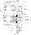
- the hybrid power system includes a first clutch 1, a second clutch 2, an engine 3 (not shown in the drawings), a first motor 4, a second motor 5, and a power output assembly 6.
- Two ends of the first clutch 1 are respectively connected to the first motor 4 and the engine 3, two ends of the second clutch 2 are respectively connected to the first clutch 1 and the power output assembly 6, and the second motor 5 is connected to the power output assembly 6.
- the first clutch 1 and the second clutch 2 are disposed in a radial direction of an output shaft 41 of the first motor 4, and the second clutch 2 is disposed on a side, away from the output shaft 41 of the first motor 4, of the first clutch 1.
- first clutch 1 and the second clutch 2 being disposed in the radial direction of the output shaft 41 of the first motor 4 means that an arrangement direction of the first clutch 1 and the second clutch 2 is perpendicular to an axis of the output shaft 41 of the first motor 4.
- the first clutch 1 and the second clutch 2 are sequentially disposed on a side of the output shaft 41 of the first motor 4, and in this case, the second clutch 2 is disposed on a side, away from the output shaft 41 of the first motor 4, of the first clutch; or, the first clutch 1 and the second clutch 2 are sleeved on the output shaft 41 of the first motor 4, and in this case, the first clutch surrounds a periphery of the output shaft 41 of the first motor 4, and the second clutch surrounds a periphery of the first clutch.
- the axial arrangement space is saved, and the system structure is more compact.
- the engine 3 and the first motor 4 are respectively connected to the two ends of the first clutch 1, and power is transmitted through connection and cooperation between the first clutch 1 and the second clutch 2, such that the system integration is high.
- the engine 3 is decoupled from the wheels through the first clutch 1 and the second clutch 2 to avoid the impact in switching modes.
- the first clutch 1 includes a first portion 11 and a second portion 12.
- the first portion 11 and the second portion 12 are controllably engaged or disengaged.
- the second clutch 2 includes a third portion 21 and a fourth portion 22.
- the third portion 21 and the fourth portion 22 are controllably engaged or disengaged.
- the second portion 12 of the first clutch 1 is connected to the third portion 21 of the second clutch 2. As the second portion is directly connected to the third portion, the integration and structure compactness of the system are further improved.
- the second portion 12 and the third portion 21 are integrally connected.
- the second portion 12 of the first clutch 1 and the third portion 21 of the second clutch 2 are integrally connected, such that the two clutches are assembled conveniently, and the assembling process and the cost are reduced.
- the two clutches only have three clutch hubs, the structure after assembling the two clutches is more compact and has strong linkage.
- the integrated structure of the second portion 12 and the third portion 21 is acquired by stamping manufacturing, or by processing using machine tools after manufacturing.
- the first portion 11 is sleeved on an output shaft 31 of the engine 3, and one end of the second portion 12 is sleeved on the output shaft 41 of the first motor 4, and the other end of the second portion 12 is disposed on a side, away from the output shaft 31 of the engine 3, of the first portion 11 and is engaged with the first portion 11.
- the third portion 21 is sleeved on the other end of the second portion 12, and one end of the fourth portion 22 is connected to the power output assembly 6, and the other end of the fourth portion 22 is disposed on a side, away from the second portion 12, of the third portion 21 and is engaged with the third portion 21.
- the first portion 11 is fixedly connected to a shaft wall of the output shaft 31 of the engine 3, and thus is rotatable under driving of the output shaft 31 of the engine 3.
- the second portion 12 is fixedly connected to a shaft wall of the output shaft 41 of the first motor 4, and thus is rotatable under driving of the output shaft 41 of the first motor 4.
- the third portion 21 of the second clutch 2 is connected to or disposed on an end, away from the first motor 4, of the second portion 12 to avoid failure caused by stress concentration at the end of the second portion 12 connected to the output shaft 41 of the first motor 4.
- the first portion 11 is an inner hub of the first clutch 1
- the second portion 12 is an outer hub of the first clutch 1
- the third portion 21 is an inner hub of the second clutch 2
- the fourth portion 22 is an outer hub of the second clutch 2
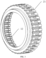
- the outer hub of the first clutch 1 and the inner hub of the second clutch 2 are formed by respectively machining splines on an inner wall and an outer wall of a same hub sleeve.
- the hub sleeve refers to a cylindrical clutch hub, and is generally sleeved outside the power shaft in the assembling process, for example, sleeved outside the output shaft 41 of the first motor 4 in the embodiments of the present disclosure.
- the inner wall and the outer wall of the hub sleeve are respectively provided with toothed splines.
- the spline parameters of the inner wall of the hub sleeve are different from the spline parameters of the outer wall of the hub sleeve.
- the toothed parameters of the inner hub of the first clutch 1 are matched with the spline parameters of the inner wall of the hub sleeve, and the toothed parameters of the outer hub of the second clutch 2 are matched with the spline parameters of the outer wall of the hub sleeve.
- the first clutch 1 and the second clutch 2 are friction clutches.
- a plurality pf pieces of corresponding clutch plates are respectively disposed in the first portion 11 and the second portion 12 of the first clutch 1, a plurality of pieces of corresponding clutch plates are respectively disposed in the third portion 21 and the fourth portion 22 of the second clutch 2.
- the two portions of each clutch achieve rotation speed synchronization based on mutual friction between the clutch plates.
- splines on the inner wall of the same hub sleeve and splines on the outer wall of the same hub sleeve are arranged in an opposing staggered configuration to ensure the strength of the hub sleeve.
- a protruded portion of the spline on the inner wall of the hub sleeve corresponds to a recessed portion of the spline on the outer wall of the hub sleeve
- a recessed portion of the spline on the inner wall of the hub sleeve corresponds to a protruded portion of the spline on the outer wall of the hub sleeve.
- the splines on the inner wall of the hub sleeve and the splines on the outer wall of the hub sleeve are trapezoidal splines.
- the trapezoidal splines are formed by stamping process, which is simple and easy to manufacture.
- the first motor 4 may include a stator and a rotor.
- the stator refers to a fixed portion of the first motor 4, and for example, is provided with a pair of direct current excited stationary main magnetic poles; and the rotor is an iron core running from the inside of the stator, and, for example, is provided with an armature winding, which generates an induced electromotive force when powered up to rotate relative to the stator under the action of excitation.
- part of the rotor protrudes from the inside of the stator to form an output shaft, or part of the rotor protrudes from the inside of the stator and is connected to a connection shaft to form an output shaft; and the hub sleeve is fixedly connected to the output shaft.
- the fixed connection mode includes screw, welding, and the like. Therefore, in the case that the rotor of the first motor 4 rotates, the hub sleeve synchronously rotates with the rotor.
- An arrangement space is reserved between the splined portion on the hub sleeve and the output shaft 41 of the first motor 4 to facilitate arrangement of the inner hub of the first clutch 1. That is, the inner hub of the first clutch 1 is disposed in the space.
- the output shaft 41 of the first motor 4 is a step shaft.
- a diameter of a shaft head of the step shaft is less than a diameter of a shaft body of the step shaft.
- the shaft head refers to an end portion, away from the stator, of the rotor of the first motor 4.
- the second portion 12 is connected to the shaft head, such that at least part of the second portion 12 is accommodated in an annular space surrounding the shaft head.
- the structure of the step shaft means that a notch is defined in the end portion, away from the stator, of the rotor along the circumference, and part of the first clutch 1 is disposed in the notch.
- the radial space is saved, such that the arrangement of the first clutch 1 and the output shaft 41 of the first motor 4 is more compact.
- the term "radial” herein refers to a radial direction of the output shaft 41 of the first motor 4.
- the power output assembly 6 includes a hollow shaft 61.
- the hollow shaft 61 is sleeved on an output shaft 31 of the engine 3 and is rotatable relative to the output shaft 31 of the engine 3.
- a length of the hollow shaft 61 is less than a length of the output shaft 31 of the engine 3, such that an end of the output shaft 31 of the engine 3 protrudes from the hollow shaft 61 and is connected to the first portion 11.
- the fourth portion 22 is connected to the hollow shaft 61.
- the hollow shaft 61 is rotatable freely relative to the output shaft 31 of the engine 3.
- a bearing is disposed between the hollow shaft 61 and the output shaft 31 of the engine 3, and the hollow shaft 61 and the output shaft 31 of the engine 3 are connected through the bearing to rotate relative to each other.
- the output shaft 31 of the engine 3 protrudes from a cylinder cover of the engine 3.
- the output shaft 31 of the engine 3 is a crankshaft, or the output shaft 31 of the engine 3 includes a crankshaft and a connection shaft connected to the crankshaft.
- the hollow shaft 61 is sleeved on a portion of the output shaft that protrudes from the cylinder cover of the engine 3, and the length of hollow shaft 61 is less than a length of the protruded portion, such that the end portion of the output shaft 31 of the engine 3 protrudes from the hollow shaft 61.
- the end portion of the output shaft 31 of the engine 3 that protrudes from the hollow shaft 61 is fixedly connected to the first portion 11 of the first motor 4.
- the fixed connection mode includes screw, welding, and the like. Therefore, in the case that the output shaft 31 of the engine 3 rotates, the first portion 11 synchronously rotates with the output shaft 31.
- the power output assembly 6 further includes a first gear 62 affixed on the hollow shaft 61, an intermediate shaft 63, and a second gear 64 and a third gear 65 affixed on the intermediate shaft 63.
- the first gear 62 synchronously rotates with the hollow shaft 61
- the second gear 64 synchronously rotates with the intermediate shaft 63
- the first gear 62 is engaged with the second gear 64.
- the power is sequentially transmitted through the hollow shaft 61, the first gear 62, the second gear 64, and the intermediate shaft 63, and the intermediate shaft 63 continues to output the power backward.
- the fourth portion 22 of the second clutch 2 is fixedly connected to the hollow shaft 61.
- the fourth portion 22 synchronously rotates.
- the power at the hub sleeve is transmitted through the second clutch 2 to a power output assembly 6 direction, or is transmitted through the power output assembly 6 and the second clutch 2 to a hub sleeve direction.
- the fixed connection mode between the fourth portion 22 and the hollow shaft 61 includes screw, welding, and the like.
- the second gear 64 is further engaged with a motor output gear 52 on the output shaft 51 of the second motor 5, and thus the power output by the second motor 5 is transmitted through the motor output gear 52, the second gear 64, and the intermediate shaft 63 in sequence to achieve power transmission.
- an output shaft 41 of the first motor 4 and an output shaft 31 of the engine 3 are coaxial and close to each other, and a gap is present between the output shaft 41 of the first motor 4 and the output shaft 31 of the engine 3.
- the gap is inside the first clutch 1 and the second clutch 2.
- the output shaft 41 of the first motor 4 and the output shaft 31 of the engine 3 are coaxial and close to each other, such that a power transmission path between the two power sources is short, and the power loss is less.
- the first motor 4 acts as a starter for the engine 3.
- the starting of the engine 3 needs external support.
- a starter is configured for the engine 3, and a flywheel of the engine 3 is driven, by the starter, to rotate, such that the engine 3 is started.
- the engine 3 is driven, by the first motor 4, to start, and thus the first motor 4 acts as the starter.
- no starter is disposed in the hybrid power system, and the structure is simplified.
- the first clutch 1 is controlled to be engaged, the second clutch 2 is controlled to be disengaged, and the first motor is controlled to operate.
- the power output by the first motor 4 is transmitted to the output shaft 31 of the engine 3 after traveling through the output shaft 41 of the first motor 4, the second portion 12 of the first clutch 1, and the first portion 11 of the first clutch 1 to drive the engine 3 to start.
- the first motor 4 assists in stopping the engine 3 and adjusting the speed of the engine 3. In the case that the first motor 4 assists in starting and accelerating the engine 3, the first motor 4 converts electric energy into mechanical energy to output the power. In the case that the first motor 4 assists in stopping or decelerating the engine 3, the first motor 4 converts the mechanical energy output by the engine 3 into electric energy and store the electric energy for use.
- the first motor 4 is not configured to assist in starting the engine 3, and a separate starter is disposed for the engine 3.
- a gap is present between an end portion of the output shaft 41 of the first motor 4 close to the output shaft 31 of the engine 3 and an end portion of the output shaft 31 of the engine 3 close to the output shaft 41 of the first motor 4, that is, the end portions are not in contact with each other.
- the gap is a minimum distance between the engine 3 and the first motor 4, which is not too large, otherwise an axial layout space is wasted.
- the term "axial" herein refers to an axis direction of the output axis 41 of the first motor 4.
- a maximum of the gap is not greater than a size of the first clutch 1 and a size of the second clutch 2. That is, the gap is in the first clutch 1 and the second clutch 2. The smaller the gap, the more compact the arrangement of the system.
- the output shaft jitters, and thus the gap should not be too small to ensure that the engine 3 and the first motor 4 are not affected by each other whether in separate rotation or in simultaneous rotation.
- an axis of the output shaft 51 of the second motor 5 is parallel to an axis of the output shaft 41 of the first motor 4, and a length of the output shaft 51 of the second motor 5 is greater than a length of the output shaft 41 of the first motor 4.
- An arrangement direction of the second motor 5 is the same as that of the first motor 4 and the engine 3.
- the axis of the output shaft 51 of the second motor 5 is parallel to the axis of the output shaft 41 of the first motor 4 and the axis of the output shaft 31 of the engine 3 to ensure the full and reasonable utilization of the layout space.
- the output shafts of the three power sources are parallel to each other, the direction change in the transmission of power is reduced, such that the power loss is reduced, and the power transmission efficiency is improved.
- the second motor 5 may also include a stator and a rotor. As shown in FIG. 1 , part of the rotor protrudes from the inside of the stator to form an output shaft, or part of the rotor protrudes from the inside of the stator and is connected to a connection shaft to form the output shaft 51 of the second motor 5.
- the length of the output shaft 51 of the second motor 5 is greater than the length of the output shaft 41 of the first motor 4, such that the output shaft 51 of the second motor 5 includes a corresponding portion of the output shaft 41 of the first motor 4 and a corresponding portion of the output shaft 31 of the engine 3, such that the path for power transmission is shortened, a number of other power transmission assemblies, such as the gear and the intermediate shaft 63, is reduced, and the loss in the power transmission process is reduced.
- an overlapped region is present between an orthographic projection of the power output assembly 6 on a first plane, an orthographic projection of the output shaft 31 of the engine 3 on the first plane, and an orthographic projection of the output shaft 51 of the second motor 5 on the first plane, and a space is present between the orthographic projection of the power output assembly 6 on the first plane and an orthographic projection of the output shaft 41 of the first motor 4 on the first plane.
- the first plane is a plane that runs through the axis of the output shaft 41 of the first motor 4 and is perpendicular to a vertical line between the axis of the output shaft 51 of the second motor 5 and an axis of the output shaft 31 of the engine 3.
- the first plane is also referred to as an overlapping plane.
- the power output assembly 6 is actually disposed between the output shaft 31 of the engine 3 and the output shaft 51 of the second motor 5. Specifically, the power output assembly 6 is disposed between the output shaft 31 of the engine 3 and a portion, corresponding to the output shaft 31 of the engine 3, of the output shaft 51 of the second motor 5.
- the overlapped region is present between the orthographic projection of the power output assembly 6 on the first plane, the orthographic projection of the output shaft 31 of the engine 3 on the first plane, and the orthographic projection of the output shaft 51 of the second motor 5 on the first plane, and the orthographic projection of the power output assembly 6 on the first plane, the orthographic projection of the output shaft 31 of the engine 3 on the first plane, and the orthographic projection of the output shaft 51 of the second motor 5 on the first plane are not overlapped with the orthographic projection of the output shaft 41 of the first motor 4 on the first plane. Therefore, the use of the layout space in the system is more reasonable and balanced, most of the assemblies are not disposed in a region to cause distribution imbalance, and thus the space is not wasted.
- the first plane is a plane that runs through the axis of the output shaft 41 of the first motor 4 and is perpendicular to a section shown in FIG. 1 .
- the system further includes a housing 8.
- the first motor 4, the second motor 5, the first clutch 1, and the second clutch 2 are all disposed inside the housing 8, and an arrangement direction of the first motor 4 and the second motor 5 inside the housing 8 is perpendicular to an axis of the output shaft 41 of the first motor 4.
- the engine 3 is disposed outside the housing 8, and an output shaft 31 of the engine 3 includes a power output of the engine 3 and a connection shaft 311 detachably connected to the power output of the engine 3.
- the connection shaft 311 is disposed inside the housing 8 and is rotatable relative to the housing 8, and part of the connection shaft 311 protrudes from the housing 8.
- a volume of the first motor 4 and a volume of the second motor 5 are small, and a volume of the engine 3 is large.
- the first motor 4, the second motor 5, the first clutch 1, the second clutch 2, the power output assembly 6, and the connection shaft 311 are disposed inside the housing 8 to facilitate assembling, and the engine 3 is independent of the housing 8.
- the engine 3 has a power output, and the power output is, for example, a crankshaft.
- the crankshaft is connected to the connection shaft 311 to form the output shaft 31 of the engine 3.
- connection mode may be, for example, screw connection, clamp connection, and the like.
- the hybrid power system further includes a wheel drive assembly 7.
- the wheel drive assembly 7 includes a differential 71, a wheel drive shaft, and two wheels.
- the differential 71 is disposed on the wheel drive shaft, and the gears of the differential 71 are engaged with the third gear 65 on the intermediate shaft 63 of the power output assembly 6 to receive power output by the power output assembly 6.
- the two wheels are disposed on two ends of the wheel drive shaft, and the differential 71 enables the two wheels to rotate at different speeds for fine steering.
- the power output by the power output assembly 6 is transmitted to the two wheels through the third gear 65, the differential 71, and the wheel drive shaft in sequence.
- the hybrid power system further includes a power assembly.
- the first motor 4 and the second motor 5 exchange energy with the power supply assembly.
- the power supply assembly provides energy to the operating motor; and in the case that the first motor 4 and/or the second motor 5 are in a power generation mode, the power supply assembly receives and stores energy converted by the motor which is generating the power.
- the motor being "operating” means that the motor is in a state of converting electric energy into mechanical energy
- the motor being “not operating” means that the motor is in a state of neither converting electric energy into mechanical energy nor converting mechanical energy into electric energy
- the motor being "in the power generation mode” means that the motor is in a state of converting mechanical energy into electric energy.
- the first motor 4 and the second motor 5 can rotate forwards or reversely. The vehicle forwards in the case that the vehicle rotates forwards, and the reversing function of the vehicle is started in the case that the vehicle rotates reversely.
- the power assembly further includes a power set, a first motor 4 microcontroller unit (MCU1), and a second motor 5 microcontroller unit, a first inverter, and a second inverter.
- the power set is connected to the first inverter and the second inverter, the first motor 4 microcontroller unit and the first motor 4 are electrically connected to the first inverter, and the second motor 5 microcontroller unit and the second motor 5 are electrically connected to the second inverter.
- the power supply assembly includes a battery management system capable of monitoring the usage status of the battery set at all times, alleviating inconsistencies of the battery set through necessary measures, and providing security for the use of the battery set.
- the hybrid power system is equipped with three power sources: the engine 3, the first motor 4, and the second motor 5.
- the three power sources are driven separately or jointly, and are combined with the first clutch 1, the second clutch 2, and the two different power transmission paths corresponding to the power output component 6 to output power in a plurality of operating modes and a plurality of levels to drive the wheels to rotate, such that the fuel saving effect is improved.
- the first clutch 1 and the second clutch 2 in the embodiments of the present disclosure are an integrated structure connected to each other, based on an arrangement and assembly mode determined based on the structural features of various assemblies, the whole system has the high integration, the compact structure, and the balanced and reasonable space utilization.
- the engine 3 can be decoupled from the wheel through the first clutch 1 and the second clutch 2, the impact in switching modes is avoided, and the driving comfort is improved.
- the hybrid power system includes a first clutch 1, a second clutch 2, an engine 3, a first motor 4, a second motor 5, and a power output assembly 6.
- the first clutch 1 and the second clutch 2 are disposed in a radial direction of an output shaft of the first motor 4.
- the first clutch 1 includes a first portion 11 and a second portion 12 that are controllably engaged or disengaged.
- the first portion 11 is connected to an output shaft of the engine 3, and the second portion 12 is connected to the output shaft of the first motor 4.
- the second clutch 2 includes a third portion 21 and a fourth portion 22 that are controllably engaged or disengaged.
- the third portion 21 is connected to the second portion 12 and is disposed on a side, away from the first motor 4, of the second portion 12, and the fourth portion 22 is connected to the power output assembly 6.
- An output shaft of the second motor 5 is connected to the power output assembly 6.
- the second portion 12 and the third portion 21 are integrally connected.
- an output shaft of the first motor 4 and an output shaft of the engine 3 are coaxial and close to each other, and a gap is present between the output shaft of the first motor 4 and the output shaft of the engine 3.
- the gap is inside the first clutch 1 and the second clutch 2.
- an axis of the output shaft of the second motor 5 is parallel to an axis of the output shaft of the first motor 4, and a length of the output shaft of the second motor 5 is greater than a length of the output shaft of the first motor 4.
- an overlapped region is present between an orthographic projection of the power output assembly 6 on a first plane, an orthographic projection of the output shaft of the engine 3 on the first plane, and an orthographic projection of the output shaft of the second motor 5 on the first plane, and a space is present between the orthographic projection of the power output assembly 6 on the first plane and an orthographic projection of the output shaft of the first motor 4 on the first plane.
- the first plane runs through the axis of the output shaft of the first motor 4 and is perpendicular to a vertical line between the axis of the output shaft of the second motor 5 and an axis of the output shaft of the engine 3.
- the system further includes a housing 8.
- the first motor 4, the second motor 5, the first clutch 1, and the second clutch 2 are all disposed inside the housing 8, and an arrangement direction of the first motor 4 and the second motor 5 inside the housing 8 is perpendicular to an axis of the output shaft of the first motor 4.
- the engine 3 is disposed outside the housing 8, and an output shaft of the engine 3 includes a power output of the engine 3 and a connection shaft 311 detachably connected to the power output of the engine 3. Part of the connection shaft 311 protrudes from the housing 8.
- the axial arrangement space is saved, and the system structure is more compact.
- the engine 3 and the first motor 4 are respectively connected to the first portion 11 and the second portion 12 of the first clutch 1, and power is transmitted through connection and cooperation between the first clutch 1 and the second clutch 2, such that the system integration is high.
- the engine 3 is decoupled from the wheels through the first clutch 1 and the second clutch 2 to avoid the impact in switching modes. Based on the three power sources of the engine 3, the first motor 4, and the second motor 5 and the two control devices of the first clutch 1 and the second clutch 2, a plurality of operating modes are acquired to improve the fuel saving effect.
- the hybrid electric vehicle includes the hybrid power system according to any of the above embodiments.
- the vehicle further includes a controller that can determine a matching operating mode based on the current vehicle state and control the hybrid power system to switch to the corresponding operating mode.
- the current vehicle state includes at least current accelerator pedal opening, current brake pedal opening, a current power battery amount, a current speed, and a current operating situation.
- the operating modes that can be realized by the hybrid power system at least include a first pure electric driving mode, a second pure electric driving mode, a first hybrid driving mode, a second hybrid driving mode, an engine direct driving mode, an energy recovery mode, and a stationary power generation mode.
- the second motor 5 acts as a separate power source.
- the operating mode is generally applicable to the situation where the vehicle is in low-speed creep or in a cruising state, for example, an urban situation, such that the power consumption in the process of congestion and parking and waiting is reduced, and more power is saved.
- requirements of economy, power, comfort and the like of the user are met.
- the controller is configured to: control the second motor 5 to operate, control the engine 3 and the first motor 4 not to operate, and control the first clutch 1 and the second clutch 2 to be disengaged.
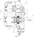
- the direct current output by the power battery is converted into the three-phase alternating current through the second inverter to drive the output shaft 51 of the second motor 5 to rotate, and the power output by the second motor 5 is directly transmitted to the power output assembly 6.
- the first transmission path of power between the power output assembly 6 and the wheel drive assembly 7 is that the second gear 64 rotates after receiving the power transmitted by the motor output gear 52 on the output shaft 51 of the second motor 5 and drives the intermediate shaft 63 and the third gear 65 to rotate, and the power is then transmitted to the drive shaft after traveling through the gear of the differential 71 engaged with the third gear 65 and transmitted to the wheel to drive the vehicle.
- the second motor 5 forwards in the case that the vehicle rotates forwards, and the reversing function of the vehicle is started in the case that the vehicle rotates reversely.
- the first motor 4 is not separately used to drive the vehicle generally. However, in some cases, for example, the failure of the second motor 5, the first motor 4 is separately used to drive the vehicle.
- the controller is configured to: control the first motor 4 to operate, control the engine 3 and the second motor 5 not to operate, control the first clutch 1 to be disengaged, and control the second clutch 2 to be engaged.
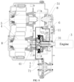
- the transmission path is that the direct current output by the power battery is converted into the three-phase alternating current through the first inverter to drive the output shaft 41 of the first motor 4 to rotate, and the power output by the first motor 4 is transmitted to the power output assembly 6 after traveling through the engaged second clutch 2.
- the second transmission path of power between the power output assembly 6 and the wheel drive assembly 7 is that the hollow shaft 61 rotates after receiving the power transmitted by the second clutch 2 and drives the first gear 62 affixed on the hollow shaft 61 to rotate, and the power is transmitted to the intermediate shaft 63 after traveling through the second gear 64 engaged with the first gear 62 to cause the intermediate shaft 63 and the third gear 65 to synchronously rotate, transmitted to the drive shaft after traveling through the gear of the differential 71 engaged with the third gear 65, and then transmitted to the wheel to drive the vehicle.
- the first motor 4 and the second motor 5 act as a joint power source to drive the vehicle.
- the dual-motor driving is generally applicable to a scenario where the user needs to keep the vehicle at a low speed state and temporarily needs a large torque, for example an overtaking scenario, a starting scenario, and the like, such that the vehicle acquires a large torque in a short time and has a good dynamic response.
- the controller is configured to: control the first motor 4 and the second motor 5 to operate, control the engine 3 not to operate, control the first clutch 1 to be disengaged, and control the second clutch 2 to be engaged.
- the direct current output by the power battery is converted into the three-phase alternating current through the first inverter and the second inverter to drive the first motor 4 and the output shaft 51 of the second motor 5 to rotate.
- the power output by the first motor 4 is transmitted to the power output assembly 6 after traveling through the second clutch 2, the power output by the second motor 5 is directly transmitted to the power output assembly 6, and the power is converged at the second gear 64 in the power output assembly 6 and transmitted to the wheel drive assembly 7.
- the power transmission paths of power output by the first motor 4 and the second motor 5 are described in the above embodiments, which are not repeated herein.
- the first hybrid driving mode in the embodiments of the present disclosure is also referred to as a serial/range extended hybrid driving mode.
- the engine 3 and the second motor 5 act as a mixed power source.
- the first motor 4 acts as a power generation device, and the operating mode is generally applicable to a high torque situation and a rapid acceleration situation, for example, a scenario where the vehicle is at a high speed state and temporarily needs a large torque to overtake, such that the power advantage of the engine 3 at the high speed and the fast response of the motor are used.
- the operating mode is also applicable to a scenario where the electricity amount of the power battery is insufficient, the first motor 4 generates power to supply the power for the second motor 5 to drive the vehicle.
- the controller in the case that the vehicle is in the first hybrid driving mode, is configured to: control the engine 3 and the second motor 5 to operate, control the first motor 4 to be in a power generation mode, control the first clutch 1 to be engaged, and control the second clutch 2 to be disengaged.
- FIG. 6 shows a power transmission path in the case that the vehicle drives the vehicle in a first hybrid driving mode.
- the engine 3 operates in an efficient zone to drive the first motor 4 to generate power, and the generated electric energy is converted by the first inverter and the second inverter and transmitted to the second motor 5 for the second motor 5 to drive the vehicle.
- the excess electric energy is stored in the power battery in response the excess electric energy.
- the power battery replenishes the electricity amount, such that the first motor 4 and the power battery jointly meet the electricity demand of the second motor 5.
- the power transmission path is that the power output by the output shaft 31 of the engine 3 is transmitted to the first motor 4 after traveling through the engaged first cultch 1.
- the power transmission path of power output by the second motor 5 to the wheel end is described in the above embodiments, which is not repeated herein.
- the engine 3 is decoupled to the differential 71 and the wheel, and only drives the first motor 4 to rotate.
- the wheel end is not affected in switching modes, and the driving comfort is improved.
- the engine 3 has a great fuel saving effect and a high economy.
- the first hybrid driving mode in the embodiments of the present disclosure is also referred to as a parallel hybrid driving mode.
- the engine 3 and at least one motor act as power sources. That is, at least two power sources operate jointly to drive the vehicle.
- the variable transmission system outputs a large power to improve the power performance of the vehicle, which is generally applicable to a large torque situation, a rapid acceleration situation, and a situation of the insufficient electricity amount of the power battery.
- the power sources include the following two cases based on a number of power sources.
- the engine 3 and the second motor 5 act as a joint power source.
- the controller is configured to: control the engine 3 to operate, control the first motor 4 not to operate or in a power generation mode, control the second motor 5 to operate, and control the first clutch 1 and the second clutch 2 to be engaged.
- the engine 3 operates in an efficient zone to output power.
- part of power output by the engine 3 is configured to drive the first motor to generate electricity, and the generated electricity is transmitted to the second motor 5 after being converted by the first inverter and the second inverter for the second motor 5 to drive the vehicle.
- Part of power is directly used to drive the vehicle.
- part of the power output by the engine 3 drags the output shaft 41 of the first motor 4 to rotate and thus is lost, and part of the power is used to directly drive the vehicle.
- the excess electric energy is stored in the power battery in response the excess electric energy.
- the power battery replenishes the electricity amount, such that the first motor 4 and the power battery jointly meet the electricity demand of the second motor 5.
- the power transmission path is that the power is transmitted by the output shaft 31 of the engine 3 to the connected first cultch 1, is transmitted to the second clutch 2 after traveling through the engaged first cultch 1, and is transmitted to the power output assembly 6 and the wheel drive assembly 7 after traveling through the second clutch 2.
- Part of the power output by the engine 3 for driving the vehicle is converged at the second gear 64 with the power output by the second motor 5, which are transmitted backwards.
- the power transmission path of the power between the power output assembly 6 and the vehicle drive assembly are described in the above embodiments, which are not repeated herein.
- the engine 3, the first motor 4, and the second motor 5 act as a joint power source.
- the controller is configured to: control the engine 3, the first motor 4, and the second motor 5 to operate, and control the first clutch 1 and the second clutch 2 to be engaged.
- FIG. 7 shows a power transmission path in the case that the vehicle jointly drives the vehicle using three power sources.
- the engine 3 operates in an efficient zone to output power, the power battery outputs the direct current, and the direct current is converted into the three-phase alternating current through the first inverter and the second inverter to drive the first motor and the output shaft 51 of the second motor 5 to rotate.
- the power transmission paths are described in the above embodiments, which are not repeated herein.
- Part of the power output by the engine 3 for driving the vehicle is converged with the power output by the first motor 4 at the first clutch 1 (in fact, the second portion 12 of the first clutch 1) , and then the converged power and the power output by the second motor 5 are further converged at the power output assembly 6 to be transmitted backwards.
- the power transmission path of the power between the power output assembly 6 and the vehicle drive assembly are described in the above embodiments, which are not repeated herein.
- the engine 3 acts as a separate power source.
- the operating mode is generally applicable to a scenario where the variable transmission system occurs high voltage failure, a situation of the insufficient electricity amount of the battery, and a high speed situation. In this case, the power consumption is great in driving by the motor, and the power consumption is reduced in the case that the engine 3 is directly used to drive.
- the controller in the case that the vehicle is controlled to be in the engine direct driving mode, is configured to: control the engine 3 to operate, control the first motor 4 to selectively be in a power generation mode according to the demand of the electricity amount, control the second motor 5 not to operate, and control the first clutch 1 and the second clutch 2 to be engaged.
- FIG. 8 shows a power transmission path in the case that the vehicle drives the vehicle in an engine direct driving mode.
- the transmission path of the power output by the engine 3 is the same as the transmission path of the power in driving by the engine 3 in the second hybrid driving mode, which are described in the above embodiments and thus are not repeated herein.
- the first motor 4 in the case that the power battery does not need charge, the first motor 4 is controlled not to operate. In this case, part of the power output by the engine 3 drags the output shaft 41 of the first motor 4 to rotate and thus is lost, and part of the power is used to directly drive the vehicle.
- variable transmission system in a taxiing/braking energy recovery mode
- at least one of the first motor 4 and the second motor 5 acts as a power generation device to convert the kinetic energy of the vehicle into the electric energy and store the electric energy in the power battery for backup.
- the operating mode is generally applicable to a taxiing situation and a braking situation, and the vehicle recovers part of the kinetic energy and convert the kinetic energy into the electric energy for storage to provide energy for the subsequent operation of the vehicle, such that the available range of the vehicle is improved.
- the controller is configured to: control the second motor 5 to be in a power generation mode, control the engine 3 and the first motor 4 not to operate, and control the first clutch 1 and the second clutch 2 to be disengaged.
- the reverse torque output by the wheel is transmitted to the second motor 5 after traveling through the drive shaft, the gear of the differential 71, the third gear 65, the intermediate shaft 63, the second gear 64, the motor output gear 52, and the output shaft 51 of the second motor 5 in sequence, and the second motor 5 converts the part of braked kinetic energy into the electric energy and stores the electric energy in the power battery for backup.
- the power transmission path in this mode is exactly opposite to the power transmission path in driving the vehicle by the second motor 5 in the first pure electric driving mode.
- the controller is configured to: control the engine 3 to operate, control the first motor 4 and the second motor 5 to be in a power generation mode, control the first clutch 1 to be engaged, and control the second clutch 2 to be disengaged.
- the reverse torque output by the wheel is transmitted to the second motor 5 over the same power transmission path as shown in FIG. 9 , and the second motor 5 converts the part of braked kinetic energy into the electric energy and stores the electric energy in the power battery for backup.
- the power output by the engine 3 is transmitted to the first motor 4 after traveling through the engaged first clutch 1, and the first motor 4 converts the part of the mechanical energy into the electric energy and stores the electric energy in the power battery for backup.
- the stationary power generation mode is generally applicable to a situation of the insufficient electricity amount of the batter, and the power battery is charged by the power output by the engine 3.
- the controller in the case that the vehicle is controlled to be in the stationary power generation mode, the controller is configured to: control the engine 3 to operate, control the first motor 4 to be in a power generation mode, control the second motor 5 not to operate, control the first clutch 1 to be engaged, and control the second clutch 2 to be disengaged.
- FIG. 10 shows a power transmission path in the case that the vehicle drives the vehicle in a first hybrid driving mode.
- the transmission path of the power output by the engine 3 is the same as the power transmission path in energy recovery by the engine 3 using the first motor 4 in the stationary power generation mode, which are described in the above embodiments and thus are not repeated herein.
- the hybrid power variable transmission system includes three power sources, that is, two motors and an engine, to ensure the great power performance of the vehicle.
- the high-performance dual-motor ensures sufficient power of the vehicle in the normal driving process, and provides a great low-speed torque when the vehicle accelerates rapidly.
- the engine ensures that the vehicle has excellent acceleration performance across the entire speed range and provides sufficient backup power after the speed increases.
- the hybrid power variable transmission system has excellent economy.
- the high-performance dual-motor cooperates to meet most of the performance requirements of the vehicle, such that the operating time of the engine is greatly reduced, the fuel consumption and emissions are reduced.
- the two motors selectively operate to ensure that the motor operates in a good efficiency zone.
- the hybrid power variable transmission system has a long available range and does not suffer from range anxiety of the electric vehicle.
- the hybrid power variable transmission system is configured to be in an engine drive mode in the long distance driving process to ensure the excellent driving comfort and the available range in corporation with the optimized three-speed gear ratios.
Landscapes
- Engineering & Computer Science (AREA)
- Chemical & Material Sciences (AREA)
- Combustion & Propulsion (AREA)
- Transportation (AREA)
- Mechanical Engineering (AREA)
- Hybrid Electric Vehicles (AREA)
- Arrangement Of Transmissions (AREA)
Abstract
Description
- This application claims priority to
Chinese Patent Application No. 202210753220.6, filed on June 28, 2022 - The present disclosure relates to the field of vehicle technologies, and in particular, relates to a hybrid power system and a hybrid electric vehicle equipped with the same.
- With popularity of vehicles, vehicle exhaust emissions have become a primary source of urban air pollution. Thus, more and more new energy vehicles have entered the consumer market to reduce impacts of fuel vehicle exhaust emissions on the environment.
- Hybrid electric vehicles have gradually gained the favor of the market due to superior energy saving and emission reduction and excellent user experience. Accordingly, demands for the hybrid power system are ever increasing on the market. Mainstream vehicle manufacturers are actively developing hybrid power systems, especially integrated development of dedicated hybrid power transmissions. However, most hybrid power transmissions on the market have low integration, large size, and complex structure, which are not conducive to vehicle layout.
- Embodiments of the present disclosure provide a hybrid power system and a hybrid electric vehicle equipped with the same. The technical solutions are as follows.
- In one aspect of the present disclosure, a hybrid power system is provided. The hybrid power system includes: a first clutch, a second clutch, an engine, a first motor, a second motor, and a power output assembly; wherein two ends of the first clutch are respectively connected to the first motor and the engine; two ends of the second clutch are respectively connected to the first clutch and the power output assembly; and the second motor is connected to the power output assembly; wherein the first clutch and the second clutch are disposed in a radial direction of an output shaft of the first motor, and the second clutch is disposed on a side, away from the output shaft of the first motor, of the first clutch.
- In some embodiments, the first clutch includes a first portion and a second portion, wherein the first portion and the second portion are controllably engaged or disengaged; and the second clutch includes a third portion and a fourth portion, wherein the third portion and the fourth portion are controllably engaged or disengaged; wherein the second portion of the first clutch is connected to the third portion of the second clutch.
- In some embodiments, the second portion and the third portion are integrally connected.
- In some embodiments, the first portion is sleeved on an output shaft of the engine, and one end of the second portion is sleeved on the output shaft of the first motor, and the other end of the second portion is disposed on a side, away from the output shaft of the engine, of the first portion and is engaged with the first portion; and the third portion is sleeved on the other end of the second portion, one end of the fourth portion is connected to the power output assembly, and the other end of the fourth portion is disposed on a side, away from the second portion, of the third portion and is engaged with the third portion.
- In some embodiments, the output shaft of the first motor is a step shaft, wherein a diameter of a shaft head of the step shaft is less than a diameter of a shaft body of the step shaft, and the second portion is connected to the shaft head, such that at least part of the second portion is accommodated in an annular space surrounding the shaft head.
- In some embodiments, the first portion is an inner hub of the first clutch, and the second portion is an outer hub of the first clutch; the third portion is an inner hub of the second clutch, and the fourth portion is an outer hub of the second clutch; wherein the outer hub of the first clutch and the inner hub of the second clutch are formed by respectively machining splines on an inner wall and an outer wall of a same hub sleeve.
- In some embodiments, the splines on the inner wall of the same hub sleeve and the splines on the outer wall of the same hub sleeve are arranged in an opposing staggered configuration.
- In some embodiments, the power output assembly includes a hollow shaft, wherein the hollow shaft is sleeved on an output shaft of the engine and is rotatable relative to the output shaft of the engine; a length of the hollow shaft is less than a length of the output shaft of the engine, such that an end of the output shaft of the engine protrudes from the hollow shaft and is connected to the first portion; and the fourth portion is connected to the hollow shaft.
- In some embodiments, an output shaft of the first motor and an output shaft of the engine are coaxial and close to each other, and a gap is present between the output shaft of the first motor and the output shaft of the engine, wherein the gap is inside the first clutch and the second clutch.
- In some embodiments, an axis of an output shaft of the second motor is parallel to an axis of the output shaft of the first motor, and a length of the output shaft of the second motor is greater than a length of the output shaft of the first motor.
- In some embodiments, an overlapped region is present between an orthographic projection of the power output assembly on a first plane, an orthographic projection of the output shaft of the engine on the first plane, and an orthographic projection of the output shaft of the second motor on the first plane; and a space is present between the orthographic projection of the power output assembly on the first plane and an orthographic projection of the output shaft of the first motor on the first plane; wherein the first plane is a plane that runs through the axis of the output shaft of the first motor and is perpendicular to a vertical line between the axis of the output shaft of the second motor and an axis of the output shaft of the engine.
- In some embodiments, the hybrid power system further includes: a housing; wherein the first motor, the second motor, the first clutch, and the second clutch are all disposed inside the housing, and an arrangement direction of the first motor and the second motor inside the housing is perpendicular to an axis of the output shaft of the first motor; and the engine is disposed outside the housing, and an output shaft of the engine includes a power output of the engine and a connection shaft detachably connected to the power output of the engine, wherein the connection shaft is disposed inside the housing and is rotatable relative to the housing, and part of the connection shaft protrudes from the housing.
- In another aspect of the present disclosure, a hybrid electric vehicle is provided. The hybrid electric vehicle includes the above hybrid power system.
- For clearer descriptions of the technical solutions according to the embodiments of the present disclosure, the following briefly introduces the accompanying drawings required for describing the embodiments. Apparently, the accompanying drawings in the following description show merely some embodiments of the present disclosure, and persons of ordinary skill in the art may still derive other drawings from these accompanying drawings without creative efforts.
-
FIG. 1 is a local section view of a hybrid power system according to some embodiments of the present disclosure; -
FIG. 2 is an enlarged diagram of a position A inFIG. 1 ; -
FIG. 3 is a schematic structural diagram of a hub sleeve according to some embodiments of the present disclosure; -
FIG. 4 is a schematic diagram of power transmission in a first pure electric driving mode; -
FIG. 5 is a schematic diagram of power transmission in a second pure electric driving mode; -
FIG. 6 is a schematic diagram of power transmission in a first hybrid driving mode; -
FIG. 7 is a schematic diagram of power transmission in joint driving of three power sources in a second hybrid driving mode; -
FIG. 8 is a schematic diagram of power transmission in an engine direct driving mode; -
FIG. 9 is a schematic diagram of power transmission in an energy recovery mode where in the case of an engine without power output; and -
FIG. 10 is a schematic diagram of power transmission in a stationary power generation mode. - Detailed embodiments of the present disclosure are shown by the above accompanying drawings, and more detailed description are shown hereinafter. These drawings and descriptions are not intended to limit the scope of the concept of the present disclosure in any way, but rather to illustrate the conception of the present disclosure for those skilled in the art by specific embodiments.
- The technical solutions according to the embodiments of the present disclosure are described clearly and completely hereinafter in combination with the accompanying drawings in the embodiments of the present disclosure. It is obvious that the described embodiments are merely part but not all of the embodiments of the present disclosure. All other embodiments derived by those skilled in the art without creative efforts based on the embodiments in the present disclosure are within the protection scope of the disclosure.
- In some practices, the hybrid power system is mostly developed based on the traditional automatic transmission, and is formed by simply integrating a motor in a front or back end of the transmission, such as an automatic transmission (AT), an automated mechanical transmission (AMT), a continuously variable transmission (CVT), or a dual clutch transmission (DCT).
- Such type of hybrid power system is widely used by many vehicle companies due to low research cost and low technical threshold. However, the hybrid power system has the following obvious disadvantages. First, the system integration is low, and the assembly size is large, which are not conducive to spatial layout and affect expansion of the power of the motor and the overall power performance of the vehicle. Second, in the case that the engine is started by the motor, the engine and wheels are not decoupled, such that an impact is generated in switching modes, and the driving comfort is affected; and in the case that the engine is started by the traditional starter, the starting time is long, and the starting noise is loud. Third, the traditional hybrid transmission does not have an extended range mode, such that after combination, only a few operating modes are supported, and thus the fuel saving effect is poor.
- Some embodiments of the present disclosure provide a hybrid power system to improve the above defects of the hybrid power system in some practices. The hybrid power system has high integration and compact structure, such that layout space is greatly saved; the engine and wheels are decoupled, such that the impact generated in switching modes is avoided; and the hybrid power system supports a plurality of operating modes to meet different operating requirements in different operation situations, such that the fuel saving effect is improved.
- As shown in
FIG. 1 andFIG. 2 , the hybrid power system according to the embodiments of the present disclosure includes afirst clutch 1, asecond clutch 2, an engine 3 (not shown in the drawings), afirst motor 4, a second motor 5, and apower output assembly 6. Two ends of thefirst clutch 1 are respectively connected to thefirst motor 4 and theengine 3, two ends of thesecond clutch 2 are respectively connected to thefirst clutch 1 and thepower output assembly 6, and the second motor 5 is connected to thepower output assembly 6. Thefirst clutch 1 and thesecond clutch 2 are disposed in a radial direction of anoutput shaft 41 of thefirst motor 4, and thesecond clutch 2 is disposed on a side, away from theoutput shaft 41 of thefirst motor 4, of thefirst clutch 1. - It should be noted that in the embodiments of the present disclosure, the
first clutch 1 and thesecond clutch 2 being disposed in the radial direction of theoutput shaft 41 of thefirst motor 4 means that an arrangement direction of thefirst clutch 1 and thesecond clutch 2 is perpendicular to an axis of theoutput shaft 41 of thefirst motor 4. Illustratively, thefirst clutch 1 and thesecond clutch 2 are sequentially disposed on a side of theoutput shaft 41 of thefirst motor 4, and in this case, thesecond clutch 2 is disposed on a side, away from theoutput shaft 41 of thefirst motor 4, of the first clutch; or, thefirst clutch 1 and thesecond clutch 2 are sleeved on theoutput shaft 41 of thefirst motor 4, and in this case, the first clutch surrounds a periphery of theoutput shaft 41 of thefirst motor 4, and the second clutch surrounds a periphery of the first clutch. - In the embodiments of the present disclosure, as the
first clutch 1 and thesecond clutch 2 are disposed in the radial direction of theoutput shaft 41 of thefirst motor 4, the axial arrangement space is saved, and the system structure is more compact. Theengine 3 and thefirst motor 4 are respectively connected to the two ends of thefirst clutch 1, and power is transmitted through connection and cooperation between thefirst clutch 1 and thesecond clutch 2, such that the system integration is high. Theengine 3 is decoupled from the wheels through thefirst clutch 1 and thesecond clutch 2 to avoid the impact in switching modes. Based on the three power sources, that is, theengine 3, thefirst motor 4, and the second motor 5 and the two control devices, that is, thefirst clutch 1 and thesecond clutch 2, a plurality of operating modes are supported, such that the fuel saving effect is improved. In some embodiments of the present disclosure, as shown inFIG. 2 , thefirst clutch 1 includes afirst portion 11 and asecond portion 12. Thefirst portion 11 and thesecond portion 12 are controllably engaged or disengaged. Thesecond clutch 2 includes athird portion 21 and afourth portion 22. Thethird portion 21 and thefourth portion 22 are controllably engaged or disengaged. Thesecond portion 12 of thefirst clutch 1 is connected to thethird portion 21 of thesecond clutch 2. As the second portion is directly connected to the third portion, the integration and structure compactness of the system are further improved. - In some embodiments, the
second portion 12 and thethird portion 21 are integrally connected. Thesecond portion 12 of thefirst clutch 1 and thethird portion 21 of thesecond clutch 2 are integrally connected, such that the two clutches are assembled conveniently, and the assembling process and the cost are reduced. In addition, as the two clutches only have three clutch hubs, the structure after assembling the two clutches is more compact and has strong linkage. - In the embodiments of the present disclosure, the integrated structure of the
second portion 12 and thethird portion 21 is acquired by stamping manufacturing, or by processing using machine tools after manufacturing. - In some embodiments of the present disclosure, as shown in
FIG. 1 andFIG. 2 , thefirst portion 11 is sleeved on anoutput shaft 31 of theengine 3, and one end of thesecond portion 12 is sleeved on theoutput shaft 41 of thefirst motor 4, and the other end of thesecond portion 12 is disposed on a side, away from theoutput shaft 31 of theengine 3, of thefirst portion 11 and is engaged with thefirst portion 11. Thethird portion 21 is sleeved on the other end of thesecond portion 12, and one end of thefourth portion 22 is connected to thepower output assembly 6, and the other end of thefourth portion 22 is disposed on a side, away from thesecond portion 12, of thethird portion 21 and is engaged with thethird portion 21. - The
first portion 11 is fixedly connected to a shaft wall of theoutput shaft 31 of theengine 3, and thus is rotatable under driving of theoutput shaft 31 of theengine 3. Thesecond portion 12 is fixedly connected to a shaft wall of theoutput shaft 41 of thefirst motor 4, and thus is rotatable under driving of theoutput shaft 41 of thefirst motor 4. In the case that thefirst portion 11 and thesecond portion 12 are engaged, power output by theengine 3 is transmitted to thefirst motor 4, power output by thefirst motor 4 is transmitted to theengine 3, or, power output by theengine 3 and power output by thefirst motor 4 are transmitted to subsequent devices through thefirst clutch 1, for example, transmitted to thethird portion 21 of thesecond clutch 2. - The
third portion 21 of thesecond clutch 2 is connected to or disposed on an end, away from thefirst motor 4, of thesecond portion 12 to avoid failure caused by stress concentration at the end of thesecond portion 12 connected to theoutput shaft 41 of thefirst motor 4. In some embodiments of the present disclosure, as shown inFIG. 3 , thefirst portion 11 is an inner hub of thefirst clutch 1, thesecond portion 12 is an outer hub of thefirst clutch 1, thethird portion 21 is an inner hub of thesecond clutch 2, thefourth portion 22 is an outer hub of thesecond clutch 2, and the outer hub of thefirst clutch 1 and the inner hub of thesecond clutch 2 are formed by respectively machining splines on an inner wall and an outer wall of a same hub sleeve. - The hub sleeve refers to a cylindrical clutch hub, and is generally sleeved outside the power shaft in the assembling process, for example, sleeved outside the
output shaft 41 of thefirst motor 4 in the embodiments of the present disclosure. The inner wall and the outer wall of the hub sleeve are respectively provided with toothed splines. The spline parameters of the inner wall of the hub sleeve are different from the spline parameters of the outer wall of the hub sleeve. The toothed parameters of the inner hub of thefirst clutch 1 are matched with the spline parameters of the inner wall of the hub sleeve, and the toothed parameters of the outer hub of thesecond clutch 2 are matched with the spline parameters of the outer wall of the hub sleeve. - Illustratively, the
first clutch 1 and thesecond clutch 2 are friction clutches. A plurality pf pieces of corresponding clutch plates are respectively disposed in thefirst portion 11 and thesecond portion 12 of thefirst clutch 1, a plurality of pieces of corresponding clutch plates are respectively disposed in thethird portion 21 and thefourth portion 22 of thesecond clutch 2. The two portions of each clutch achieve rotation speed synchronization based on mutual friction between the clutch plates. - In some embodiments of the present disclosure, splines on the inner wall of the same hub sleeve and splines on the outer wall of the same hub sleeve are arranged in an opposing staggered configuration to ensure the strength of the hub sleeve. Illustratively, referring to
FIG. 3 , a protruded portion of the spline on the inner wall of the hub sleeve corresponds to a recessed portion of the spline on the outer wall of the hub sleeve, and a recessed portion of the spline on the inner wall of the hub sleeve corresponds to a protruded portion of the spline on the outer wall of the hub sleeve. - In some embodiments, the splines on the inner wall of the hub sleeve and the splines on the outer wall of the hub sleeve are trapezoidal splines. The trapezoidal splines are formed by stamping process, which is simple and easy to manufacture.
- The
first motor 4 may include a stator and a rotor. The stator refers to a fixed portion of thefirst motor 4, and for example, is provided with a pair of direct current excited stationary main magnetic poles; and the rotor is an iron core running from the inside of the stator, and, for example, is provided with an armature winding, which generates an induced electromotive force when powered up to rotate relative to the stator under the action of excitation. As shown inFIG. 1 , part of the rotor protrudes from the inside of the stator to form an output shaft, or part of the rotor protrudes from the inside of the stator and is connected to a connection shaft to form an output shaft; and the hub sleeve is fixedly connected to the output shaft. Illustratively, the fixed connection mode includes screw, welding, and the like. Therefore, in the case that the rotor of thefirst motor 4 rotates, the hub sleeve synchronously rotates with the rotor. An arrangement space is reserved between the splined portion on the hub sleeve and theoutput shaft 41 of thefirst motor 4 to facilitate arrangement of the inner hub of thefirst clutch 1. That is, the inner hub of thefirst clutch 1 is disposed in the space. - Referring to
FIG. 1 , in some embodiments of the present disclosure, theoutput shaft 41 of thefirst motor 4 is a step shaft. A diameter of a shaft head of the step shaft is less than a diameter of a shaft body of the step shaft. The shaft head refers to an end portion, away from the stator, of the rotor of thefirst motor 4. Thesecond portion 12 is connected to the shaft head, such that at least part of thesecond portion 12 is accommodated in an annular space surrounding the shaft head. The structure of the step shaft means that a notch is defined in the end portion, away from the stator, of the rotor along the circumference, and part of thefirst clutch 1 is disposed in the notch. As part of thefirst clutch 1 is disposed in the annular space, the radial space is saved, such that the arrangement of thefirst clutch 1 and theoutput shaft 41 of thefirst motor 4 is more compact. The term "radial" herein refers to a radial direction of theoutput shaft 41 of thefirst motor 4. - In some embodiments of the present disclosure, the
power output assembly 6 includes ahollow shaft 61. Thehollow shaft 61 is sleeved on anoutput shaft 31 of theengine 3 and is rotatable relative to theoutput shaft 31 of theengine 3. A length of thehollow shaft 61 is less than a length of theoutput shaft 31 of theengine 3, such that an end of theoutput shaft 31 of theengine 3 protrudes from thehollow shaft 61 and is connected to thefirst portion 11. Thefourth portion 22 is connected to thehollow shaft 61. - The
hollow shaft 61 is rotatable freely relative to theoutput shaft 31 of theengine 3. Illustratively, a bearing is disposed between thehollow shaft 61 and theoutput shaft 31 of theengine 3, and thehollow shaft 61 and theoutput shaft 31 of theengine 3 are connected through the bearing to rotate relative to each other. - Part of the
output shaft 31 of theengine 3 protrudes from a cylinder cover of theengine 3. In some embodiments, theoutput shaft 31 of theengine 3 is a crankshaft, or theoutput shaft 31 of theengine 3 includes a crankshaft and a connection shaft connected to the crankshaft. Thehollow shaft 61 is sleeved on a portion of the output shaft that protrudes from the cylinder cover of theengine 3, and the length ofhollow shaft 61 is less than a length of the protruded portion, such that the end portion of theoutput shaft 31 of theengine 3 protrudes from thehollow shaft 61. - In some embodiments, the end portion of the
output shaft 31 of theengine 3 that protrudes from thehollow shaft 61 is fixedly connected to thefirst portion 11 of thefirst motor 4. Illustratively, the fixed connection mode includes screw, welding, and the like. Therefore, in the case that theoutput shaft 31 of theengine 3 rotates, thefirst portion 11 synchronously rotates with theoutput shaft 31. - In the embodiments of the present disclosure, the
power output assembly 6 further includes afirst gear 62 affixed on thehollow shaft 61, anintermediate shaft 63, and asecond gear 64 and athird gear 65 affixed on theintermediate shaft 63. Thefirst gear 62 synchronously rotates with thehollow shaft 61, thesecond gear 64 synchronously rotates with theintermediate shaft 63, and thefirst gear 62 is engaged with thesecond gear 64. In the case that thehollow shaft 61 rotates, the power is sequentially transmitted through thehollow shaft 61, thefirst gear 62, thesecond gear 64, and theintermediate shaft 63, and theintermediate shaft 63 continues to output the power backward. - The
fourth portion 22 of thesecond clutch 2 is fixedly connected to thehollow shaft 61. Thus, in the case that thehollow shaft 61 rotates, thefourth portion 22 synchronously rotates. In the case that thesecond clutch 2 is in an engaged state, the power at the hub sleeve is transmitted through thesecond clutch 2 to apower output assembly 6 direction, or is transmitted through thepower output assembly 6 and thesecond clutch 2 to a hub sleeve direction. Illustratively, the fixed connection mode between thefourth portion 22 and thehollow shaft 61 includes screw, welding, and the like. - In some embodiments, the
second gear 64 is further engaged with amotor output gear 52 on theoutput shaft 51 of the second motor 5, and thus the power output by the second motor 5 is transmitted through themotor output gear 52, thesecond gear 64, and theintermediate shaft 63 in sequence to achieve power transmission. - In some embodiments of the present disclosure, an
output shaft 41 of thefirst motor 4 and anoutput shaft 31 of theengine 3 are coaxial and close to each other, and a gap is present between theoutput shaft 41 of thefirst motor 4 and theoutput shaft 31 of theengine 3. The gap is inside thefirst clutch 1 and thesecond clutch 2. - The
output shaft 41 of thefirst motor 4 and theoutput shaft 31 of theengine 3 are coaxial and close to each other, such that a power transmission path between the two power sources is short, and the power loss is less. - In some embodiments of the present disclosure, the
first motor 4 acts as a starter for theengine 3. The starting of theengine 3 needs external support. In general, a starter is configured for theengine 3, and a flywheel of theengine 3 is driven, by the starter, to rotate, such that theengine 3 is started. However, in the embodiments of the present disclosure, theengine 3 is driven, by thefirst motor 4, to start, and thus thefirst motor 4 acts as the starter. Thus, no starter is disposed in the hybrid power system, and the structure is simplified. - Specifically, before start of the
engine 3, thefirst clutch 1 is controlled to be engaged, thesecond clutch 2 is controlled to be disengaged, and the first motor is controlled to operate. In this case, the power output by thefirst motor 4 is transmitted to theoutput shaft 31 of theengine 3 after traveling through theoutput shaft 41 of thefirst motor 4, thesecond portion 12 of thefirst clutch 1, and thefirst portion 11 of thefirst clutch 1 to drive theengine 3 to start. - Similarly, the
first motor 4 assists in stopping theengine 3 and adjusting the speed of theengine 3. In the case that thefirst motor 4 assists in starting and accelerating theengine 3, thefirst motor 4 converts electric energy into mechanical energy to output the power. In the case that thefirst motor 4 assists in stopping or decelerating theengine 3, thefirst motor 4 converts the mechanical energy output by theengine 3 into electric energy and store the electric energy for use. - In some embodiments of the present disclosure, the
first motor 4 is not configured to assist in starting theengine 3, and a separate starter is disposed for theengine 3. - It should be noted that a gap is present between an end portion of the
output shaft 41 of thefirst motor 4 close to theoutput shaft 31 of theengine 3 and an end portion of theoutput shaft 31 of theengine 3 close to theoutput shaft 41 of thefirst motor 4, that is, the end portions are not in contact with each other. The gap is a minimum distance between theengine 3 and thefirst motor 4, which is not too large, otherwise an axial layout space is wasted. The term "axial" herein refers to an axis direction of theoutput axis 41 of thefirst motor 4. In general, a maximum of the gap is not greater than a size of thefirst clutch 1 and a size of thesecond clutch 2. That is, the gap is in thefirst clutch 1 and thesecond clutch 2. The smaller the gap, the more compact the arrangement of the system. However, in the case that theengine 3 and thefirst motor 4 rotate, the output shaft jitters, and thus the gap should not be too small to ensure that theengine 3 and thefirst motor 4 are not affected by each other whether in separate rotation or in simultaneous rotation. - In some embodiments of the present disclosure, an axis of the
output shaft 51 of the second motor 5 is parallel to an axis of theoutput shaft 41 of thefirst motor 4, and a length of theoutput shaft 51 of the second motor 5 is greater than a length of theoutput shaft 41 of thefirst motor 4. - An arrangement direction of the second motor 5 is the same as that of the
first motor 4 and theengine 3. Thus, the axis of theoutput shaft 51 of the second motor 5 is parallel to the axis of theoutput shaft 41 of thefirst motor 4 and the axis of theoutput shaft 31 of theengine 3 to ensure the full and reasonable utilization of the layout space. In addition, as the output shafts of the three power sources are parallel to each other, the direction change in the transmission of power is reduced, such that the power loss is reduced, and the power transmission efficiency is improved. - The second motor 5 may also include a stator and a rotor. As shown in
FIG. 1 , part of the rotor protrudes from the inside of the stator to form an output shaft, or part of the rotor protrudes from the inside of the stator and is connected to a connection shaft to form theoutput shaft 51 of the second motor 5. The length of theoutput shaft 51 of the second motor 5 is greater than the length of theoutput shaft 41 of thefirst motor 4, such that theoutput shaft 51 of the second motor 5 includes a corresponding portion of theoutput shaft 41 of thefirst motor 4 and a corresponding portion of theoutput shaft 31 of theengine 3, such that the path for power transmission is shortened, a number of other power transmission assemblies, such as the gear and theintermediate shaft 63, is reduced, and the loss in the power transmission process is reduced. - In some embodiments of the present disclosure, as shown in
FIG. 1 , an overlapped region is present between an orthographic projection of thepower output assembly 6 on a first plane, an orthographic projection of theoutput shaft 31 of theengine 3 on the first plane, and an orthographic projection of theoutput shaft 51 of the second motor 5 on the first plane, and a space is present between the orthographic projection of thepower output assembly 6 on the first plane and an orthographic projection of theoutput shaft 41 of thefirst motor 4 on the first plane. The first plane is a plane that runs through the axis of theoutput shaft 41 of thefirst motor 4 and is perpendicular to a vertical line between the axis of theoutput shaft 51 of the second motor 5 and an axis of theoutput shaft 31 of theengine 3. The first plane is also referred to as an overlapping plane. - In conjunction with
FIG. 1 , it can be seen that thepower output assembly 6 is actually disposed between theoutput shaft 31 of theengine 3 and theoutput shaft 51 of the second motor 5. Specifically, thepower output assembly 6 is disposed between theoutput shaft 31 of theengine 3 and a portion, corresponding to theoutput shaft 31 of theengine 3, of theoutput shaft 51 of the second motor 5. Therefore, the overlapped region is present between the orthographic projection of thepower output assembly 6 on the first plane, the orthographic projection of theoutput shaft 31 of theengine 3 on the first plane, and the orthographic projection of theoutput shaft 51 of the second motor 5 on the first plane, and the orthographic projection of thepower output assembly 6 on the first plane, the orthographic projection of theoutput shaft 31 of theengine 3 on the first plane, and the orthographic projection of theoutput shaft 51 of the second motor 5 on the first plane are not overlapped with the orthographic projection of theoutput shaft 41 of thefirst motor 4 on the first plane. Therefore, the use of the layout space in the system is more reasonable and balanced, most of the assemblies are not disposed in a region to cause distribution imbalance, and thus the space is not wasted. - Illustratively, the first plane is a plane that runs through the axis of the
output shaft 41 of thefirst motor 4 and is perpendicular to a section shown inFIG. 1 . - In some embodiments of the present disclosure, the system further includes a
housing 8. Thefirst motor 4, the second motor 5, thefirst clutch 1, and thesecond clutch 2 are all disposed inside thehousing 8, and an arrangement direction of thefirst motor 4 and the second motor 5 inside thehousing 8 is perpendicular to an axis of theoutput shaft 41 of thefirst motor 4. Theengine 3 is disposed outside thehousing 8, and anoutput shaft 31 of theengine 3 includes a power output of theengine 3 and aconnection shaft 311 detachably connected to the power output of theengine 3. Theconnection shaft 311 is disposed inside thehousing 8 and is rotatable relative to thehousing 8, and part of theconnection shaft 311 protrudes from thehousing 8. - For three power resources, a volume of the
first motor 4 and a volume of the second motor 5 are small, and a volume of theengine 3 is large. Thefirst motor 4, the second motor 5, thefirst clutch 1, thesecond clutch 2, thepower output assembly 6, and theconnection shaft 311 are disposed inside thehousing 8 to facilitate assembling, and theengine 3 is independent of thehousing 8. Theengine 3 has a power output, and the power output is, for example, a crankshaft. The crankshaft is connected to theconnection shaft 311 to form theoutput shaft 31 of theengine 3. In the assembling process, thehousing 8 integrated with thefirst motor 4, the second motor 5, thefirst clutch 1, thesecond clutch 2, and theconnection shaft 311 and other assemblies and theengine 3 are placed in the corresponding positions respectively, and then the portion of theconnection shaft 311 protruding from thehousing 8 is connected to theengine 3. The connection mode may be, for example, screw connection, clamp connection, and the like. - In some embodiments of the present disclosure, the hybrid power system further includes a
wheel drive assembly 7. Thewheel drive assembly 7 includes a differential 71, a wheel drive shaft, and two wheels. The differential 71 is disposed on the wheel drive shaft, and the gears of the differential 71 are engaged with thethird gear 65 on theintermediate shaft 63 of thepower output assembly 6 to receive power output by thepower output assembly 6. The two wheels are disposed on two ends of the wheel drive shaft, and the differential 71 enables the two wheels to rotate at different speeds for fine steering. The power output by thepower output assembly 6 is transmitted to the two wheels through thethird gear 65, the differential 71, and the wheel drive shaft in sequence. - In the embodiments of the present disclosure, the hybrid power system further includes a power assembly. The
first motor 4 and the second motor 5 exchange energy with the power supply assembly. In the case that thefirst motor 4 and/or the second motor 5 operate, the power supply assembly provides energy to the operating motor; and in the case that thefirst motor 4 and/or the second motor 5 are in a power generation mode, the power supply assembly receives and stores energy converted by the motor which is generating the power. - The motor being "operating" means that the motor is in a state of converting electric energy into mechanical energy, the motor being "not operating" means that the motor is in a state of neither converting electric energy into mechanical energy nor converting mechanical energy into electric energy, and the motor being "in the power generation mode" means that the motor is in a state of converting mechanical energy into electric energy. The
first motor 4 and the second motor 5 can rotate forwards or reversely. The vehicle forwards in the case that the vehicle rotates forwards, and the reversing function of the vehicle is started in the case that the vehicle rotates reversely. - In the embodiments of the present disclosure, the power assembly further includes a power set, a
first motor 4 microcontroller unit (MCU1), and a second motor 5 microcontroller unit, a first inverter, and a second inverter. The power set is connected to the first inverter and the second inverter, thefirst motor 4 microcontroller unit and thefirst motor 4 are electrically connected to the first inverter, and the second motor 5 microcontroller unit and the second motor 5 are electrically connected to the second inverter. - In some embodiments of the present disclosure, the power supply assembly includes a battery management system capable of monitoring the usage status of the battery set at all times, alleviating inconsistencies of the battery set through necessary measures, and providing security for the use of the battery set.
- In summary, the hybrid power system according to the embodiments of the present disclosure is equipped with three power sources: the
engine 3, thefirst motor 4, and the second motor 5. The three power sources are driven separately or jointly, and are combined with thefirst clutch 1, thesecond clutch 2, and the two different power transmission paths corresponding to thepower output component 6 to output power in a plurality of operating modes and a plurality of levels to drive the wheels to rotate, such that the fuel saving effect is improved. As thefirst clutch 1 and thesecond clutch 2 in the embodiments of the present disclosure are an integrated structure connected to each other, based on an arrangement and assembly mode determined based on the structural features of various assemblies, the whole system has the high integration, the compact structure, and the balanced and reasonable space utilization. In addition, as theengine 3 can be decoupled from the wheel through thefirst clutch 1 and thesecond clutch 2, the impact in switching modes is avoided, and the driving comfort is improved. - Some embodiments of the present disclosure further provide a hybrid power system. The hybrid power system includes a
first clutch 1, asecond clutch 2, anengine 3, afirst motor 4, a second motor 5, and apower output assembly 6. Thefirst clutch 1 and thesecond clutch 2 are disposed in a radial direction of an output shaft of thefirst motor 4. Thefirst clutch 1 includes afirst portion 11 and asecond portion 12 that are controllably engaged or disengaged. Thefirst portion 11 is connected to an output shaft of theengine 3, and thesecond portion 12 is connected to the output shaft of thefirst motor 4. Thesecond clutch 2 includes athird portion 21 and afourth portion 22 that are controllably engaged or disengaged. Thethird portion 21 is connected to thesecond portion 12 and is disposed on a side, away from thefirst motor 4, of thesecond portion 12, and thefourth portion 22 is connected to thepower output assembly 6. An output shaft of the second motor 5 is connected to thepower output assembly 6. - In some embodiments of the present disclosure, the
second portion 12 and thethird portion 21 are integrally connected. - In some embodiments of the present disclosure, the
first portion 11 is an inner hub of thefirst clutch 1, thesecond portion 12 is an outer hub of thefirst clutch 1, thethird portion 21 is an inner hub of thesecond clutch 2, thefourth portion 22 is an outer hub of thesecond clutch 2, and the outer hub of thefirst clutch 1 and the inner hub of thesecond clutch 2 are formed by respectively machining splines on an inner wall and an outer wall of a same hub sleeve. - In some embodiments of the present disclosure, the hub sleeve is sleeved on the outside of the output shaft of the
first motor 4, and is fixedly connected to the output shaft of thefirst motor 4, such that the hub sleeve rotates under driving of thefirst motor 4. - In some embodiments of the present disclosure, the
power output assembly 6 includes ahollow shaft 61. Thehollow shaft 61 is sleeved on a periphery of an output shaft of theengine 3 and is rotatable relative to the output shaft of theengine 3. A length of thehollow shaft 61 is less than a length of the output shaft of theengine 3, such that an end of theoutput shaft 31 of theengine 3 protrudes from thehollow shaft 61 and is connected to thefirst portion 11. Thefourth portion 22 is connected to thehollow shaft 61. - In some embodiments of the present disclosure, an output shaft of the
first motor 4 and an output shaft of theengine 3 are coaxial and close to each other, and a gap is present between the output shaft of thefirst motor 4 and the output shaft of theengine 3. The gap is inside thefirst clutch 1 and thesecond clutch 2. - In some embodiments of the present disclosure, an axis of the output shaft of the second motor 5 is parallel to an axis of the output shaft of the
first motor 4, and a length of the output shaft of the second motor 5 is greater than a length of the output shaft of thefirst motor 4. - In some embodiments of the present disclosure, an overlapped region is present between an orthographic projection of the
power output assembly 6 on a first plane, an orthographic projection of the output shaft of theengine 3 on the first plane, and an orthographic projection of the output shaft of the second motor 5 on the first plane, and a space is present between the orthographic projection of thepower output assembly 6 on the first plane and an orthographic projection of the output shaft of thefirst motor 4 on the first plane. The first plane runs through the axis of the output shaft of thefirst motor 4 and is perpendicular to a vertical line between the axis of the output shaft of the second motor 5 and an axis of the output shaft of theengine 3. - In some embodiments of the present disclosure, the system further includes a
housing 8. Thefirst motor 4, the second motor 5, thefirst clutch 1, and thesecond clutch 2 are all disposed inside thehousing 8, and an arrangement direction of thefirst motor 4 and the second motor 5 inside thehousing 8 is perpendicular to an axis of the output shaft of thefirst motor 4. Theengine 3 is disposed outside thehousing 8, and an output shaft of theengine 3 includes a power output of theengine 3 and aconnection shaft 311 detachably connected to the power output of theengine 3. Part of theconnection shaft 311 protrudes from thehousing 8. - In the hybrid power system according to the embodiments of the present disclosure, as the
first clutch 1 and thesecond clutch 2 are disposed in the radial direction of theoutput shaft 41 of thefirst motor 4, the axial arrangement space is saved, and the system structure is more compact. Theengine 3 and thefirst motor 4 are respectively connected to thefirst portion 11 and thesecond portion 12 of thefirst clutch 1, and power is transmitted through connection and cooperation between thefirst clutch 1 and thesecond clutch 2, such that the system integration is high. Theengine 3 is decoupled from the wheels through thefirst clutch 1 and thesecond clutch 2 to avoid the impact in switching modes. Based on the three power sources of theengine 3, thefirst motor 4, and the second motor 5 and the two control devices of thefirst clutch 1 and thesecond clutch 2, a plurality of operating modes are acquired to improve the fuel saving effect. - Some embodiments of the present disclosure further provide a hybrid electric vehicle. The hybrid electric vehicle includes the hybrid power system according to any of the above embodiments. The vehicle further includes a controller that can determine a matching operating mode based on the current vehicle state and control the hybrid power system to switch to the corresponding operating mode. The current vehicle state includes at least current accelerator pedal opening, current brake pedal opening, a current power battery amount, a current speed, and a current operating situation. The operating modes that can be realized by the hybrid power system at least include a first pure electric driving mode, a second pure electric driving mode, a first hybrid driving mode, a second hybrid driving mode, an engine direct driving mode, an energy recovery mode, and a stationary power generation mode.
- Operating situations applicable to some operating modes corresponding to the hybrid power system according to the embodiments of the present disclosure and power transmission paths of the hybrid electric vehicle in various operating modes are described in detail hereinafter in combination with
FIG. 2 to FIG. 7 . - In the case that the vehicle according to the embodiments of the present disclosure is in the pure electric driving mode, the second motor 5 acts as a separate power source. The operating mode is generally applicable to the situation where the vehicle is in low-speed creep or in a cruising state, for example, an urban situation, such that the power consumption in the process of congestion and parking and waiting is reduced, and more power is saved. Thus, requirements of economy, power, comfort and the like of the user are met.
- In this case, the controller is configured to: control the second motor 5 to operate, control the
engine 3 and thefirst motor 4 not to operate, and control thefirst clutch 1 and thesecond clutch 2 to be disengaged. - As shown in
FIG. 4 , in the case that the second motor 5 separately drives the vehicle, the direct current output by the power battery is converted into the three-phase alternating current through the second inverter to drive theoutput shaft 51 of the second motor 5 to rotate, and the power output by the second motor 5 is directly transmitted to thepower output assembly 6. Then, the first transmission path of power between thepower output assembly 6 and thewheel drive assembly 7 is that thesecond gear 64 rotates after receiving the power transmitted by themotor output gear 52 on theoutput shaft 51 of the second motor 5 and drives theintermediate shaft 63 and thethird gear 65 to rotate, and the power is then transmitted to the drive shaft after traveling through the gear of the differential 71 engaged with thethird gear 65 and transmitted to the wheel to drive the vehicle. - The second motor 5 forwards in the case that the vehicle rotates forwards, and the reversing function of the vehicle is started in the case that the vehicle rotates reversely.
- Based on the energy consumption, the
first motor 4 is not separately used to drive the vehicle generally. However, in some cases, for example, the failure of the second motor 5, thefirst motor 4 is separately used to drive the vehicle. In the case that thefirst motor 4 drives the vehicle separately, the controller is configured to: control thefirst motor 4 to operate, control theengine 3 and the second motor 5 not to operate, control thefirst clutch 1 to be disengaged, and control thesecond clutch 2 to be engaged. - In the case that the
first motor 4 drives the vehicle separately, the transmission path is that the direct current output by the power battery is converted into the three-phase alternating current through the first inverter to drive theoutput shaft 41 of thefirst motor 4 to rotate, and the power output by thefirst motor 4 is transmitted to thepower output assembly 6 after traveling through the engagedsecond clutch 2. Then, the second transmission path of power between thepower output assembly 6 and thewheel drive assembly 7 is that thehollow shaft 61 rotates after receiving the power transmitted by thesecond clutch 2 and drives thefirst gear 62 affixed on thehollow shaft 61 to rotate, and the power is transmitted to theintermediate shaft 63 after traveling through thesecond gear 64 engaged with thefirst gear 62 to cause theintermediate shaft 63 and thethird gear 65 to synchronously rotate, transmitted to the drive shaft after traveling through the gear of the differential 71 engaged with thethird gear 65, and then transmitted to the wheel to drive the vehicle. - It should be noted that in the single-motor driving mode, compared with driving by the second motor 5, driving by the
first motor 4 needs a longer power transmission path, such that the power loss is greater. Therefore, in the case that the second motor 5 operates normally, thefirst motor 4 is generally not used as a single power source to drive. - In the case that the vehicle according to the embodiments of the present disclosure is in the pure electric driving mode, the
first motor 4 and the second motor 5 act as a joint power source to drive the vehicle. The dual-motor driving is generally applicable to a scenario where the user needs to keep the vehicle at a low speed state and temporarily needs a large torque, for example an overtaking scenario, a starting scenario, and the like, such that the vehicle acquires a large torque in a short time and has a good dynamic response. - In the dual-motor driving, the controller is configured to: control the
first motor 4 and the second motor 5 to operate, control theengine 3 not to operate, control thefirst clutch 1 to be disengaged, and control thesecond clutch 2 to be engaged. - As shown in
FIG. 5 , in the case that thefirst motor 4 and the second motor 5 jointly drive the vehicle, the direct current output by the power battery is converted into the three-phase alternating current through the first inverter and the second inverter to drive thefirst motor 4 and theoutput shaft 51 of the second motor 5 to rotate. The power output by thefirst motor 4 is transmitted to thepower output assembly 6 after traveling through thesecond clutch 2, the power output by the second motor 5 is directly transmitted to thepower output assembly 6, and the power is converged at thesecond gear 64 in thepower output assembly 6 and transmitted to thewheel drive assembly 7. The power transmission paths of power output by thefirst motor 4 and the second motor 5 are described in the above embodiments, which are not repeated herein. - The first hybrid driving mode in the embodiments of the present disclosure is also referred to as a serial/range extended hybrid driving mode. In the case that the vehicle is in the first hybrid driving mode, the
engine 3 and the second motor 5 act as a mixed power source. Thefirst motor 4 acts as a power generation device, and the operating mode is generally applicable to a high torque situation and a rapid acceleration situation, for example, a scenario where the vehicle is at a high speed state and temporarily needs a large torque to overtake, such that the power advantage of theengine 3 at the high speed and the fast response of the motor are used. Thus, the vehicle can obtain a large torque in a short time when driving at the high speed. The operating mode is also applicable to a scenario where the electricity amount of the power battery is insufficient, thefirst motor 4 generates power to supply the power for the second motor 5 to drive the vehicle. - In the embodiments of the present disclosure, in the case that the vehicle is in the first hybrid driving mode, the controller is configured to: control the
engine 3 and the second motor 5 to operate, control thefirst motor 4 to be in a power generation mode, control thefirst clutch 1 to be engaged, and control thesecond clutch 2 to be disengaged. -
FIG. 6 shows a power transmission path in the case that the vehicle drives the vehicle in a first hybrid driving mode. Theengine 3 operates in an efficient zone to drive thefirst motor 4 to generate power, and the generated electric energy is converted by the first inverter and the second inverter and transmitted to the second motor 5 for the second motor 5 to drive the vehicle. Simultaneously, in conjunction with the use situation of the electric energy of the second motor 5, the excess electric energy is stored in the power battery in response the excess electric energy. In the case that the electric energy generated by thefirst motor 4 is insufficient, the power battery replenishes the electricity amount, such that thefirst motor 4 and the power battery jointly meet the electricity demand of the second motor 5. - In the case that the
engine 3 outputs the power, the power transmission path is that the power output by theoutput shaft 31 of theengine 3 is transmitted to thefirst motor 4 after traveling through the engagedfirst cultch 1. The power transmission path of power output by the second motor 5 to the wheel end is described in the above embodiments, which is not repeated herein. - In the above first hybrid driving mode, the
engine 3 is decoupled to the differential 71 and the wheel, and only drives thefirst motor 4 to rotate. Thus, the wheel end is not affected in switching modes, and the driving comfort is improved. In addition, theengine 3 has a great fuel saving effect and a high economy. - The first hybrid driving mode in the embodiments of the present disclosure is also referred to as a parallel hybrid driving mode. In the case that the vehicle is in the second hybrid driving mode, the
engine 3 and at least one motor act as power sources. That is, at least two power sources operate jointly to drive the vehicle. In the operating mode, the variable transmission system outputs a large power to improve the power performance of the vehicle, which is generally applicable to a large torque situation, a rapid acceleration situation, and a situation of the insufficient electricity amount of the power battery. - In the embodiments of the present disclosure, in the case that the vehicle is controlled to be in the parallel hybrid driving mode, the power sources include the following two cases based on a number of power sources.
- In a first case, the
engine 3 and the second motor 5 act as a joint power source. In this case, the controller is configured to: control theengine 3 to operate, control thefirst motor 4 not to operate or in a power generation mode, control the second motor 5 to operate, and control thefirst clutch 1 and thesecond clutch 2 to be engaged. - In the first case, the
engine 3 operates in an efficient zone to output power. In the case that thefirst motor 4 is in the power generation mode, part of power output by theengine 3 is configured to drive the first motor to generate electricity, and the generated electricity is transmitted to the second motor 5 after being converted by the first inverter and the second inverter for the second motor 5 to drive the vehicle. Part of power is directly used to drive the vehicle. In the case that thefirst motor 4 does not operate, part of the power output by theengine 3 drags theoutput shaft 41 of thefirst motor 4 to rotate and thus is lost, and part of the power is used to directly drive the vehicle. - In conjunction with the use situation of the electric energy of the second motor 5, the excess electric energy is stored in the power battery in response the excess electric energy. In the case that the electric energy generated by the
first motor 4 is insufficient, the power battery replenishes the electricity amount, such that thefirst motor 4 and the power battery jointly meet the electricity demand of the second motor 5. - In the case that the
engine 3 directly drives the vehicle, the power transmission path is that the power is transmitted by theoutput shaft 31 of theengine 3 to the connectedfirst cultch 1, is transmitted to thesecond clutch 2 after traveling through the engagedfirst cultch 1, and is transmitted to thepower output assembly 6 and thewheel drive assembly 7 after traveling through thesecond clutch 2. Part of the power output by theengine 3 for driving the vehicle is converged at thesecond gear 64 with the power output by the second motor 5, which are transmitted backwards. The power transmission path of the power between thepower output assembly 6 and the vehicle drive assembly are described in the above embodiments, which are not repeated herein. - In a second case, the
engine 3, thefirst motor 4, and the second motor 5 act as a joint power source. In this case, the controller is configured to: control theengine 3, thefirst motor 4, and the second motor 5 to operate, and control thefirst clutch 1 and thesecond clutch 2 to be engaged. -
FIG. 7 shows a power transmission path in the case that the vehicle jointly drives the vehicle using three power sources. Theengine 3 operates in an efficient zone to output power, the power battery outputs the direct current, and the direct current is converted into the three-phase alternating current through the first inverter and the second inverter to drive the first motor and theoutput shaft 51 of the second motor 5 to rotate. - For the case that the
engine 3, thefirst motor 4, and the second motor separately drive the vehicle, the power transmission paths are described in the above embodiments, which are not repeated herein. Part of the power output by theengine 3 for driving the vehicle is converged with the power output by thefirst motor 4 at the first clutch 1 (in fact, thesecond portion 12 of the first clutch 1) , and then the converged power and the power output by the second motor 5 are further converged at thepower output assembly 6 to be transmitted backwards. The power transmission path of the power between thepower output assembly 6 and the vehicle drive assembly are described in the above embodiments, which are not repeated herein. - In the case that the vehicle according to the embodiments of the present disclosure is in the engine direct driving mode, the
engine 3 acts as a separate power source. The operating mode is generally applicable to a scenario where the variable transmission system occurs high voltage failure, a situation of the insufficient electricity amount of the battery, and a high speed situation. In this case, the power consumption is great in driving by the motor, and the power consumption is reduced in the case that theengine 3 is directly used to drive. - In the embodiments of the present disclosure, in the case that the vehicle is controlled to be in the engine direct driving mode, the controller is configured to: control the
engine 3 to operate, control thefirst motor 4 to selectively be in a power generation mode according to the demand of the electricity amount, control the second motor 5 not to operate, and control thefirst clutch 1 and thesecond clutch 2 to be engaged. -
FIG. 8 shows a power transmission path in the case that the vehicle drives the vehicle in an engine direct driving mode. The transmission path of the power output by theengine 3 is the same as the transmission path of the power in driving by theengine 3 in the second hybrid driving mode, which are described in the above embodiments and thus are not repeated herein. - In some embodiments, in the case that the power battery does not need charge, the
first motor 4 is controlled not to operate. In this case, part of the power output by theengine 3 drags theoutput shaft 41 of thefirst motor 4 to rotate and thus is lost, and part of the power is used to directly drive the vehicle. - In the case that the variable transmission system according to the embodiments of the present disclosure is in a taxiing/braking energy recovery mode, at least one of the
first motor 4 and the second motor 5 acts as a power generation device to convert the kinetic energy of the vehicle into the electric energy and store the electric energy in the power battery for backup. The operating mode is generally applicable to a taxiing situation and a braking situation, and the vehicle recovers part of the kinetic energy and convert the kinetic energy into the electric energy for storage to provide energy for the subsequent operation of the vehicle, such that the available range of the vehicle is improved. - In a first case, in the case that no power is output by the
engine 3, only the second motor 5 acts as the power generation device, and the controller is configured to: control the second motor 5 to be in a power generation mode, control theengine 3 and thefirst motor 4 not to operate, and control thefirst clutch 1 and thesecond clutch 2 to be disengaged. - As shown in
FIG. 9 , in the case that the vehicle starts the energy recovery mode in the taxiing situation and the braking situation, the reverse torque output by the wheel is transmitted to the second motor 5 after traveling through the drive shaft, the gear of the differential 71, thethird gear 65, theintermediate shaft 63, thesecond gear 64, themotor output gear 52, and theoutput shaft 51 of the second motor 5 in sequence, and the second motor 5 converts the part of braked kinetic energy into the electric energy and stores the electric energy in the power battery for backup. The power transmission path in this mode is exactly opposite to the power transmission path in driving the vehicle by the second motor 5 in the first pure electric driving mode. - In a second case, in the case that the engine outputs the power, the first motor and the second motor jointly act as the power generation device. In this case, the controller is configured to: control the
engine 3 to operate, control thefirst motor 4 and the second motor 5 to be in a power generation mode, control thefirst clutch 1 to be engaged, and control thesecond clutch 2 to be disengaged. - In this case, the reverse torque output by the wheel is transmitted to the second motor 5 over the same power transmission path as shown in
FIG. 9 , and the second motor 5 converts the part of braked kinetic energy into the electric energy and stores the electric energy in the power battery for backup. In addition, the power output by theengine 3 is transmitted to thefirst motor 4 after traveling through the engagedfirst clutch 1, and thefirst motor 4 converts the part of the mechanical energy into the electric energy and stores the electric energy in the power battery for backup. - The stationary power generation mode is generally applicable to a situation of the insufficient electricity amount of the batter, and the power battery is charged by the power output by the
engine 3. In the embodiments of the present disclosure, in the case that the vehicle is controlled to be in the stationary power generation mode, the controller is configured to: control theengine 3 to operate, control thefirst motor 4 to be in a power generation mode, control the second motor 5 not to operate, control thefirst clutch 1 to be engaged, and control thesecond clutch 2 to be disengaged. -
FIG. 10 shows a power transmission path in the case that the vehicle drives the vehicle in a first hybrid driving mode. In this case, the transmission path of the power output by theengine 3 is the same as the power transmission path in energy recovery by theengine 3 using thefirst motor 4 in the stationary power generation mode, which are described in the above embodiments and thus are not repeated herein. - In summary, the hybrid power variable transmission system according to the embodiments of the present disclosure includes three power sources, that is, two motors and an engine, to ensure the great power performance of the vehicle. The high-performance dual-motor ensures sufficient power of the vehicle in the normal driving process, and provides a great low-speed torque when the vehicle accelerates rapidly. The engine ensures that the vehicle has excellent acceleration performance across the entire speed range and provides sufficient backup power after the speed increases.
- The hybrid power variable transmission system according to the embodiments of the present disclosure has excellent economy. In the case that the vehicle is in a medium and low load, the high-performance dual-motor cooperates to meet most of the performance requirements of the vehicle, such that the operating time of the engine is greatly reduced, the fuel consumption and emissions are reduced. In the case that the vehicle is in the low load, the two motors selectively operate to ensure that the motor operates in a good efficiency zone.
- The hybrid power variable transmission system according to the embodiments of the present disclosure has a long available range and does not suffer from range anxiety of the electric vehicle. The hybrid power variable transmission system is configured to be in an engine drive mode in the long distance driving process to ensure the excellent driving comfort and the available range in corporation with the optimized three-speed gear ratios.
- Other embodiments of the present application would be apparent to those skilled in the art from consideration of the specification and practice disclosed herein. The present disclosure is intended to cover any variations, uses, or adaptations of the present disclosure following the general principles thereof and including such departures from the present application as coming within common knowledge or customary technical means in the art. The description and the embodiments are only exemplary.
- It should be understood that the present disclosure is not limited to the detailed structure described in the above embodiments and shown in the accompany drawings, and various modifications and changes may be made without departing from the scope thereof. The scope of the present disclosure is subject to the appended claims.
Claims (13)
- A hybrid power system, comprising: a first clutch (1), a second clutch (2), an engine (3), a first motor (4), a second motor (5), and a power output assembly (6); whereintwo ends of the first clutch (1) are respectively connected to the first motor (4) and the engine (3);two ends of the second clutch (2) are respectively connected to the first clutch (1) and the power output assembly (6); andthe second motor (5) is connected to the power output assembly (6);wherein the first clutch (1) and the second clutch (2) are disposed in a radial direction of an output shaft (41) of the first motor (4), and the second clutch (2) is disposed on a side, away from the output shaft (41) of the first motor (4), of the first clutch (1).
- The system according to claim 1, whereinthe first clutch (1) comprises a first portion (11) and a second portion (12), wherein the first portion (11) and the second portion (12) are controllably engaged or disengaged; andthe second clutch (2) comprises a third portion (21) and a fourth portion (22), wherein the third portion (21) and the fourth portion (22) are controllably engaged or disengaged;wherein the second portion (12) of the first clutch (1) is connected to the third portion (21) of the second clutch (2).
- The system according to claim 2, wherein the second portion (12) and the third portion (21) are integrally connected.
- The system according to claim 2, whereinthe first portion (11) is sleeved on an output shaft (31) of the engine (3), and one end of the second portion (12) is sleeved on the output shaft (41) of the first motor (4), and the other end of the second portion (12) is disposed on a side, away from the output shaft (31) of the engine (3), of the first portion (11) and is engaged with the first portion (11); andthe third portion (21) is sleeved on the other end of the second portion (12), and one end of the fourth portion (22) is connected to the power output assembly (6), and the other end of the fourth portion (22) is disposed on a side, away from the second portion (12), of the third portion (21) and is engaged with the third portion (21).
- The system according to claim 4, wherein the output shaft (41) of the first motor (4) is a step shaft, wherein a diameter of a shaft head of the step shaft is less than a diameter of a shaft body of the step shaft, and the second portion (12) is connected to the shaft head, such that at least part of the second portion (12) is accommodated in an annular space surrounding the shaft head.
- The system according to any one of claims 2 to 5, whereinthe first portion (11) is an inner hub of the first clutch (1), and the second portion (12) is an outer hub of the first clutch (1);the third portion (21) is an inner hub of the second clutch (2), and the fourth portion (22) is an outer hub of the second clutch (2);wherein the outer hub of the first clutch (1) and the inner hub of the second clutch (2) are formed by respectively machining splines on an inner wall and an outer wall of a same hub sleeve.
- The system according to claim 6, wherein the splines on the inner wall of the same hub sleeve and the splines on the outer wall of the same hub sleeve are arranged in an opposing staggered configuration.
- The system according to claim 2, wherein the power output assembly (6) comprises a hollow shaft (61), whereinthe hollow shaft (61) is sleeved on an output shaft (31) of the engine (3) and is rotatable relative to the output shaft (31) of the engine (3);a length of the hollow shaft (61) is less than a length of the output shaft (31) of the engine (3), such that an end of the output shaft (31) of the engine (3) protrudes from the hollow shaft (61) and is connected to the first portion (11); andthe fourth portion (22) is connected to the hollow shaft (61).
- The system according to claim 1, wherein an output shaft (41) of the first motor (4) and an output shaft (31) of the engine (3) are coaxial and close to each other, and a gap is present between the output shaft (41) of the first motor (4) and the output shaft (31) of the engine (3), wherein the gap is inside the first clutch (1) and the second clutch (2).
- The system according to claim 9, wherein an axis of an output shaft (51) of the second motor (5) is parallel to an axis of the output shaft (41) of the first motor (4), and a length of the output shaft (51) of the second motor (5) is greater than a length of the output shaft (41) of the first motor (4).
- The system according to claim 10, whereinan overlapped region is present between an orthographic projection of the power output assembly (6) on a first plane, an orthographic projection of the output shaft (31) of the engine (3) on the first plane, and an orthographic projection of the output shaft (51) of the second motor (5) on the first plane; anda space is present between the orthographic projection of the power output assembly (6) on the first plane and an orthographic projection of the output shaft (41) of the first motor (4) on the first plane;wherein the first plane is a plane that runs through the axis of the output shaft (41) of the first motor (4) and is perpendicular to a vertical line between the axis of the output shaft (51) of the second motor (5) and an axis of the output shaft (31) of the engine (3).
- The system according to claim 1, further comprising: a housing (8); whereinthe first motor (4), the second motor (5), the first clutch (1), and the second clutch (2) are all disposed inside the housing (8), and an arrangement direction of the first motor (4) and the second motor (5) inside the housing (8) is perpendicular to an axis of the output shaft (41) of the first motor (4); andthe engine (3) is disposed outside the housing (8), and an output shaft of the engine (3) comprises a power output of the engine (3) and a connection shaft (311) detachably connected to the power output of the engine (3), wherein the connection shaft (311) is disposed inside the housing (8) and is rotatable relative to the housing (8), and part of the connection shaft (311) protrudes from the housing (8).
- A hybrid electric vehicle, comprising: the hybrid power system as defined in any one of claims 1 to 12.
Applications Claiming Priority (2)
| Application Number | Priority Date | Filing Date | Title |
|---|---|---|---|
| CN202210753220.6A CN114987190B (en) | 2022-06-28 | 2022-06-28 | Hybrid power systems and hybrid vehicles having the same |
| PCT/CN2022/134437 WO2024001014A1 (en) | 2022-06-28 | 2022-11-25 | Hybrid power system and hybrid vehicle with same |
Publications (2)
| Publication Number | Publication Date |
|---|---|
| EP4527655A1 true EP4527655A1 (en) | 2025-03-26 |
| EP4527655A4 EP4527655A4 (en) | 2025-08-27 |
Family
ID=83019010
Family Applications (1)
| Application Number | Title | Priority Date | Filing Date |
|---|---|---|---|
| EP22949094.1A Pending EP4527655A4 (en) | 2022-06-28 | 2022-11-25 | HYBRID DRIVE SYSTEM AND HYBRID VEHICLE WITH IT |
Country Status (8)
| Country | Link |
|---|---|
| US (1) | US20260021695A1 (en) |
| EP (1) | EP4527655A4 (en) |
| CN (1) | CN114987190B (en) |
| AU (1) | AU2022467834A1 (en) |
| IL (1) | IL317553A (en) |
| MX (1) | MX2024015658A (en) |
| WO (1) | WO2024001014A1 (en) |
| ZA (1) | ZA202409676B (en) |
Families Citing this family (1)
| Publication number | Priority date | Publication date | Assignee | Title |
|---|---|---|---|---|
| CN114987190B (en) * | 2022-06-28 | 2023-10-31 | 奇瑞汽车股份有限公司 | Hybrid power systems and hybrid vehicles having the same |
Family Cites Families (14)
| Publication number | Priority date | Publication date | Assignee | Title |
|---|---|---|---|---|
| CN102596614A (en) * | 2009-11-03 | 2012-07-18 | Tm4股份有限公司 | Hybrid vehicle transmission |
| JP5693531B2 (en) * | 2012-07-20 | 2015-04-01 | ジヤトコ株式会社 | Friction fastening device structure and method of assembling the friction plate |
| US10836375B2 (en) * | 2013-02-08 | 2020-11-17 | Cummins Electrified Power Na Inc. | Powertrain configurations for single-motor, two-clutch hybrid electric vehicles |
| CN103527675B (en) * | 2013-10-17 | 2016-03-16 | 中国北方车辆研究所 | A kind of double clutch |
| DE102014217277A1 (en) * | 2014-08-29 | 2016-03-03 | Schaeffler Technologies AG & Co. KG | Double coupling |
| CN106795923B (en) * | 2014-08-29 | 2019-09-10 | 舍弗勒技术股份两合公司 | Double clutch |
| CN106794753B (en) * | 2014-10-20 | 2019-04-12 | 本田技研工业株式会社 | Hybrid drive device |
| DE102015225033A1 (en) * | 2015-12-14 | 2017-06-14 | Schaeffler Technologies AG & Co. KG | Double coupling |
| CN207809033U (en) * | 2017-12-29 | 2018-09-04 | 比亚迪股份有限公司 | Hybrid electric drive system and vehicle |
| CN109986949B (en) * | 2017-12-29 | 2025-09-09 | 比亚迪股份有限公司 | Hybrid power driving system and vehicle |
| DE102018222006A1 (en) * | 2018-12-18 | 2020-06-18 | Zf Friedrichshafen Ag | Multiple clutch arrangement, hybrid transmission arrangement and motor vehicle |
| CN212177711U (en) * | 2020-04-13 | 2020-12-18 | 博格华纳汽车零部件(宁波)有限公司 | Detachable three-clutch P2 hybrid power module |
| CN114211950A (en) * | 2021-12-24 | 2022-03-22 | 奇瑞汽车股份有限公司 | Hybrid power system and vehicle |
| CN114987190B (en) * | 2022-06-28 | 2023-10-31 | 奇瑞汽车股份有限公司 | Hybrid power systems and hybrid vehicles having the same |
-
2022
- 2022-06-28 CN CN202210753220.6A patent/CN114987190B/en active Active
- 2022-11-25 WO PCT/CN2022/134437 patent/WO2024001014A1/en not_active Ceased
- 2022-11-25 US US18/875,510 patent/US20260021695A1/en active Pending
- 2022-11-25 EP EP22949094.1A patent/EP4527655A4/en active Pending
- 2022-11-25 AU AU2022467834A patent/AU2022467834A1/en active Pending
- 2022-11-25 IL IL317553A patent/IL317553A/en unknown
-
2024
- 2024-12-13 ZA ZA2024/09676A patent/ZA202409676B/en unknown
- 2024-12-16 MX MX2024015658A patent/MX2024015658A/en unknown
Also Published As
| Publication number | Publication date |
|---|---|
| MX2024015658A (en) | 2025-02-10 |
| US20260021695A1 (en) | 2026-01-22 |
| WO2024001014A1 (en) | 2024-01-04 |
| EP4527655A4 (en) | 2025-08-27 |
| AU2022467834A1 (en) | 2025-01-02 |
| CN114987190B (en) | 2023-10-31 |
| ZA202409676B (en) | 2025-09-25 |
| IL317553A (en) | 2025-02-01 |
| CN114987190A (en) | 2022-09-02 |
Similar Documents
| Publication | Publication Date | Title |
|---|---|---|
| JP4355444B2 (en) | Power transmission device for hybrid electric vehicles | |
| US8336653B2 (en) | Hybrid power drive system and drive method | |
| CN101445105B (en) | A driving control method for a hybrid drive system | |
| CN107599823B (en) | Differential multimode hybrid vehicle drive system | |
| CN110077220A (en) | A kind of double-motor hybrid drive system and its driving method | |
| CN108909431B (en) | Single-motor hybrid power driving system of vehicle and control method | |
| JP4243794B2 (en) | Hybrid propulsion system for automobiles | |
| EP4534311A1 (en) | Hybrid powertrain and vehicle | |
| CN101462481B (en) | Driving method for hybrid power drive system | |
| CN105774537A (en) | Range extending type electric automobile power system adopting double-clutch two-gear automatic transmission | |
| US20260021695A1 (en) | Hybrid power system and hybrid vehicle equipped with same | |
| CN220996106U (en) | Hybrid drive system and vehicle | |
| CN108819698B (en) | Single-motor hybrid electric vehicle multi-mode coupling power transmission system | |
| JP2016107735A (en) | Hybrid vehicle driving device | |
| CN210469033U (en) | Switched Reluctance-Disc Dual Rotor Motor | |
| CN101373006A (en) | Driving method of hybrid drive system | |
| CN110154723A (en) | Combinable dual-motor drive module for pure electric vehicles | |
| CN110385978A (en) | A kind of the extended-range hybrid dynamic system and the mixed electrical automobile of extended-range of integrated-type | |
| CN102897013B (en) | Hybrid electric vehicle powered by double-rotor motor | |
| RU2849226C2 (en) | Combined power unit and transport vehicle with combined power plant, equipped with such a unit | |
| CN217623107U (en) | Multi-gear driving system of hybrid power vehicle | |
| CN209813714U (en) | A single-motor plug-in hybrid system | |
| WO2023040136A1 (en) | Transmission, hybrid powertrain, and vehicle | |
| CN223850423U (en) | Magnetic tooth ring controlled motor and internal combustion engine integrated hybrid power system | |
| CN114211950A (en) | Hybrid power system and vehicle |
Legal Events
| Date | Code | Title | Description |
|---|---|---|---|
| STAA | Information on the status of an ep patent application or granted ep patent |
Free format text: STATUS: THE INTERNATIONAL PUBLICATION HAS BEEN MADE |
|
| PUAI | Public reference made under article 153(3) epc to a published international application that has entered the european phase |
Free format text: ORIGINAL CODE: 0009012 |
|
| STAA | Information on the status of an ep patent application or granted ep patent |
Free format text: STATUS: REQUEST FOR EXAMINATION WAS MADE |
|
| 17P | Request for examination filed |
Effective date: 20241219 |
|
| AK | Designated contracting states |
Kind code of ref document: A1 Designated state(s): AL AT BE BG CH CY CZ DE DK EE ES FI FR GB GR HR HU IE IS IT LI LT LU LV MC ME MK MT NL NO PL PT RO RS SE SI SK SM TR |
|
| A4 | Supplementary search report drawn up and despatched |
Effective date: 20250730 |
|
| RIC1 | Information provided on ipc code assigned before grant |
Ipc: B60K 6/38 20071001AFI20250724BHEP Ipc: B60K 6/24 20071001ALI20250724BHEP Ipc: B60K 6/26 20071001ALI20250724BHEP |
|
| DAV | Request for validation of the european patent (deleted) | ||
| DAX | Request for extension of the european patent (deleted) | ||
| GRAP | Despatch of communication of intention to grant a patent |
Free format text: ORIGINAL CODE: EPIDOSNIGR1 |
|
| STAA | Information on the status of an ep patent application or granted ep patent |
Free format text: STATUS: GRANT OF PATENT IS INTENDED |