EP4527628A1 - Printer that prints on a printing medium using an ink ribbon - Google Patents
Printer that prints on a printing medium using an ink ribbon Download PDFInfo
- Publication number
- EP4527628A1 EP4527628A1 EP24176478.6A EP24176478A EP4527628A1 EP 4527628 A1 EP4527628 A1 EP 4527628A1 EP 24176478 A EP24176478 A EP 24176478A EP 4527628 A1 EP4527628 A1 EP 4527628A1
- Authority
- EP
- European Patent Office
- Prior art keywords
- ink ribbon
- feeding
- printer
- printer according
- turning
- Prior art date
- Legal status (The legal status is an assumption and is not a legal conclusion. Google has not performed a legal analysis and makes no representation as to the accuracy of the status listed.)
- Pending
Links
Images



Classifications
-
- B—PERFORMING OPERATIONS; TRANSPORTING
- B41—PRINTING; LINING MACHINES; TYPEWRITERS; STAMPS
- B41J—TYPEWRITERS; SELECTIVE PRINTING MECHANISMS, i.e. MECHANISMS PRINTING OTHERWISE THAN FROM A FORME; CORRECTION OF TYPOGRAPHICAL ERRORS
- B41J33/00—Apparatus or arrangements for feeding ink ribbons or like character-size impression-transfer material
- B41J33/003—Ribbon spools
- B41J33/006—Arrangements to attach the ribbon to the spool
-
- B—PERFORMING OPERATIONS; TRANSPORTING
- B41—PRINTING; LINING MACHINES; TYPEWRITERS; STAMPS
- B41J—TYPEWRITERS; SELECTIVE PRINTING MECHANISMS, i.e. MECHANISMS PRINTING OTHERWISE THAN FROM A FORME; CORRECTION OF TYPOGRAPHICAL ERRORS
- B41J11/00—Devices or arrangements of selective printing mechanisms, e.g. ink-jet printers or thermal printers, for supporting or handling copy material in sheet or web form
- B41J11/02—Platens
- B41J11/04—Roller platens
-
- B—PERFORMING OPERATIONS; TRANSPORTING
- B41—PRINTING; LINING MACHINES; TYPEWRITERS; STAMPS
- B41J—TYPEWRITERS; SELECTIVE PRINTING MECHANISMS, i.e. MECHANISMS PRINTING OTHERWISE THAN FROM A FORME; CORRECTION OF TYPOGRAPHICAL ERRORS
- B41J15/00—Devices or arrangements of selective printing mechanisms, e.g. ink-jet printers or thermal printers, specially adapted for supporting or handling copy material in continuous form, e.g. webs
- B41J15/16—Means for tensioning or winding the web
-
- B—PERFORMING OPERATIONS; TRANSPORTING
- B41—PRINTING; LINING MACHINES; TYPEWRITERS; STAMPS
- B41J—TYPEWRITERS; SELECTIVE PRINTING MECHANISMS, i.e. MECHANISMS PRINTING OTHERWISE THAN FROM A FORME; CORRECTION OF TYPOGRAPHICAL ERRORS
- B41J2/00—Typewriters or selective printing mechanisms characterised by the printing or marking process for which they are designed
- B41J2/315—Typewriters or selective printing mechanisms characterised by the printing or marking process for which they are designed characterised by selective application of heat to a heat sensitive printing or impression-transfer material
- B41J2/32—Typewriters or selective printing mechanisms characterised by the printing or marking process for which they are designed characterised by selective application of heat to a heat sensitive printing or impression-transfer material using thermal heads
- B41J2/325—Typewriters or selective printing mechanisms characterised by the printing or marking process for which they are designed characterised by selective application of heat to a heat sensitive printing or impression-transfer material using thermal heads by selective transfer of ink from ink carrier, e.g. from ink ribbon or sheet
- B41J2/33—Typewriters or selective printing mechanisms characterised by the printing or marking process for which they are designed characterised by selective application of heat to a heat sensitive printing or impression-transfer material using thermal heads by selective transfer of ink from ink carrier, e.g. from ink ribbon or sheet from ink roller
-
- B—PERFORMING OPERATIONS; TRANSPORTING
- B41—PRINTING; LINING MACHINES; TYPEWRITERS; STAMPS
- B41J—TYPEWRITERS; SELECTIVE PRINTING MECHANISMS, i.e. MECHANISMS PRINTING OTHERWISE THAN FROM A FORME; CORRECTION OF TYPOGRAPHICAL ERRORS
- B41J3/00—Typewriters or selective printing or marking mechanisms characterised by the purpose for which they are constructed
- B41J3/407—Typewriters or selective printing or marking mechanisms characterised by the purpose for which they are constructed for marking on special material
- B41J3/4075—Tape printers; Label printers
-
- B—PERFORMING OPERATIONS; TRANSPORTING
- B41—PRINTING; LINING MACHINES; TYPEWRITERS; STAMPS
- B41J—TYPEWRITERS; SELECTIVE PRINTING MECHANISMS, i.e. MECHANISMS PRINTING OTHERWISE THAN FROM A FORME; CORRECTION OF TYPOGRAPHICAL ERRORS
- B41J33/00—Apparatus or arrangements for feeding ink ribbons or like character-size impression-transfer material
- B41J33/14—Ribbon-feed devices or mechanisms
- B41J33/16—Ribbon-feed devices or mechanisms with drive applied to spool or spool spindle
-
- B—PERFORMING OPERATIONS; TRANSPORTING
- B41—PRINTING; LINING MACHINES; TYPEWRITERS; STAMPS
- B41J—TYPEWRITERS; SELECTIVE PRINTING MECHANISMS, i.e. MECHANISMS PRINTING OTHERWISE THAN FROM A FORME; CORRECTION OF TYPOGRAPHICAL ERRORS
- B41J33/00—Apparatus or arrangements for feeding ink ribbons or like character-size impression-transfer material
- B41J33/14—Ribbon-feed devices or mechanisms
- B41J33/40—Ribbon-feed devices or mechanisms with arrangements for reversing the feed direction
Definitions
- Embodiments described herein relate generally to a printer that prints on a printing medium using an ink ribbon.
- a printer that prints on a printing medium using an ink ribbon includes a feeding shaft attached with a supply roll in which the ink ribbon is rolled, a print head, and a rolling shaft attached with a collection roll in which the used ink ribbon is rolled.
- the printing medium is conveyed, the ink ribbon is fed from the supply roll, the printing medium and the ink ribbon overlap and pass through the print head, and the used ink ribbon after printing is collected by the collection roll.
- the ink ribbon may have slack or wrinkles due to the printing operation.
- the printer using the ink ribbon generally includes a mechanism for eliminating the slack or wrinkles in the ink ribbon.
- slack or wrinkles in an ink ribbon can be eliminated by, for example, back-feeding the ink ribbon in a reverse direction.
- a feeding shaft is rotated in a reverse direction to pull out the used ink ribbon from a collection roll.
- the collection roll continues to rotate due to an inertial force after reverse rotation of the feeding shaft is stopped, which may cause new slack in the ink ribbon between the collection roll and a print head.
- a printer capable of preventing occurrence of slack during back-feeding of an ink ribbon is provided.
- a printer includes a feeding shaft, a rolling shaft, a conveyance unit (conveyor), a print head, and a turning force generation mechanism.
- the feeding shaft rotatably holds a supply roll in which the ink ribbon is rolled.
- the rolling shaft rotatably holds a collection roll in which the ink ribbon fed from the supply roll is rolled.
- the conveyance unit conveys a printing medium along the ink ribbon that moves from the supply roll toward the collection roll.
- the print head prints by bringing the ink ribbon into contact with the printing medium conveyed by the conveyance unit.
- the turning force generation mechanism generates a turning force in a direction in which the ink ribbon is rolled around the rolling shaft during back-feeding of moving the ink ribbon in a reverse direction by rotating the feeding shaft in a direction reverse to a feeding direction of the ink ribbon.
- a label printer 100 (hereinafter, simply referred to as a printer 100) includes a case 2 and a cover 4.
- the case 2 constitutes a lower casing of the printer 100
- the cover 4 constitutes an upper casing of the printer.
- the cover 4 is connected to the case 2 via a hinge (not shown) provided on a rear end side.
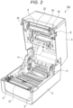
- the cover 4 is rotatable between a closed position shown in FIG. 1 and an open position shown in FIG. 2 .
- a discharge port 9 side of the printer 100 in a state shown in FIG. 1 in which the cover 4 is disposed at the closed position, a discharge port 9 side of the printer 100 is referred to as a front side, and upper, lower, left, and right directions of the printer 100 when viewed from the front side are defined.
- the case 2 has a rectangular box shape with an open upper side, and has a cutout portion 3 in a front wall portion thereof for attaching a functional unit (not shown) such as a separation unit.
- the case 2 includes a front panel 5 attached to the cutout portion 3 when not attaching the functional unit.
- FIGS. 1 and 2 show a state in which the front panel 5 is attached to the cutout portion 3.
- the printer 100 has, between the front panel 5 and the cover 4 of the case 2, the slit-shaped discharge port 9 for discharging a printed label sheet 11.
- the cover 4 has a rectangular box shape with an open lower side. Front sides of left and right side walls of the cover 4 are respectively provided with an opening lever 6 for opening the cover 4 and a fixing hook 16 that is operated by an operation of the opening lever 6.
- the fixing hook 16 engages with an engaged portion of the case 2 with the cover 4 disposed at the closed position, and locks the cover 4 at the closed position.
- An operation and display panel 7 and a power button 8 are provided on the upper wall of the cover 4.
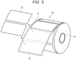
- the label sheet 11 to be attached in the case 2 is obtained by arranging and pasting a plurality of rectangular labels 13 at equal intervals to one surface of a long strip-shaped base sheet 12.
- the label 13 has an adhesive layer on a base sheet 12 side surface, is removable from the base sheet 12, and can be pasted to another article after being peeled off from the base sheet 12.
- a label sheet roll 15 is formed by rolling the label sheet 11 around a paper tube 14 with the surface of the base sheet 12 to which the labels 13 are pasted facing outward.
- the printer 100 includes a pair of left and right sheet holders 17 for attaching the label sheet roll 15.
- the label sheet roll 15 is attached between the pair of sheet holders 17 in an orientation shown in FIG. 3 . That is, the label sheet roll 15 is attached to the printer 100 with a label 13 side surface of the label sheet 11 pulled out from the label sheet roll 15 facing upward. Therefore, when the label sheet 11 pulled out from the label sheet roll 15 is conveyed toward the discharge port 9, the label sheet roll 15 rotates counterclockwise when viewing the label sheet roll 15 from a right side.
- the label sheet 11 is an example of a printing medium.
- the printer 100 includes a platen roller 21 that applies a forward conveyance force to the label sheet 11 to pull out the label sheet 11 from the label sheet roll 15.
- the platen roller 21 can also rotate in a reverse direction to back-feed the label sheet 11.
- the platen roller 21 is disposed on a front side in the case 2 adjacent to the discharge port 9.
- the platen roller 21 rotates in contact with a surface of the label sheet 11 opposite to the surface where the labels 13 are pasted to the base sheet 12.
- the printer 100 has a conveyance path 1 for conveying the label sheet 11 pulled out from the label sheet roll 15. When the cover 4 is rotated to the open position in FIG. 2 , a part of the conveyance path 1 can be opened.
- the printer 100 includes a print head 23 that prints on the labels 13 of the label sheet 11 conveyed through the conveyance path 1.
- the print head 23 is disposed on an opposite side (upper side) of the conveyance path 1 to the platen roller 21, and is pressed against the platen roller 21. Therefore, the conveyance force can be applied from the platen roller 21 to the label sheet 11 at a position where the print head 23 is pressed against the platen roller 21.
- the print head 23 is configured on a cover 4 side.
- the cover 4 includes a pressing spring (not shown) that presses the print head 23 against the platen roller 21.
- the platen roller 21 is an example of the conveyance unit that conveys the printing medium.
- the print head 23 can print by a heat transfer method, and can print by a thermal method.
- an ink ribbon 25 is interposed between the print head 23 and the label sheet 11, the ink ribbon 25 is conveyed in the same direction at the same speed as the label sheet 11, and ink of the ink ribbon 25 is melted by heat of the print head 23 to be fixed onto the labels 13.
- the printer 100 includes a supply roll 26 in which the long strip-shaped ink ribbon 25 is rolled around a paper tube, and a collection roll 27 in which the used ink ribbon 25 that passed through the print head 23 is rolled around a paper tube.
- the ink ribbon 25 stretched between the supply roll 26 and the collection roll 27 passes between the print head 23 and the platen roller 21 so as to sequentially overlap the plurality of labels 13 of the label sheet 11 conveyed through the conveyance path 1.
- the ink ribbon 25 holds ink to be transferred to the labels 13 of the label sheet 11 by heat.
- the pair of sheet holders 17 ( FIG. 2 ) in the case 2 rotatably hold both ends of the paper tube 14 of the label sheet roll 15.
- the cover 4 is provided therein with a feeding shaft 18 attached to the paper tube of the supply roll 26 of the ink ribbon 25 and a rolling shaft 19 attached to the paper tube of the collection roll 27 (not shown in FIG. 2 ).
- the feeding shaft 18 and the rolling shaft 19 are spaced apart from each other and extend in parallel.
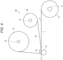
- the printer 100 When printing on the labels 13 of the label sheet 11, the printer 100 rotates the platen roller 21 counterclockwise in FIG. 4 , and conveys the label sheet 11 pulled out from the label sheet roll 15 in a forward direction (left direction in FIG. 4 ) at a constant speed. At this time, the printer 100 rotates the rolling shaft 19 attached with the collection roll 27 clockwise in FIG. 4 , and conveys the ink ribbon 25 in a forward direction at the same speed. In this state, the printer 100 prints on the labels 13 of the label sheet 11 via the print head 23.
- slack or wrinkles may occur in the ink ribbon 25. It is known that such slack or wrinkles in the ink ribbon 25 can be eliminated by back-feeding the ink ribbon 25.
- the print head 23 is moved to a retracted position spaced upward from the platen roller 21, and the feeding shaft 18 attached with the supply roll 26 is rotated counterclockwise in a reverse direction in FIG. 4 to roll back the ink ribbon 25. Accordingly, the used ink ribbon 25 is pulled out from the collection roll 27, and the collection roll 27 rotates counterclockwise in FIG. 4 .
- the printer 100 includes a turning force generation mechanism 30 that generates a turning force in a direction in which the ink ribbon 25 is rolled around the rolling shaft 19 of the collection roll 27 during back-feeding in order to prevent occurrence of such slack during back-feeding of the ink ribbon 25.
- a turning force generation mechanism 30 that generates a turning force in a direction in which the ink ribbon 25 is rolled around the rolling shaft 19 of the collection roll 27 during back-feeding in order to prevent occurrence of such slack during back-feeding of the ink ribbon 25.
- FIG. 5 is a cross-sectional perspective view showing the turning force generation mechanism 30 and the peripheral structure thereof
- FIG. 6 is a plan view of a drive mechanism 40 that drives the rolling shaft 19 of the collection roll 27 as viewed from a left side of the printer 100 (a direction of an arrow F6 in FIG. 5 )
- FIG. 7 is a side view of the structure in FIG. 5 as viewed from a direction of an arrow F7
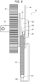
- FIG. 8 is a rear view of the turning force generation mechanism 30 as viewed from a direction of an arrow F8 in FIG. 7 (a rear side of the printer 100).
- rotation directions of the feeding shaft 18 and the rolling shaft 19 and a traveling direction of the ink ribbon 25 when conveying the ink ribbon 25 in the forward direction are indicated by an arrow A
- rotation directions of the feeding shaft 18 and the rolling shaft 19 and a traveling direction of the ink ribbon 25 when back-feeding the ink ribbon 25 are indicated by an arrow B.
- the printer 100 includes a wheel 10 for coaxially connecting one end (left end) of the rolling shaft 19.
- the wheel 10 is rotatably accommodated in a recess 281 of a frame 28 fixed to the left side of the cover 4.
- the wheel 10 receives and meshes with a bevel-shaped gear (not shown) provided at the left end of the rolling shaft 19 of the collection roll 27. Therefore, the rolling shaft 19 rotates in a direction in which the wheel 10 rotates.
- the wheel 10 coaxially and integrally includes a rotation shaft 20 extending through a bottom of the recess 281. That is, the rotation shaft 20 is a shaft that is coaxially and integrally connected to the rolling shaft 19.
- the rotation shaft 20 extends leftward through the bottom of the recess 281 of the frame 28.
- a left end of the rotation shaft 20 is rotatably supported by a turning member 32 and a one-way bearing 31 to be described later, which are rotatably attached to a metal plate 29 fixed to the cover 4 at a position spaced apart on a left side of the frame 28.
- the metal plate 29 includes an aperture 291 having a protruding height of two to three times a plate thickness.
- the aperture 291 functions as a bearing that rotatably supports a left end of the turning member 32. Therefore, a bearing that rotatably supports the left end of the rotation shaft 20 can be omitted, and an axial thickness of the turning force generation mechanism 30 can be reduced.
- the rotation shaft 20 has two one-way bearings 22 and 31 coaxially mounted thereon.
- One one-way bearing 22 close to the wheel 10 is attached between a gear 24 and the rotation shaft 20.
- the other one-way bearing 31 on a metal plate 29 side is a component of the turning force generation mechanism 30, and is attached between the turning member 32 of the turning force generation mechanism 30 and the rotation shaft 20.
- the one-way bearing 31 of the turning force generation mechanism 30 is disposed adjacent to the one-way bearing 22 on a side opposite to the wheel 10.
- the one-way bearing 31 of the turning force generation mechanism 30 includes an inner sheath fixed to the rotation shaft 20 and an outer sheath attached to the outside of the inner sheath via a sprag.
- the one-way bearing 31 transmits the turning force to the turning member 32 when the rotation shaft 20 is rotated in the reverse direction by back-feeding the ink ribbon 25, and allows the rotation shaft 20 to idle with respect to the turning member 32 when conveying the ink ribbon 25 in the forward direction.
- the drive mechanism 40 that rotates the gear 24 includes the motor 41, first to fourth gears 43 to 46 that sequentially mesh with a gear 42 fixed to a rotation shaft of the motor 41, and a fifth gear 47 with a torque limiter provided between the fourth gear 46 and the gear 24.
- the turning force generation mechanism 30 includes a tension spring 33 whose lower end is fixed to the metal plate 29 and whose upper end is fixed to the turning member 32.
- the tension spring 33 is an example of an elastic member that is elastically deformed during back-feeding.
- the metal plate 29 includes a hook 292 for hooking a lower end 331 of the tension spring 33.
- the turning member 32 is provided with a hook 321 for hooking an upper end 332 of the tension spring 33, which protrudes from an outer peripheral surface thereof.
- FIGS. 7 and 8 show an initial state in which the tension spring 33 is not elastically deformed.
- the turning member 32 has an annular holding groove 322 around which the stretched tension spring 33 is rolled.
- the hook 321 protrudes from a bottom of the holding groove 322.
- the metal plate 29 is disposed on a left side of the holding groove 322.
- the metal plate 29 functions as a retaining plate for preventing the tension spring 33 rolled around the holding groove 322 from coming off from the holding groove 322 due to a restoring force thereof.
- the turning force generation mechanism 30 when rotation of the feeding shaft 18 in the reverse direction is stopped to stop rotation of the supply roll 26 at the end of the back-feeding of the ink ribbon 25, the collection roll 27 does not continue to rotate in the reverse direction due to the inertial force, and slack in the ink ribbon 25 as indicated by a broken line 251 in FIG. 6 does not occur. Therefore, according to at least one embodiment, wrinkles in the ink ribbon 25 are eliminated by back-feeding the ink ribbon 25, and no new slack occurs in the ink ribbon 25 after the back-feeding, whereby print quality can be improved.
Landscapes
- Impression-Transfer Materials And Handling Thereof (AREA)
- Electronic Switches (AREA)
Abstract
A printer includes a feeding shaft, a rolling shaft, a conveyance unit, a print head, and a turning force generation mechanism. The feeding shaft rotatably holds a supply roll in which the ink ribbon is rolled. The rolling shaft rotatably holds a collection roll in which the ink ribbon fed from the supply roll is rolled. The conveyance unit conveys a printing medium along the ink ribbon that moves from the supply roll toward the collection roll. The print head prints by bringing the ink ribbon into contact with the printing medium conveyed by the conveyance unit. The turning force generation mechanism generates a turning force in a direction in which the ink ribbon is rolled around the rolling shaft during back-feeding of moving the ink ribbon in a reverse direction by rotating the feeding shaft in a direction reverse to a feeding direction of the ink ribbon.
Description
- Embodiments described herein relate generally to a printer that prints on a printing medium using an ink ribbon.
- A printer that prints on a printing medium using an ink ribbon includes a feeding shaft attached with a supply roll in which the ink ribbon is rolled, a print head, and a rolling shaft attached with a collection roll in which the used ink ribbon is rolled. When printing on the printing medium with the printer, the printing medium is conveyed, the ink ribbon is fed from the supply roll, the printing medium and the ink ribbon overlap and pass through the print head, and the used ink ribbon after printing is collected by the collection roll.
- The ink ribbon may have slack or wrinkles due to the printing operation. When the slack or wrinkles occur in the ink ribbon, a printing failure may occur. Therefore, the printer using the ink ribbon generally includes a mechanism for eliminating the slack or wrinkles in the ink ribbon.
- It is known that slack or wrinkles in an ink ribbon can be eliminated by, for example, back-feeding the ink ribbon in a reverse direction. When back-feeding the ink ribbon, a feeding shaft is rotated in a reverse direction to pull out the used ink ribbon from a collection roll.
- However, when back-feeding the ink ribbon, the collection roll continues to rotate due to an inertial force after reverse rotation of the feeding shaft is stopped, which may cause new slack in the ink ribbon between the collection roll and a print head.
- To this end, a printer and a method according to appended claims are provided.
-
-
FIG. 1 is an external perspective view showing a printer according to at least one embodiment; -
FIG. 2 is a perspective view showing a state in which a cover is opened; -
FIG. 3 is a perspective view showing a label sheet roll; -
FIG. 4 is a schematic view showing an internal structure; -
FIG. 5 is a cross-sectional perspective view showing a turning force generation mechanism connected to one end of a rolling shaft and a peripheral structure thereof; -
FIG. 6 is a plan view of a drive mechanism as viewed from a direction of an arrow F6; -
FIG. 7 is a side view of a structure inFIG. 5 as viewed from a direction of an arrow F7; and -
FIG. 8 is a rear view of a structure inFIG. 7 as viewed from a direction of an arrow F8. - In general, according to at least one embodiment, a printer capable of preventing occurrence of slack during back-feeding of an ink ribbon is provided.
- A printer according to at least one embodiment includes a feeding shaft, a rolling shaft, a conveyance unit (conveyor), a print head, and a turning force generation mechanism. The feeding shaft rotatably holds a supply roll in which the ink ribbon is rolled. The rolling shaft rotatably holds a collection roll in which the ink ribbon fed from the supply roll is rolled. The conveyance unit conveys a printing medium along the ink ribbon that moves from the supply roll toward the collection roll. The print head prints by bringing the ink ribbon into contact with the printing medium conveyed by the conveyance unit. The turning force generation mechanism generates a turning force in a direction in which the ink ribbon is rolled around the rolling shaft during back-feeding of moving the ink ribbon in a reverse direction by rotating the feeding shaft in a direction reverse to a feeding direction of the ink ribbon.
- Hereinafter, at least one embodiment will be described with reference to the drawings.
- As shown in
FIGS. 1 and2 , a label printer 100 (hereinafter, simply referred to as a printer 100) includes acase 2 and acover 4. Thecase 2 constitutes a lower casing of theprinter 100, and thecover 4 constitutes an upper casing of the printer. Thecover 4 is connected to thecase 2 via a hinge (not shown) provided on a rear end side. Thecover 4 is rotatable between a closed position shown inFIG. 1 and an open position shown inFIG. 2 . In the following description, in a state shown inFIG. 1 in which thecover 4 is disposed at the closed position, adischarge port 9 side of theprinter 100 is referred to as a front side, and upper, lower, left, and right directions of theprinter 100 when viewed from the front side are defined. - The
case 2 has a rectangular box shape with an open upper side, and has acutout portion 3 in a front wall portion thereof for attaching a functional unit (not shown) such as a separation unit. Thecase 2 includes afront panel 5 attached to thecutout portion 3 when not attaching the functional unit.FIGS. 1 and2 show a state in which thefront panel 5 is attached to thecutout portion 3. Theprinter 100 has, between thefront panel 5 and thecover 4 of thecase 2, the slit-shaped discharge port 9 for discharging a printedlabel sheet 11. - The
cover 4 has a rectangular box shape with an open lower side. Front sides of left and right side walls of thecover 4 are respectively provided with anopening lever 6 for opening thecover 4 and afixing hook 16 that is operated by an operation of theopening lever 6. Thefixing hook 16 engages with an engaged portion of thecase 2 with thecover 4 disposed at the closed position, and locks thecover 4 at the closed position. An operation anddisplay panel 7 and apower button 8 are provided on the upper wall of thecover 4. - As shown in
FIG. 3 , thelabel sheet 11 to be attached in thecase 2 is obtained by arranging and pasting a plurality ofrectangular labels 13 at equal intervals to one surface of a long strip-shaped base sheet 12. Thelabel 13 has an adhesive layer on abase sheet 12 side surface, is removable from thebase sheet 12, and can be pasted to another article after being peeled off from thebase sheet 12. Alabel sheet roll 15 is formed by rolling thelabel sheet 11 around apaper tube 14 with the surface of thebase sheet 12 to which thelabels 13 are pasted facing outward. - As shown in
FIG. 2 , theprinter 100 includes a pair of left andright sheet holders 17 for attaching thelabel sheet roll 15. Thelabel sheet roll 15 is attached between the pair ofsheet holders 17 in an orientation shown inFIG. 3 . That is, thelabel sheet roll 15 is attached to theprinter 100 with alabel 13 side surface of thelabel sheet 11 pulled out from thelabel sheet roll 15 facing upward. Therefore, when thelabel sheet 11 pulled out from thelabel sheet roll 15 is conveyed toward thedischarge port 9, thelabel sheet roll 15 rotates counterclockwise when viewing thelabel sheet roll 15 from a right side. Thelabel sheet 11 is an example of a printing medium. - As shown in
FIGS. 2 and4 , theprinter 100 includes aplaten roller 21 that applies a forward conveyance force to thelabel sheet 11 to pull out thelabel sheet 11 from thelabel sheet roll 15. Theplaten roller 21 can also rotate in a reverse direction to back-feed thelabel sheet 11. Theplaten roller 21 is disposed on a front side in thecase 2 adjacent to thedischarge port 9. Theplaten roller 21 rotates in contact with a surface of thelabel sheet 11 opposite to the surface where thelabels 13 are pasted to thebase sheet 12. Theprinter 100 has aconveyance path 1 for conveying thelabel sheet 11 pulled out from thelabel sheet roll 15. When thecover 4 is rotated to the open position inFIG. 2 , a part of theconveyance path 1 can be opened. - The
printer 100 includes aprint head 23 that prints on thelabels 13 of thelabel sheet 11 conveyed through theconveyance path 1. Theprint head 23 is disposed on an opposite side (upper side) of theconveyance path 1 to theplaten roller 21, and is pressed against theplaten roller 21. Therefore, the conveyance force can be applied from theplaten roller 21 to thelabel sheet 11 at a position where theprint head 23 is pressed against theplaten roller 21. Theprint head 23 is configured on acover 4 side. Thecover 4 includes a pressing spring (not shown) that presses theprint head 23 against theplaten roller 21. Theplaten roller 21 is an example of the conveyance unit that conveys the printing medium. - The
print head 23 can print by a heat transfer method, and can print by a thermal method. When printing by the heat transfer method, anink ribbon 25 is interposed between theprint head 23 and thelabel sheet 11, theink ribbon 25 is conveyed in the same direction at the same speed as thelabel sheet 11, and ink of theink ribbon 25 is melted by heat of theprint head 23 to be fixed onto thelabels 13. - As shown in
FIG. 4 , theprinter 100 includes asupply roll 26 in which the long strip-shapedink ribbon 25 is rolled around a paper tube, and acollection roll 27 in which the usedink ribbon 25 that passed through theprint head 23 is rolled around a paper tube. Theink ribbon 25 stretched between thesupply roll 26 and thecollection roll 27 passes between theprint head 23 and theplaten roller 21 so as to sequentially overlap the plurality oflabels 13 of thelabel sheet 11 conveyed through theconveyance path 1. Theink ribbon 25 holds ink to be transferred to thelabels 13 of thelabel sheet 11 by heat. - The pair of sheet holders 17 (
FIG. 2 ) in thecase 2 rotatably hold both ends of thepaper tube 14 of thelabel sheet roll 15. Thecover 4 is provided therein with a feedingshaft 18 attached to the paper tube of thesupply roll 26 of theink ribbon 25 and a rollingshaft 19 attached to the paper tube of the collection roll 27 (not shown inFIG. 2 ). The feedingshaft 18 and the rollingshaft 19 are spaced apart from each other and extend in parallel. - When printing on the
labels 13 of thelabel sheet 11, theprinter 100 rotates theplaten roller 21 counterclockwise inFIG. 4 , and conveys thelabel sheet 11 pulled out from thelabel sheet roll 15 in a forward direction (left direction inFIG. 4 ) at a constant speed. At this time, theprinter 100 rotates the rollingshaft 19 attached with thecollection roll 27 clockwise inFIG. 4 , and conveys theink ribbon 25 in a forward direction at the same speed. In this state, theprinter 100 prints on thelabels 13 of thelabel sheet 11 via theprint head 23. - When the printing operation is continued, slack or wrinkles may occur in the
ink ribbon 25. It is known that such slack or wrinkles in theink ribbon 25 can be eliminated by back-feeding theink ribbon 25. When back-feeding theink ribbon 25, theprint head 23 is moved to a retracted position spaced upward from theplaten roller 21, and the feedingshaft 18 attached with thesupply roll 26 is rotated counterclockwise in a reverse direction inFIG. 4 to roll back theink ribbon 25. Accordingly, the usedink ribbon 25 is pulled out from thecollection roll 27, and thecollection roll 27 rotates counterclockwise inFIG. 4 . - When back-feeding of the
ink ribbon 25 is ended, rotation of the feedingshaft 18 is stopped. At this time, since thecollection roll 27 rotates counterclockwise inFIG. 4 , thecollection roll 27 continues to rotate counterclockwise due to an inertial force. In this case, new slack may occur in theink ribbon 25 between thesupply roll 26 that stops rotating and thecollection roll 27 that continues to rotate. In this case, an amount of slack increases as a diameter (weight) of thecollection roll 27 increases. - The
printer 100 according to the at least one embodiment includes a turningforce generation mechanism 30 that generates a turning force in a direction in which theink ribbon 25 is rolled around the rollingshaft 19 of thecollection roll 27 during back-feeding in order to prevent occurrence of such slack during back-feeding of theink ribbon 25. Hereinafter, the turningforce generation mechanism 30 and a peripheral structure thereof will be described with reference toFIGS. 5 to 8 . -
FIG. 5 is a cross-sectional perspective view showing the turningforce generation mechanism 30 and the peripheral structure thereof,FIG. 6 is a plan view of adrive mechanism 40 that drives the rollingshaft 19 of thecollection roll 27 as viewed from a left side of the printer 100 (a direction of an arrow F6 inFIG. 5 ),FIG. 7 is a side view of the structure inFIG. 5 as viewed from a direction of an arrow F7, andFIG. 8 is a rear view of the turningforce generation mechanism 30 as viewed from a direction of an arrow F8 inFIG. 7 (a rear side of the printer 100). - In order to make the description easy to understand, in each drawing, rotation directions of the feeding
shaft 18 and the rollingshaft 19 and a traveling direction of theink ribbon 25 when conveying theink ribbon 25 in the forward direction are indicated by an arrow A, and rotation directions of the feedingshaft 18 and the rollingshaft 19 and a traveling direction of theink ribbon 25 when back-feeding theink ribbon 25 are indicated by an arrow B. - As shown in
FIG. 5 , theprinter 100 includes awheel 10 for coaxially connecting one end (left end) of the rollingshaft 19. Thewheel 10 is rotatably accommodated in arecess 281 of aframe 28 fixed to the left side of thecover 4. When thecollection roll 27 is attached to theprinter 100, thewheel 10 receives and meshes with a bevel-shaped gear (not shown) provided at the left end of the rollingshaft 19 of thecollection roll 27. Therefore, the rollingshaft 19 rotates in a direction in which thewheel 10 rotates. Thewheel 10 coaxially and integrally includes arotation shaft 20 extending through a bottom of therecess 281. That is, therotation shaft 20 is a shaft that is coaxially and integrally connected to the rollingshaft 19. - The
rotation shaft 20 extends leftward through the bottom of therecess 281 of theframe 28. A left end of therotation shaft 20 is rotatably supported by a turningmember 32 and a one-way bearing 31 to be described later, which are rotatably attached to ametal plate 29 fixed to thecover 4 at a position spaced apart on a left side of theframe 28. Themetal plate 29 includes anaperture 291 having a protruding height of two to three times a plate thickness. Theaperture 291 functions as a bearing that rotatably supports a left end of the turningmember 32. Therefore, a bearing that rotatably supports the left end of therotation shaft 20 can be omitted, and an axial thickness of the turningforce generation mechanism 30 can be reduced. - The
rotation shaft 20 has two one-way bearings way bearing 22 close to thewheel 10 is attached between agear 24 and therotation shaft 20. The other one-way bearing 31 on ametal plate 29 side is a component of the turningforce generation mechanism 30, and is attached between the turningmember 32 of the turningforce generation mechanism 30 and therotation shaft 20. The one-way bearing 31 of the turningforce generation mechanism 30 is disposed adjacent to the one-way bearing 22 on a side opposite to thewheel 10. - The one-
way bearing 22 includes an inner sheath fixed to therotation shaft 20 and an outer sheath attached to the outside of the inner sheath via a sprag. The one-way bearing 22 transmits a rotational force to therotation shaft 20 when thegear 24 is rotated in a forward direction by thedrive mechanism 40 shown inFIG. 6 , and allows therotation shaft 20 to rotate in a reverse direction with thegear 24 stopped. That is, the one-way bearing 22 functions to transmit the rotational force transmitted from a motor 41 (FIG. 6 ) to therotation shaft 20 via thegear 24 when conveying theink ribbon 25 in the forward direction, and rotate thecollection roll 27 in a direction in which theink ribbon 25 is rolled. The one-way bearing 22 functions to allow the collection roll 27 (rotation shaft 20) to rotate in the reverse direction (idle) when back-feeding theink ribbon 25 with the motor 41 (gear 24) stopped. - The one-
way bearing 31 of the turningforce generation mechanism 30 includes an inner sheath fixed to therotation shaft 20 and an outer sheath attached to the outside of the inner sheath via a sprag. The one-way bearing 31 transmits the turning force to the turningmember 32 when therotation shaft 20 is rotated in the reverse direction by back-feeding theink ribbon 25, and allows therotation shaft 20 to idle with respect to the turningmember 32 when conveying theink ribbon 25 in the forward direction. - As shown in
FIG. 6 , thedrive mechanism 40 that rotates thegear 24 includes themotor 41, first tofourth gears 43 to 46 that sequentially mesh with agear 42 fixed to a rotation shaft of themotor 41, and a fifth gear 47 with a torque limiter provided between thefourth gear 46 and thegear 24. - As shown in
FIGS. 7 and8 , the turningforce generation mechanism 30 includes atension spring 33 whose lower end is fixed to themetal plate 29 and whose upper end is fixed to the turningmember 32. Thetension spring 33 is an example of an elastic member that is elastically deformed during back-feeding. Themetal plate 29 includes ahook 292 for hooking alower end 331 of thetension spring 33. The turningmember 32 is provided with ahook 321 for hooking anupper end 332 of thetension spring 33, which protrudes from an outer peripheral surface thereof.FIGS. 7 and8 show an initial state in which thetension spring 33 is not elastically deformed. - The turning
member 32 has anannular holding groove 322 around which the stretchedtension spring 33 is rolled. Thehook 321 protrudes from a bottom of the holdinggroove 322. Themetal plate 29 is disposed on a left side of the holdinggroove 322. Themetal plate 29 functions as a retaining plate for preventing thetension spring 33 rolled around the holdinggroove 322 from coming off from the holdinggroove 322 due to a restoring force thereof. - When the
rotation shaft 20 rotates clockwise inFIG. 7 during back-feeding, the turningmember 32 turns clockwise inFIG. 7 , and thetension spring 33 is stretched and rolled around the holdinggroove 322. When thetension spring 33 is stretched, the restoring force thereof acts in a direction in which the turningmember 32 turns counterclockwise inFIG. 7 . That is, during back-feeding of theink ribbon 25, tension is always applied to theink ribbon 25 between theprint head 23 and thecollection roll 27. In other words, when back-feeding theink ribbon 25, a counterclockwise rotational force inFIG. 7 is applied to therotation shaft 20, and a rotational force in a direction in which theink ribbon 25 is rolled is applied to the rollingshaft 19. - That is, if the turning
force generation mechanism 30 according to at least one embodiment is used, when rotation of the feedingshaft 18 in the reverse direction is stopped to stop rotation of thesupply roll 26 at the end of the back-feeding of theink ribbon 25, thecollection roll 27 does not continue to rotate in the reverse direction due to the inertial force, and slack in theink ribbon 25 as indicated by abroken line 251 inFIG. 6 does not occur. Therefore, according to at least one embodiment, wrinkles in theink ribbon 25 are eliminated by back-feeding theink ribbon 25, and no new slack occurs in theink ribbon 25 after the back-feeding, whereby print quality can be improved. - While embodiments have been described, the embodiments have been presented by way of example and are not intended to limit the scope of the disclosure. The embodiments can be implemented in various other forms, and various omissions, substitutions, and changes can be made in a scope not departing from the gist of the exemplary embodiments. The embodiments and modifications thereof are included in the scope and the gist of the disclosure, and are included in a scope of the disclosure disclosed in the claims and equivalents thereof.
Claims (14)
- A printer (100) comprising:a feeding shaft (18) configured to rotatably hold a supply roll (26) in which an ink ribbon is rolled;a rolling shaft (19) configured to rotatably hold a collection roll (27) in which the ink ribbon fed from the supply roll is rolled;a conveyor (21) configured to convey a printing medium along the ink ribbon that moves from the supply roll toward the collection roll;a print head (23) configured to print by bringing the ink ribbon into contact with the printing medium conveyed by the conveyor; anda turning force generation mechanism (30) configured to generate a turning force in a direction in which the ink ribbon is rolled around the rolling shaft during back-feeding of moving the ink ribbon in a reverse direction by rotating the feeding shaft in a direction reverse to a feeding direction of the ink ribbon.
- The printer according to claim 1, wherein
the turning force generation mechanism includes:
a one-way bearing including a turning member (32) that idles when the rolling shaft rotates in the rolling direction and turns integrally with the rolling shaft during the back-feeding in which the rolling shaft rotates in a direction reverse to the rolling direction. - The printer according to claim 2, wherein
the turning force generation mechanism includes:
an elastic member (33) elastically deformed by turning of the turning member in the reverse direction and the elastic member turns the turning member in the rolling direction due to a restoring force of the elastic member. - The printer according to claim 3, wherein
the elastic member includes a tension spring whose one end is fixed to the turning member, and the tension spring is stretched and rolled around the turning member as the turning member turns in the reverse direction. - The printer according to claim 4, further comprising:
a retaining plate (29) fixed to the turning member and the retaining plate forming a holding groove around which the tension spring is rolled while being restrained from moving together with the turning member. - The printer according to claim 5, wherein
the other end of the tension spring is fixed to the retaining plate. - The printer according to claim 6, wherein the retaining plate (29) includes a hook (292) for hooking the other end of the tension spring (33).
- The printer according to any one of claims 1 to 7, wherein the printer is a label printer.
- The printer according to any one of claims 1 to 8, further comprising a driver configured to drive the rolling shaft.
- The printer according to claim 9, wherein the driver includes a motor.
- The printer according to any one of claims 1 to 10, wherein the conveyor includes a platen roller.
- The printer according to any one of claims 1 to 11, wherein the printing medium includes a label sheet.
- The printer according to any one of claims 4 to 12, wherein retaining plate includes a metal plate.
- A method of operating a label printer comprising:rotatably holding via a feeding shaft a supply roll in which an ink ribbon is rolled;rotatably holding via a rolling shaft a collection roll in which the ink ribbon fed from the supply roll is rolled;conveying via a conveyor a printing medium along the ink ribbon that moves from the supply roll toward the collection roll;printing via a print head by bringing the ink ribbon into contact with the printing medium conveyed by the conveyor; andgenerating a turning force via a turning force generation mechanism in a direction in which the ink ribbon is rolled around the rolling shaft during back-feeding of moving the ink ribbon in a reverse direction by rotating the feeding shaft in a direction reverse to a feeding direction of the ink ribbon.
Applications Claiming Priority (1)
| Application Number | Priority Date | Filing Date | Title |
|---|---|---|---|
| JP2023159053A JP7844414B2 (en) | 2023-09-22 | 2023-09-22 | printer |
Publications (1)
| Publication Number | Publication Date |
|---|---|
| EP4527628A1 true EP4527628A1 (en) | 2025-03-26 |
Family
ID=91184711
Family Applications (1)
| Application Number | Title | Priority Date | Filing Date |
|---|---|---|---|
| EP24176478.6A Pending EP4527628A1 (en) | 2023-09-22 | 2024-05-16 | Printer that prints on a printing medium using an ink ribbon |
Country Status (4)
| Country | Link |
|---|---|
| US (1) | US12679127B2 (en) |
| EP (1) | EP4527628A1 (en) |
| JP (1) | JP7844414B2 (en) |
| CN (1) | CN119682399A (en) |
Citations (3)
| Publication number | Priority date | Publication date | Assignee | Title |
|---|---|---|---|---|
| JP2004174727A (en) * | 2002-11-25 | 2004-06-24 | Sato Corp | Printer |
| US20180370265A1 (en) * | 2017-06-22 | 2018-12-27 | Toshiba Tec Kabushiki Kaisha | Printer and method for automatically eliminating slackness of printing medium |
| CN115848027A (en) * | 2021-09-24 | 2023-03-28 | 卡西欧计算机株式会社 | Printing device |
Family Cites Families (7)
| Publication number | Priority date | Publication date | Assignee | Title |
|---|---|---|---|---|
| JPS6359568A (en) * | 1986-08-29 | 1988-03-15 | Ricoh Co Ltd | Thermal transfer recording device |
| JPH02301468A (en) * | 1989-05-17 | 1990-12-13 | Toshiba Corp | Image forming apparatus |
| JPH05193221A (en) * | 1991-07-29 | 1993-08-03 | Kanzaki Paper Mfg Co Ltd | Thermal transfer printer |
| JPH06336076A (en) * | 1993-05-27 | 1994-12-06 | Tokyo Electric Co Ltd | Transfer printer |
| JP4208986B2 (en) * | 1997-11-14 | 2009-01-14 | 株式会社サトー | Ribbon tension device for printer |
| JP2001030594A (en) | 1999-07-26 | 2001-02-06 | Tamura Electric Works Ltd | Ink ribbon cassette support structure |
| JP5978117B2 (en) * | 2012-11-30 | 2016-08-24 | 日本電産サンキョー株式会社 | Printing device |
-
2023
- 2023-09-22 JP JP2023159053A patent/JP7844414B2/en active Active
-
2024
- 2024-04-17 CN CN202410462171.XA patent/CN119682399A/en active Pending
- 2024-04-22 US US18/642,176 patent/US12679127B2/en active Active
- 2024-05-16 EP EP24176478.6A patent/EP4527628A1/en active Pending
Patent Citations (3)
| Publication number | Priority date | Publication date | Assignee | Title |
|---|---|---|---|---|
| JP2004174727A (en) * | 2002-11-25 | 2004-06-24 | Sato Corp | Printer |
| US20180370265A1 (en) * | 2017-06-22 | 2018-12-27 | Toshiba Tec Kabushiki Kaisha | Printer and method for automatically eliminating slackness of printing medium |
| CN115848027A (en) * | 2021-09-24 | 2023-03-28 | 卡西欧计算机株式会社 | Printing device |
Also Published As
| Publication number | Publication date |
|---|---|
| US20250100313A1 (en) | 2025-03-27 |
| CN119682399A (en) | 2025-03-25 |
| US12679127B2 (en) | 2026-07-14 |
| JP7844414B2 (en) | 2026-04-13 |
| JP2025050329A (en) | 2025-04-04 |
Similar Documents
| Publication | Publication Date | Title |
|---|---|---|
| CN109941005B (en) | Tape printing apparatus | |
| JP7322638B2 (en) | Printer and cassette for printing | |
| JPH05301405A (en) | Mechanism for preventing carbon ribbon from relaxing in printing apparatus | |
| JP2000218892A (en) | Thermal transfer recording device | |
| JP7761116B2 (en) | Printing cassette | |
| JPH0973138A (en) | Paper magazine | |
| JP2023121804A (en) | cassette | |
| US20250100313A1 (en) | Printer | |
| CN108724992B (en) | Ink ribbon winding mechanism and tape printing apparatus | |
| US20220212484A1 (en) | Printing cassette | |
| JP7069706B2 (en) | Ribbon winding mechanism and tape printing device | |
| JP5978117B2 (en) | Printing device | |
| US6874963B2 (en) | Driving apparatus having a feeding part power-engaging removal device in image forming apparatus | |
| JP7259442B2 (en) | Ribbon feeding mechanism and tape printer | |
| JP4538059B2 (en) | Ribbon feeder | |
| JP7821766B2 (en) | printer | |
| JPH0839908A (en) | Printing cassette | |
| JP2012200970A (en) | Tape cassette, tape cassette and tape printer | |
| JP2004209807A (en) | Image forming apparatus | |
| JP2000006488A (en) | Cassette for thermal transfer printer | |
| JP2514549Y2 (en) | Ink film pressure release device in recording apparatus | |
| JP2015189578A (en) | Sheet conveying device and printer | |
| JP2007030959A (en) | Labeling device | |
| JP2629820B2 (en) | Thermal printer | |
| JP2000001013A (en) | Thermal transfer printer |
Legal Events
| Date | Code | Title | Description |
|---|---|---|---|
| PUAI | Public reference made under article 153(3) epc to a published international application that has entered the european phase |
Free format text: ORIGINAL CODE: 0009012 |
|
| STAA | Information on the status of an ep patent application or granted ep patent |
Free format text: STATUS: THE APPLICATION HAS BEEN PUBLISHED |
|
| AK | Designated contracting states |
Kind code of ref document: A1 Designated state(s): AL AT BE BG CH CY CZ DE DK EE ES FI FR GB GR HR HU IE IS IT LI LT LU LV MC ME MK MT NL NO PL PT RO RS SE SI SK SM TR |
|
| STAA | Information on the status of an ep patent application or granted ep patent |
Free format text: STATUS: REQUEST FOR EXAMINATION WAS MADE |
|
| 17P | Request for examination filed |
Effective date: 20250926 |