EP4527620A1 - System for bonding films and method for preparing composite film using the same - Google Patents
System for bonding films and method for preparing composite film using the same Download PDFInfo
- Publication number
- EP4527620A1 EP4527620A1 EP24198669.4A EP24198669A EP4527620A1 EP 4527620 A1 EP4527620 A1 EP 4527620A1 EP 24198669 A EP24198669 A EP 24198669A EP 4527620 A1 EP4527620 A1 EP 4527620A1
- Authority
- EP
- European Patent Office
- Prior art keywords
- film
- roller
- deformable
- bonding
- outer layer
- Prior art date
- Legal status (The legal status is an assumption and is not a legal conclusion. Google has not performed a legal analysis and makes no representation as to the accuracy of the status listed.)
- Granted
Links
Images




Classifications
-
- B—PERFORMING OPERATIONS; TRANSPORTING
- B32—LAYERED PRODUCTS
- B32B—LAYERED PRODUCTS, i.e. PRODUCTS BUILT-UP OF STRATA OF FLAT OR NON-FLAT, e.g. CELLULAR OR HONEYCOMB, FORM
- B32B37/00—Methods or apparatus for laminating, e.g. by curing or by ultrasonic bonding
- B32B37/0046—Methods or apparatus for laminating, e.g. by curing or by ultrasonic bonding characterised by constructional aspects of the apparatus
- B32B37/0053—Constructional details of laminating machines comprising rollers; Constructional features of the rollers
-
- B—PERFORMING OPERATIONS; TRANSPORTING
- B29—WORKING OF PLASTICS; WORKING OF SUBSTANCES IN A PLASTIC STATE IN GENERAL
- B29C—SHAPING OR JOINING OF PLASTICS; SHAPING OF MATERIAL IN A PLASTIC STATE, NOT OTHERWISE PROVIDED FOR; AFTER-TREATMENT OF THE SHAPED PRODUCTS, e.g. REPAIRING
- B29C66/00—General aspects of processes or apparatus for joining preformed parts
- B29C66/80—General aspects of machine operations or constructions and parts thereof
- B29C66/83—General aspects of machine operations or constructions and parts thereof characterised by the movement of the joining or pressing tools
- B29C66/834—General aspects of machine operations or constructions and parts thereof characterised by the movement of the joining or pressing tools moving with the parts to be joined
- B29C66/8341—Roller, cylinder or drum types; Band or belt types; Ball types
- B29C66/83411—Roller, cylinder or drum types
- B29C66/83413—Roller, cylinder or drum types cooperating rollers, cylinders or drums
-
- B—PERFORMING OPERATIONS; TRANSPORTING
- B29—WORKING OF PLASTICS; WORKING OF SUBSTANCES IN A PLASTIC STATE IN GENERAL
- B29C—SHAPING OR JOINING OF PLASTICS; SHAPING OF MATERIAL IN A PLASTIC STATE, NOT OTHERWISE PROVIDED FOR; AFTER-TREATMENT OF THE SHAPED PRODUCTS, e.g. REPAIRING
- B29C66/00—General aspects of processes or apparatus for joining preformed parts
- B29C66/40—General aspects of joining substantially flat articles, e.g. plates, sheets or web-like materials; Making flat seams in tubular or hollow articles; Joining single elements to substantially flat surfaces
- B29C66/41—Joining substantially flat articles ; Making flat seams in tubular or hollow articles
- B29C66/45—Joining of substantially the whole surface of the articles
-
- B—PERFORMING OPERATIONS; TRANSPORTING
- B32—LAYERED PRODUCTS
- B32B—LAYERED PRODUCTS, i.e. PRODUCTS BUILT-UP OF STRATA OF FLAT OR NON-FLAT, e.g. CELLULAR OR HONEYCOMB, FORM
- B32B37/00—Methods or apparatus for laminating, e.g. by curing or by ultrasonic bonding
- B32B37/0007—Methods or apparatus for laminating, e.g. by curing or by ultrasonic bonding involving treatment or provisions in order to avoid deformation or air inclusion, e.g. to improve surface quality
- B32B37/0015—Methods or apparatus for laminating, e.g. by curing or by ultrasonic bonding involving treatment or provisions in order to avoid deformation or air inclusion, e.g. to improve surface quality to avoid warp or curl
-
- B—PERFORMING OPERATIONS; TRANSPORTING
- B32—LAYERED PRODUCTS
- B32B—LAYERED PRODUCTS, i.e. PRODUCTS BUILT-UP OF STRATA OF FLAT OR NON-FLAT, e.g. CELLULAR OR HONEYCOMB, FORM
- B32B37/00—Methods or apparatus for laminating, e.g. by curing or by ultrasonic bonding
- B32B37/0076—Methods or apparatus for laminating, e.g. by curing or by ultrasonic bonding characterised in that the layers are not bonded on the totality of their surfaces
-
- B—PERFORMING OPERATIONS; TRANSPORTING
- B32—LAYERED PRODUCTS
- B32B—LAYERED PRODUCTS, i.e. PRODUCTS BUILT-UP OF STRATA OF FLAT OR NON-FLAT, e.g. CELLULAR OR HONEYCOMB, FORM
- B32B37/00—Methods or apparatus for laminating, e.g. by curing or by ultrasonic bonding
- B32B37/10—Methods or apparatus for laminating, e.g. by curing or by ultrasonic bonding characterised by the pressing technique, e.g. using action of vacuum or fluid pressure
-
- B—PERFORMING OPERATIONS; TRANSPORTING
- B32—LAYERED PRODUCTS
- B32B—LAYERED PRODUCTS, i.e. PRODUCTS BUILT-UP OF STRATA OF FLAT OR NON-FLAT, e.g. CELLULAR OR HONEYCOMB, FORM
- B32B37/00—Methods or apparatus for laminating, e.g. by curing or by ultrasonic bonding
- B32B37/12—Methods or apparatus for laminating, e.g. by curing or by ultrasonic bonding characterised by using adhesives
-
- B—PERFORMING OPERATIONS; TRANSPORTING
- B32—LAYERED PRODUCTS
- B32B—LAYERED PRODUCTS, i.e. PRODUCTS BUILT-UP OF STRATA OF FLAT OR NON-FLAT, e.g. CELLULAR OR HONEYCOMB, FORM
- B32B43/00—Operations specially adapted for layered products and not otherwise provided for, e.g. repairing; Apparatus therefor
-
- H—ELECTRICITY
- H01—ELECTRIC ELEMENTS
- H01M—PROCESSES OR MEANS, e.g. BATTERIES, FOR THE DIRECT CONVERSION OF CHEMICAL ENERGY INTO ELECTRICAL ENERGY
- H01M4/00—Electrodes
- H01M4/02—Electrodes composed of, or comprising, active material
- H01M4/04—Processes of manufacture in general
- H01M4/043—Processes of manufacture in general involving compressing or compaction
- H01M4/0435—Rolling or calendering
-
- B—PERFORMING OPERATIONS; TRANSPORTING
- B32—LAYERED PRODUCTS
- B32B—LAYERED PRODUCTS, i.e. PRODUCTS BUILT-UP OF STRATA OF FLAT OR NON-FLAT, e.g. CELLULAR OR HONEYCOMB, FORM
- B32B2250/00—Layers arrangement
- B32B2250/24—All layers being polymeric
-
- B—PERFORMING OPERATIONS; TRANSPORTING
- B32—LAYERED PRODUCTS
- B32B—LAYERED PRODUCTS, i.e. PRODUCTS BUILT-UP OF STRATA OF FLAT OR NON-FLAT, e.g. CELLULAR OR HONEYCOMB, FORM
- B32B2319/00—Synthetic rubber
-
- B—PERFORMING OPERATIONS; TRANSPORTING
- B32—LAYERED PRODUCTS
- B32B—LAYERED PRODUCTS, i.e. PRODUCTS BUILT-UP OF STRATA OF FLAT OR NON-FLAT, e.g. CELLULAR OR HONEYCOMB, FORM
- B32B2367/00—Polyesters, e.g. PET, i.e. polyethylene terephthalate
-
- B—PERFORMING OPERATIONS; TRANSPORTING
- B32—LAYERED PRODUCTS
- B32B—LAYERED PRODUCTS, i.e. PRODUCTS BUILT-UP OF STRATA OF FLAT OR NON-FLAT, e.g. CELLULAR OR HONEYCOMB, FORM
- B32B2457/00—Electrical equipment
- B32B2457/10—Batteries
-
- Y—GENERAL TAGGING OF NEW TECHNOLOGICAL DEVELOPMENTS; GENERAL TAGGING OF CROSS-SECTIONAL TECHNOLOGIES SPANNING OVER SEVERAL SECTIONS OF THE IPC; TECHNICAL SUBJECTS COVERED BY FORMER USPC CROSS-REFERENCE ART COLLECTIONS [XRACs] AND DIGESTS
- Y02—TECHNOLOGIES OR APPLICATIONS FOR MITIGATION OR ADAPTATION AGAINST CLIMATE CHANGE
- Y02E—REDUCTION OF GREENHOUSE GAS [GHG] EMISSIONS, RELATED TO ENERGY GENERATION, TRANSMISSION OR DISTRIBUTION
- Y02E60/00—Enabling technologies; Technologies with a potential or indirect contribution to GHG emissions mitigation
- Y02E60/10—Energy storage using batteries
Definitions
- the present invention relates to a system for bonding films, in particular to a system including a deformable roller having a deformable outer layer for bonding films and method for preparing a composite film using the same.
- the most common film bonding technology is the roll to roll method, which is a high-efficiency, continuous production method, and is a specialized treatment for the flexible thin films.
- the cylindrical base material and the cylindrical thin film material to be bonded are pressed by rollers to achieve continuous bonding. After the bonding is completed, it can be rolled into a cylindrical shape or to be cut as a semi-finished product for subsequent processing.
- the main key of the thin film bonding is how to bond the thin film without wrinkles to make the lamination be flat.
- the WO2011093427A1 mainly uses an insulating film, a metal foil, a divider film, a metal foil and an insulating film to be bonded via thermocompression bonding. Two laminates, each with one metal-plated side, can then be separated from the divider film to achieve the flattened bonding.
- the elements will form a three-dimensional obstacle. And there will be a gap space between the three-dimensional obstacles.
- the thickness of the film is relatively thin, which cannot provide sufficient stiffness. Therefore, wrinkles will be occurred when bonding to another film and make the forming composite film be unflatness.
- Many techniques are provided to improve the flatness for the thin films bonding. However, the conditions with three-dimensional obstacles are not considered in these techniques. The production machine needs to be stopped during the process to manually remove the wrinkles, so the production speed is relative low and the labor costs are increased.
- this invention provides a system for bonding films and method for preparing a composite film using the same to overcome the conventional shortages caused by the three-dimensional obstacles.
- the surface of the prepared composite film has no wrinkles, so there is no need to stop the production machine to increase the production speed. Also, since no additional manual processing for removing wrinkles is required, the labor costs can be reduced.
- this invention discloses a system for bonding films, which includes a first film, a second film, a bonding roller and a deformable roller.
- the first film has a first surface and a second surface opposed to the first surface
- the second film has a first surface and a second surface opposed to the first surface.
- the first surface of the second film is configured to orientate to the first surface of the first film.
- the second film is with a stiffness less than that of the first film.
- the second surface of the second film includes a plurality of elements and at least one gap space uncovered by the elements.
- the bonding roller is configured to contact the second surface of the first film.
- the deformable roller is configured to contact the second surface of the second film and disposed adjacent the bonding roller.
- the deformable roller has a deformable outer layer and the deformable roller produces deformation to fill the at least one gap space on the second surface of the second film.
- the bonding roller is configured to indirectly contact to the deformable roller via the first film and the second film, and the deformable roller is configured to indirectly contact to the bonding roller via the first film and the second film.
- each of the elements is a component related to batteries.
- a distance between two adjacent elements is 2-150 millimeters.
- a hardness of the deformable outer layer of the deformable roller is from 15 Shore A to 50 Shore A.
- a thickness of the deformable outer layer of the deformable roller is 1-4 millimeters.
- the deformable outer layer of the deformable roller is made of a polymer.
- the deformable outer layer of the deformable roller is porous.
- the bonding roller has a Shore A hardness greater than that of the deformable roller.
- the invention provides a method for preparing a composite film by using the above-mentioned system for bonding films.
- the method includes the steps of:
- FIG. 1 is a schematic diagram of the embodiment of the system for bonding films of this invention.
- the system for bonding films includes a first film 50, a second film 40 including a plurality of elements 41, a first feed roller 31, a second feed roller 32, a bonding roller 21 and a deformable roller 22 including a deformable outer layer 221.
- the first film 50 is guided by the first feed roller 31 to the bonding roller 50
- the second film 40 is guided by the second feed roller 32 to the deformable roller 22.
- the bonding roller 21 receives the first film 50 and is configured to indirectly contact to the deformable roller 22 via the first film 50 and the second film 40 for pressing the first film 50 to the second film 40.
- the deformable roller 22 receives the second film 40 and is configured to indirectly contact to the bonding roller 21 via the first film 50 and the second film 40 for pressing the second film 40 to the first film 50.
- the deformable outer layer 221 of the deformable roller 22 produces enough deformation during pressing the second film 40 to fill the area not covered by the plurality of elements 41 on the second film 40.
- the second film 40 and the first film 50 can be bonded with each other to produce a composite film without wrinkles.
- the description here is only for illustration with drawings, and is not intended to limit the amount and the location of the rollers. In other embodiments, if there are more than three films to be bonded to each other, the number of feeding rollers will increase accordingly.
- the first film 50 has a first surface 501 and a second surface 502 opposed to the first surface 501.
- the first surface 501 is configured to orientate to the second film 40, so that the first surface 501 of the first film 50 is bonded to the second film 40.
- the thickness of the first film 50 may range from several microns to thousands of microns.
- the first film 50 is PET (polyethylene terephthalate) or other plastic film with sufficient stiffness.
- the second film 40 has a first surface 401 and a second surface 402 opposed to the first surface 401.
- the first surface 401 is configured to orientate to the first film 50, so that the first surface 401 of the second film 40 is bonded to the first surface 501 of the first film 50.
- the thickness of the second film 50 is about 0.001-0.02 millimeters (mm), preferably 0.004-0.006 mm.
- the second film 40 is a metal film, such as a copper thin film or an aluminum thin film, etc.
- each element 41 is 40-200 micrometers.
- the distance between two adjacent elements 41 is 2-150 millimeters.
- the elements 41 are the components related to batteries, such as a positive active material layer, a negative active material layer, a glue frame and etc.
- each elements 41 may be the same or different components related to batteries.
- the elements 41 may be the one of the positive active material layer, the negative active material layer or the glue frame.
- the elements 41 may be the positive active material layer, the negative active material layer or the glue frame respectively.
- an adhesive substance is applied to the first surface 501 of the first film 50 for bonding to the first surface 401 of the second film 40.
- the adhesive substance may be an adhesive glue or an adhesive gel.
- the second film 40 is with a stiffness less than that of the first film 50.
- the stiffness is the ability for resisting bending of a thin film. Therefore, in this invention, the second film 40 is easier to generate wrinkles than the first film 50, due to the stiffness of the second film 40 is less than that of the first film 50.
- the bonding roller 21 receives the first film 50 guided by the first feed roller 31 and continually contacts to the second surface 502 of the first film 50.
- the bonding roller 21 may be all kinds of hollow or solid roller, such as a steel roller, a rubber coated roller.
- the bonding roller 21 has a Shore A hardness greater than that of the deformable roller 22.
- the deformable roller 22 is disposed adjacent the bonding roller 21.
- the deformable roller 22 receives the second film 40 guided by the second feed roller 32.
- the deformable roller 22 has a deformable outer layer 221 and an inner roller 222 covered by the deformable outer layer 221, as shown in FIG. 2 .
- a thickness of the deformable outer layer 221 is 1-4 millimeters, which is made of soft polymer or is porous.
- the polymer is, but not limited to, rubber.
- the diameter of the inner roller 222 is 50-250 millimeters3.
- the inner roller 222 may be a steel or an aluminum roller which is solid or hollow.
- a hardness of the deformable outer layer 221 is from 15 Shore A to 50 Shore A.
- the deformable outer layer 221 of the deformable roller 22 produces enough deformation during bonding films to fill and press the areas not covered by the plurality of elements 41 on the second surface 402 of the second film 40.
- the deformable outer layer 221 produces enough deformation by against the elements 41 on both sides to fill the gap space 411 to enhance the mechanical strength on this area during bonding. Therefore, when the deformable roller 22 pressing the second film 40 and the bonding roller 21 pressing the first film 50, the first film 50 and the second film 40 can be bonded flatly with each other to produce a composite film without wrinkles.
- FIG. 4A is a schematic diagram showing the deformable roller 22 and the bonding roller 21 pressing the first film 50 and the second film 40 respectively.
- the bonding roller 21 presses the first surface 501 of the first film 50 toward to the first surface 401 of the second film 40.
- the deformable roller 22 presses the first surface 401 of the second film 40 toward to the first surface 501 of the first film 50 to make the first film 50 and the second film 40 be bonded with each other.
- the elements 41 on the second surface 402 of the second film 40 is arranged in a matrix. It can also be in an irregular arrangement.
- FIG. 4B is a cross-sectional view taken along a central line of a rolling axis of the deformable roller 22 and a central line of a rolling axis of the bonding roller 21.
- the bonding roller 21 presses the first surface 501 of the first film 50 toward to the first surface 401 of the second film 40
- the deformable roller 22 presses the first surface 401 of the second film 40 toward to the first surface 501 of the first film 50.
- the deformable outer layer 221 of the deformable roller 22 produces enough deformation to fill and press the areas not covered by the plurality of elements 41 on the second surface 402 of the second film 40.
- the deformable outer layer 221 produces enough deformation to fill the gap space 411 between the adjacent elements 41. Therefore, the first film 50 and the second film 40 can be bonded to produce a composite film without wrinkles.
- the deformable outer layer 221 may has a plurality of holes 2211 inside, see FIG. 5A , or have a plurality of pores 2212 on the outer surface, see FIG. 5B . These types of the deformable outer layer 221 can produce enough deformation to fill the gap space 411 between the adjacent elements 41 during bonding.
- FIG. 6 is a flow diagram of the method for preparing a composite film by using the system for bonding films of this invention.
- the method for preparing the composite film includes the steps of:
- the present invention provides a system for bonding films and method for preparing a composite film using the same to solve the problems of generating wrinkles when the film without sufficient stiffness bond to another film, especially suitable for the film without sufficient stiffness having a plurality of elements thereon.
- the system of this invention includes the deformable roller, which produces enough deformation during bonding to fill the gap space between the elements of the film without sufficient stiffness. Therefore, the film without sufficient stiffness and another film can be bonded with each other flatly to produce a composite film without wrinkles.
Landscapes
- Engineering & Computer Science (AREA)
- Mechanical Engineering (AREA)
- Quality & Reliability (AREA)
- Manufacturing & Machinery (AREA)
- Chemical & Material Sciences (AREA)
- Chemical Kinetics & Catalysis (AREA)
- Electrochemistry (AREA)
- General Chemical & Material Sciences (AREA)
- Physics & Mathematics (AREA)
- Fluid Mechanics (AREA)
- Lining Or Joining Of Plastics Or The Like (AREA)
- Laminated Bodies (AREA)
Abstract
Description
- The present application claims priority to
Taiwanese Patent Application 112135640 filed in the Taiwanese Patent Office on Sep. 19, 2023 - The present invention relates to a system for bonding films, in particular to a system including a deformable roller having a deformable outer layer for bonding films and method for preparing a composite film using the same.
- In recent years, various electronic products have developed towards to lightness, thinness and microminiaturization, which has made the application of the film bonding technologies more extensive. The most common film bonding technology is the roll to roll method, which is a high-efficiency, continuous production method, and is a specialized treatment for the flexible thin films. In this method, the cylindrical base material and the cylindrical thin film material to be bonded are pressed by rollers to achieve continuous bonding. After the bonding is completed, it can be rolled into a cylindrical shape or to be cut as a semi-finished product for subsequent processing.
- The main key of the thin film bonding is how to bond the thin film without wrinkles to make the lamination be flat. The
WO2011093427A1 mainly uses an insulating film, a metal foil, a divider film, a metal foil and an insulating film to be bonded via thermocompression bonding. Two laminates, each with one metal-plated side, can then be separated from the divider film to achieve the flattened bonding. - However, in case of existing elements on the back of the film to be bonded, the elements will form a three-dimensional obstacle. And there will be a gap space between the three-dimensional obstacles. In addition, the thickness of the film is relatively thin, which cannot provide sufficient stiffness. Therefore, wrinkles will be occurred when bonding to another film and make the forming composite film be unflatness. Many techniques are provided to improve the flatness for the thin films bonding. However, the conditions with three-dimensional obstacles are not considered in these techniques. The production machine needs to be stopped during the process to manually remove the wrinkles, so the production speed is relative low and the labor costs are increased.
- Therefore, this invention provides a system for bonding films and method for preparing a composite film using the same to overcome the conventional shortages caused by the three-dimensional obstacles.
- It is an objective of this invention to provide a system for bonding films and method for preparing a composite film using the same to overcome the forgoing shortcomings. The surface of the prepared composite film has no wrinkles, so there is no need to stop the production machine to increase the production speed. Also, since no additional manual processing for removing wrinkles is required, the labor costs can be reduced.
- In order to implement the abovementioned, this invention discloses a system for bonding films, which includes a first film, a second film, a bonding roller and a deformable roller. The first film has a first surface and a second surface opposed to the first surface, and the second film has a first surface and a second surface opposed to the first surface. The first surface of the second film is configured to orientate to the first surface of the first film. The second film is with a stiffness less than that of the first film. The second surface of the second film includes a plurality of elements and at least one gap space uncovered by the elements. The bonding roller is configured to contact the second surface of the first film. The deformable roller is configured to contact the second surface of the second film and disposed adjacent the bonding roller. The deformable roller has a deformable outer layer and the deformable roller produces deformation to fill the at least one gap space on the second surface of the second film. The bonding roller is configured to indirectly contact to the deformable roller via the first film and the second film, and the deformable roller is configured to indirectly contact to the bonding roller via the first film and the second film. By using the system, the deformable outer layer of the deformable roller produces enough deformation during bonding films to fill the gap space on the second film, which its stiffness is not sufficient. Therefore, the second film without sufficient stiffness and the first film can be bonded with each other to produce a composite film without wrinkles.
- According to the embodiment of this invention, each of the elements is a component related to batteries.
- According to the embodiment of this invention, a distance between two adjacent elements is 2-150 millimeters.
- According to the embodiment of this invention, the deformable roller includes an inner roller covered by the deformable outer layer.
- According to the embodiment of this invention, a hardness of the deformable outer layer of the deformable roller is from 15 Shore A to 50 Shore A.
- According to the embodiment of this invention, a thickness of the deformable outer layer of the deformable roller is 1-4 millimeters.
- According to the embodiment of this invention, the deformable outer layer of the deformable roller is made of a polymer.
- According to the embodiment of this invention, the deformable outer layer of the deformable roller is porous.
- According to the embodiment of this invention, the bonding roller has a Shore A hardness greater than that of the deformable roller.
- Also, the invention provides a method for preparing a composite film by using the above-mentioned system for bonding films. The method includes the steps of:
- receiving the first film by the bonding roller and pressing the first surface of the first film toward to the first surface of the second film, and receiving the second film by the deformable roller and pressing the first surface of the second film toward to the first surface of the first film, wherein the deformable outer layer of the deformable roller produces deformation to fill the at least one gap space on the second surface of the second film; and
- obtaining the composite film that the first film is bonded to the second film.
- Further scope of applicability of the present invention will become apparent from the detailed description given hereinafter. However, it should be understood that the detailed description and specific examples, while indicating preferred embodiments of the invention, are given by way of illustration only, since various changes and modifications within the spirit and scope of the invention will become apparent to those skilled in the art from this detailed description.
- The present invention will become more fully understood from the detailed description given hereinbelow illustration only, and thus are not limitative of the present invention, and wherein:
-
FIG. 1 is a schematic diagram of the embodiment of the system for bonding films of this invention. -
FIG. 2 is a schematic diagram of the embodiment of the deformable roller of the system for bonding films of this invention. -
FIG. 3 is a side view of the embodiment of the system for bonding films of this invention, showing the deformable roller and the bonding roller pressing the first film and the second film simultaneously. -
FIG. 4A is a schematic diagram of the embodiment of the system for bonding films of this invention, showing the deformable roller and the bonding roller pressing the first film and the second film simultaneously. -
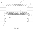
FIG. 4B is a cross-sectional view of the embodiment of the system for bonding films of this invention, showing the deformable roller and the bonding roller pressing the first film and the second film simultaneously. -
FIGS. 5A and 5B are schematic diagrams of another embodiment of the system for bonding films of this invention. -
FIG. 6 is a flow diagram of the method for preparing a composite film by using the system for bonding films of this invention. -
FIG. 1 is a schematic diagram of the embodiment of the system for bonding films of this invention. The system for bonding films includes afirst film 50, asecond film 40 including a plurality ofelements 41, afirst feed roller 31, asecond feed roller 32, abonding roller 21 and adeformable roller 22 including a deformableouter layer 221. - The
first film 50 is guided by thefirst feed roller 31 to thebonding roller 50, and thesecond film 40 is guided by thesecond feed roller 32 to thedeformable roller 22. Thebonding roller 21 receives thefirst film 50 and is configured to indirectly contact to thedeformable roller 22 via thefirst film 50 and thesecond film 40 for pressing thefirst film 50 to thesecond film 40. Also, thedeformable roller 22 receives thesecond film 40 and is configured to indirectly contact to thebonding roller 21 via thefirst film 50 and thesecond film 40 for pressing thesecond film 40 to thefirst film 50. The deformableouter layer 221 of thedeformable roller 22 produces enough deformation during pressing thesecond film 40 to fill the area not covered by the plurality ofelements 41 on thesecond film 40. Therefore, thesecond film 40 and thefirst film 50 can be bonded with each other to produce a composite film without wrinkles. The description here is only for illustration with drawings, and is not intended to limit the amount and the location of the rollers. In other embodiments, if there are more than three films to be bonded to each other, the number of feeding rollers will increase accordingly. - The
first film 50 has afirst surface 501 and asecond surface 502 opposed to thefirst surface 501. Thefirst surface 501 is configured to orientate to thesecond film 40, so that thefirst surface 501 of thefirst film 50 is bonded to thesecond film 40. The thickness of thefirst film 50 may range from several microns to thousands of microns. Thefirst film 50 is PET (polyethylene terephthalate) or other plastic film with sufficient stiffness. - The
second film 40 has afirst surface 401 and asecond surface 402 opposed to thefirst surface 401. Thefirst surface 401 is configured to orientate to thefirst film 50, so that thefirst surface 401 of thesecond film 40 is bonded to thefirst surface 501 of thefirst film 50. The thickness of thesecond film 50 is about 0.001-0.02 millimeters (mm), preferably 0.004-0.006 mm. Thesecond film 40 is a metal film, such as a copper thin film or an aluminum thin film, etc. There have a plurality ofelements 41 on thesecond surface 402 of thesecond film 40 and the areas not covered by the plurality ofelements 41. In the areas not covered by the plurality ofelements 41, it is defined agap space 411 between twoadjacent elements 41. Therefore, there has at least onegap space 411 on thesecond surface 402 of thesecond film 40. The height of eachelements 41 is 40-200 micrometers. The distance between twoadjacent elements 41 is 2-150 millimeters. Theelements 41 are the components related to batteries, such as a positive active material layer, a negative active material layer, a glue frame and etc. Also, eachelements 41 may be the same or different components related to batteries. In one embodiment, theelements 41 may be the one of the positive active material layer, the negative active material layer or the glue frame. In another embodiment, theelements 41 may be the positive active material layer, the negative active material layer or the glue frame respectively. - In an embodiment, an adhesive substance is applied to the
first surface 501 of thefirst film 50 for bonding to thefirst surface 401 of thesecond film 40. The adhesive substance may be an adhesive glue or an adhesive gel. - In this invention, the
second film 40 is with a stiffness less than that of thefirst film 50. The stiffness is the ability for resisting bending of a thin film. Therefore, in this invention, thesecond film 40 is easier to generate wrinkles than thefirst film 50, due to the stiffness of thesecond film 40 is less than that of thefirst film 50. - The
bonding roller 21 receives thefirst film 50 guided by thefirst feed roller 31 and continually contacts to thesecond surface 502 of thefirst film 50. Thebonding roller 21 may be all kinds of hollow or solid roller, such as a steel roller, a rubber coated roller. Thebonding roller 21 has a Shore A hardness greater than that of thedeformable roller 22. - The
deformable roller 22 is disposed adjacent thebonding roller 21. Thedeformable roller 22 receives thesecond film 40 guided by thesecond feed roller 32. Thedeformable roller 22 has a deformableouter layer 221 and aninner roller 222 covered by the deformableouter layer 221, as shown inFIG. 2 . A thickness of the deformableouter layer 221 is 1-4 millimeters, which is made of soft polymer or is porous. For example, the polymer is, but not limited to, rubber. The diameter of theinner roller 222 is 50-250 millimeters3. Theinner roller 222 may be a steel or an aluminum roller which is solid or hollow. A hardness of the deformableouter layer 221 is from 15 Shore A to 50 Shore A. - As shown in
FIG. 3 , there have a plurality ofelements 41 on thesecond surface 402 of thesecond film 40. Since theelements 41 have a certain thickness and weight, they have a certain mechanical strength. Therefore, the stiffness of the areas, which are covered by theelements 41 on thesecond film 40 can be enhanced. For the areas, which are not covered by theelements 41 on thesecond film 40, it is easier to generate wrinkles, due to not supported by theelements 41, especially in thegap space 411 between twoadjacent elements 41 on thesecond surface 402. Therefore, in this invention, the deformableouter layer 221 of thedeformable roller 22 produces enough deformation during bonding films to fill and press the areas not covered by the plurality ofelements 41 on thesecond surface 402 of thesecond film 40. In particularly, the deformableouter layer 221 produces enough deformation by against theelements 41 on both sides to fill thegap space 411 to enhance the mechanical strength on this area during bonding. Therefore, when thedeformable roller 22 pressing thesecond film 40 and thebonding roller 21 pressing thefirst film 50, thefirst film 50 and thesecond film 40 can be bonded flatly with each other to produce a composite film without wrinkles. -
FIG. 4A is a schematic diagram showing thedeformable roller 22 and thebonding roller 21 pressing thefirst film 50 and thesecond film 40 respectively. Thebonding roller 21 presses thefirst surface 501 of thefirst film 50 toward to thefirst surface 401 of thesecond film 40. Also, thedeformable roller 22 presses thefirst surface 401 of thesecond film 40 toward to thefirst surface 501 of thefirst film 50 to make thefirst film 50 and thesecond film 40 be bonded with each other. In the figure, theelements 41 on thesecond surface 402 of thesecond film 40 is arranged in a matrix. It can also be in an irregular arrangement. -
FIG. 4B is a cross-sectional view taken along a central line of a rolling axis of thedeformable roller 22 and a central line of a rolling axis of thebonding roller 21. InFIG. 4B , thebonding roller 21 presses thefirst surface 501 of thefirst film 50 toward to thefirst surface 401 of thesecond film 40, and thedeformable roller 22 presses thefirst surface 401 of thesecond film 40 toward to thefirst surface 501 of thefirst film 50. In details, the deformableouter layer 221 of thedeformable roller 22 produces enough deformation to fill and press the areas not covered by the plurality ofelements 41 on thesecond surface 402 of thesecond film 40. In particularly, the deformableouter layer 221 produces enough deformation to fill thegap space 411 between theadjacent elements 41. Therefore, thefirst film 50 and thesecond film 40 can be bonded to produce a composite film without wrinkles. - The deformable
outer layer 221 may has a plurality ofholes 2211 inside, seeFIG. 5A , or have a plurality ofpores 2212 on the outer surface, seeFIG. 5B . These types of the deformableouter layer 221 can produce enough deformation to fill thegap space 411 between theadjacent elements 41 during bonding. -
FIG. 6 is a flow diagram of the method for preparing a composite film by using the system for bonding films of this invention. The method for preparing the composite film includes the steps of: - in the step S601, providing a
first film 50; - in the step S602, providing a
second film 40; - in the step S603, guiding the
first film 50 to thebonding roller 21 by thefirst feed roller 31 and guiding thesecond film 40 to thedeformable roller 22 by thesecond feed roller 32; - in the step S604, receiving the
first film 50 by thebonding roller 21 and pressing thefirst surface 501 of thefirst film 50 toward to thefirst surface 401 of thesecond film 40, and receiving thesecond film 40 by thedeformable roller 22 and pressing thefirst surface 401 of thesecond film 40 toward to thefirst surface 501 of thefirst film 50, wherein the deformableouter layer 221 of thedeformable roller 22 produces deformation to fill the at least onegap space 411 on thesecond surface 402 of thesecond film 40; and - in the step S605, obtaining the composite film that the
first film 50 is bonded to thesecond film 40. - Accordingly, the present invention provides a system for bonding films and method for preparing a composite film using the same to solve the problems of generating wrinkles when the film without sufficient stiffness bond to another film, especially suitable for the film without sufficient stiffness having a plurality of elements thereon. The system of this invention includes the deformable roller, which produces enough deformation during bonding to fill the gap space between the elements of the film without sufficient stiffness. Therefore, the film without sufficient stiffness and another film can be bonded with each other flatly to produce a composite film without wrinkles.
- The invention being thus described, it will be obvious that the same may be varied in many ways. Such variations are not to be regarded as a departure from the spirit and scope of the invention, and all such modifications as would be obvious to one skilled in the art are intended to be included within the scope of the following claims.
Claims (10)
- A system for bonding films, comprising:a first film (50), having a first surface (501) and a second surface (502) opposed to the first surface (501);a second film (40), with a stiffness less than that of the first film (50) and having a first surface (401) and a second surface (402) opposed to the first surface (401), wherein the first surface (401) of the second film (40) is configured to orientate to the first surface (501) of the first film (50) and the second surface (402) of the second film (40) includes a plurality of elements (41) and at least one gap space (411) uncovered by the elements (41);a bonding roller (21), configured to contact the second surface (502) of the first film (50); anda deformable roller (22), configured to contact the second surface (402) of the second film (40) and disposed adjacent the bonding roller (21), wherein the deformable roller (22) has a deformable outer layer (221) and the deformable roller (22) produces deformation to fill the at least one gap space (411) on the second surface (402) of the second film (40);wherein the bonding roller (21) is configured to indirectly contact to the deformable roller (22) via the first film (50) and the second film (40), and the deformable roller (22) is configured to indirectly contact to the bonding roller (21) via the first film (50) and the second film (40).
- The system for bonding films of claim 1, wherein each of the elements (41) is a component related to batteries.
- The system for bonding films of claim 1, wherein a distance between two adjacent elements (41) is 2-150 millimeters.
- The system for bonding films of claim 1, wherein the deformable roller (22) includes an inner roller (222) covered by the deformable outer layer (221).
- The system for bonding films of claim 1, wherein a hardness of the deformable outer layer (221) of the deformable roller (22) is from 15 Shore A to 50 Shore A.
- The system for bonding films of claim 5, wherein a thickness of the deformable outer layer (221) of the deformable roller (22) is 1-4 millimeters.
- The system for bonding films of claim 6, wherein the deformable outer layer (221) of the deformable roller (22) is made of a polymer.
- The system for bonding films of claim 7, wherein the deformable outer layer (221) of the deformable roller (22) is porous.
- The system for bonding films of claim 1, wherein the bonding roller (21) has a Shore A hardness greater than that of the deformable roller (22).
- A method for preparing a composite film by using the system for bonding films of claim 1, comprising the steps of:receiving the first film (50) by the bonding roller (21) and pressing the first surface (501) of the first film (50) toward to the first surface (401) of the second film (40), and receiving the second film (40) by the deformable roller (22) and pressing the first surface (401) of the second film (40) toward to the first surface (501) of the first film (50), wherein the deformable outer layer (221) of the deformable roller (22) produces deformation to fill the at least one gap space (411) on the second surface (402) of the second film (40); andobtaining the composite film that the first film (50) is bonded to the second film (40).
Applications Claiming Priority (1)
| Application Number | Priority Date | Filing Date | Title |
|---|---|---|---|
| TW112135640A TWI879100B (en) | 2023-09-19 | 2023-09-19 | System for bonding films and method for preparing composite film using the same |
Publications (2)
| Publication Number | Publication Date |
|---|---|
| EP4527620A1 true EP4527620A1 (en) | 2025-03-26 |
| EP4527620B1 EP4527620B1 (en) | 2026-04-08 |
Family
ID=92708396
Family Applications (1)
| Application Number | Title | Priority Date | Filing Date |
|---|---|---|---|
| EP24198669.4A Active EP4527620B1 (en) | 2023-09-19 | 2024-09-05 | System for bonding films and method for preparing composite film using the same |
Country Status (7)
| Country | Link |
|---|---|
| US (1) | US20250091299A1 (en) |
| EP (1) | EP4527620B1 (en) |
| JP (1) | JP7815370B2 (en) |
| KR (1) | KR20250042110A (en) |
| CN (1) | CN119659136A (en) |
| CA (1) | CA3252602A1 (en) |
| TW (1) | TWI879100B (en) |
Citations (7)
| Publication number | Priority date | Publication date | Assignee | Title |
|---|---|---|---|---|
| EP1511578B1 (en) * | 2002-06-11 | 2008-11-19 | 3M Innovative Properties Company | Method of conforming an adherent film to a substrate by application of vacuum |
| WO2011093427A1 (en) | 2010-01-29 | 2011-08-04 | 新日鐵化学株式会社 | Method for manufacturing a laminate with one metal-plated side |
| JP2013095117A (en) * | 2011-11-04 | 2013-05-20 | Meiko Shokai Co Ltd | Laminator |
| US20170263970A1 (en) * | 2014-09-18 | 2017-09-14 | Sekisui Chemical Co., Ltd. | Method for manufacturing secondary battery |
| JP2022052248A (en) * | 2020-09-23 | 2022-04-04 | 凸版印刷株式会社 | Laminating apparatus and film laminate manufacturing method |
| KR20220091399A (en) * | 2020-12-23 | 2022-06-30 | 주식회사 엘지에너지솔루션 | Manufacturing method and apparatus for unit cell |
| EP3845381B1 (en) * | 2019-12-30 | 2023-04-12 | Prologium Technology Co., Ltd. | Air-floating thin film bonding apparatus |
Family Cites Families (9)
| Publication number | Priority date | Publication date | Assignee | Title |
|---|---|---|---|---|
| JPS62153986A (en) * | 1985-12-27 | 1987-07-08 | Canon Inc | Method for manufacturing an elastic rotating body and the elastic rotating body |
| JPH0565525U (en) * | 1992-02-19 | 1993-08-31 | 静岡技研産機株式会社 | Curved laminating machine |
| JPH10157275A (en) * | 1996-11-29 | 1998-06-16 | Dainippon Printing Co Ltd | Manufacturing method of decorative board |
| JP2000211090A (en) | 1999-01-26 | 2000-08-02 | Dainippon Printing Co Ltd | Method of manufacturing cosmetic sheet |
| TWM299605U (en) * | 2006-04-27 | 2006-10-21 | Thinflex Corp | Hot rolling equipment for laminated materials |
| TWI686291B (en) | 2015-04-20 | 2020-03-01 | 日商可樂麗股份有限公司 | Manufacturing method of metal-clad laminate and metal-clad laminate using the same |
| CN104760395B (en) * | 2015-05-06 | 2017-03-08 | 合肥京东方光电科技有限公司 | A kind of film pressing device and pressing film method |
| JP6868433B2 (en) | 2017-03-27 | 2021-05-12 | 株式会社Screenラミナテック | Laminating device and laminating method |
| US11271212B1 (en) * | 2021-04-02 | 2022-03-08 | Ses Holdings Pte. Ltd. | Anode fabrication by pattern lamination, anodes made thereby, and electrochemical devices incorporating such anodes |
-
2023
- 2023-09-19 TW TW112135640A patent/TWI879100B/en active
-
2024
- 2024-08-20 CA CA3252602A patent/CA3252602A1/en active Pending
- 2024-08-22 US US18/812,150 patent/US20250091299A1/en active Pending
- 2024-08-29 CN CN202411197783.7A patent/CN119659136A/en active Pending
- 2024-09-05 EP EP24198669.4A patent/EP4527620B1/en active Active
- 2024-09-18 JP JP2024161161A patent/JP7815370B2/en active Active
- 2024-09-19 KR KR1020240126474A patent/KR20250042110A/en active Pending
Patent Citations (7)
| Publication number | Priority date | Publication date | Assignee | Title |
|---|---|---|---|---|
| EP1511578B1 (en) * | 2002-06-11 | 2008-11-19 | 3M Innovative Properties Company | Method of conforming an adherent film to a substrate by application of vacuum |
| WO2011093427A1 (en) | 2010-01-29 | 2011-08-04 | 新日鐵化学株式会社 | Method for manufacturing a laminate with one metal-plated side |
| JP2013095117A (en) * | 2011-11-04 | 2013-05-20 | Meiko Shokai Co Ltd | Laminator |
| US20170263970A1 (en) * | 2014-09-18 | 2017-09-14 | Sekisui Chemical Co., Ltd. | Method for manufacturing secondary battery |
| EP3845381B1 (en) * | 2019-12-30 | 2023-04-12 | Prologium Technology Co., Ltd. | Air-floating thin film bonding apparatus |
| JP2022052248A (en) * | 2020-09-23 | 2022-04-04 | 凸版印刷株式会社 | Laminating apparatus and film laminate manufacturing method |
| KR20220091399A (en) * | 2020-12-23 | 2022-06-30 | 주식회사 엘지에너지솔루션 | Manufacturing method and apparatus for unit cell |
Also Published As
| Publication number | Publication date |
|---|---|
| TW202513327A (en) | 2025-04-01 |
| KR20250042110A (en) | 2025-03-26 |
| US20250091299A1 (en) | 2025-03-20 |
| EP4527620B1 (en) | 2026-04-08 |
| CN119659136A (en) | 2025-03-21 |
| TWI879100B (en) | 2025-04-01 |
| JP7815370B2 (en) | 2026-02-17 |
| CA3252602A1 (en) | 2025-11-29 |
| JP2025044184A (en) | 2025-04-01 |
Similar Documents
| Publication | Publication Date | Title |
|---|---|---|
| EP3845381A2 (en) | Air-floating thin film bonding apparatus and its air-floating roller | |
| EP3130432B1 (en) | Method and device for manufacturing microporous metal foil | |
| EP2383113B1 (en) | Metal foil with carrier | |
| JP2004513809A (en) | Extrusion embossing method and system | |
| JP6883456B2 (en) | Manufacturing method of laminates and molded products | |
| EP4527620A1 (en) | System for bonding films and method for preparing composite film using the same | |
| EP0908295A2 (en) | Method of manufacturing laminated thermoplastic resin sheet and apparatus therefor | |
| CN112573269B (en) | Production system for foam die-cutting piece with relatively soft and relatively large foaming hole | |
| CN206394191U (en) | A kind of mould for plastics | |
| KR20230009141A (en) | Pouch Curling Prevention Device | |
| JP2002178046A (en) | Deep drawing method and deep drawing device | |
| US20230068234A1 (en) | Method for manufacturing ribbon piece | |
| CN113021921A (en) | Manufacturing method of inner shrinking rubber reinforced steel sheet | |
| CN210100697U (en) | Multilayer laminating device and soaking piece production system | |
| CN119820865B (en) | A composite process and composite system | |
| US20260128273A1 (en) | Laminating apparatus for laminating multilayer endless webs for producing energy cells | |
| JP5825508B2 (en) | IC card manufacturing apparatus and manufacturing method | |
| WO2018070905A1 (en) | Method for producing a multi-layer material by applying an extruded polymeric coating during calendering | |
| CN120432498A (en) | Positive electrode sheet, preparation method, system and battery thereof | |
| US8440038B2 (en) | Method for making a laminate | |
| CN115534009A (en) | A kind of die-cutting equipment and half-type die-cutting method | |
| JP2019036419A (en) | Crimping device and crimped body manufacturing method | |
| CN121246245A (en) | Glue forming die and method | |
| CN113736375A (en) | Method for solving adhesive tape displacement | |
| CN121697315A (en) | A non-embossing processing technology for conductive foam used in camera modules |
Legal Events
| Date | Code | Title | Description |
|---|---|---|---|
| PUAI | Public reference made under article 153(3) epc to a published international application that has entered the european phase |
Free format text: ORIGINAL CODE: 0009012 |
|
| STAA | Information on the status of an ep patent application or granted ep patent |
Free format text: STATUS: THE APPLICATION HAS BEEN PUBLISHED |
|
| AK | Designated contracting states |
Kind code of ref document: A1 Designated state(s): AL AT BE BG CH CY CZ DE DK EE ES FI FR GB GR HR HU IE IS IT LI LT LU LV MC ME MK MT NL NO PL PT RO RS SE SI SK SM TR |
|
| STAA | Information on the status of an ep patent application or granted ep patent |
Free format text: STATUS: REQUEST FOR EXAMINATION WAS MADE |
|
| 17P | Request for examination filed |
Effective date: 20250723 |
|
| GRAP | Despatch of communication of intention to grant a patent |
Free format text: ORIGINAL CODE: EPIDOSNIGR1 |
|
| STAA | Information on the status of an ep patent application or granted ep patent |
Free format text: STATUS: GRANT OF PATENT IS INTENDED |
|
| INTG | Intention to grant announced |
Effective date: 20251202 |
|
| GRAS | Grant fee paid |
Free format text: ORIGINAL CODE: EPIDOSNIGR3 |
|
| GRAA | (expected) grant |
Free format text: ORIGINAL CODE: 0009210 |
|
| STAA | Information on the status of an ep patent application or granted ep patent |
Free format text: STATUS: THE PATENT HAS BEEN GRANTED |
|
| AK | Designated contracting states |
Kind code of ref document: B1 Designated state(s): AL AT BE BG CH CY CZ DE DK EE ES FI FR GB GR HR HU IE IS IT LI LT LU LV MC ME MK MT NL NO PL PT RO RS SE SI SK SM TR |
|
| REG | Reference to a national code |
Ref country code: CH Ref legal event code: F10 Free format text: ST27 STATUS EVENT CODE: U-0-0-F10-F00 (AS PROVIDED BY THE NATIONAL OFFICE) Effective date: 20260408 Ref country code: GB Ref legal event code: FG4D |
|
| REG | Reference to a national code |
Ref country code: CH Ref legal event code: R17 Free format text: ST27 STATUS EVENT CODE: U-0-0-R10-R17 (AS PROVIDED BY THE NATIONAL OFFICE) Effective date: 20260410 |
|
| REG | Reference to a national code |
Ref country code: DE Ref legal event code: R096 Ref document number: 602024003811 Country of ref document: DE |