EP4527583A1 - Resin processing device, resin pellet production method, and resin material processing method - Google Patents
Resin processing device, resin pellet production method, and resin material processing method Download PDFInfo
- Publication number
- EP4527583A1 EP4527583A1 EP23826759.5A EP23826759A EP4527583A1 EP 4527583 A1 EP4527583 A1 EP 4527583A1 EP 23826759 A EP23826759 A EP 23826759A EP 4527583 A1 EP4527583 A1 EP 4527583A1
- Authority
- EP
- European Patent Office
- Prior art keywords
- cylinder
- resin
- extruder
- resin material
- supplied
- Prior art date
- Legal status (The legal status is an assumption and is not a legal conclusion. Google has not performed a legal analysis and makes no representation as to the accuracy of the status listed.)
- Pending
Links
Images




Classifications
-
- B—PERFORMING OPERATIONS; TRANSPORTING
- B29—WORKING OF PLASTICS; WORKING OF SUBSTANCES IN A PLASTIC STATE IN GENERAL
- B29C—SHAPING OR JOINING OF PLASTICS; SHAPING OF MATERIAL IN A PLASTIC STATE, NOT OTHERWISE PROVIDED FOR; AFTER-TREATMENT OF THE SHAPED PRODUCTS, e.g. REPAIRING
- B29C48/00—Extrusion moulding, i.e. expressing the moulding material through a die or nozzle which imparts the desired form; Apparatus therefor
- B29C48/25—Component parts, details or accessories; Auxiliary operations
- B29C48/78—Thermal treatment of the extrusion moulding material or of preformed parts or layers, e.g. by heating or cooling
- B29C48/875—Thermal treatment of the extrusion moulding material or of preformed parts or layers, e.g. by heating or cooling for achieving a non-uniform temperature distribution, e.g. using barrels having both cooling and heating zones
-
- B—PERFORMING OPERATIONS; TRANSPORTING
- B29—WORKING OF PLASTICS; WORKING OF SUBSTANCES IN A PLASTIC STATE IN GENERAL
- B29C—SHAPING OR JOINING OF PLASTICS; SHAPING OF MATERIAL IN A PLASTIC STATE, NOT OTHERWISE PROVIDED FOR; AFTER-TREATMENT OF THE SHAPED PRODUCTS, e.g. REPAIRING
- B29C48/00—Extrusion moulding, i.e. expressing the moulding material through a die or nozzle which imparts the desired form; Apparatus therefor
- B29C48/25—Component parts, details or accessories; Auxiliary operations
- B29C48/36—Means for plasticising or homogenising the moulding material or forcing it through the nozzle or die
- B29C48/375—Plasticisers, homogenisers or feeders comprising two or more stages
- B29C48/385—Plasticisers, homogenisers or feeders comprising two or more stages using two or more serially arranged screws in separate barrels
-
- B—PERFORMING OPERATIONS; TRANSPORTING
- B29—WORKING OF PLASTICS; WORKING OF SUBSTANCES IN A PLASTIC STATE IN GENERAL
- B29B—PREPARATION OR PRETREATMENT OF THE MATERIAL TO BE SHAPED; MAKING GRANULES OR PREFORMS; RECOVERY OF PLASTICS OR OTHER CONSTITUENTS OF WASTE MATERIAL CONTAINING PLASTICS
- B29B17/00—Recovery of plastics or other constituents of waste material containing plastics
- B29B17/04—Disintegrating plastics, e.g. by milling
-
- B—PERFORMING OPERATIONS; TRANSPORTING
- B29—WORKING OF PLASTICS; WORKING OF SUBSTANCES IN A PLASTIC STATE IN GENERAL
- B29B—PREPARATION OR PRETREATMENT OF THE MATERIAL TO BE SHAPED; MAKING GRANULES OR PREFORMS; RECOVERY OF PLASTICS OR OTHER CONSTITUENTS OF WASTE MATERIAL CONTAINING PLASTICS
- B29B9/00—Making granules
- B29B9/12—Making granules characterised by structure or composition
-
- B—PERFORMING OPERATIONS; TRANSPORTING
- B29—WORKING OF PLASTICS; WORKING OF SUBSTANCES IN A PLASTIC STATE IN GENERAL
- B29C—SHAPING OR JOINING OF PLASTICS; SHAPING OF MATERIAL IN A PLASTIC STATE, NOT OTHERWISE PROVIDED FOR; AFTER-TREATMENT OF THE SHAPED PRODUCTS, e.g. REPAIRING
- B29C48/00—Extrusion moulding, i.e. expressing the moulding material through a die or nozzle which imparts the desired form; Apparatus therefor
- B29C48/001—Combinations of extrusion moulding with other shaping operations
- B29C48/0022—Combinations of extrusion moulding with other shaping operations combined with cutting
-
- B—PERFORMING OPERATIONS; TRANSPORTING
- B29—WORKING OF PLASTICS; WORKING OF SUBSTANCES IN A PLASTIC STATE IN GENERAL
- B29C—SHAPING OR JOINING OF PLASTICS; SHAPING OF MATERIAL IN A PLASTIC STATE, NOT OTHERWISE PROVIDED FOR; AFTER-TREATMENT OF THE SHAPED PRODUCTS, e.g. REPAIRING
- B29C48/00—Extrusion moulding, i.e. expressing the moulding material through a die or nozzle which imparts the desired form; Apparatus therefor
- B29C48/022—Extrusion moulding, i.e. expressing the moulding material through a die or nozzle which imparts the desired form; Apparatus therefor characterised by the choice of material
- B29C48/023—Extruding materials comprising incompatible ingredients
-
- B—PERFORMING OPERATIONS; TRANSPORTING
- B29—WORKING OF PLASTICS; WORKING OF SUBSTANCES IN A PLASTIC STATE IN GENERAL
- B29C—SHAPING OR JOINING OF PLASTICS; SHAPING OF MATERIAL IN A PLASTIC STATE, NOT OTHERWISE PROVIDED FOR; AFTER-TREATMENT OF THE SHAPED PRODUCTS, e.g. REPAIRING
- B29C48/00—Extrusion moulding, i.e. expressing the moulding material through a die or nozzle which imparts the desired form; Apparatus therefor
- B29C48/03—Extrusion moulding, i.e. expressing the moulding material through a die or nozzle which imparts the desired form; Apparatus therefor characterised by the shape of the extruded material at extrusion
- B29C48/04—Particle-shaped
-
- B—PERFORMING OPERATIONS; TRANSPORTING
- B29—WORKING OF PLASTICS; WORKING OF SUBSTANCES IN A PLASTIC STATE IN GENERAL
- B29C—SHAPING OR JOINING OF PLASTICS; SHAPING OF MATERIAL IN A PLASTIC STATE, NOT OTHERWISE PROVIDED FOR; AFTER-TREATMENT OF THE SHAPED PRODUCTS, e.g. REPAIRING
- B29C48/00—Extrusion moulding, i.e. expressing the moulding material through a die or nozzle which imparts the desired form; Apparatus therefor
- B29C48/25—Component parts, details or accessories; Auxiliary operations
- B29C48/285—Feeding the extrusion material to the extruder
- B29C48/297—Feeding the extrusion material to the extruder at several locations, e.g. using several hoppers or using a separate additive feeding
-
- B—PERFORMING OPERATIONS; TRANSPORTING
- B29—WORKING OF PLASTICS; WORKING OF SUBSTANCES IN A PLASTIC STATE IN GENERAL
- B29C—SHAPING OR JOINING OF PLASTICS; SHAPING OF MATERIAL IN A PLASTIC STATE, NOT OTHERWISE PROVIDED FOR; AFTER-TREATMENT OF THE SHAPED PRODUCTS, e.g. REPAIRING
- B29C48/00—Extrusion moulding, i.e. expressing the moulding material through a die or nozzle which imparts the desired form; Apparatus therefor
- B29C48/25—Component parts, details or accessories; Auxiliary operations
- B29C48/36—Means for plasticising or homogenising the moulding material or forcing it through the nozzle or die
- B29C48/375—Plasticisers, homogenisers or feeders comprising two or more stages
- B29C48/387—Plasticisers, homogenisers or feeders comprising two or more stages using a screw extruder and a gear pump
-
- B—PERFORMING OPERATIONS; TRANSPORTING
- B29—WORKING OF PLASTICS; WORKING OF SUBSTANCES IN A PLASTIC STATE IN GENERAL
- B29C—SHAPING OR JOINING OF PLASTICS; SHAPING OF MATERIAL IN A PLASTIC STATE, NOT OTHERWISE PROVIDED FOR; AFTER-TREATMENT OF THE SHAPED PRODUCTS, e.g. REPAIRING
- B29C48/00—Extrusion moulding, i.e. expressing the moulding material through a die or nozzle which imparts the desired form; Apparatus therefor
- B29C48/25—Component parts, details or accessories; Auxiliary operations
- B29C48/36—Means for plasticising or homogenising the moulding material or forcing it through the nozzle or die
- B29C48/375—Plasticisers, homogenisers or feeders comprising two or more stages
- B29C48/39—Plasticisers, homogenisers or feeders comprising two or more stages a first extruder feeding the melt into an intermediate location of a second extruder
-
- B—PERFORMING OPERATIONS; TRANSPORTING
- B29—WORKING OF PLASTICS; WORKING OF SUBSTANCES IN A PLASTIC STATE IN GENERAL
- B29C—SHAPING OR JOINING OF PLASTICS; SHAPING OF MATERIAL IN A PLASTIC STATE, NOT OTHERWISE PROVIDED FOR; AFTER-TREATMENT OF THE SHAPED PRODUCTS, e.g. REPAIRING
- B29C48/00—Extrusion moulding, i.e. expressing the moulding material through a die or nozzle which imparts the desired form; Apparatus therefor
- B29C48/25—Component parts, details or accessories; Auxiliary operations
- B29C48/36—Means for plasticising or homogenising the moulding material or forcing it through the nozzle or die
- B29C48/50—Details of extruders
- B29C48/76—Venting, drying means; Degassing means
-
- B—PERFORMING OPERATIONS; TRANSPORTING
- B29—WORKING OF PLASTICS; WORKING OF SUBSTANCES IN A PLASTIC STATE IN GENERAL
- B29C—SHAPING OR JOINING OF PLASTICS; SHAPING OF MATERIAL IN A PLASTIC STATE, NOT OTHERWISE PROVIDED FOR; AFTER-TREATMENT OF THE SHAPED PRODUCTS, e.g. REPAIRING
- B29C48/00—Extrusion moulding, i.e. expressing the moulding material through a die or nozzle which imparts the desired form; Apparatus therefor
- B29C48/25—Component parts, details or accessories; Auxiliary operations
- B29C48/78—Thermal treatment of the extrusion moulding material or of preformed parts or layers, e.g. by heating or cooling
- B29C48/80—Thermal treatment of the extrusion moulding material or of preformed parts or layers, e.g. by heating or cooling at the plasticising zone, e.g. by heating cylinders
- B29C48/83—Heating or cooling the cylinders
- B29C48/832—Heating
-
- B—PERFORMING OPERATIONS; TRANSPORTING
- B29—WORKING OF PLASTICS; WORKING OF SUBSTANCES IN A PLASTIC STATE IN GENERAL
- B29C—SHAPING OR JOINING OF PLASTICS; SHAPING OF MATERIAL IN A PLASTIC STATE, NOT OTHERWISE PROVIDED FOR; AFTER-TREATMENT OF THE SHAPED PRODUCTS, e.g. REPAIRING
- B29C48/00—Extrusion moulding, i.e. expressing the moulding material through a die or nozzle which imparts the desired form; Apparatus therefor
- B29C48/25—Component parts, details or accessories; Auxiliary operations
- B29C48/92—Measuring, controlling or regulating
-
- C—CHEMISTRY; METALLURGY
- C08—ORGANIC MACROMOLECULAR COMPOUNDS; THEIR PREPARATION OR CHEMICAL WORKING-UP; COMPOSITIONS BASED THEREON
- C08J—WORKING-UP; GENERAL PROCESSES OF COMPOUNDING; AFTER-TREATMENT NOT COVERED BY SUBCLASSES C08B, C08C, C08F, C08G or C08H
- C08J11/00—Recovery or working-up of waste materials
- C08J11/04—Recovery or working-up of waste materials of polymers
- C08J11/10—Recovery or working-up of waste materials of polymers by chemically breaking down the molecular chains of polymers or breaking of crosslinks, e.g. devulcanisation
- C08J11/12—Recovery or working-up of waste materials of polymers by chemically breaking down the molecular chains of polymers or breaking of crosslinks, e.g. devulcanisation by dry-heat treatment only
-
- B—PERFORMING OPERATIONS; TRANSPORTING
- B29—WORKING OF PLASTICS; WORKING OF SUBSTANCES IN A PLASTIC STATE IN GENERAL
- B29B—PREPARATION OR PRETREATMENT OF THE MATERIAL TO BE SHAPED; MAKING GRANULES OR PREFORMS; RECOVERY OF PLASTICS OR OTHER CONSTITUENTS OF WASTE MATERIAL CONTAINING PLASTICS
- B29B17/00—Recovery of plastics or other constituents of waste material containing plastics
- B29B17/04—Disintegrating plastics, e.g. by milling
- B29B2017/0424—Specific disintegrating techniques; devices therefor
- B29B2017/0496—Pyrolysing the materials
-
- B—PERFORMING OPERATIONS; TRANSPORTING
- B29—WORKING OF PLASTICS; WORKING OF SUBSTANCES IN A PLASTIC STATE IN GENERAL
- B29B—PREPARATION OR PRETREATMENT OF THE MATERIAL TO BE SHAPED; MAKING GRANULES OR PREFORMS; RECOVERY OF PLASTICS OR OTHER CONSTITUENTS OF WASTE MATERIAL CONTAINING PLASTICS
- B29B9/00—Making granules
- B29B9/02—Making granules by dividing preformed material
- B29B9/06—Making granules by dividing preformed material in the form of filamentary material, e.g. combined with extrusion
-
- B—PERFORMING OPERATIONS; TRANSPORTING
- B29—WORKING OF PLASTICS; WORKING OF SUBSTANCES IN A PLASTIC STATE IN GENERAL
- B29C—SHAPING OR JOINING OF PLASTICS; SHAPING OF MATERIAL IN A PLASTIC STATE, NOT OTHERWISE PROVIDED FOR; AFTER-TREATMENT OF THE SHAPED PRODUCTS, e.g. REPAIRING
- B29C2793/00—Shaping techniques involving a cutting or machining operation
- B29C2793/0027—Cutting off
-
- B—PERFORMING OPERATIONS; TRANSPORTING
- B29—WORKING OF PLASTICS; WORKING OF SUBSTANCES IN A PLASTIC STATE IN GENERAL
- B29C—SHAPING OR JOINING OF PLASTICS; SHAPING OF MATERIAL IN A PLASTIC STATE, NOT OTHERWISE PROVIDED FOR; AFTER-TREATMENT OF THE SHAPED PRODUCTS, e.g. REPAIRING
- B29C2793/00—Shaping techniques involving a cutting or machining operation
- B29C2793/009—Shaping techniques involving a cutting or machining operation after shaping
-
- B—PERFORMING OPERATIONS; TRANSPORTING
- B29—WORKING OF PLASTICS; WORKING OF SUBSTANCES IN A PLASTIC STATE IN GENERAL
- B29C—SHAPING OR JOINING OF PLASTICS; SHAPING OF MATERIAL IN A PLASTIC STATE, NOT OTHERWISE PROVIDED FOR; AFTER-TREATMENT OF THE SHAPED PRODUCTS, e.g. REPAIRING
- B29C2948/00—Indexing scheme relating to extrusion moulding
- B29C2948/92—Measuring, controlling or regulating
- B29C2948/92504—Controlled parameter
- B29C2948/92704—Temperature
-
- B—PERFORMING OPERATIONS; TRANSPORTING
- B29—WORKING OF PLASTICS; WORKING OF SUBSTANCES IN A PLASTIC STATE IN GENERAL
- B29C—SHAPING OR JOINING OF PLASTICS; SHAPING OF MATERIAL IN A PLASTIC STATE, NOT OTHERWISE PROVIDED FOR; AFTER-TREATMENT OF THE SHAPED PRODUCTS, e.g. REPAIRING
- B29C48/00—Extrusion moulding, i.e. expressing the moulding material through a die or nozzle which imparts the desired form; Apparatus therefor
- B29C48/03—Extrusion moulding, i.e. expressing the moulding material through a die or nozzle which imparts the desired form; Apparatus therefor characterised by the shape of the extruded material at extrusion
- B29C48/05—Filamentary, e.g. strands
-
- B—PERFORMING OPERATIONS; TRANSPORTING
- B29—WORKING OF PLASTICS; WORKING OF SUBSTANCES IN A PLASTIC STATE IN GENERAL
- B29C—SHAPING OR JOINING OF PLASTICS; SHAPING OF MATERIAL IN A PLASTIC STATE, NOT OTHERWISE PROVIDED FOR; AFTER-TREATMENT OF THE SHAPED PRODUCTS, e.g. REPAIRING
- B29C48/00—Extrusion moulding, i.e. expressing the moulding material through a die or nozzle which imparts the desired form; Apparatus therefor
- B29C48/25—Component parts, details or accessories; Auxiliary operations
- B29C48/36—Means for plasticising or homogenising the moulding material or forcing it through the nozzle or die
- B29C48/50—Details of extruders
- B29C48/505—Screws
- B29C48/57—Screws provided with kneading disc-like elements, e.g. with oval-shaped elements
-
- B—PERFORMING OPERATIONS; TRANSPORTING
- B29—WORKING OF PLASTICS; WORKING OF SUBSTANCES IN A PLASTIC STATE IN GENERAL
- B29C—SHAPING OR JOINING OF PLASTICS; SHAPING OF MATERIAL IN A PLASTIC STATE, NOT OTHERWISE PROVIDED FOR; AFTER-TREATMENT OF THE SHAPED PRODUCTS, e.g. REPAIRING
- B29C48/00—Extrusion moulding, i.e. expressing the moulding material through a die or nozzle which imparts the desired form; Apparatus therefor
- B29C48/25—Component parts, details or accessories; Auxiliary operations
- B29C48/36—Means for plasticising or homogenising the moulding material or forcing it through the nozzle or die
- B29C48/50—Details of extruders
- B29C48/76—Venting, drying means; Degassing means
- B29C48/765—Venting, drying means; Degassing means in the extruder apparatus
- B29C48/766—Venting, drying means; Degassing means in the extruder apparatus in screw extruders
- B29C48/767—Venting, drying means; Degassing means in the extruder apparatus in screw extruders through a degassing opening of a barrel
-
- B—PERFORMING OPERATIONS; TRANSPORTING
- B29—WORKING OF PLASTICS; WORKING OF SUBSTANCES IN A PLASTIC STATE IN GENERAL
- B29C—SHAPING OR JOINING OF PLASTICS; SHAPING OF MATERIAL IN A PLASTIC STATE, NOT OTHERWISE PROVIDED FOR; AFTER-TREATMENT OF THE SHAPED PRODUCTS, e.g. REPAIRING
- B29C48/00—Extrusion moulding, i.e. expressing the moulding material through a die or nozzle which imparts the desired form; Apparatus therefor
- B29C48/25—Component parts, details or accessories; Auxiliary operations
- B29C48/78—Thermal treatment of the extrusion moulding material or of preformed parts or layers, e.g. by heating or cooling
- B29C48/80—Thermal treatment of the extrusion moulding material or of preformed parts or layers, e.g. by heating or cooling at the plasticising zone, e.g. by heating cylinders
- B29C48/802—Heating
-
- B—PERFORMING OPERATIONS; TRANSPORTING
- B29—WORKING OF PLASTICS; WORKING OF SUBSTANCES IN A PLASTIC STATE IN GENERAL
- B29C—SHAPING OR JOINING OF PLASTICS; SHAPING OF MATERIAL IN A PLASTIC STATE, NOT OTHERWISE PROVIDED FOR; AFTER-TREATMENT OF THE SHAPED PRODUCTS, e.g. REPAIRING
- B29C48/00—Extrusion moulding, i.e. expressing the moulding material through a die or nozzle which imparts the desired form; Apparatus therefor
- B29C48/25—Component parts, details or accessories; Auxiliary operations
- B29C48/88—Thermal treatment of the stream of extruded material, e.g. cooling
- B29C48/919—Thermal treatment of the stream of extruded material, e.g. cooling using a bath, e.g. extruding into an open bath to coagulate or cool the material
-
- B—PERFORMING OPERATIONS; TRANSPORTING
- B29—WORKING OF PLASTICS; WORKING OF SUBSTANCES IN A PLASTIC STATE IN GENERAL
- B29K—INDEXING SCHEME ASSOCIATED WITH SUBCLASSES B29B, B29C OR B29D, RELATING TO MOULDING MATERIALS OR TO MATERIALS FOR MOULDS, REINFORCEMENTS, FILLERS OR PREFORMED PARTS, e.g. INSERTS
- B29K2105/00—Condition, form or state of moulded material or of the material to be shaped
- B29K2105/26—Scrap or recycled material
-
- Y—GENERAL TAGGING OF NEW TECHNOLOGICAL DEVELOPMENTS; GENERAL TAGGING OF CROSS-SECTIONAL TECHNOLOGIES SPANNING OVER SEVERAL SECTIONS OF THE IPC; TECHNICAL SUBJECTS COVERED BY FORMER USPC CROSS-REFERENCE ART COLLECTIONS [XRACs] AND DIGESTS
- Y02—TECHNOLOGIES OR APPLICATIONS FOR MITIGATION OR ADAPTATION AGAINST CLIMATE CHANGE
- Y02W—CLIMATE CHANGE MITIGATION TECHNOLOGIES RELATED TO WASTEWATER TREATMENT OR WASTE MANAGEMENT
- Y02W30/00—Technologies for solid waste management
- Y02W30/20—Waste processing or separation
-
- Y—GENERAL TAGGING OF NEW TECHNOLOGICAL DEVELOPMENTS; GENERAL TAGGING OF CROSS-SECTIONAL TECHNOLOGIES SPANNING OVER SEVERAL SECTIONS OF THE IPC; TECHNICAL SUBJECTS COVERED BY FORMER USPC CROSS-REFERENCE ART COLLECTIONS [XRACs] AND DIGESTS
- Y02—TECHNOLOGIES OR APPLICATIONS FOR MITIGATION OR ADAPTATION AGAINST CLIMATE CHANGE
- Y02W—CLIMATE CHANGE MITIGATION TECHNOLOGIES RELATED TO WASTEWATER TREATMENT OR WASTE MANAGEMENT
- Y02W30/00—Technologies for solid waste management
- Y02W30/50—Reuse, recycling or recovery technologies
- Y02W30/62—Plastics recycling; Rubber recycling
Definitions
- the present invention relates to a resin processing apparatus, a method of manufacturing resin pellets, and a method of processing a resin material.
- Patent Document 1 Japanese Unexamined Patent Application Publication No. H11-106758 (Patent Document 1) and Japanese Unexamined Patent Application Publication No. H11-50072 (Patent Document 2) disclose a technique related to the processing of a waste plastic.
- One possible method for processing resin materials such as waste plastics is to thermally decompose the resin materials to generate monomer and then recover the generated monomer.
- An extruder can be used for the thermal decomposition of the resin materials.
- a resin material to be processed is supplied into a cylinder of an extruder, and the resin material is melted while being conveyed forward by a screw in the cylinder, and the molten resin is thermally decomposed in the cylinder of the extruder to generate monomer gas.
- the monomer gas generated in the cylinder of the extruder is liquefied by sending it to a heat exchanger from a gas discharge unit of the cylinder, and the liquefied monomer can be recovered.
- the residue after the processing of the resin material is extruded from the tip of the cylinder of the extruder.
- the filler is also contained in the residue extruded from the tip of the cylinder of the extruder.
- the storage container becomes full, it becomes impossible to continue the processing of the resin material using the extruder.
- a resin processing apparatus includes a first extruder to which a first resin material is supplied and a second extruder to which the first extruder is connected and a residual resin discharged from the first extruder is supplied.
- a temperature of a cylinder of the first extruder on a downstream side relative to a first kneading section is set to be higher than a thermal decomposition temperature of the first resin material.
- a temperature of a cylinder of the second extruder on a downstream side relative to a position where the residual resin is supplied is set to be lower than a thermal decomposition temperature of the residual resin.
- FIG. 1 is an explanatory diagram (side view) illustrating a schematic configuration of the resin processing apparatus 1 according to the present embodiment.
- the resin processing apparatus 1 illustrated in FIG. 1 includes an extruder 11 and an extruder 21, and has a configuration in which these extruders 11 and 21 are connected to each other.
- the extruder 11 includes a cylinder (barrel) 12, a screw 13 rotatably arranged in the cylinder 12, a rotation drive mechanism 14 for rotating the screw 13 in the cylinder 12, a hopper (material feeder, material supply unit) 15 arranged on an upstream side (back end side) of the cylinder 12, and a control unit 18 for controlling the operation of the extruder 11.
- the extruder 21 includes a cylinder (barrel) 22, a screw 23 rotatably arranged in the cylinder 22, a rotation drive mechanism 24 for rotating the screw 23 in the cylinder 22, a hopper (material feeder, material supply unit) 25 arranged on an upstream side (back end side) of the cylinder 22, a die (metal mold) 26 attached to a tip of the cylinder 22 on a downstream side, and a control unit 28 for controlling the operation of the extruder 21.
- the cylinder 12 is made up of a plurality of cylinder blocks, which are arranged and connected in a direction from the upstream side to the downstream side.
- the cylinder 22 is made up of a plurality of cylinder blocks, which are arranged and connected in a direction from the upstream side to the downstream side. No molding die (corresponding to the die 26) is attached to the tip of the cylinder 12.
- the resin processing apparatus 1 illustrated in FIG. 1 further includes a connection unit 31 for connecting the cylinder 12 of the extruder 11 and the cylinder 22 of the extruder 21 to supply the material extruded from the cylinder 12 of the extruder 11 into the cylinder 22 of the extruder 21.
- the hopper 15 is connected to an upper surface of the cylinder 12, so that a resin material 51 to be processed (such as waste plastic) can be supplied into the cylinder 12 through the hopper 15.
- a resin material 51 to be processed such as waste plastic
- the waste plastic include plastic products discarded after being used in general households or the like and plastic waste (parts that cannot be used as products) generated during the manufacturing process of plastic products.
- the cylinder 12 has a temperature adjustment mechanism (temperature control means) such as a heater (not illustrated).
- the control unit 18 controls the temperature adjustment mechanism of the cylinder 12, whereby the temperature of the cylinder 12 can be controlled.
- the hopper 25 is connected to an upper surface of the cylinder 22, so that a resin material 52 can be supplied into the cylinder 22 through the hopper 25.
- the cylinder 22 has a temperature adjustment mechanism (temperature control means) such as a heater (not illustrated).
- the control unit 28 controls the temperature adjustment mechanism of the cylinder 22, whereby the temperature of the cylinder 22 can be controlled.
- the "downstream side” and the "upstream side” with respect to the cylinder 12 and the screw 13 the “downstream side” means the downstream side of the flow of the material (resin) in the cylinder 12, and the “upstream side” means the upstream side of the flow of the material (resin) in the cylinder 12. Therefore, in the cylinder 12 and the screw 13, the side closer to the tip of the cylinder 12 is the downstream side, and the side farther from the tip of the cylinder 12 (that is, the side closer to the hopper 15) is the upstream side.
- the tip of the cylinder 12 corresponds to the end of the cylinder 12 from which the resin is extruded, and thus corresponds to the end connected to the connection unit 31.
- the "downstream side” and the "upstream side” with respect to the cylinder 22 and the screw 23 means the downstream side of the flow of the material (resin) in the cylinder 22, and the “upstream side” means the upstream side of the flow of the material (resin) in the cylinder 22. Therefore, in the cylinder 22 and the screw 23, the side closer to the tip of the cylinder 22 is the downstream side, and the side farther from the tip of the cylinder 22 (that is, the side closer to the hopper 25) is the upstream side. Note that the tip of the cylinder 22 corresponds to the end of the cylinder 22 from which the resin is extruded, and thus corresponds to the end to which the die 26 is connected.
- each of the extruders 11 and 21 can also be considered as a twin-screw extruder.
- the two screws 13 are arranged to mesh with each other and rotate in the cylinder 12, and the two screws 23 are arranged to mesh with each other and rotate in the cylinder 22.
- the resin material is conveyed and kneaded by the rotating screws 13.
- the resin material is conveyed and kneaded by the rotating screws 23.
- the case where the number of screws 13 in the cylinder 12 is two is described, but as another aspect, the number of screws 13 in the cylinder 12 may be one. Further, in the present embodiment, the case where the number of screws 23 in the cylinder 22 is two is described, but as another aspect, the number of screws 23 in the cylinder 22 may be one.
- the cylinder 12 has an opening at a position where the hopper 15 is connected, and the hopper 15 is connected so as to communicate with the opening. In this way, the resin material 51 put into the hopper 15 is supplied into the cylinder 12 through the opening of the cylinder 12.
- the cylinder 12 has a gas discharge unit (gas exhaust port, gas recovery mechanism) 17 that discharges gas produced (generated) in the cylinder 12 to the outside of the cylinder 12.
- the gas discharge unit 17 is located on the downstream side relative to the connection position of the hopper 15.
- the gas generated in the cylinder 12 is discharged (exhausted) from the gas discharge unit 17 to the outside of the cylinder 12 and is sent to a heat exchanger 44 described later through a gas pipe 46 described later.
- the cylinder 22 has an opening (hopper opening) at a position where the hopper 25 is connected, and the hopper 25 is connected so as to communicate with the hopper opening. In this way, the resin material 52 put into the hopper 25 is supplied into the cylinder 22 through the hopper opening of the cylinder 22.
- the extruder 11 is connected to the extruder 21 such that a residual resin discharged from the extruder 11 is supplied to the extruder 21.
- the cylinder 12 of the extruder 11 is connected to the cylinder 22 of the extruder 21 via the connection unit 31.
- the tip of the cylinder 12 is connected to the connection unit 31, and an opening of the tip of the cylinder 12 communicates with the connection unit 31.
- the connection unit 31 has a passageway (cavity) through which the material (residual resin) discharged from the tip of the cylinder 12 can pass.
- the cylinder 22 has an opening (opening for the connection unit 31) at the position where the connection unit 31 is connected, and the connection unit 31 is connected so as to communicate with the opening.
- connection unit 31 can function as a path through which the material (residual resin) discharged from the tip of the cylinder 12 reaches (is supplied to) the inside of the cylinder 22.
- the connection position of the connection unit 31 is located on the downstream side relative to the connection position of the hopper 25. Further, in the case of FIG.
- the height position of the cylinder 12 is higher than the height position of the cylinder 22, the connection unit 31 is connected to the upper surface side of cylinder 22, and the material (residual resin) extruded from the tip of cylinder 12 is supplied into the cylinder 22 from the upper surface side of the cylinder 22 through the connection unit 31.
- the cylinder 22 of the extruder 21 has a gas discharge unit (gas exhaust port, gas recovery mechanism) 27 that discharges gas that has flown into the cylinder 22 from the cylinder 12 to the outside of the cylinder 22.
- the gas discharge unit 27 is located on the downstream side relative to the connection position of the hopper 25 and located on the downstream side relative to the connection position of the connection unit 31.
- the gas that has flown into the cylinder 22 from the cylinder 12 through the connection unit 31 is discharged (exhausted) from the gas discharge unit 27 to the outside of the cylinder 22 and is sent to the heat exchanger 44 described later through the gas pipe 46 described later.
- the die 26 can function to shape the kneaded resin mixture (molten resin) extruded from the cylinder 22 into a predetermined cross-sectional shape (for example, strand shape) and discharge it. Therefore, the die 26 is a die (die, metal mold) for extrusion molding. Since the kneaded resin mixture extruded from the tip of the cylinder 22 needs to be molded into a predetermined shape (here, strand shape), the die 26 for resin molding is attached to the tip of the cylinder 22. However, since it is sufficient that the material extruded from the tip of the cylinder 12 can be supplied into the cylinder 22 through the connection unit 31, no die (metal mold) for resin molding is attached to the tip of the cylinder 12.
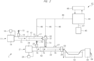
- FIG. 2 is an explanatory diagram illustrating a configuration example of a pellet manufacturing system (resin pellet manufacturing apparatus) 41 as a resin processing system using the resin processing apparatus 1 according to the present embodiment.
- the pellet manufacturing system 41 according to the present embodiment is a manufacturing system (manufacturing apparatus) for resin pellets, but can also function as a processing system (processing apparatus) for resin materials such as waste plastics.
- the pellet manufacturing system 41 illustrated in FIG. 2 further includes a cooling bath (strand bath) 42, a cutting apparatus 43, the heat exchanger 44, and a recovery container 45, in addition to the above-described resin processing apparatus 1.
- the operation of the pellet manufacturing system 41 including the resin processing apparatus 1 will be described with reference to FIG. 1 and FIG. 2 .
- the extruder 11 constituting the resin processing apparatus 1 is controlled by the control unit 18 and the extruder 21 constituting the resin processing apparatus 1 is controlled by the control unit 28, but the extruder 11 and the extruder 21 can also be controlled by a common control unit.
- the resin material 51 is supplied from the hopper 15 into the cylinder 12, and the resin material 52 is supplied from the hopper 25 into the cylinder 22.
- the resin material 51 supplied from the hopper 15 into the cylinder 12 contains a resin component and is, for example, crushed various used resin products, and waste plastics can be applied thereto.
- the resin material 51 supplied from the hopper 15 into the cylinder 12 may contain, in addition to the resin component, a filler other than the resin component (for example, an inorganic filler).
- a filler include glass fiber, carbon fiber, talc, and calcium carbonate.
- a thermal decomposition temperature T 1 of the resin material 51 will be referred to below, but the thermal decomposition temperature T 1 of the resin material 51 corresponds to the temperature at which the resin component contained in the resin material 51 supplied from the hopper 15 into the cylinder 12 thermally decomposes.
- the resin material 51 supplied from the hopper 15 into the cylinder 12 is plasticized into a molten resin while being conveyed forward in the cylinder 12 by the rotation of the screw 13.
- a kneading section (plasticizing section) 61 in the cylinder 12 of the extruder 11 is indicated by surrounding it by a dotted line.
- the kneading section 61 corresponds to a region where the resin material 51 supplied from the hopper 15 into the cylinder 12 is plasticized into a molten resin in the cylinder 12, and can be regarded as the plasticizing section.
- the kneading section 61 is located on the downstream side relative to the connection position of the hopper 15 and is located on the upstream side relative to the gas discharge unit 17.
- the resin material 51 in the cylinder 12 is not yet melted and is in a solid state on the upstream side relative to the kneading section 61, but the resin material 51 is plasticized in the kneading section 61 to be in a molten state (molten resin), and the resin material 51 in the cylinder 12 is a molten resin on the downstream side relative to the kneading section 61. Therefore, an arrow 71 in FIG. 2 indicates the flow of the resin material 51 in a solid state, and an arrow 72 in FIG. 2 indicates the flow of the resin material 51 in a molten state (molten resin).
- the resin material 51 supplied from the hopper 15 into the cylinder 12 contains a filler
- the molten resin in the cylinder 12 contains the filler.
- the temperature of the cylinder 12 of the extruder 11 on the downstream side relative to the kneading section 61 is set to be higher than the thermal decomposition temperature T 1 of the resin material 51.
- the temperature of the cylinder 12 on the downstream side relative to the kneading section 61 is set to a temperature (for example, 400°C) higher than the thermal decomposition temperature T 1 of the resin material 51.
- the temperature of the cylinder 12 of the extruder 11 can be controlled by the control unit 18 controlling the temperature adjustment mechanism of the cylinder 12.
- the "set temperature of the cylinder 12" means the "temperature of the cylinder 12 on the downstream side relative to the kneading section 61".
- the temperature of the cylinder 12 on the upstream side relative to the kneading section 61 can be set to an appropriate temperature as necessary, and may be equal to or lower than the thermal decomposition temperature T 1 of the resin material 51.
- the resin material 51 supplied from the hopper 15 into the cylinder 12 is plasticized in the kneading section 61 of the cylinder 12 to be a molten resin, and is sent further forward (downstream side) in the cylinder 12 by the rotation of the screw 13. Since the set temperature of the cylinder 12 is set to be higher than the thermal decomposition temperature T 1 of the resin material 51, the resin component in the molten resin in the cylinder 12 is heated to a temperature higher than the thermal decomposition temperature T 1 and is thermally decomposed on the downstream side relative to the kneading section 61, thereby becoming gasified (gaseous) monomer (hereinafter, referred to as "monomer gas").
- the monomer gas generated in the cylinder 12 is discharged from the gas discharge unit 17 of the cylinder 12 to the outside of the cylinder 12 and is sent to the heat exchanger 44 through the gas pipe (gas piping) 46.
- a part of the molten resin in the cylinder 12 is thermally decomposed into monomer gas and is sent from the gas discharge unit 17 through the gas pipe 46 to the heat exchanger 44, while the remainder (the molten resin that has not been thermally decomposed) is extruded from the tip of the cylinder 12. Further, the filler contained in the molten resin in the cylinder 12 is not thermally decomposed. Therefore, the filler contained in the molten resin in the cylinder 12 is extruded (discharged) from the tip of the cylinder 12 together with the molten resin that has not been thermally decomposed (monomerized).
- the residual resin (resin material containing filler) which is the material extruded from the tip of the cylinder 12 passes through the connection unit 31 and is supplied into the cylinder 22 from the opening of the cylinder 22 (opening for connection unit 31).
- An arrow 73 in FIG. 2 indicates the flow of the residual resin extruded from the tip of the cylinder 12.
- the residual resin (73) extruded from the tip of the cylinder 12 is supplied into the cylinder 22 through the connection unit 31.
- a part of the monomer gas that has flown from the cylinder 12 into the connection unit 31 is discharged to the outside of the connection unit 31 from a gas discharge unit (gas exhaust port, gas recovery mechanism) 32 provided on the connection unit 31 and is sent to the heat exchanger 44 through the gas pipe 46, and the remainder flows from the connection unit 31 into the cylinder 22 together with the molten resin and filler.
- a gas discharge unit gas exhaust port, gas recovery mechanism
- the resin material 52 supplied from the hopper 25 into the cylinder 22 is a resin material (raw material) for manufacturing resin pellets. Therefore, as the resin material 52 supplied from the hopper 25 into the cylinder 22, a resin material suitable for manufacturing resin pellets can be used.
- the resin component contained in this resin material 52 may be the same type of resin as the resin component contained in the resin material 51 supplied from the hopper 15 into the cylinder 12. In addition to the resin component, the resin material 52 may further contain a filler suitable for manufacturing resin pellets.
- a thermal decomposition temperature T 2 of the resin material 52 will be referred to below, but the thermal decomposition temperature T 2 of the resin material 52 corresponds to the temperature at which the resin component contained in the resin material 52 supplied from the hopper 25 into the cylinder 22 thermally decomposes.
- the resin material 52 supplied from the hopper 25 into the cylinder 22 is plasticized into a molten resin while being conveyed forward in the cylinder 22 by the rotation of the screw 23.
- a kneading section (plasticizing section) 62 in the cylinder 22 of the extruder 21 is indicated by surrounding it by a dotted line.
- the kneading section 62 corresponds to a region where the resin material 52 supplied from the hopper 25 into the cylinder 22 is plasticized in the cylinder 22 into a molten resin, and can be regarded as the plasticizing section.
- the kneading section 62 is located on the downstream side relative to the connection position of the hopper 25 and is located on the upstream side relative to the connection position of the connection unit 31.
- the resin material 52 in the cylinder 22 is not yet melted and is in a solid state on the upstream side relative to the kneading section 62, but the resin material 52 is plasticized in the kneading section 62 to be in a molten state (molten resin), and the resin material 52 in the cylinder 22 is a molten resin on the downstream side relative to the kneading section 62. Therefore, an arrow 74 in FIG. 2 indicates the flow of the resin material 52 in a solid state, and an arrow 75 in FIG. 2 indicates the flow of the resin material 52 in a molten state (molten resin).
- the resin material 52 supplied from the hopper 25 into the cylinder 22 is kneaded with the material (residual resin) supplied into the cylinder 22 from the tip of the cylinder 12 through the connection unit 31 by the screw 23 to form a kneaded resin mixture.
- the resin material 52 supplied from the hopper 25 into the cylinder 22 and the material (residual resin) supplied from the cylinder 12 through the connection unit 31 into the cylinder 22 are kneaded by the screw 23 in the cylinder 22 to form a kneaded resin mixture, and the formed kneaded resin mixture is conveyed in the cylinder 22 toward the tip side (downstream side) by the screw 23.
- the formed kneaded resin mixture is in a molten state (molten resin).
- An arrow 76 in FIG. 2 indicates the flow of this kneaded resin mixture.
- the molten resin on the upstream relative to the connection position of the connection unit 31 is composed of the resin component contained in the resin material 52, while the molten resin (kneaded resin mixture) on the downstream side relative to the connection position of the connection unit 31 is the kneaded mixture of the resin component contained in the resin material 51, the resin component contained in the resin material 52, and the filler contained in the resin material 51.
- the temperature of the cylinder 22 of the extruder 21 on the downstream side relative to the position where the residual resin (73) is supplied into the cylinder 22 (that is, the connection position of the connection unit 31) is set to be lower than the thermal decomposition temperature of the residual resin (73).
- the temperature of the cylinder 22 on the downstream side relative to the position where the residual resin (73) is supplied (that is, the connection position of the connection unit 31) is set to a temperature (for example, 100 to 300°C) lower than the thermal decomposition temperature of the residual resin (73).
- the temperature of the cylinder 22 of the extruder 21 can be controlled by the control unit 28 controlling the temperature adjustment mechanism of the cylinder 22.
- the “set temperature of the cylinder 22" means the “the temperature of the cylinder 22 on the downstream side relative to the position where the residual resin (73) extruded from the cylinder 12 of the extruder 11 is supplied into the cylinder 22 (that is, the connection position of the connection unit 31)".
- the temperature of the cylinder 22 on the upstream side relative to the position where the residual resin (73) is supplied can be set to an appropriate temperature as necessary.
- the thermal decomposition temperature of the residual resin (73) supplied from the extruder 11 into the cylinder 22 of the extruder 21 is substantially the same as the thermal decomposition temperature T 1 of the resin material 51.
- the set temperature of the cylinder 22 is set to a temperature lower than the thermal decomposition temperature of the residual resin (73), the residual resin (73) extruded from the cylinder 12 of the extruder 11 and supplied into the cylinder 22 of the extruder 21 is not heated to a temperature equal to or higher than the thermal decomposition temperature of the residual resin in the cylinder 22, and is thus hardly decomposed in the cylinder 22. Therefore, it is possible to suppress or prevent the monomer gas from being generated by the thermal decomposition of the molten resin (kneaded resin mixture) in the cylinder 22. Further, the filler contained in the molten resin is not thermally decomposed in the cylinder 22.
- the set temperature of the cylinder 22 is set to a temperature (for example, 100 to 300° C) that is lower than the thermal decomposition temperature of the residual resin and lower than the thermal decomposition temperature T 2 of the resin material 52.
- a temperature for example, 100 to 300° C
- the resin component in the molten resin (kneaded resin mixture) sent forward in the cylinder 12 by the rotation of the screw 13 is neither heated to a temperature equal to or higher than the thermal decomposition temperature of the residual resin (73) nor heated to a temperature equal to or higher than the thermal decomposition temperature T 2 of the resin material 52, and is thus hardly thermally decomposed. Therefore, it is possible to further suppress or prevent the monomer gas from being generated by the thermal decomposition of the molten resin (kneaded resin mixture) in the cylinder 22.
- the set temperature of the cylinder 22 of the extruder 2 is higher than the temperature at which the monomer gas generated in the cylinder 12 of the extruder 1 is liquefied.
- the set temperature of the cylinder 22 is set to a temperature (for example, 100 to 300°C) at which the monomer gas generated in the cylinder 12 and flowing from the cylinder 12 through the connection unit 31 into the cylinder 22 is not liquefied in the cylinder 22. In this way, it is possible to suppress or prevent the monomer gas generated in the cylinder 12 and flowing from the cylinder 12 through the connection unit 31 into the cylinder 22 from being liquefied in the cylinder 22.
- the monomer gas generated in the cylinder 12 and flowing from the cylinder 12 through the connection unit 31 into the cylinder 22 is discharged from the gas discharge unit 27 of the cylinder 22 to the outside of the cylinder 22 and is sent to the heat exchanger 44 through the gas pipe 46.
- the molten resin (kneaded resin mixture) sent forward in the cylinder 22 by the rotation of the screw 23 is extruded from the die 26 attached to the tip of the cylinder 22.
- the molten resin (kneaded resin mixture) is formed into a strand shape by the die 26 and is extruded from the die 26 as a strand (resin strand) 53.
- the strand 53 is the material extruded from the extruder 21 and is also the material that contains the residual resin supplied from the extruder 11 to the extruder 21.
- the strand 53 extruded from the die 26 is cooled and solidified (cured) in the cooling bath 42.
- the solidified strand 53 is cut to a predetermined length by the cutting apparatus 43.
- resin pellets 54 are manufactured.
- the resin processing apparatus 1 can function as a strand manufacturing apparatus.
- the resin material 51 supplied from the hopper 15 into the cylinder 12 contains a filler
- the residual resin (73) extruded from the tip of the cylinder 12 and supplied into the cylinder 22 through the connection unit 31 also contains the filler, and thus the strand 53 and the resin pellets 54 also contain the filler contained in the resin material 51.
- the resin material 52 supplied from the hopper 25 into the cylinder 22 contains a filler
- the strand 53 and the resin pellets 54 also contain the filler contained in the resin material 52.
- the monomer gas sent from the gas discharge units 17, 27, and 32 through the gas pipe 46 to the heat exchanger 44 is cooled and liquefied in the heat exchanger 44, thereby becoming a liquid monomer.
- the heat exchanger 44 can cool and liquefy the monomer gas by exchanging heat with cooling water 48.
- the liquid monomer produced in the heat exchanger 44 is sent to the recovery container 45 through a pipe (liquid piping) 47 and is stored in the recovery container 45.
- the liquid monomer stored in the recovery container 45 is taken out for reuse as required.
- the case of manufacturing the resin pellets 54 using the strand 53 extruded from the extruder 21 has been described as the method of processing a resin material.
- the case of letting the strand 53 extruded from the extruder 21 release the case of storing the strand 53 extruded from the extruder 21 in a container (not illustrated), and the like are also possible. In that case, the solidified strand 53 can be discarded later.
- FIG. 3 is an explanatory diagram illustrating a configuration of a processing system (processing apparatus) 101 of resin materials such as waste plastics studied by the inventor of the present invention.
- the processing system 101 illustrated in FIG. 3 includes an extruder 111, a heat exchanger 144, and a recovery container 145.
- the extruder 111 includes a cylinder 112, a screw disposed in the cylinder 112, a rotation drive mechanism 114 for rotating the screw in the cylinder 112, a hopper 115 arranged on the upstream side of the cylinder 112, and a gas discharge unit 117 that discharges gas produced in the cylinder 112 to the outside of the cylinder 112. Further, a tank (container) 118 for storing residue is attached to the tip of the cylinder 112 of the extruder 111.
- a resin material 151 is supplied from the hopper 115 into the cylinder 112.
- the resin material 151 supplied from the hopper 115 into the cylinder 112 is, for example, crushed various used resin products, and waste plastics can be applied thereto.
- the resin material 151 supplied from the hopper 115 into the cylinder 112 further contains a filler in addition to the resin component.
- the resin material 151 supplied from the hopper 115 into the cylinder 112 is melted into a molten resin while being sent forward in the cylinder 112 by the rotation of the screw.
- the temperature of the cylinder 112 is set to a temperature higher than the thermal decomposition temperature of the resin material 151.
- the molten resin in the cylinder 112 is thermally decomposed to generate monomer gas.
- the monomer gas generated in the cylinder 112 is discharged from the gas discharge unit 117 of the cylinder 112 to the outside of the cylinder 112 and is sent to the heat exchanger 144 through the gas pipe 146.
- a part of the molten resin in the cylinder 122 is thermally decomposed into monomer gas and is sent from the gas discharge unit 117 through the gas pipe 146 to the heat exchanger 144, while the remainder (the molten resin that has not been thermally decomposed) is extruded as a residual resin from the tip of the cylinder 112 and flows into the tank 118. Further, the filler contained in the molten resin in the cylinder 112 also flows into the tank 118 from the tip of the cylinder 112 together with the molten resin that has not been thermally decomposed.
- a part of the monomer gas generated in the cylinder 112 is sent from the gas discharge unit 117 through the gas pipe 146 to the heat exchanger 144, and the remainder flows into the tank 118 from the tip of the cylinder 112 together with the molten resin that has not been thermally decomposed.
- the monomer gas that has flown from the cylinder 112 into the tank 118 is discharged from a gas discharge unit 119 provided on the tank 118 to the outside of the tank 118, and is sent to the heat exchanger 144 through the gas pipe 146.
- the monomer gas sent from the gas discharge units 117 and 119 through the gas pipe 146 to the heat exchanger 144 is cooled and liquefied in the heat exchanger 144, thereby becoming a liquid monomer.
- the heat exchanger 144 can cool and liquefy the monomer gas by exchanging heat with cooling water 148.
- the liquid monomer produced in the heat exchanger 144 is sent to the recovery container 145 through a pipe 147 and is stored in the recovery container 145.
- the liquid monomer stored in the recovery container 145 is taken out for reuse as required.
- the stored amount the amount of residual resin that is extruded from the tip of the cylinder 112 and flows into the tank 118 and stored therein (hereinafter, referred to as the stored amount) gradually increases.
- the stored amount in the tank 118 increases, it is necessary to make the tank 118 empty before the tank 118 becomes full by removing the residual resin stored in the tank 118 from the tank 118.
- the monomer gas is a gas type that is undesirable for diffusing to the surroundings, it is necessary to prevent the monomer gas in the tank 118 from diffusing to the surroundings when removing the residual resin stored in the tank 118 from the tank 118, but this makes the work of removing the residual resin stored in the tank 118 difficult and increases the load for this work.
- the resin processing apparatus 1 includes the extruder 11 to which the resin material 51 is supplied and the extruder 21 to which the extruder 11 is connected and the residual resin (73) discharged from the extruder 11 is supplied. Specifically, the cylinder 12 of the extruder 11 is connected to the cylinder 22 of the extruder 21 such that the residual resin discharged (extruded) from the tip of the cylinder 12 of the extruder 11 is supplied into the cylinder 22 of the extruder 21. In the case of FIG.
- the cylinder 12 of the extruder 11 is connected to the cylinder 22 of the extruder 21 via the connection unit 31, and the residual resin (73) discharged (extruded) from the tip of the cylinder 12 is supplied into the cylinder 22 of the extruder 21 through the connection unit 31.
- One of the main features of the present embodiment is that the temperature of the cylinder of the extruder 11 on the downstream side relative to the kneading section 61 is set to be higher than the thermal decomposition temperature T 1 of the resin material 51, and the temperature of the cylinder 22 of the extruder 21 on the downstream side relative to the position where the residual resin (73) is supplied is set to be lower than the thermal decomposition temperature of the residual resin (73).
- the extruder 11 is used to thermally decompose the resin material 51, and the extruder 21 is used to process the residual resin (that is, the residue after thermal decomposition) discharged from the cylinder 12 of the extruder 11.
- the extruder 21 is used to manufacture resin pellets using the residual resin discharged from the cylinder 12 of the extruder 11.
- the resin material 51 is hardly decomposed in the cylinder 12, and thus almost no monomer gas is generated in the cylinder 12.
- the monomer gas is hardly discharged from the gas discharge unit 17 and the gas discharge unit 32 to the outside of the cylinder 12, and it is difficult to recover the liquefied monomer in the heat exchanger 44.
- the set temperature of the cylinder 12 (the set temperature of the cylinder 12 on the downstream side relative to the kneading section 61) is set to be higher than the thermal decomposition temperature T 1 of the resin material 51 such that the thermal decomposition of the resin material 51 is performed accurately in the cylinder 12.
- the resin component contained in the resin material 51 supplied from the hopper 15 into the cylinder 12 is heated to a temperature higher than the thermal decomposition temperature T 1 to be thermally decomposed, thereby generating the monomer gas, so that at least a part of the generated monomer gas can be discharged from the gas discharge unit 17 provided on the cylinder 12 and the gas discharge unit 32 provided on the connection unit 31.
- the monomer gas discharged from the gas discharge unit 17 and the gas discharge unit 32 can be liquefied in the heat exchanger 44.
- the monomer liquefied by the heat exchanger 44 can be stored in the recovery container 45 or the like for reuse.
- the set temperature of the cylinder 22 of the extruder 21 is set to a temperature lower than the thermal decomposition temperature of the residual resin (73) discharged from the extruder 11 and supplied to the cylinder 22 such that the residual resin is not thermally decomposed in the cylinder 22.
- the set temperature of the cylinder 22 of the extruder 21 is set to a temperature lower than the thermal decomposition temperature of the residual resin and lower than the thermal decomposition temperature T 2 of the resin material 52.
- the set temperature of the cylinder 22 is set to a temperature equal to or higher than the thermal decomposition temperature of the residual resin (73) supplied from the extruder 11 into the cylinder 22 and the set temperature of the cylinder 22 is set to a temperature equal to or higher than the thermal decomposition temperature T 2 of the resin material 52 unlike the present embodiment, monomer gas is generated by the thermal decomposition of the resin component in the cylinder 22, and thus the ratio of the resin component in the kneaded resin mixture formed in the cylinder 22 decreases by the amount of the generated monomer gas.
- the set temperature of the cylinder 22 of the extruder 21 is set to a temperature lower than the thermal decomposition temperature of the residual resin (73) supplied from the extruder 11 into the cylinder 22. It is more preferable that the set temperature of the cylinder 22 of the extruder 21 is set to a temperature lower than the thermal decomposition temperature of the residual resin (73) and lower than the thermal decomposition temperature T 2 of the resin material 52. In this way, it is possible to suppress or prevent the thermal decomposition of the resin component in the cylinder 22.
- the set temperature of the cylinder 22 by setting the set temperature of the cylinder 22 to be lower than the thermal decomposition temperature of the residual resin (73), it is possible to suppress or prevent the resin component contained in the residual resin (73) discharged from the extruder 11 and supplied into the cylinder 22 from being thermally decomposed in the cylinder 22. Further, by setting the set temperature of the cylinder 22 to a temperature lower than the thermal decomposition temperature T 2 of the resin material 52, it is possible to suppress or prevent the resin component contained in the resin material 52 supplied from the hopper 25 into the cylinder 22 from being thermally decomposed in the cylinder 22.
- the resin pellets 54 can be accurately formed. Therefore, the operation of the resin processing apparatus 1 is stabilized, and the resin pellets 54 can be manufactured stably.
- the resin material 52 supplied from the hopper 25 into the cylinder 22 and the residual resin (73) extruded from the cylinder 12 and supplied into the cylinder 22 are kneaded by the screw 23 to form the kneaded resin mixture, and the kneaded resin mixture is extruded from the die 26 connected to the tip of the cylinder 22.
- the residual resin (73) extruded from the cylinder 12 and supplied into the cylinder 22 has a fairly low resin component content.
- the resin material 51 is thermally decomposed in the cylinder 12 to generate monomer gas, and thus the resin component content in the residual resin (73) extruded from the cylinder 12 and supplied into the cylinder 22 is fairly lower than the resin component content in the resin material 51 at the stage when it is supplied from the hopper 15 into the cylinder 12. Therefore, when the resin material is not supplied from the hopper 25 into the cylinder 22 unlike the present embodiment, the residual resin (that is, material having a fairly low resin component content) extruded from the cylinder 12 and supplied into the cylinder 22 is conveyed by the screw 23 and is extruded from the die 26 connected to the tip of the cylinder 22. However, it is difficult to stably convey the material having a fairly low resin component content by the screw 23, and to stably extrude the material having a fairly low resin component content from the die 26.
- the resin material 52 is supplied from the hopper 25 into the cylinder 22.
- the resin material 52 supplied from the hopper 25 into the cylinder 22 and the residual resin (73) extruded from the cylinder 12 and supplied into the cylinder 22 are kneaded by the screw 23 in the cylinder 22 to form the kneaded resin mixture. Therefore, even when the resin component content in the residual resin (73) supplied from the cylinder 12 into the cylinder 22 is fairly low, the resin component content in the kneaded resin mixture formed in the cylinder 22 can be made higher than the resin component content in the residual resin (73) supplied from the cylinder 12 into the cylinder 22.
- the kneaded resin mixture formed in the cylinder 22 can be stably conveyed by the screw 23 and can also be stably extruded from the die 26 connected to the tip of the cylinder 22. Therefore, the operation of the resin processing apparatus 1 is stabilized, and the resin pellets 54 can be manufactured stably.
- the extruder 11 having the cylinder 12 is used to thermally decompose the resin material 51
- the extruder 21 having the cylinder 22 is used to manufacture resin pellets using the residual resin extruded from the cylinder 12 of the extruder 11.
- the resin material 52 is supplied from the hopper 25 into the cylinder 22 of the extruder 21 such that resin pellets can be manufactured using the residual resin supplied from the cylinder 12 of the extruder 11 into the cylinder 22 of the extruder 21.
- the resin material 52 supplied from the hopper 25 into the cylinder 22 and the residual resin supplied from the cylinder 12 into the cylinder 22 are kneaded to form a kneaded resin mixture, and the kneaded resin mixture can be stably extruded from the die 26 connected to the tip of the cylinder 22.
- the residual resin extruded from the tip of the cylinder 12 is supplied into the cylinder 22 to which the cylinder 12 is connected. Then, the residual resin supplied from the cylinder 12 into the cylinder 22 and the resin material 52 supplied from the hopper 25 into the cylinder 22 are kneaded by the screw 23 to form a kneaded resin mixture, and the resin pellets 54 are manufactured by cutting the kneaded resin mixture extruded from the die 26 connected to the tip of the cylinder 22. Therefore, there is no need to perform the work of emptying the tank 118 by removing the material stored in the tank 118 from the tank 118, which is necessary in the case of the processing system 101 according to the studied example above.
- the resin processing apparatus 1 can be operated continuously for a long period of time, the operating efficiency of the resin processing apparatus 1 and the pellet manufacturing system 41 including the same can be improved. Moreover, the processing efficiency of the resin material 51 can be improved. When a waste plastic is used as the resin material 51, the processing efficiency of the waste plastic can be improved, and the cost of processing the waste plastic can be reduced. Therefore, resin materials such as waste plastics can be efficiently processed for recycling. In addition, since the residual resin extruded from the tip of the cylinder 12 is supplied into the cylinder 22 to which the cylinder 12 is connected, it becomes easier to prevent the monomer gas generated in the cylinder 12 from diffusing to the surroundings.
- the kneading section 61 is located on the downstream side relative to the connection position of the hopper 15 and on the upstream side relative to the gas discharge unit 17. In the case where there is no gas discharge unit 17 as illustrated in FIG. 1 described later, the kneading section 61 is located on the downstream side relative to the tip of the cylinder 12. In the kneading section 61 of the cylinder 12, the molten resin formed by plasticizing the resin material 51 fills the conveyance space in the cylinder 12 (the space in which the resin material is conveyed by the screw 13).
- the monomer gas generated by the thermal decomposition of the molten resin in the cylinder 12 cannot return to the upstream side relative to the kneading section 61 by passing through the kneading section 61 in the cylinder 12, and it is thus possible to prevent the monomer gas from being discharged to the outside from the hopper 15.
- the monomer gas generated by the thermal decomposition of the molten resin in the cylinder 12 is discharged from the gas discharge unit 17 and the gas discharge unit 32, or is supplied into the cylinder 22 from the tip of the cylinder 12 through the connection unit 31.
- the kneading section 62 is located on the downstream side relative to the connection position of the hopper 25 and on the upstream side relative to the connection position of the connection unit 31.
- the molten resin formed by plasticizing the resin material 52 fills the conveyance space in the cylinder 22 (the space in which the resin material is conveyed by the screw 23). Therefore, the monomer gas supplied from the tip of the cylinder 12 through the connection unit 31 into the cylinder 22 cannot return to the upstream side relative to the kneading section 62 by passing through the kneading section 62 in the cylinder 22.
- the kneaded resin mixture (molten resin) formed in the cylinder 22 is extruded from a hole (resin discharge port) of the die 26, and the hole of the die 26 and the resin flow path in front of the hole are filled with the kneaded resin mixture (molten resin). Therefore, the monomer gas supplied into the cylinder 22 through the connection unit 31 from the tip of the cylinder 12 cannot pass through the hole of the die 26 and the resin flow path, and thus is not discharged to the outside through the hole of the die 26.
- the monomer gas supplied into the cylinder 22 from the tip of the cylinder 12 through the connection unit 31 is discharged to the outside of the cylinder 22 from the gas discharge unit 27, so that it is possible to prevent the monomer gas from being discharged to the outside from the hopper 25 and the die 26.
- the whole amount of monomer gas generated by the thermal decomposition of the resin material 51 in the cylinder 12 can be sent from the gas discharge units 17, 27, and 32 through the gas pipe 46 to the heat exchanger 44 and liquefied, and can be stored and recovered in the recovery container 45. Therefore, it is possible to prevent the monomer gas generated by the thermal decomposition in the cylinder 12 from diffusing to the surroundings. Further, even if monomer gas is generated by the thermal decomposition in the cylinder 22, the whole amount of the monomer gas can be sent from the gas discharge unit 27 through the gas pipe 46 to the heat exchanger 44 and liquefied, and can be stored and recovered in the recovery container 45. Therefore, even if monomer gas is generated by the thermal decomposition in the cylinder 22, it is possible to prevent the monomer gas from diffusing to the surroundings.
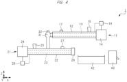
- FIG. 4 is an explanatory diagram (side view) illustrating a first modification of the resin processing apparatus 1 according to the present embodiment.
- FIG. 5 is an explanatory diagram (plan view) illustrating a second modification of the resin processing apparatus 1 according to the present embodiment.
- illustrations of the control units 18 and 28 are omitted in FIG. 4
- illustrations of the screws 13 and 23 in the cylinders 12 and 22 and the control units 18 and 28 are omitted in FIG. 5 .
- the cooling bath 42 and the cutting apparatus 43 are also illustrated in FIG. 4 and FIG. 5 .
- FIG. 1 , FIG. 4 , and FIG. 5 and FIG. 6 and FIG. 7 described later two directions out of the X direction, the Y direction, and the Z direction are illustrated, and the X direction, the Y direction, and the Z direction are directions that are perpendicular to each other.
- the X and Y directions are horizontal directions
- the Z direction is a height direction.
- the long axis direction of the cylinder 12 and the long axis direction of the cylinder 22 are the same, and are the X direction here.
- the conveying direction of the resin material in the cylinder 12 and the conveying direction of the resin material in the cylinder 22 are the same in the case of FIG. 1
- the conveying direction of the resin material in the cylinder 12 and the conveying direction of the resin material in the cylinder 22 are opposite to each other in the case of FIG. 4 (first modification).
- the direction from the upstream side to the downstream side of the cylinder 12 and the direction from the upstream side to the downstream side of the cylinder 22 are the same. Specifically, in the case of FIG. 1 , the resin material is conveyed from the left side of the drawing to the right side of the drawing in both the cylinder 12 and the cylinder 22.
- the direction from the upstream side to the downstream side of the cylinder 12 and the direction from the upstream side to the downstream side of the cylinder 22 are opposite to each other.
- the resin material is conveyed from the right side of the drawing to the left side of the drawing in the cylinder 12, and the resin material is conveyed from the left side of the drawing to the right side of the drawing in the cylinder 22.
- the long axis direction of the cylinder 12 and the long axis direction of the cylinder 22 are directions that intersect with each other, for example, directions that are perpendicular to each other, and the long axis direction of the cylinder 12 is the Y direction and the long axis direction of the cylinder 22 is the X direction here.
- the long axis direction of the cylinder 12 refers to the long side direction or longitudinal direction of the cylinder 12, and the cylindrical cylinder 12 extends in the long axis direction of the cylinder 12.
- the long axis direction of the cylinder 12 and the long axis direction of the screw 13 in the cylinder 12 are the same, and the long axis direction of the screw 13 corresponds to the axial direction of a rotating shaft of the screw 13.
- the resin material is conveyed in the long axis direction from the upstream side to the downstream side by the rotating screw 13.
- the long axis direction of the cylinder 22 refers to the long side direction or longitudinal direction of the cylinder 22, and the cylindrical cylinder 22 extends in the long axis direction of the cylinder 22.
- the long axis direction of the cylinder 22 and the long axis direction of the screw 23 in the cylinder 22 are the same, and the long axis direction of the screw 23 corresponds to the axial direction of a rotating shaft of the screw 23.
- the resin material is conveyed in the long axis direction from the upstream side to the downstream side by the rotating screw 23.
- the dimension of the entire resin processing apparatus 1 in the Y direction can be reduced as compared with the case of FIG. 5 (second modification). Therefore, in the case of FIG. 1 , the dimension of the planar area required to install the resin processing apparatus 1, the cooling bath 42, and the cutting apparatus 43 in the Y direction can be reduced as compared with the case of FIG. 5 (second modification).
- the dimension of the entire resin processing apparatus 1 in the Y direction can be reduced as compared with the case of FIG. 5 (second modification).
- the dimension of the entire resin processing apparatus 1 in the X direction can be reduced as compared with the case of FIG. 1 above. Therefore, in the case of FIG. 4 (first modification), the dimension of the planar area required to install the resin processing apparatus 1, the cooling bath 42, and the cutting apparatus 43 in the Y direction can be reduced as compared with the case of FIG. 5 (second modification), and the dimension of the planar area required to install the resin processing apparatus 1, the cooling bath 42, and the cutting apparatus 43 in the X direction can be reduced as compared with the case of FIG. 1 above.
- the long axis direction of the cylinder 12 and the long axis direction of the cylinder 22 are directions that intersect with each other, and preferably are perpendicular to each other, and the long axis direction of the cylinder 12 is the Y direction and the long axis direction of the cylinder 22 is the X direction here.
- the height position of the cylinder 12 is approximately the same as the height position of the cylinder 22, and the tip of the cylinder 12 faces the side surface of the cylinder 22 and is connected to the side surface.
- the cylinder 22 has an opening (opening for the cylinder 12) at the position where the cylinder 12 is connected, and the cylinder 12 is connected so as to communicate with the opening. In this way, the material extruded from the tip of the cylinder 12 is supplied into the cylinder 22 through the opening of the cylinder 22 (opening for the cylinder 12).
- the length (length in the long axis direction) of the cylinder 12 is longer than the length (length in the long axis direction) of the cylinder 22. It is desirable to sufficiently thermally decompose the resin material 51 in the cylinder 12 to increase the amount of generated monomer gas, and it is desirable for this purpose that the length of the cylinder 12 is long to some extent.
- the length of the cylinder 12 does not need to be very long. Accordingly, the amount of monomer gas generated in the cylinder 12 can be increased by increasing the length of the cylinder 12, and the overall dimensions of the resin processing apparatus 1 can be reduced by making the length of the cylinder 22 shorter than the length of the cylinder 12.
- FIG. 8 is an explanatory diagram illustrating a fourth modification of the resin processing apparatus 1 according to the present embodiment and the pellet manufacturing system 41 using the same.
- FIG. 9 is an explanatory diagram illustrating a fifth modification of the resin processing apparatus 1 according to the present embodiment and the pellet manufacturing system 41 using the same.
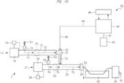
- FIG. 10 is an explanatory diagram illustrating a sixth modification of the resin processing apparatus 1 according to the present embodiment and the pellet manufacturing system 41 using the same.
- FIG. 8 to FIG. 10 each correspond to FIG. 2 above.
- the gas discharge unit 27 is not provided on the cylinder 22 of the extruder 21, and thus the gas pipe 46 connected to the gas discharge unit 27 is not provided either.
- the gas discharge unit 27 is not provided on the cylinder 22 of the extruder 21 and the gas discharge unit 32 is not provided on the connection unit 31, and thus the gas pipe 46 connected to the gas discharge unit 27 and the gas pipe 46 connected to the gas discharge unit 32 are not provided either.
- FIG. 8 fourth modification
- FIG. 9 the gas discharge unit 27 is not provided on the cylinder 22 of the extruder 21 and the gas discharge unit 32 is not provided on the connection unit 31, and thus the gas pipe 46 connected to the gas discharge unit 27 and the gas pipe 46 connected to the gas discharge unit 32 are not provided either.
- the gas discharge unit 27 is not provided on the cylinder 22 of the extruder 21 and the gas discharge unit 17 is not provided on the cylinder 12 of the extruder 11, and thus the gas pipe 46 connected to the gas discharge unit 17 and the gas pipe 46 connected to the gas discharge unit 27 are not provided either.
- the case of FIG. 8 (fourth modification), the case of FIG. 9 (fifth modification), and the case of FIG. 10 (sixth modification) have the same configurations as those of the resin processing apparatus 1 in FIG. 2 and the pellet manufacturing system 41 using the same described above.
- FIG. 2 When the cases of FIG. 2 , FIG. 8 (fourth modification), FIG. 9 (fifth modification), and FIG. 10 (sixth modification) are compared, it is the case of FIG. 2 that can most easily increase the recovery efficiency of the monomer gas generated in the resin processing apparatus 1.
- monomer gas generated in the resin processing apparatus 1 can be recovered from the gas discharge unit 17 provided on the cylinder 12 of the extruder 11, the gas discharge unit 32 provided on the connection unit 31, and the gas discharge unit 27 provided on the cylinder 22 of the extruder 21.
- the recovery efficiency of the monomer gas generated in the resin processing apparatus 1 can be more easily increased in the case of FIG. 8 (fourth modification) as compared with the cases of FIG. 9 (fifth modification) and FIG. 10 (sixth modification). This is because the monomer gas generated in the resin processing apparatus 1 can be recovered from both the gas discharge unit 17 provided on the cylinder 12 of the extruder 11 and the gas discharge unit 32 provided on the connection unit 31 in the case of FIG. 8 (fourth modification). Further, in the case of FIG.
- the monomer gas generated in the resin processing apparatus 1 can be recovered from the gas discharge unit 17 provided on the cylinder 12 of the extruder 11. Further, in the case of FIG. 10 (sixth modification), the monomer gas generated in the resin processing apparatus 1 can be recovered from the gas discharge unit 32 provided on the connection unit 31.
- the configuration of the resin processing apparatus 1 and the pellet manufacturing system 41 using the same can be further simplified as compared with the case of FIG. 8 (fourth modification).
Landscapes
- Engineering & Computer Science (AREA)
- Mechanical Engineering (AREA)
- Thermal Sciences (AREA)
- Physics & Mathematics (AREA)
- Chemical & Material Sciences (AREA)
- Chemical Kinetics & Catalysis (AREA)
- Health & Medical Sciences (AREA)
- Sustainable Development (AREA)
- Life Sciences & Earth Sciences (AREA)
- Medicinal Chemistry (AREA)
- Polymers & Plastics (AREA)
- Organic Chemistry (AREA)
- Environmental & Geological Engineering (AREA)
- Processing And Handling Of Plastics And Other Materials For Molding In General (AREA)
- Separation, Recovery Or Treatment Of Waste Materials Containing Plastics (AREA)
- Extrusion Moulding Of Plastics Or The Like (AREA)
Abstract
A resin processing device 1 comprises: an extruder 11 to which a resin material 51 is fed; and an extruder 21 which is connected to the extruder 11 and to which residual resin discharged from the extruder 11 is fed. The temperature of a cylinder 12 for the extruder 1 is set such that the temperature on the downstream side relative to a kneading section 61 is higher than the pyrolytic temperature of the resin material 51. The temperature of a cylinder 22 for the extruder 12 is set such that the temperature on the downstream side relative to a position where the residual resin is fed is higher than the pyrolytic temperature of the residual resin.
Description
- The present invention relates to a resin processing apparatus, a method of manufacturing resin pellets, and a method of processing a resin material.
-
Japanese Unexamined Patent Application Publication No. H11-106758 Japanese Unexamined Patent Application Publication No. H11-50072 -
- Patent Document 1:
Japanese Unexamined Patent Application Publication No. H11-106758 - Patent Document 2:
Japanese Unexamined Patent Application Publication No. H11-50072 - Processing resin materials such as waste plastics for recycling has been promoted in recent years, and it is thus desirable to process the resin materials efficiently.
- One possible method for processing resin materials such as waste plastics is to thermally decompose the resin materials to generate monomer and then recover the generated monomer. An extruder can be used for the thermal decomposition of the resin materials. For example, a resin material to be processed is supplied into a cylinder of an extruder, and the resin material is melted while being conveyed forward by a screw in the cylinder, and the molten resin is thermally decomposed in the cylinder of the extruder to generate monomer gas. The monomer gas generated in the cylinder of the extruder is liquefied by sending it to a heat exchanger from a gas discharge unit of the cylinder, and the liquefied monomer can be recovered.
- In this case, the residue after the processing of the resin material is extruded from the tip of the cylinder of the extruder. When the resin material to be processed contains a filler, the filler is also contained in the residue extruded from the tip of the cylinder of the extruder. In order to deal with the residue extruded from the tip of the cylinder, it is conceivable to connect a storage container to the tip of the cylinder of the extruder and store the residue extruded from the tip of the cylinder of the extruder in the storage container. However, when the storage container becomes full, it becomes impossible to continue the processing of the resin material using the extruder. For this reason, it is necessary to make the storage container connected to the tip of the cylinder empty before the container becomes full by removing the residue stored in the storage container. During this work, the operation of the extruder must be stopped, which reduces the operating efficiency of the extruder and reduces the processing efficiency of resin materials such as waste plastics. Also, the necessity for this work may increase the cost of processing resin materials such as waste plastics. Further, since it is desirable to prevent the monomer gas in the storage container from diffusing to the surroundings when removing the residue from the storage container, the work of removing the residue from the storage container is difficult and heavy in workload.
- Other problems and novel features will be apparent from the description of this specification and accompanying drawings.
- According to one embodiment, a resin processing apparatus includes a first extruder to which a first resin material is supplied and a second extruder to which the first extruder is connected and a residual resin discharged from the first extruder is supplied. A temperature of a cylinder of the first extruder on a downstream side relative to a first kneading section is set to be higher than a thermal decomposition temperature of the first resin material. A temperature of a cylinder of the second extruder on a downstream side relative to a position where the residual resin is supplied is set to be lower than a thermal decomposition temperature of the residual resin.
- According to one embodiment, it is possible to process resin materials such as waste plastics efficiently.
-
- [
FIG. 1 ] is an explanatory diagram illustrating a schematic configuration of a resin processing apparatus according to an embodiment. - [
FIG. 2 ] is an explanatory diagram illustrating a configuration example of a pellet manufacturing system using the resin processing apparatus according to the embodiment. - [
FIG. 3 ] is an explanatory diagram illustrating a configuration of a processing system of waste plastics studied by the inventor of the present invention. - [
FIG. 4 ] is an explanatory diagram illustrating a resin processing apparatus according to a first modification. - [
FIG. 5 ] is an explanatory diagram illustrating a resin processing apparatus according to a second modification. - [
FIG. 6 ] is an explanatory diagram illustrating a resin processing apparatus according to a third modification. - [
FIG. 7 ] is an explanatory diagram illustrating the resin processing apparatus according to the third modification. - [
FIG. 8 ] is an explanatory diagram illustrating a resin processing apparatus according to a fourth modification. - [
FIG. 9 ] is an explanatory diagram illustrating a resin processing apparatus according to a fifth modification. - [
FIG. 10 ] is an explanatory diagram illustrating a resin processing apparatus according to a sixth modification. - Hereinafter, an embodiment will be described in detail with reference to drawings. Note that the members having the same function are denoted by the same reference characters throughout the drawings for describing the embodiment, and the repetitive description thereof will be omitted. Further, in the following embodiment, the description of the same or similar part will not be repeated in principle unless particularly required.
- An overall configuration of a
resin processing apparatus 1 according to the present embodiment will be described with reference toFIG. 1. FIG. 1 is an explanatory diagram (side view) illustrating a schematic configuration of theresin processing apparatus 1 according to the present embodiment. - The
resin processing apparatus 1 illustrated inFIG. 1 includes anextruder 11 and anextruder 21, and has a configuration in which theseextruders - The
extruder 11 includes a cylinder (barrel) 12, ascrew 13 rotatably arranged in thecylinder 12, arotation drive mechanism 14 for rotating thescrew 13 in thecylinder 12, a hopper (material feeder, material supply unit) 15 arranged on an upstream side (back end side) of thecylinder 12, and acontrol unit 18 for controlling the operation of theextruder 11. Theextruder 21 includes a cylinder (barrel) 22, ascrew 23 rotatably arranged in thecylinder 22, arotation drive mechanism 24 for rotating thescrew 23 in thecylinder 22, a hopper (material feeder, material supply unit) 25 arranged on an upstream side (back end side) of thecylinder 22, a die (metal mold) 26 attached to a tip of thecylinder 22 on a downstream side, and acontrol unit 28 for controlling the operation of theextruder 21. Thecylinder 12 is made up of a plurality of cylinder blocks, which are arranged and connected in a direction from the upstream side to the downstream side. Thecylinder 22 is made up of a plurality of cylinder blocks, which are arranged and connected in a direction from the upstream side to the downstream side. No molding die (corresponding to the die 26) is attached to the tip of thecylinder 12. In addition, theresin processing apparatus 1 illustrated inFIG. 1 further includes aconnection unit 31 for connecting thecylinder 12 of theextruder 11 and thecylinder 22 of theextruder 21 to supply the material extruded from thecylinder 12 of theextruder 11 into thecylinder 22 of theextruder 21. - The
hopper 15 is connected to an upper surface of thecylinder 12, so that aresin material 51 to be processed (such as waste plastic) can be supplied into thecylinder 12 through thehopper 15. Examples of the waste plastic include plastic products discarded after being used in general households or the like and plastic waste (parts that cannot be used as products) generated during the manufacturing process of plastic products. - The
cylinder 12 has a temperature adjustment mechanism (temperature control means) such as a heater (not illustrated). Thecontrol unit 18 controls the temperature adjustment mechanism of thecylinder 12, whereby the temperature of thecylinder 12 can be controlled. Thehopper 25 is connected to an upper surface of thecylinder 22, so that aresin material 52 can be supplied into thecylinder 22 through thehopper 25. Thecylinder 22 has a temperature adjustment mechanism (temperature control means) such as a heater (not illustrated). Thecontrol unit 28 controls the temperature adjustment mechanism of thecylinder 22, whereby the temperature of thecylinder 22 can be controlled. - Note that, when referring to the "downstream side" and the "upstream side" with respect to the
cylinder 12 and thescrew 13, the "downstream side" means the downstream side of the flow of the material (resin) in thecylinder 12, and the "upstream side" means the upstream side of the flow of the material (resin) in thecylinder 12. Therefore, in thecylinder 12 and thescrew 13, the side closer to the tip of thecylinder 12 is the downstream side, and the side farther from the tip of the cylinder 12 (that is, the side closer to the hopper 15) is the upstream side. Note that the tip of thecylinder 12 corresponds to the end of thecylinder 12 from which the resin is extruded, and thus corresponds to the end connected to theconnection unit 31. - In addition, when referring to the "downstream side" and the "upstream side" with respect to the
cylinder 22 and thescrew 23, the "downstream side" means the downstream side of the flow of the material (resin) in thecylinder 22, and the "upstream side" means the upstream side of the flow of the material (resin) in thecylinder 22. Therefore, in thecylinder 22 and thescrew 23, the side closer to the tip of thecylinder 22 is the downstream side, and the side farther from the tip of the cylinder 22 (that is, the side closer to the hopper 25) is the upstream side. Note that the tip of thecylinder 22 corresponds to the end of thecylinder 22 from which the resin is extruded, and thus corresponds to the end to which thedie 26 is connected. - Two
screws 13 are rotatably inserted and disposed inside thecylinder 12. Also, twoscrews 23 are rotatably inserted and disposed inside thecylinder 22. Therefore, each of theextruders screws 13 are arranged to mesh with each other and rotate in thecylinder 12, and the twoscrews 23 are arranged to mesh with each other and rotate in thecylinder 22. In thecylinder 12, the resin material is conveyed and kneaded by the rotating screws 13. Further, in thecylinder 22, the resin material is conveyed and kneaded by the rotating screws 23. - In the present embodiment, the case where the number of
screws 13 in thecylinder 12 is two is described, but as another aspect, the number ofscrews 13 in thecylinder 12 may be one. Further, in the present embodiment, the case where the number ofscrews 23 in thecylinder 22 is two is described, but as another aspect, the number ofscrews 23 in thecylinder 22 may be one. - The
cylinder 12 has an opening at a position where thehopper 15 is connected, and thehopper 15 is connected so as to communicate with the opening. In this way, theresin material 51 put into thehopper 15 is supplied into thecylinder 12 through the opening of thecylinder 12. - The
cylinder 12 has a gas discharge unit (gas exhaust port, gas recovery mechanism) 17 that discharges gas produced (generated) in thecylinder 12 to the outside of thecylinder 12. In thecylinder 12, thegas discharge unit 17 is located on the downstream side relative to the connection position of thehopper 15. The gas generated in thecylinder 12 is discharged (exhausted) from thegas discharge unit 17 to the outside of thecylinder 12 and is sent to aheat exchanger 44 described later through agas pipe 46 described later. - The
cylinder 22 has an opening (hopper opening) at a position where thehopper 25 is connected, and thehopper 25 is connected so as to communicate with the hopper opening. In this way, theresin material 52 put into thehopper 25 is supplied into thecylinder 22 through the hopper opening of thecylinder 22. - The
extruder 11 is connected to theextruder 21 such that a residual resin discharged from theextruder 11 is supplied to theextruder 21. Specifically, thecylinder 12 of theextruder 11 is connected to thecylinder 22 of theextruder 21 via theconnection unit 31. The tip of thecylinder 12 is connected to theconnection unit 31, and an opening of the tip of thecylinder 12 communicates with theconnection unit 31. Theconnection unit 31 has a passageway (cavity) through which the material (residual resin) discharged from the tip of thecylinder 12 can pass. Thecylinder 22 has an opening (opening for the connection unit 31) at the position where theconnection unit 31 is connected, and theconnection unit 31 is connected so as to communicate with the opening. In this way, the material (residual resin) discharged from theextruder 11, that is, the material (residual resin) discharged from the tip of thecylinder 12 passes through the inside of theconnection unit 31 and is supplied into thecylinder 22 through the opening (opening for the connection unit 31) of thecylinder 22. Theconnection unit 31 can function as a path through which the material (residual resin) discharged from the tip of thecylinder 12 reaches (is supplied to) the inside of thecylinder 22. In thecylinder 22, the connection position of theconnection unit 31 is located on the downstream side relative to the connection position of thehopper 25. Further, in the case ofFIG. 1 , the height position of thecylinder 12 is higher than the height position of thecylinder 22, theconnection unit 31 is connected to the upper surface side ofcylinder 22, and the material (residual resin) extruded from the tip ofcylinder 12 is supplied into thecylinder 22 from the upper surface side of thecylinder 22 through theconnection unit 31. - The
cylinder 22 of theextruder 21 has a gas discharge unit (gas exhaust port, gas recovery mechanism) 27 that discharges gas that has flown into thecylinder 22 from thecylinder 12 to the outside of thecylinder 22. In thecylinder 22, thegas discharge unit 27 is located on the downstream side relative to the connection position of thehopper 25 and located on the downstream side relative to the connection position of theconnection unit 31. The gas that has flown into thecylinder 22 from thecylinder 12 through theconnection unit 31 is discharged (exhausted) from thegas discharge unit 27 to the outside of thecylinder 22 and is sent to theheat exchanger 44 described later through thegas pipe 46 described later. - The die 26 can function to shape the kneaded resin mixture (molten resin) extruded from the
cylinder 22 into a predetermined cross-sectional shape (for example, strand shape) and discharge it. Therefore, thedie 26 is a die (die, metal mold) for extrusion molding. Since the kneaded resin mixture extruded from the tip of thecylinder 22 needs to be molded into a predetermined shape (here, strand shape), thedie 26 for resin molding is attached to the tip of thecylinder 22. However, since it is sufficient that the material extruded from the tip of thecylinder 12 can be supplied into thecylinder 22 through theconnection unit 31, no die (metal mold) for resin molding is attached to the tip of thecylinder 12. -
FIG. 2 is an explanatory diagram illustrating a configuration example of a pellet manufacturing system (resin pellet manufacturing apparatus) 41 as a resin processing system using theresin processing apparatus 1 according to the present embodiment. Thepellet manufacturing system 41 according to the present embodiment is a manufacturing system (manufacturing apparatus) for resin pellets, but can also function as a processing system (processing apparatus) for resin materials such as waste plastics. - The
pellet manufacturing system 41 illustrated inFIG. 2 further includes a cooling bath (strand bath) 42, a cuttingapparatus 43, theheat exchanger 44, and arecovery container 45, in addition to the above-describedresin processing apparatus 1. - Next, the operation of the
pellet manufacturing system 41 including theresin processing apparatus 1 will be described with reference toFIG. 1 andFIG. 2 . Note that theextruder 11 constituting theresin processing apparatus 1 is controlled by thecontrol unit 18 and theextruder 21 constituting theresin processing apparatus 1 is controlled by thecontrol unit 28, but theextruder 11 and theextruder 21 can also be controlled by a common control unit. - The
resin material 51 is supplied from thehopper 15 into thecylinder 12, and theresin material 52 is supplied from thehopper 25 into thecylinder 22. - The
resin material 51 supplied from thehopper 15 into thecylinder 12 contains a resin component and is, for example, crushed various used resin products, and waste plastics can be applied thereto. Theresin material 51 supplied from thehopper 15 into thecylinder 12 may contain, in addition to the resin component, a filler other than the resin component (for example, an inorganic filler). Examples of the filler include glass fiber, carbon fiber, talc, and calcium carbonate. - In addition, a thermal decomposition temperature T1 of the
resin material 51 will be referred to below, but the thermal decomposition temperature T1 of theresin material 51 corresponds to the temperature at which the resin component contained in theresin material 51 supplied from thehopper 15 into thecylinder 12 thermally decomposes. - In the
extruder 11, theresin material 51 supplied from thehopper 15 into thecylinder 12 is plasticized into a molten resin while being conveyed forward in thecylinder 12 by the rotation of thescrew 13. InFIG. 1 andFIG. 2 , a kneading section (plasticizing section) 61 in thecylinder 12 of theextruder 11 is indicated by surrounding it by a dotted line. The kneadingsection 61 corresponds to a region where theresin material 51 supplied from thehopper 15 into thecylinder 12 is plasticized into a molten resin in thecylinder 12, and can be regarded as the plasticizing section. In thecylinder 12 of theextruder 11, the kneadingsection 61 is located on the downstream side relative to the connection position of thehopper 15 and is located on the upstream side relative to thegas discharge unit 17. - In the
cylinder 12, theresin material 51 in thecylinder 12 is not yet melted and is in a solid state on the upstream side relative to thekneading section 61, but theresin material 51 is plasticized in thekneading section 61 to be in a molten state (molten resin), and theresin material 51 in thecylinder 12 is a molten resin on the downstream side relative to thekneading section 61. Therefore, anarrow 71 inFIG. 2 indicates the flow of theresin material 51 in a solid state, and anarrow 72 inFIG. 2 indicates the flow of theresin material 51 in a molten state (molten resin). When theresin material 51 supplied from thehopper 15 into thecylinder 12 contains a filler, the molten resin in thecylinder 12 contains the filler. - The temperature of the
cylinder 12 of theextruder 11 on the downstream side relative to thekneading section 61 is set to be higher than the thermal decomposition temperature T1 of theresin material 51. Specifically, the temperature of thecylinder 12 on the downstream side relative to thekneading section 61 is set to a temperature (for example, 400°C) higher than the thermal decomposition temperature T1 of theresin material 51. The temperature of thecylinder 12 of theextruder 11 can be controlled by thecontrol unit 18 controlling the temperature adjustment mechanism of thecylinder 12. When the "set temperature of thecylinder 12" is mentioned in the following description, it means the "temperature of thecylinder 12 on the downstream side relative to thekneading section 61". The temperature of thecylinder 12 on the upstream side relative to thekneading section 61 can be set to an appropriate temperature as necessary, and may be equal to or lower than the thermal decomposition temperature T1 of theresin material 51. - The
resin material 51 supplied from thehopper 15 into thecylinder 12 is plasticized in thekneading section 61 of thecylinder 12 to be a molten resin, and is sent further forward (downstream side) in thecylinder 12 by the rotation of thescrew 13. Since the set temperature of thecylinder 12 is set to be higher than the thermal decomposition temperature T1 of theresin material 51, the resin component in the molten resin in thecylinder 12 is heated to a temperature higher than the thermal decomposition temperature T1 and is thermally decomposed on the downstream side relative to thekneading section 61, thereby becoming gasified (gaseous) monomer (hereinafter, referred to as "monomer gas"). The monomer gas generated in thecylinder 12 is discharged from thegas discharge unit 17 of thecylinder 12 to the outside of thecylinder 12 and is sent to theheat exchanger 44 through the gas pipe (gas piping) 46. - A part of the molten resin in the
cylinder 12 is thermally decomposed into monomer gas and is sent from thegas discharge unit 17 through thegas pipe 46 to theheat exchanger 44, while the remainder (the molten resin that has not been thermally decomposed) is extruded from the tip of thecylinder 12. Further, the filler contained in the molten resin in thecylinder 12 is not thermally decomposed. Therefore, the filler contained in the molten resin in thecylinder 12 is extruded (discharged) from the tip of thecylinder 12 together with the molten resin that has not been thermally decomposed (monomerized). The residual resin (resin material containing filler) which is the material extruded from the tip of thecylinder 12 passes through theconnection unit 31 and is supplied into thecylinder 22 from the opening of the cylinder 22 (opening for connection unit 31). Anarrow 73 inFIG. 2 indicates the flow of the residual resin extruded from the tip of thecylinder 12. The residual resin (73) extruded from the tip of thecylinder 12 is supplied into thecylinder 22 through theconnection unit 31. - Ideally, all of the monomer gas generated in the
cylinder 12 is discharged from thegas discharge unit 17 to the outside of thecylinder 12 and is sent to theheat exchanger 44 through thegas pipe 46. However, in reality, a part of the monomer gas generated in thecylinder 12 is sent from thegas discharge unit 17 through thegas pipe 46 to theheat exchanger 44, and the remainder is discharged from the tip of thecylinder 12 and flows into theconnection unit 31 together with the molten resin and filler that have not been thermally decomposed. A part of the monomer gas that has flown from thecylinder 12 into theconnection unit 31 is discharged to the outside of theconnection unit 31 from a gas discharge unit (gas exhaust port, gas recovery mechanism) 32 provided on theconnection unit 31 and is sent to theheat exchanger 44 through thegas pipe 46, and the remainder flows from theconnection unit 31 into thecylinder 22 together with the molten resin and filler. - The
resin material 52 supplied from thehopper 25 into thecylinder 22 is a resin material (raw material) for manufacturing resin pellets. Therefore, as theresin material 52 supplied from thehopper 25 into thecylinder 22, a resin material suitable for manufacturing resin pellets can be used. The resin component contained in thisresin material 52 may be the same type of resin as the resin component contained in theresin material 51 supplied from thehopper 15 into thecylinder 12. In addition to the resin component, theresin material 52 may further contain a filler suitable for manufacturing resin pellets. - In addition, a thermal decomposition temperature T2 of the
resin material 52 will be referred to below, but the thermal decomposition temperature T2 of theresin material 52 corresponds to the temperature at which the resin component contained in theresin material 52 supplied from thehopper 25 into thecylinder 22 thermally decomposes. - In the
extruder 21, theresin material 52 supplied from thehopper 25 into thecylinder 22 is plasticized into a molten resin while being conveyed forward in thecylinder 22 by the rotation of thescrew 23. InFIG. 1 andFIG. 2 , a kneading section (plasticizing section) 62 in thecylinder 22 of theextruder 21 is indicated by surrounding it by a dotted line. The kneadingsection 62 corresponds to a region where theresin material 52 supplied from thehopper 25 into thecylinder 22 is plasticized in thecylinder 22 into a molten resin, and can be regarded as the plasticizing section. In thecylinder 22 of theextruder 21, the kneadingsection 62 is located on the downstream side relative to the connection position of thehopper 25 and is located on the upstream side relative to the connection position of theconnection unit 31. - In the
cylinder 22, theresin material 52 in thecylinder 22 is not yet melted and is in a solid state on the upstream side relative to thekneading section 62, but theresin material 52 is plasticized in thekneading section 62 to be in a molten state (molten resin), and theresin material 52 in thecylinder 22 is a molten resin on the downstream side relative to thekneading section 62. Therefore, anarrow 74 inFIG. 2 indicates the flow of theresin material 52 in a solid state, and anarrow 75 inFIG. 2 indicates the flow of theresin material 52 in a molten state (molten resin). - Since the material (residual resin) extruded from the tip of the
cylinder 12 is supplied into thecylinder 22 through theconnection unit 31, theresin material 52 supplied from thehopper 25 into thecylinder 22 is kneaded with the material (residual resin) supplied into thecylinder 22 from the tip of thecylinder 12 through theconnection unit 31 by thescrew 23 to form a kneaded resin mixture. Namely, theresin material 52 supplied from thehopper 25 into thecylinder 22 and the material (residual resin) supplied from thecylinder 12 through theconnection unit 31 into thecylinder 22 are kneaded by thescrew 23 in thecylinder 22 to form a kneaded resin mixture, and the formed kneaded resin mixture is conveyed in thecylinder 22 toward the tip side (downstream side) by thescrew 23. The formed kneaded resin mixture is in a molten state (molten resin). Anarrow 76 inFIG. 2 indicates the flow of this kneaded resin mixture. - Therefore, in the
cylinder 22, the molten resin on the upstream relative to the connection position of theconnection unit 31 is composed of the resin component contained in theresin material 52, while the molten resin (kneaded resin mixture) on the downstream side relative to the connection position of theconnection unit 31 is the kneaded mixture of the resin component contained in theresin material 51, the resin component contained in theresin material 52, and the filler contained in theresin material 51. - The temperature of the
cylinder 22 of theextruder 21 on the downstream side relative to the position where the residual resin (73) is supplied into the cylinder 22 (that is, the connection position of the connection unit 31) is set to be lower than the thermal decomposition temperature of the residual resin (73). Specifically, the temperature of thecylinder 22 on the downstream side relative to the position where the residual resin (73) is supplied (that is, the connection position of the connection unit 31) is set to a temperature (for example, 100 to 300°C) lower than the thermal decomposition temperature of the residual resin (73). The temperature of thecylinder 22 of theextruder 21 can be controlled by thecontrol unit 28 controlling the temperature adjustment mechanism of thecylinder 22. When the "set temperature of thecylinder 22" is mentioned in the following description, it means the "the temperature of thecylinder 22 on the downstream side relative to the position where the residual resin (73) extruded from thecylinder 12 of theextruder 11 is supplied into the cylinder 22 (that is, the connection position of the connection unit 31)". The temperature of thecylinder 22 on the upstream side relative to the position where the residual resin (73) is supplied (that is, the connection position of the connection unit 31) can be set to an appropriate temperature as necessary. In addition, since the resin component contained in the residual resin (73) extruded from thecylinder 12 of theextruder 11 is the same as the resin component contained in theresin material 51, the thermal decomposition temperature of the residual resin (73) supplied from theextruder 11 into thecylinder 22 of theextruder 21 is substantially the same as the thermal decomposition temperature T1 of theresin material 51. - Since the set temperature of the
cylinder 22 is set to a temperature lower than the thermal decomposition temperature of the residual resin (73), the residual resin (73) extruded from thecylinder 12 of theextruder 11 and supplied into thecylinder 22 of theextruder 21 is not heated to a temperature equal to or higher than the thermal decomposition temperature of the residual resin in thecylinder 22, and is thus hardly decomposed in thecylinder 22. Therefore, it is possible to suppress or prevent the monomer gas from being generated by the thermal decomposition of the molten resin (kneaded resin mixture) in thecylinder 22. Further, the filler contained in the molten resin is not thermally decomposed in thecylinder 22. - Also, it is more preferable that the set temperature of the
cylinder 22 is set to a temperature (for example, 100 to 300° C) that is lower than the thermal decomposition temperature of the residual resin and lower than the thermal decomposition temperature T2 of theresin material 52. In this way, the resin component in the molten resin (kneaded resin mixture) sent forward in thecylinder 12 by the rotation of thescrew 13 is neither heated to a temperature equal to or higher than the thermal decomposition temperature of the residual resin (73) nor heated to a temperature equal to or higher than the thermal decomposition temperature T2 of theresin material 52, and is thus hardly thermally decomposed. Therefore, it is possible to further suppress or prevent the monomer gas from being generated by the thermal decomposition of the molten resin (kneaded resin mixture) in thecylinder 22. - In addition, it is preferable that the set temperature of the
cylinder 22 of the extruder 2 is higher than the temperature at which the monomer gas generated in thecylinder 12 of theextruder 1 is liquefied. In other words, the set temperature of thecylinder 22 is set to a temperature (for example, 100 to 300°C) at which the monomer gas generated in thecylinder 12 and flowing from thecylinder 12 through theconnection unit 31 into thecylinder 22 is not liquefied in thecylinder 22. In this way, it is possible to suppress or prevent the monomer gas generated in thecylinder 12 and flowing from thecylinder 12 through theconnection unit 31 into thecylinder 22 from being liquefied in thecylinder 22. The monomer gas generated in thecylinder 12 and flowing from thecylinder 12 through theconnection unit 31 into thecylinder 22 is discharged from thegas discharge unit 27 of thecylinder 22 to the outside of thecylinder 22 and is sent to theheat exchanger 44 through thegas pipe 46. - The molten resin (kneaded resin mixture) sent forward in the
cylinder 22 by the rotation of thescrew 23 is extruded from the die 26 attached to the tip of thecylinder 22. At this time, the molten resin (kneaded resin mixture) is formed into a strand shape by thedie 26 and is extruded from the die 26 as a strand (resin strand) 53. Thestrand 53 is the material extruded from theextruder 21 and is also the material that contains the residual resin supplied from theextruder 11 to theextruder 21. - The
strand 53 extruded from thedie 26 is cooled and solidified (cured) in the coolingbath 42. The solidifiedstrand 53 is cut to a predetermined length by the cuttingapparatus 43. In this way,resin pellets 54 are manufactured. In thepellet manufacturing system 41, theresin processing apparatus 1 can function as a strand manufacturing apparatus. - When the
resin material 51 supplied from thehopper 15 into thecylinder 12 contains a filler, the residual resin (73) extruded from the tip of thecylinder 12 and supplied into thecylinder 22 through theconnection unit 31 also contains the filler, and thus thestrand 53 and theresin pellets 54 also contain the filler contained in theresin material 51. Further, when theresin material 52 supplied from thehopper 25 into thecylinder 22 contains a filler, thestrand 53 and theresin pellets 54 also contain the filler contained in theresin material 52. - The monomer gas sent from the
gas discharge units gas pipe 46 to theheat exchanger 44 is cooled and liquefied in theheat exchanger 44, thereby becoming a liquid monomer. Theheat exchanger 44 can cool and liquefy the monomer gas by exchanging heat with coolingwater 48. The liquid monomer produced in theheat exchanger 44 is sent to therecovery container 45 through a pipe (liquid piping) 47 and is stored in therecovery container 45. The liquid monomer stored in therecovery container 45 is taken out for reuse as required. - In the present embodiment, the case of manufacturing the
resin pellets 54 using thestrand 53 extruded from theextruder 21 has been described as the method of processing a resin material. As another embodiment, instead of manufacturing theresin pellets 54 using thestrand 53 extruded from theextruder 21, the case of letting thestrand 53 extruded from theextruder 21 release, the case of storing thestrand 53 extruded from theextruder 21 in a container (not illustrated), and the like are also possible. In that case, the solidifiedstrand 53 can be discarded later. -
FIG. 3 is an explanatory diagram illustrating a configuration of a processing system (processing apparatus) 101 of resin materials such as waste plastics studied by the inventor of the present invention. - The
processing system 101 illustrated inFIG. 3 includes anextruder 111, aheat exchanger 144, and arecovery container 145. Theextruder 111 includes acylinder 112, a screw disposed in thecylinder 112, arotation drive mechanism 114 for rotating the screw in thecylinder 112, ahopper 115 arranged on the upstream side of thecylinder 112, and agas discharge unit 117 that discharges gas produced in thecylinder 112 to the outside of thecylinder 112. Further, a tank (container) 118 for storing residue is attached to the tip of thecylinder 112 of theextruder 111. - Next, the operation of the
processing system 101 illustrated inFIG. 3 will be described. - A
resin material 151 is supplied from thehopper 115 into thecylinder 112. Theresin material 151 supplied from thehopper 115 into thecylinder 112 is, for example, crushed various used resin products, and waste plastics can be applied thereto. Theresin material 151 supplied from thehopper 115 into thecylinder 112 further contains a filler in addition to the resin component. - The
resin material 151 supplied from thehopper 115 into thecylinder 112 is melted into a molten resin while being sent forward in thecylinder 112 by the rotation of the screw. At this time, the temperature of thecylinder 112 is set to a temperature higher than the thermal decomposition temperature of theresin material 151. In this way, the molten resin in thecylinder 112 is thermally decomposed to generate monomer gas. The monomer gas generated in thecylinder 112 is discharged from thegas discharge unit 117 of thecylinder 112 to the outside of thecylinder 112 and is sent to theheat exchanger 144 through thegas pipe 146. - A part of the molten resin in the cylinder 122 is thermally decomposed into monomer gas and is sent from the
gas discharge unit 117 through thegas pipe 146 to theheat exchanger 144, while the remainder (the molten resin that has not been thermally decomposed) is extruded as a residual resin from the tip of thecylinder 112 and flows into thetank 118. Further, the filler contained in the molten resin in thecylinder 112 also flows into thetank 118 from the tip of thecylinder 112 together with the molten resin that has not been thermally decomposed. - In addition, a part of the monomer gas generated in the
cylinder 112 is sent from thegas discharge unit 117 through thegas pipe 146 to theheat exchanger 144, and the remainder flows into thetank 118 from the tip of thecylinder 112 together with the molten resin that has not been thermally decomposed. The monomer gas that has flown from thecylinder 112 into thetank 118 is discharged from agas discharge unit 119 provided on thetank 118 to the outside of thetank 118, and is sent to theheat exchanger 144 through thegas pipe 146. - The monomer gas sent from the
gas discharge units gas pipe 146 to theheat exchanger 144 is cooled and liquefied in theheat exchanger 144, thereby becoming a liquid monomer. Theheat exchanger 144 can cool and liquefy the monomer gas by exchanging heat with coolingwater 148. The liquid monomer produced in theheat exchanger 144 is sent to therecovery container 145 through apipe 147 and is stored in therecovery container 145. The liquid monomer stored in therecovery container 145 is taken out for reuse as required. - As the operation of the
processing system 101 illustrated inFIG. 3 continues, the amount of residual resin that is extruded from the tip of thecylinder 112 and flows into thetank 118 and stored therein (hereinafter, referred to as the stored amount) gradually increases. When the stored amount in thetank 118 increases, it is necessary to make thetank 118 empty before thetank 118 becomes full by removing the residual resin stored in thetank 118 from thetank 118. - While this work is being performed, it is necessary to stop the operation of the
extruder 111, which reduces the operating efficiency of theextruder 111 and theprocessing system 101 using the same, and reduces the processing efficiency of resin materials such as waste plastics. Also, the necessity for this work may increase the cost of processing resin materials such as waste plastics. Further, it is conceivable that the monomer gas in thetank 118 is diffused to the surroundings when removing the residual resin stored in thetank 118 from thetank 118. If the monomer gas is a gas type that is undesirable for diffusing to the surroundings, it is necessary to prevent the monomer gas in thetank 118 from diffusing to the surroundings when removing the residual resin stored in thetank 118 from thetank 118, but this makes the work of removing the residual resin stored in thetank 118 difficult and increases the load for this work. - The
resin processing apparatus 1 according to the present embodiment includes theextruder 11 to which theresin material 51 is supplied and theextruder 21 to which theextruder 11 is connected and the residual resin (73) discharged from theextruder 11 is supplied. Specifically, thecylinder 12 of theextruder 11 is connected to thecylinder 22 of theextruder 21 such that the residual resin discharged (extruded) from the tip of thecylinder 12 of theextruder 11 is supplied into thecylinder 22 of theextruder 21. In the case ofFIG. 1 above, thecylinder 12 of theextruder 11 is connected to thecylinder 22 of theextruder 21 via theconnection unit 31, and the residual resin (73) discharged (extruded) from the tip of thecylinder 12 is supplied into thecylinder 22 of theextruder 21 through theconnection unit 31. - One of the main features of the present embodiment is that the temperature of the cylinder of the
extruder 11 on the downstream side relative to thekneading section 61 is set to be higher than the thermal decomposition temperature T1 of theresin material 51, and the temperature of thecylinder 22 of theextruder 21 on the downstream side relative to the position where the residual resin (73) is supplied is set to be lower than the thermal decomposition temperature of the residual resin (73). - Of the
extruders resin processing apparatus 1, theextruder 11 is used to thermally decompose theresin material 51, and theextruder 21 is used to process the residual resin (that is, the residue after thermal decomposition) discharged from thecylinder 12 of theextruder 11. In the case ofFIG. 2 above, theextruder 21 is used to manufacture resin pellets using the residual resin discharged from thecylinder 12 of theextruder 11. - When the set temperature of the
cylinder 12 is set to be lower than the thermal decomposition temperature T1 of theresin material 51 unlike the present embodiment, theresin material 51 is hardly decomposed in thecylinder 12, and thus almost no monomer gas is generated in thecylinder 12. In this case, the monomer gas is hardly discharged from thegas discharge unit 17 and thegas discharge unit 32 to the outside of thecylinder 12, and it is difficult to recover the liquefied monomer in theheat exchanger 44. - In contrast, in the present embodiment, in the
extruder 11 intended to thermally decompose theresin material 51, the set temperature of the cylinder 12 (the set temperature of thecylinder 12 on the downstream side relative to the kneading section 61) is set to be higher than the thermal decomposition temperature T1 of theresin material 51 such that the thermal decomposition of theresin material 51 is performed accurately in thecylinder 12. As a result, the resin component contained in theresin material 51 supplied from thehopper 15 into thecylinder 12 is heated to a temperature higher than the thermal decomposition temperature T1 to be thermally decomposed, thereby generating the monomer gas, so that at least a part of the generated monomer gas can be discharged from thegas discharge unit 17 provided on thecylinder 12 and thegas discharge unit 32 provided on theconnection unit 31. The monomer gas discharged from thegas discharge unit 17 and thegas discharge unit 32 can be liquefied in theheat exchanger 44. The monomer liquefied by theheat exchanger 44 can be stored in therecovery container 45 or the like for reuse. - On the other hand, the set temperature of the
cylinder 22 of theextruder 21 is set to a temperature lower than the thermal decomposition temperature of the residual resin (73) discharged from theextruder 11 and supplied to thecylinder 22 such that the residual resin is not thermally decomposed in thecylinder 22. In order to prevent the thermal decomposition of not only the residual resin (73) supplied from theextruder 11 into thecylinder 22 but also theresin material 52, it is preferable that the set temperature of thecylinder 22 of theextruder 21 is set to a temperature lower than the thermal decomposition temperature of the residual resin and lower than the thermal decomposition temperature T2 of theresin material 52. - When the set temperature of the
cylinder 22 is set to a temperature equal to or higher than the thermal decomposition temperature of the residual resin (73) supplied from theextruder 11 into thecylinder 22 and the set temperature of thecylinder 22 is set to a temperature equal to or higher than the thermal decomposition temperature T2 of theresin material 52 unlike the present embodiment, monomer gas is generated by the thermal decomposition of the resin component in thecylinder 22, and thus the ratio of the resin component in the kneaded resin mixture formed in thecylinder 22 decreases by the amount of the generated monomer gas. When the ratio of the resin component in the kneaded resin mixture formed in thecylinder 22 decreases, it becomes difficult to stably convey the kneaded resin mixture in thecylinder 22 by thescrew 23, and it also becomes difficult to stably extrude the kneaded resin mixture from the die 26 connected to the tip of thecylinder 22. Further, when the monomer gas is generated in thecylinder 22, there is a possibility that the monomer gas generated in thecylinder 22 may leak out of thecylinder 22 into the atmosphere. - In contrast, in the present embodiment, the set temperature of the
cylinder 22 of theextruder 21 is set to a temperature lower than the thermal decomposition temperature of the residual resin (73) supplied from theextruder 11 into thecylinder 22. It is more preferable that the set temperature of thecylinder 22 of theextruder 21 is set to a temperature lower than the thermal decomposition temperature of the residual resin (73) and lower than the thermal decomposition temperature T2 of theresin material 52. In this way, it is possible to suppress or prevent the thermal decomposition of the resin component in thecylinder 22. In other words, by setting the set temperature of thecylinder 22 to be lower than the thermal decomposition temperature of the residual resin (73), it is possible to suppress or prevent the resin component contained in the residual resin (73) discharged from theextruder 11 and supplied into thecylinder 22 from being thermally decomposed in thecylinder 22. Further, by setting the set temperature of thecylinder 22 to a temperature lower than the thermal decomposition temperature T2 of theresin material 52, it is possible to suppress or prevent the resin component contained in theresin material 52 supplied from thehopper 25 into thecylinder 22 from being thermally decomposed in thecylinder 22. In this way, since it is possible to accurately suppress or prevent the generation of monomer gas due to the thermal decomposition of the resin component in thecylinder 22, it is possible to more accurately prevent the monomer gas generated in thecylinder 22 from leaking out of thecylinder 22 into the atmosphere. In addition, since it is possible to suppress or prevent the decrease in the ratio of resin component in the kneaded resin mixture formed in thecylinder 22 due to the thermal decomposition, it is possible to stably and accurately convey the kneaded resin mixture in thecylinder 22 by thescrew 23, and it is possible to stably and accurately extrude the kneaded resin mixture from the die 26 connected to the tip of thecylinder 22. By cutting the kneaded resin mixture (strand 53) extruded from the die 26 by the cuttingapparatus 43 or the like, theresin pellets 54 can be accurately formed. Therefore, the operation of theresin processing apparatus 1 is stabilized, and theresin pellets 54 can be manufactured stably. - In addition, in the present embodiment, the
resin material 52 supplied from thehopper 25 into thecylinder 22 and the residual resin (73) extruded from thecylinder 12 and supplied into thecylinder 22 are kneaded by thescrew 23 to form the kneaded resin mixture, and the kneaded resin mixture is extruded from the die 26 connected to the tip of thecylinder 22. The residual resin (73) extruded from thecylinder 12 and supplied into thecylinder 22 has a fairly low resin component content. This is because theresin material 51 is thermally decomposed in thecylinder 12 to generate monomer gas, and thus the resin component content in the residual resin (73) extruded from thecylinder 12 and supplied into thecylinder 22 is fairly lower than the resin component content in theresin material 51 at the stage when it is supplied from thehopper 15 into thecylinder 12. Therefore, when the resin material is not supplied from thehopper 25 into thecylinder 22 unlike the present embodiment, the residual resin (that is, material having a fairly low resin component content) extruded from thecylinder 12 and supplied into thecylinder 22 is conveyed by thescrew 23 and is extruded from the die 26 connected to the tip of thecylinder 22. However, it is difficult to stably convey the material having a fairly low resin component content by thescrew 23, and to stably extrude the material having a fairly low resin component content from thedie 26. - In contrast, in the present embodiment, the
resin material 52 is supplied from thehopper 25 into thecylinder 22. Theresin material 52 supplied from thehopper 25 into thecylinder 22 and the residual resin (73) extruded from thecylinder 12 and supplied into thecylinder 22 are kneaded by thescrew 23 in thecylinder 22 to form the kneaded resin mixture. Therefore, even when the resin component content in the residual resin (73) supplied from thecylinder 12 into thecylinder 22 is fairly low, the resin component content in the kneaded resin mixture formed in thecylinder 22 can be made higher than the resin component content in the residual resin (73) supplied from thecylinder 12 into thecylinder 22. In this way, the kneaded resin mixture formed in thecylinder 22 can be stably conveyed by thescrew 23 and can also be stably extruded from the die 26 connected to the tip of thecylinder 22. Therefore, the operation of theresin processing apparatus 1 is stabilized, and theresin pellets 54 can be manufactured stably. - The case where a molding die is connected to the tip of the
cylinder 12 and the strand extruded from the die is cut to manufacture pellets unlike the present embodiment will be assumed. In this case, the material to be extruded from the die connected to the tip of thecylinder 12 has a low resin component content, and it is thus difficult to extrude it stably from the die connected to the tip of thecylinder 12. Also, there is a possibility that monomer gas generated in thecylinder 12 may leak out of the die into the atmosphere. Further, in order to increase the resin component content in the material to be extruded from the die connected to the tip of thecylinder 12, it is necessary to suppress the thermal decomposition of theresin material 51 in thecylinder 12, but this leads to the reduction in the amount of monomer gas generated in thecylinder 12 and the amount of monomer recovered by liquefying the monomer gas in theheat exchanger 44 is reduced. In addition, since the set temperature of thecylinder 12 is set to a temperature higher than the thermal decomposition temperature T1 of theresin material 51 such that theresin material 51 can be thermally decomposed accurately, it is difficult to strictly control the resin component content in the material extruded from thecylinder 12. Therefore, it is not advisable to connect a molding die to the tip of thecylinder 12 and manufacture pellets by cutting the strand extruded from the die. - In contrast, in the present embodiment, of the
extruders resin processing apparatus 1, theextruder 11 having thecylinder 12 is used to thermally decompose theresin material 51, and theextruder 21 having thecylinder 22 is used to manufacture resin pellets using the residual resin extruded from thecylinder 12 of theextruder 11. Also, theresin material 52 is supplied from thehopper 25 into thecylinder 22 of theextruder 21 such that resin pellets can be manufactured using the residual resin supplied from thecylinder 12 of theextruder 11 into thecylinder 22 of theextruder 21. In this way, theresin material 52 supplied from thehopper 25 into thecylinder 22 and the residual resin supplied from thecylinder 12 into thecylinder 22 are kneaded to form a kneaded resin mixture, and the kneaded resin mixture can be stably extruded from the die 26 connected to the tip of thecylinder 22. In addition, it is possible to more accurately prevent the monomer gas generated in thecylinder 12 from leaking into the atmosphere. - In the case of the
processing system 101 according to the studied example above, since the residual resin extruded from the tip of thecylinder 112 of theextruder 111 is stored in thetank 118, when the stored amount in thetank 118 increases, it is necessary to make thetank 118 empty before thetank 118 becomes full by removing the residual resin stored in thetank 118 from thetank 118. - In contrast, in the present embodiment, the residual resin extruded from the tip of the
cylinder 12 is supplied into thecylinder 22 to which thecylinder 12 is connected. Then, the residual resin supplied from thecylinder 12 into thecylinder 22 and theresin material 52 supplied from thehopper 25 into thecylinder 22 are kneaded by thescrew 23 to form a kneaded resin mixture, and theresin pellets 54 are manufactured by cutting the kneaded resin mixture extruded from the die 26 connected to the tip of thecylinder 22. Therefore, there is no need to perform the work of emptying thetank 118 by removing the material stored in thetank 118 from thetank 118, which is necessary in the case of theprocessing system 101 according to the studied example above. Since theresin processing apparatus 1 can be operated continuously for a long period of time, the operating efficiency of theresin processing apparatus 1 and thepellet manufacturing system 41 including the same can be improved. Moreover, the processing efficiency of theresin material 51 can be improved. When a waste plastic is used as theresin material 51, the processing efficiency of the waste plastic can be improved, and the cost of processing the waste plastic can be reduced. Therefore, resin materials such as waste plastics can be efficiently processed for recycling. In addition, since the residual resin extruded from the tip of thecylinder 12 is supplied into thecylinder 22 to which thecylinder 12 is connected, it becomes easier to prevent the monomer gas generated in thecylinder 12 from diffusing to the surroundings. - Next, the prevention of the monomer gas generated in the
cylinder 12 from diffusing to the surroundings will be described. - In the
cylinder 12, the kneadingsection 61 is located on the downstream side relative to the connection position of thehopper 15 and on the upstream side relative to thegas discharge unit 17. In the case where there is nogas discharge unit 17 as illustrated inFIG. 1 described later, the kneadingsection 61 is located on the downstream side relative to the tip of thecylinder 12. In thekneading section 61 of thecylinder 12, the molten resin formed by plasticizing theresin material 51 fills the conveyance space in the cylinder 12 (the space in which the resin material is conveyed by the screw 13). Therefore, the monomer gas generated by the thermal decomposition of the molten resin in thecylinder 12 cannot return to the upstream side relative to thekneading section 61 by passing through the kneadingsection 61 in thecylinder 12, and it is thus possible to prevent the monomer gas from being discharged to the outside from thehopper 15. The monomer gas generated by the thermal decomposition of the molten resin in thecylinder 12 is discharged from thegas discharge unit 17 and thegas discharge unit 32, or is supplied into thecylinder 22 from the tip of thecylinder 12 through theconnection unit 31. - In addition, in the
cylinder 22, the kneadingsection 62 is located on the downstream side relative to the connection position of thehopper 25 and on the upstream side relative to the connection position of theconnection unit 31. In thekneading section 62 of thecylinder 22, the molten resin formed by plasticizing theresin material 52 fills the conveyance space in the cylinder 22 (the space in which the resin material is conveyed by the screw 23). Therefore, the monomer gas supplied from the tip of thecylinder 12 through theconnection unit 31 into thecylinder 22 cannot return to the upstream side relative to thekneading section 62 by passing through the kneadingsection 62 in thecylinder 22. In addition, the kneaded resin mixture (molten resin) formed in thecylinder 22 is extruded from a hole (resin discharge port) of the die 26, and the hole of thedie 26 and the resin flow path in front of the hole are filled with the kneaded resin mixture (molten resin). Therefore, the monomer gas supplied into thecylinder 22 through theconnection unit 31 from the tip of thecylinder 12 cannot pass through the hole of thedie 26 and the resin flow path, and thus is not discharged to the outside through the hole of thedie 26. Accordingly, the monomer gas supplied into thecylinder 22 from the tip of thecylinder 12 through theconnection unit 31 is discharged to the outside of thecylinder 22 from thegas discharge unit 27, so that it is possible to prevent the monomer gas from being discharged to the outside from thehopper 25 and thedie 26. - In addition, generation of monomer gas by the thermal decomposition of the molten resin is suppressed or prevented in the
cylinder 22, but even if monomer gas is generated in thecylinder 22 by the thermal decomposition of the molten resin, the monomer gas cannot return to the upstream side relative to thekneading section 62 by passing through the kneadingsection 62 in thecylinder 22, and cannot pass through the hole of thedie 26 and the resin flow path. Therefore, the monomer gas is discharged from thegas discharge unit 27 to the outside of thecylinder 22. - As a result, the whole amount of monomer gas generated by the thermal decomposition of the
resin material 51 in thecylinder 12 can be sent from thegas discharge units gas pipe 46 to theheat exchanger 44 and liquefied, and can be stored and recovered in therecovery container 45. Therefore, it is possible to prevent the monomer gas generated by the thermal decomposition in thecylinder 12 from diffusing to the surroundings. Further, even if monomer gas is generated by the thermal decomposition in thecylinder 22, the whole amount of the monomer gas can be sent from thegas discharge unit 27 through thegas pipe 46 to theheat exchanger 44 and liquefied, and can be stored and recovered in therecovery container 45. Therefore, even if monomer gas is generated by the thermal decomposition in thecylinder 22, it is possible to prevent the monomer gas from diffusing to the surroundings. - Modifications of the present embodiment will be described.
FIG. 4 is an explanatory diagram (side view) illustrating a first modification of theresin processing apparatus 1 according to the present embodiment.FIG. 5 is an explanatory diagram (plan view) illustrating a second modification of theresin processing apparatus 1 according to the present embodiment. For the sake of simplification, illustrations of thecontrol units FIG. 4 , and illustrations of thescrews cylinders control units FIG. 5 . Further, for ease of understanding, the coolingbath 42 and the cuttingapparatus 43 are also illustrated inFIG. 4 andFIG. 5 . - In
FIG. 1 ,FIG. 4 , andFIG. 5 andFIG. 6 andFIG. 7 described later, two directions out of the X direction, the Y direction, and the Z direction are illustrated, and the X direction, the Y direction, and the Z direction are directions that are perpendicular to each other. Of these, the X and Y directions are horizontal directions, and the Z direction is a height direction. - In the case of
FIG. 1 above and the case ofFIG. 4 (first modification), the long axis direction of thecylinder 12 and the long axis direction of thecylinder 22 are the same, and are the X direction here. However, the conveying direction of the resin material in thecylinder 12 and the conveying direction of the resin material in thecylinder 22 are the same in the case ofFIG. 1 , whereas the conveying direction of the resin material in thecylinder 12 and the conveying direction of the resin material in thecylinder 22 are opposite to each other in the case ofFIG. 4 (first modification). - Namely, in the case of
FIG. 1 , the direction from the upstream side to the downstream side of thecylinder 12 and the direction from the upstream side to the downstream side of thecylinder 22 are the same. Specifically, in the case ofFIG. 1 , the resin material is conveyed from the left side of the drawing to the right side of the drawing in both thecylinder 12 and thecylinder 22. On the other hand, in the case ofFIG. 4 (first modification), the direction from the upstream side to the downstream side of thecylinder 12 and the direction from the upstream side to the downstream side of thecylinder 22 are opposite to each other. Specifically, in the case ofFIG. 4 (first modification), the resin material is conveyed from the right side of the drawing to the left side of the drawing in thecylinder 12, and the resin material is conveyed from the left side of the drawing to the right side of the drawing in thecylinder 22. - In the case of
FIG. 5 (second modification), the long axis direction of thecylinder 12 and the long axis direction of thecylinder 22 are directions that intersect with each other, for example, directions that are perpendicular to each other, and the long axis direction of thecylinder 12 is the Y direction and the long axis direction of thecylinder 22 is the X direction here. - Note that the long axis direction of the
cylinder 12 refers to the long side direction or longitudinal direction of thecylinder 12, and thecylindrical cylinder 12 extends in the long axis direction of thecylinder 12. The long axis direction of thecylinder 12 and the long axis direction of thescrew 13 in thecylinder 12 are the same, and the long axis direction of thescrew 13 corresponds to the axial direction of a rotating shaft of thescrew 13. In thecylinder 12, the resin material is conveyed in the long axis direction from the upstream side to the downstream side by therotating screw 13. - Further, the long axis direction of the
cylinder 22 refers to the long side direction or longitudinal direction of thecylinder 22, and thecylindrical cylinder 22 extends in the long axis direction of thecylinder 22. The long axis direction of thecylinder 22 and the long axis direction of thescrew 23 in thecylinder 22 are the same, and the long axis direction of thescrew 23 corresponds to the axial direction of a rotating shaft of thescrew 23. In thecylinder 22, the resin material is conveyed in the long axis direction from the upstream side to the downstream side by therotating screw 23. - The advantages and others of each of the case illustrated in
FIG. 1 , the case illustrated inFIG. 4 (first modification), and the case illustrated inFIG. 5 (second modification) will be described below. - In the case of
FIG. 1 , the dimension of the entireresin processing apparatus 1 in the Y direction can be reduced as compared with the case ofFIG. 5 (second modification). Therefore, in the case ofFIG. 1 , the dimension of the planar area required to install theresin processing apparatus 1, the coolingbath 42, and the cuttingapparatus 43 in the Y direction can be reduced as compared with the case ofFIG. 5 (second modification). - In the case of
FIG. 4 (first modification), the dimension of the entireresin processing apparatus 1 in the Y direction can be reduced as compared with the case ofFIG. 5 (second modification). Also, in the case ofFIG. 4 (first modification), the dimension of the entireresin processing apparatus 1 in the X direction can be reduced as compared with the case ofFIG. 1 above. Therefore, in the case ofFIG. 4 (first modification), the dimension of the planar area required to install theresin processing apparatus 1, the coolingbath 42, and the cuttingapparatus 43 in the Y direction can be reduced as compared with the case ofFIG. 5 (second modification), and the dimension of the planar area required to install theresin processing apparatus 1, the coolingbath 42, and the cuttingapparatus 43 in the X direction can be reduced as compared with the case ofFIG. 1 above. - In the case of
FIG. 5 (second modification), since thehopper 25 for supplying theresin material 52 into thecylinder 22 does not overlap with thecylinder 12 in plan view, thecylinder 12 does not get in the way when feeding theresin material 52 to thehopper 25. This makes it easier to feed theresin material 52 to thehopper 25. Also, in the case ofFIG. 5 (second modification), when the coolingbath 42 and the cuttingapparatus 43 are arranged at the position adjacent to theextruder 21 in the X direction, theextruder 11 does not get in the way. This makes it easier to arrange theresin processing apparatus 1, the coolingbath 42, and the cuttingapparatus 43. - Further, in the case of
FIG. 1 , if the difference in height between thecylinder 12 and thecylinder 22 is small, it becomes difficult to feed theresin material 52 to thehopper 25, and it is thus necessary to ensure a certain degree of difference in height between thecylinder 12 and thecylinder 22. In contrast, in the case ofFIG. 5 (second modification), even if the difference in height between thecylinder 12 and thecylinder 22 is small, thecylinder 12 does not get in the way when feeding theresin material 52 to thehopper 25. Therefore, in the case ofFIG. 5 (second modification), it is possible to make the difference in height between thecylinder 12 and thecylinder 22 smaller as compared with the case ofFIG. 1 . - In addition, in the case of
FIG. 4 (first modification), when the coolingbath 42 and the cuttingapparatus 43 are to be arranged at the position adjacent to theextruder 21 in the X direction, there is a possibility that the coolingbath 42 and the cuttingapparatus 43 overlap with thecylinder 12 in plan view, and it is thus necessary to increase the difference in height between thecylinder 12 and thecylinder 22 such that thecylinder 12 does not get in the way. Therefore, from the viewpoint of being able to reduce the difference in height between thecylinder 12 and thecylinder 22, the case ofFIG. 1 is more advantageous than the case ofFIG. 4 (first modification), and the case ofFIG. 5 (second modification) is even more advantageous. -
FIG. 6 andFIG. 7 are explanatory diagrams illustrating a third modification of theresin processing apparatus 1 according to the present embodiment. - In the cases of
FIG. 1 ,FIG. 4 (first modification), andFIG. 5 (second modification) above, the height position of thecylinder 12 is higher than the height position of thecylinder 22, thecylinder 12 is connected to thecylinder 22 via theconnection unit 31, and the material extruded from thecylinder 12 is supplied into thecylinder 22 through theconnection unit 31. - In contrast, in the case of the third studied example illustrated in
FIG. 6 andFIG. 7 , the height position of thecylinder 12 is approximately the same as the height position of thecylinder 22, thecylinder 12 is directly connected to thecylinder 22 without going through anything equivalent to the above-mentionedconnection unit 31, and the material extruded from the tip of thecylinder 12 is directly supplied into thecylinder 22. - Specifically, in the case of the third studied example illustrated in
FIG. 6 andFIG. 7 , the long axis direction of thecylinder 12 and the long axis direction of thecylinder 22 are directions that intersect with each other, and preferably are perpendicular to each other, and the long axis direction of thecylinder 12 is the Y direction and the long axis direction of thecylinder 22 is the X direction here. The height position of thecylinder 12 is approximately the same as the height position of thecylinder 22, and the tip of thecylinder 12 faces the side surface of thecylinder 22 and is connected to the side surface. Thecylinder 22 has an opening (opening for the cylinder 12) at the position where thecylinder 12 is connected, and thecylinder 12 is connected so as to communicate with the opening. In this way, the material extruded from the tip of thecylinder 12 is supplied into thecylinder 22 through the opening of the cylinder 22 (opening for the cylinder 12). - In the case of the
resin processing apparatus 1 according to the third studied example illustrated inFIG. 6 andFIG. 7 as well, substantially the same effects as those in the case of theresin processing apparatus 1 illustrated inFIG. 1 above can be obtained. In addition, in the case of theresin processing apparatus 1 according to the third studied example illustrated inFIG. 6 andFIG. 7 , since the height position of thecylinder 12 and the height position of thecylinder 22 are approximately the same, the height positions of theextruders resin processing apparatus 1 can be made the same as each other. Therefore, theextruders resin processing apparatus 1 can be easily arranged (installed). On the other hand, in the case of theresin processing apparatus 1 illustrated inFIG. 1 above, since thecylinder 12 is connected to thecylinder 22 via theconnection unit 31, thecylinder 12 can be easily connected to thecylinder 22 and also the relative positional relationship between thecylinder 12 and thecylinder 22 can be easily adjusted. - In addition, in any of the cases of
FIG. 1 ,FIG. 4 (first modification),FIG. 5 (second modification), andFIG. 6 (third studied example), it is preferable that the length (length in the long axis direction) of thecylinder 12 is longer than the length (length in the long axis direction) of thecylinder 22. It is desirable to sufficiently thermally decompose theresin material 51 in thecylinder 12 to increase the amount of generated monomer gas, and it is desirable for this purpose that the length of thecylinder 12 is long to some extent. On the other hand, it is only necessary in thecylinder 22 that theresin material 52 supplied from thehopper 25 into thecylinder 22 and the material supplied from thecylinder 12 into thecylinder 22 can be kneaded to an extent that does not cause any problems in the formation of thestrand 53. Therefore, the length of thecylinder 12 does not need to be very long. Accordingly, the amount of monomer gas generated in thecylinder 12 can be increased by increasing the length of thecylinder 12, and the overall dimensions of theresin processing apparatus 1 can be reduced by making the length of thecylinder 22 shorter than the length of thecylinder 12. -
FIG. 8 is an explanatory diagram illustrating a fourth modification of theresin processing apparatus 1 according to the present embodiment and thepellet manufacturing system 41 using the same.FIG. 9 is an explanatory diagram illustrating a fifth modification of theresin processing apparatus 1 according to the present embodiment and thepellet manufacturing system 41 using the same.FIG. 10 is an explanatory diagram illustrating a sixth modification of theresin processing apparatus 1 according to the present embodiment and thepellet manufacturing system 41 using the same.FIG. 8 to FIG. 10 each correspond toFIG. 2 above. - In the case of
FIG. 8 (fourth modification), thegas discharge unit 27 is not provided on thecylinder 22 of theextruder 21, and thus thegas pipe 46 connected to thegas discharge unit 27 is not provided either. In the case ofFIG. 9 (fifth modification), thegas discharge unit 27 is not provided on thecylinder 22 of theextruder 21 and thegas discharge unit 32 is not provided on theconnection unit 31, and thus thegas pipe 46 connected to thegas discharge unit 27 and thegas pipe 46 connected to thegas discharge unit 32 are not provided either. In the case ofFIG. 10 (sixth modification), thegas discharge unit 27 is not provided on thecylinder 22 of theextruder 21 and thegas discharge unit 17 is not provided on thecylinder 12 of theextruder 11, and thus thegas pipe 46 connected to thegas discharge unit 17 and thegas pipe 46 connected to thegas discharge unit 27 are not provided either. Other than those described above, the case ofFIG. 8 (fourth modification), the case ofFIG. 9 (fifth modification), and the case ofFIG. 10 (sixth modification) have the same configurations as those of theresin processing apparatus 1 inFIG. 2 and thepellet manufacturing system 41 using the same described above. - When the cases of
FIG. 2 ,FIG. 8 (fourth modification),FIG. 9 (fifth modification), andFIG. 10 (sixth modification) are compared, it is the case ofFIG. 2 that can most easily increase the recovery efficiency of the monomer gas generated in theresin processing apparatus 1. In the case ofFIG. 2 , monomer gas generated in theresin processing apparatus 1 can be recovered from thegas discharge unit 17 provided on thecylinder 12 of theextruder 11, thegas discharge unit 32 provided on theconnection unit 31, and thegas discharge unit 27 provided on thecylinder 22 of theextruder 21. - In addition, the recovery efficiency of the monomer gas generated in the
resin processing apparatus 1 can be more easily increased in the case ofFIG. 8 (fourth modification) as compared with the cases ofFIG. 9 (fifth modification) andFIG. 10 (sixth modification). This is because the monomer gas generated in theresin processing apparatus 1 can be recovered from both thegas discharge unit 17 provided on thecylinder 12 of theextruder 11 and thegas discharge unit 32 provided on theconnection unit 31 in the case ofFIG. 8 (fourth modification). Further, in the case ofFIG. 8 (fourth modification), there is no need to provide thegas discharge unit 27 on thecylinder 22 of theextruder 21, and thus there is no need to provide thegas pipe 46 connected to thegas discharge unit 27, so that the configuration of theresin processing apparatus 1 and thepellet manufacturing system 41 using the same can be simplified as compared with the case ofFIG. 2 . - Also, in the case of
FIG. 9 (fifth modification), the monomer gas generated in theresin processing apparatus 1 can be recovered from thegas discharge unit 17 provided on thecylinder 12 of theextruder 11. Further, in the case ofFIG. 10 (sixth modification), the monomer gas generated in theresin processing apparatus 1 can be recovered from thegas discharge unit 32 provided on theconnection unit 31. In the case ofFIG. 9 (fifth modification) and the case ofFIG. 10 (sixth modification), the configuration of theresin processing apparatus 1 and thepellet manufacturing system 41 using the same can be further simplified as compared with the case ofFIG. 8 (fourth modification). - In the foregoing, the invention made by the inventor of the present invention has been specifically described above based on the embodiment thereof, but it goes without saying that the present invention is not limited to the above embodiment, and various modifications can be made within the range not departing from the gist thereof.
-
- 1 resin processing apparatus
- 11, 21 extruder
- 12, 22 cylinder
- 13, 23 screw
- 14, 24 rotation drive mechanism
- 15, 25 hopper
- 26 die
- 17, 27 gas discharge unit
- 18, 28 control unit
- 31 connection unit
- 32 gas discharge unit
- 41 pellet manufacturing system
- 42 cooling bath
- 43 cutting apparatus
- 44 heat exchanger
- 45 recovery container
- 46 gas pipe
- 47 pipe
- 48 cooling water
- 51, 52 resin material
- 53 strand
- 54 resin pellet
- 61, 62 kneading section
- 101 processing system
- 111 extruder
- 112 cylinder
- 114 rotation drive mechanism
- 115 hopper
- 117, 119 gas discharge unit
- 118 tank
- 144 heat exchanger
- 145 recovery container
- 146 gas pipe
- 147 pipe
- 148 cooling water
- 151 resin material
Claims (25)
- A resin processing apparatus comprising:a first extruder to which a first resin material is supplied; anda second extruder to which the first extruder is connected and a residual resin discharged from the first extruder is supplied,wherein a temperature of a cylinder of the first extruder on a downstream side relative to a first kneading section is set to be higher than a thermal decomposition temperature of the first resin material, andwherein a temperature of a cylinder of the second extruder on a downstream side relative to a position where the residual resin is supplied is set to be lower than a thermal decomposition temperature of the residual resin.
- The resin processing apparatus according to claim 1,
wherein the first resin material is plasticized in the first kneading section of the cylinder of the first extruder. - The resin processing apparatus according to claim 1,wherein the first extruder includes:a first supply unit configured to supply the first resin material into the cylinder of the first extruder; anda first gas discharge unit provided on the cylinder of the first extruder and configured to discharge gas generated in the cylinder of the first extruder, andwherein the first kneading section is located on a downstream side relative to the first supply unit in the cylinder of the first extruder and on an upstream side relative to the first gas discharge unit.
- The resin processing apparatus according to claim 1,wherein the cylinder of the first extruder and the cylinder of the second extruder are connected via a connection unit, andwherein the residual resin discharged from a tip of the cylinder of the first extruder is supplied into the cylinder of the second extruder through the connection unit.
- The resin processing apparatus according to claim 4,
wherein a second gas discharge unit configured to discharge gas generated in the cylinder of the first extruder is provided on the connection unit. - The resin processing apparatus according to claim 1,wherein the second extruder includes a second supply unit configured to supply a second resin material into the cylinder of the second extruder, andwherein the second supply unit is located on an upstream side relative to the position where the residual resin is supplied into the cylinder of the second extruder.
- The resin processing apparatus according to claim 6,
wherein the temperature of the cylinder of the second extruder on a downstream side relative to the position where the residual resin is supplied is set to be lower than a thermal decomposition temperature of the second resin material. - The resin processing apparatus according to claim 7,
wherein the temperature of the cylinder of the second extruder on the downstream side relative to the position where the residual resin is supplied is set to be higher than a liquefaction temperature of monomer gas generated in the cylinder of the first extruder. - The resin processing apparatus according to claim 6,wherein the second extruder includes a second gas discharge unit configured to discharge gas flowing into the cylinder of the second extruder from the cylinder of the first extruder, andwherein the second gas discharge unit is located on the downstream side relative to the position where the residual resin is supplied into the cylinder of the second extruder.
- The resin processing apparatus according to claim 1,
wherein a long axis direction of the cylinder of the first extruder and a long axis direction of the cylinder of the second extruder are the same. - The resin processing apparatus according to claim 1,
wherein a long axis direction of the cylinder of the first extruder and a long axis direction of the cylinder of the second extruder are perpendicular to each other. - The resin processing apparatus according to claim 1,
wherein a length of the cylinder of the first extruder is longer than a length of the cylinder of the second extruder. - A method of manufacturing resin pellets comprising:(a) a step of supplying a first resin material into a cylinder of a first extruder;(b) after the step (a), a step of supplying a residual resin discharged from the cylinder of the first extruder into a cylinder of a second extruder to which the cylinder of the first extruder is connected; and(c) after the step (b), a step of cutting a material extruded from the second extruder to form resin pellets,wherein a temperature of the cylinder of the first extruder on a downstream side relative to a first kneading section is set to be higher than a thermal decomposition temperature of the first resin material, andwherein a temperature of the cylinder of the second extruder on a downstream side relative to a position where the residual resin is supplied is set to be lower than a thermal decomposition temperature of the residual resin.
- The method of manufacturing the resin pellets according to claim 13, the method further comprising:(a1) after the step (a) and before the step (b), a step of conveying and melting the first resin material in the cylinder of the first extruder,wherein, in the step (a1), the first resin material is plasticized in the first kneading section of the cylinder of the first extruder.
- The method of manufacturing the resin pellets according to claim 14,
wherein the temperature of the cylinder of the second extruder on the downstream side relative to the position where the residual resin is supplied is set to be higher than a liquefaction temperature of monomer gas generated in the cylinder of the first extruder. - The method of manufacturing the resin pellets according to claim 14, the method further comprising:(d) a step of supplying a second resin material into the cylinder of the second extruder; and(e) after the step (b) and the step (d), a step of kneading the second resin material and the residual resin supplied from the cylinder of the first extruder to form a kneaded resin mixture in the cylinder of the second extruder,wherein, in the step (c), the kneaded resin mixture is extruded as the material from the second extruder.
- The method of manufacturing the resin pellets according to claim 16,
wherein the temperature of the cylinder of the second extruder on the downstream side relative to the position where the residual resin is supplied is set to be lower than a thermal decomposition temperature of the second resin material. - The method of manufacturing the resin pellets according to claim 14,
wherein monomer gas discharged from the first extruder is liquefied by a heat exchanger. - The method of manufacturing the resin pellets according to claim 14,
wherein the first resin material is made of a waste plastic. - A method of processing a resin material comprising:(a) a step of supplying a first resin material into a cylinder of a first extruder;(b) after the step (a), a step of supplying a residual resin discharged from the cylinder of the first extruder into a cylinder of a second extruder to which the cylinder of the first extruder is connected;(c) after the step (b), a step of extruding a material containing the residual resin from the second extruder; and(d) a step of liquefying monomer gas discharged from the first extruder by a heat exchanger,wherein a temperature of the cylinder of the first extruder on a downstream side relative to a first kneading section is set to be higher than a thermal decomposition temperature of the first resin material, andwherein a temperature of the cylinder of the second extruder on a downstream side relative to a position where the residual resin is supplied is set to be lower than a thermal decomposition temperature of the residual resin.
- The method of processing the resin material according to claim 20, the method further comprising:(a1) after the step (a) and before the step (b), a step of conveying and melting the first resin material in the cylinder of the first extruder,wherein, in the step (a1), the first resin material is plasticized in the first kneading section of the cylinder of the first extruder.
- The method of processing the resin material according to claim 21,
wherein the temperature of the cylinder of the second extruder on the downstream side relative to the position where the residual resin is supplied is set to be higher than a liquefaction temperature of the monomer gas generated in the cylinder of the first extruder. - The method of processing the resin material according to claim 21, the method further comprising:(d) a step of supplying a second resin material into the cylinder of the second extruder; and(e) after the step (b) and the step (d), a step of kneading the second resin material and the residual resin supplied from the cylinder of the first extruder to form a kneaded resin mixture in the cylinder of the second extruder,wherein, in the step (c), the kneaded resin mixture is extruded as the material from the second extruder.
- The method of processing the resin material according to claim 23,
wherein the temperature of the cylinder of the second extruder on the downstream side relative to the position where the residual resin is supplied is set to be lower than a thermal decomposition temperature of the second resin material. - The method of processing the resin material according to claim 21,
wherein the first resin material is made of a waste plastic.
Applications Claiming Priority (2)
| Application Number | Priority Date | Filing Date | Title |
|---|---|---|---|
| JP2022100813A JP2024001935A (en) | 2022-06-23 | 2022-06-23 | Resin processing equipment, resin pellet manufacturing method, and resin material processing method |
| PCT/JP2023/013365 WO2023248570A1 (en) | 2022-06-23 | 2023-03-30 | Resin processing device, resin pellet production method, and resin material processing method |
Publications (1)
| Publication Number | Publication Date |
|---|---|
| EP4527583A1 true EP4527583A1 (en) | 2025-03-26 |
Family
ID=89379490
Family Applications (1)
| Application Number | Title | Priority Date | Filing Date |
|---|---|---|---|
| EP23826759.5A Pending EP4527583A1 (en) | 2022-06-23 | 2023-03-30 | Resin processing device, resin pellet production method, and resin material processing method |
Country Status (6)
| Country | Link |
|---|---|
| US (1) | US20250375932A1 (en) |
| EP (1) | EP4527583A1 (en) |
| JP (1) | JP2024001935A (en) |
| KR (1) | KR20250026179A (en) |
| CN (1) | CN118742425A (en) |
| WO (1) | WO2023248570A1 (en) |
Family Cites Families (6)
| Publication number | Priority date | Publication date | Assignee | Title |
|---|---|---|---|---|
| JP3607051B2 (en) | 1997-08-04 | 2005-01-05 | 株式会社日本製鋼所 | Waste plastics into solid fuel |
| JP3998776B2 (en) | 1997-10-08 | 2007-10-31 | 株式会社日本製鋼所 | Waste plastic oil processing method |
| JPH11302663A (en) * | 1998-04-24 | 1999-11-02 | Japan Steel Works Ltd:The | Plastics continuous regeneration method and plastics continuous regeneration device |
| JP4081454B2 (en) * | 2004-04-02 | 2008-04-23 | 日立電線株式会社 | Polymer compound treatment method and treatment apparatus |
| US10112334B2 (en) * | 2012-03-20 | 2018-10-30 | Firestone Building Products Co., LLC | System and method for continuously manufacturing cured membranes |
| JP2017042993A (en) * | 2015-08-26 | 2017-03-02 | 株式会社綿谷製作所 | Extruder and plastic liquefaction apparatus |
-
2022
- 2022-06-23 JP JP2022100813A patent/JP2024001935A/en active Pending
-
2023
- 2023-03-30 US US18/875,153 patent/US20250375932A1/en active Pending
- 2023-03-30 WO PCT/JP2023/013365 patent/WO2023248570A1/en not_active Ceased
- 2023-03-30 CN CN202380023120.0A patent/CN118742425A/en active Pending
- 2023-03-30 KR KR1020247041615A patent/KR20250026179A/en active Pending
- 2023-03-30 EP EP23826759.5A patent/EP4527583A1/en active Pending
Also Published As
| Publication number | Publication date |
|---|---|
| KR20250026179A (en) | 2025-02-25 |
| US20250375932A1 (en) | 2025-12-11 |
| WO2023248570A1 (en) | 2023-12-28 |
| CN118742425A (en) | 2024-10-01 |
| JP2024001935A (en) | 2024-01-11 |
Similar Documents
| Publication | Publication Date | Title |
|---|---|---|
| US5490725A (en) | Melt-sealing device for extruders for the processing of thermoplastic polymers or rubber | |
| KR101256694B1 (en) | Process for producing resin composition containing fibrous filler in high concentration and resin composition pellet | |
| JP6560470B1 (en) | Foam molded body manufacturing apparatus, foam molded body manufacturing method, and foam molded body manufacturing apparatus screw | |
| JP4081454B2 (en) | Polymer compound treatment method and treatment apparatus | |
| JP4285323B2 (en) | Polymer compound treatment method and apparatus | |
| US20250375932A1 (en) | Resin processing apparatus, method of manufacturing resin pellets, and method of processing resin material | |
| US11820063B2 (en) | Manufacturing method and manufacturing device for foam molded article | |
| DK1719600T3 (en) | Process for making a foam plastic film | |
| JP2002273777A (en) | Kneading / mixing extruder using supercritical fluid | |
| JP7270501B2 (en) | Extrusion manufacturing device for foam molded product, extrusion manufacturing method, and screw for extrusion manufacturing device for foam molded product | |
| JP2001179808A (en) | Foam continuous molding method and apparatus | |
| JP2005059370A (en) | Tandem type multi-extrusion molding method and apparatus | |
| KR101699727B1 (en) | System and method manufacturing for bio plastic | |
| JP2001277328A (en) | Manufacturing apparatus and manufacturing method of thermoplastic resin molded article | |
| JP2021024241A (en) | Foam molded article production device and screw for foam molded article production device | |
| JP2007007864A (en) | Plasticator of on-line blending injection molding machine | |
| JPH05338008A (en) | Extrusion molding method for difficultly kneading material and its molding apparatus | |
| JP4550646B2 (en) | Method for producing foamed molded article made of thermoplastic resin or mixture thereof | |
| JP4385853B2 (en) | Polymer compound treatment method and apparatus | |
| JP4437098B2 (en) | Molding apparatus and sealing method | |
| JP2024014459A (en) | Carbon fiber reinforced resin manufacturing device, its side feeder, and carbon fiber reinforced resin manufacturing method | |
| JP4563739B2 (en) | Extruded product manufacturing method and manufacturing apparatus | |
| US20230415380A1 (en) | Die plate cover, die head, extruder, and method of manufacturing resin pellets | |
| WO2024079927A1 (en) | Oil supply unit and extruder | |
| JPH0938964A (en) | Resin kneading and granulating method |
Legal Events
| Date | Code | Title | Description |
|---|---|---|---|
| STAA | Information on the status of an ep patent application or granted ep patent |
Free format text: STATUS: THE INTERNATIONAL PUBLICATION HAS BEEN MADE |
|
| PUAI | Public reference made under article 153(3) epc to a published international application that has entered the european phase |
Free format text: ORIGINAL CODE: 0009012 |
|
| STAA | Information on the status of an ep patent application or granted ep patent |
Free format text: STATUS: REQUEST FOR EXAMINATION WAS MADE |
|
| 17P | Request for examination filed |
Effective date: 20241218 |
|
| AK | Designated contracting states |
Kind code of ref document: A1 Designated state(s): AL AT BE BG CH CY CZ DE DK EE ES FI FR GB GR HR HU IE IS IT LI LT LU LV MC ME MK MT NL NO PL PT RO RS SE SI SK SM TR |
|
| DAV | Request for validation of the european patent (deleted) | ||
| DAX | Request for extension of the european patent (deleted) |