EP4527581A1 - Deformable mandrel made of auxetic material and method of fabricating a ceramic matrix composite component using the same - Google Patents
Deformable mandrel made of auxetic material and method of fabricating a ceramic matrix composite component using the same Download PDFInfo
- Publication number
- EP4527581A1 EP4527581A1 EP24189773.5A EP24189773A EP4527581A1 EP 4527581 A1 EP4527581 A1 EP 4527581A1 EP 24189773 A EP24189773 A EP 24189773A EP 4527581 A1 EP4527581 A1 EP 4527581A1
- Authority
- EP
- European Patent Office
- Prior art keywords
- mandrel
- auxetic
- preform
- ceramic
- hollow portion
- Prior art date
- Legal status (The legal status is an assumption and is not a legal conclusion. Google has not performed a legal analysis and makes no representation as to the accuracy of the status listed.)
- Pending
Links
Images


Classifications
-
- B—PERFORMING OPERATIONS; TRANSPORTING
- B28—WORKING CEMENT, CLAY, OR STONE
- B28B—SHAPING CLAY OR OTHER CERAMIC COMPOSITIONS; SHAPING SLAG; SHAPING MIXTURES CONTAINING CEMENTITIOUS MATERIAL, e.g. PLASTER
- B28B7/00—Moulds; Cores; Mandrels
- B28B7/34—Moulds, cores, or mandrels of special material, e.g. destructible materials
-
- C—CHEMISTRY; METALLURGY
- C04—CEMENTS; CONCRETE; ARTIFICIAL STONE; CERAMICS; REFRACTORIES
- C04B—LIME, MAGNESIA; SLAG; CEMENTS; COMPOSITIONS THEREOF, e.g. MORTARS, CONCRETE OR LIKE BUILDING MATERIALS; ARTIFICIAL STONE; CERAMICS; REFRACTORIES; TREATMENT OF NATURAL STONE
- C04B35/00—Shaped ceramic products characterised by their composition; Ceramics compositions; Processing powders of inorganic compounds preparatory to the manufacturing of ceramic products
- C04B35/71—Ceramic products containing macroscopic reinforcing agents
- C04B35/78—Ceramic products containing macroscopic reinforcing agents containing non-metallic materials
- C04B35/80—Fibres, filaments, whiskers, platelets, or the like
-
- B—PERFORMING OPERATIONS; TRANSPORTING
- B28—WORKING CEMENT, CLAY, OR STONE
- B28B—SHAPING CLAY OR OTHER CERAMIC COMPOSITIONS; SHAPING SLAG; SHAPING MIXTURES CONTAINING CEMENTITIOUS MATERIAL, e.g. PLASTER
- B28B21/00—Methods or machines specially adapted for the production of tubular articles
- B28B21/86—Cores
- B28B21/88—Cores adjustable, collapsible or expansible
-
- B—PERFORMING OPERATIONS; TRANSPORTING
- B28—WORKING CEMENT, CLAY, OR STONE
- B28B—SHAPING CLAY OR OTHER CERAMIC COMPOSITIONS; SHAPING SLAG; SHAPING MIXTURES CONTAINING CEMENTITIOUS MATERIAL, e.g. PLASTER
- B28B21/00—Methods or machines specially adapted for the production of tubular articles
- B28B21/90—Methods or apparatus for demoulding or discharging after shaping
- B28B21/905—Removing from a mandrel
-
- B—PERFORMING OPERATIONS; TRANSPORTING
- B29—WORKING OF PLASTICS; WORKING OF SUBSTANCES IN A PLASTIC STATE IN GENERAL
- B29C—SHAPING OR JOINING OF PLASTICS; SHAPING OF MATERIAL IN A PLASTIC STATE, NOT OTHERWISE PROVIDED FOR; AFTER-TREATMENT OF THE SHAPED PRODUCTS, e.g. REPAIRING
- B29C33/00—Moulds or cores; Details thereof or accessories therefor
- B29C33/44—Moulds or cores; Details thereof or accessories therefor with means for, or specially constructed to facilitate, the removal of articles, e.g. of undercut articles
- B29C33/48—Moulds or cores; Details thereof or accessories therefor with means for, or specially constructed to facilitate, the removal of articles, e.g. of undercut articles with means for collapsing or disassembling
- B29C33/485—Moulds or cores; Details thereof or accessories therefor with means for, or specially constructed to facilitate, the removal of articles, e.g. of undercut articles with means for collapsing or disassembling cores or mandrels
-
- B—PERFORMING OPERATIONS; TRANSPORTING
- B29—WORKING OF PLASTICS; WORKING OF SUBSTANCES IN A PLASTIC STATE IN GENERAL
- B29C—SHAPING OR JOINING OF PLASTICS; SHAPING OF MATERIAL IN A PLASTIC STATE, NOT OTHERWISE PROVIDED FOR; AFTER-TREATMENT OF THE SHAPED PRODUCTS, e.g. REPAIRING
- B29C53/00—Shaping by bending, folding, twisting, straightening or flattening; Apparatus therefor
- B29C53/80—Component parts, details or accessories; Auxiliary operations
- B29C53/82—Cores or mandrels
- B29C53/821—Mandrels especially adapted for winding and joining
- B29C53/824—Mandrels especially adapted for winding and joining collapsible, e.g. elastic or inflatable; with removable parts, e.g. for regular shaped, straight tubular articles
-
- C—CHEMISTRY; METALLURGY
- C04—CEMENTS; CONCRETE; ARTIFICIAL STONE; CERAMICS; REFRACTORIES
- C04B—LIME, MAGNESIA; SLAG; CEMENTS; COMPOSITIONS THEREOF, e.g. MORTARS, CONCRETE OR LIKE BUILDING MATERIALS; ARTIFICIAL STONE; CERAMICS; REFRACTORIES; TREATMENT OF NATURAL STONE
- C04B35/00—Shaped ceramic products characterised by their composition; Ceramics compositions; Processing powders of inorganic compounds preparatory to the manufacturing of ceramic products
- C04B35/515—Shaped ceramic products characterised by their composition; Ceramics compositions; Processing powders of inorganic compounds preparatory to the manufacturing of ceramic products based on non-oxide ceramics
- C04B35/56—Shaped ceramic products characterised by their composition; Ceramics compositions; Processing powders of inorganic compounds preparatory to the manufacturing of ceramic products based on non-oxide ceramics based on carbides or oxycarbides
- C04B35/565—Shaped ceramic products characterised by their composition; Ceramics compositions; Processing powders of inorganic compounds preparatory to the manufacturing of ceramic products based on non-oxide ceramics based on carbides or oxycarbides based on silicon carbide
-
- C—CHEMISTRY; METALLURGY
- C04—CEMENTS; CONCRETE; ARTIFICIAL STONE; CERAMICS; REFRACTORIES
- C04B—LIME, MAGNESIA; SLAG; CEMENTS; COMPOSITIONS THEREOF, e.g. MORTARS, CONCRETE OR LIKE BUILDING MATERIALS; ARTIFICIAL STONE; CERAMICS; REFRACTORIES; TREATMENT OF NATURAL STONE
- C04B35/00—Shaped ceramic products characterised by their composition; Ceramics compositions; Processing powders of inorganic compounds preparatory to the manufacturing of ceramic products
- C04B35/622—Forming processes; Processing powders of inorganic compounds preparatory to the manufacturing of ceramic products
- C04B35/626—Preparing or treating the powders individually or as batches ; preparing or treating macroscopic reinforcing agents for ceramic products, e.g. fibres; mechanical aspects section B
- C04B35/628—Coating the powders or the macroscopic reinforcing agents
- C04B35/62844—Coating fibres
- C04B35/62857—Coating fibres with non-oxide ceramics
- C04B35/62873—Carbon
-
- C—CHEMISTRY; METALLURGY
- C04—CEMENTS; CONCRETE; ARTIFICIAL STONE; CERAMICS; REFRACTORIES
- C04B—LIME, MAGNESIA; SLAG; CEMENTS; COMPOSITIONS THEREOF, e.g. MORTARS, CONCRETE OR LIKE BUILDING MATERIALS; ARTIFICIAL STONE; CERAMICS; REFRACTORIES; TREATMENT OF NATURAL STONE
- C04B35/00—Shaped ceramic products characterised by their composition; Ceramics compositions; Processing powders of inorganic compounds preparatory to the manufacturing of ceramic products
- C04B35/622—Forming processes; Processing powders of inorganic compounds preparatory to the manufacturing of ceramic products
- C04B35/626—Preparing or treating the powders individually or as batches ; preparing or treating macroscopic reinforcing agents for ceramic products, e.g. fibres; mechanical aspects section B
- C04B35/628—Coating the powders or the macroscopic reinforcing agents
- C04B35/62884—Coating the powders or the macroscopic reinforcing agents by gas phase techniques
-
- C—CHEMISTRY; METALLURGY
- C04—CEMENTS; CONCRETE; ARTIFICIAL STONE; CERAMICS; REFRACTORIES
- C04B—LIME, MAGNESIA; SLAG; CEMENTS; COMPOSITIONS THEREOF, e.g. MORTARS, CONCRETE OR LIKE BUILDING MATERIALS; ARTIFICIAL STONE; CERAMICS; REFRACTORIES; TREATMENT OF NATURAL STONE
- C04B35/00—Shaped ceramic products characterised by their composition; Ceramics compositions; Processing powders of inorganic compounds preparatory to the manufacturing of ceramic products
- C04B35/622—Forming processes; Processing powders of inorganic compounds preparatory to the manufacturing of ceramic products
- C04B35/64—Burning or sintering processes
-
- C—CHEMISTRY; METALLURGY
- C04—CEMENTS; CONCRETE; ARTIFICIAL STONE; CERAMICS; REFRACTORIES
- C04B—LIME, MAGNESIA; SLAG; CEMENTS; COMPOSITIONS THEREOF, e.g. MORTARS, CONCRETE OR LIKE BUILDING MATERIALS; ARTIFICIAL STONE; CERAMICS; REFRACTORIES; TREATMENT OF NATURAL STONE
- C04B35/00—Shaped ceramic products characterised by their composition; Ceramics compositions; Processing powders of inorganic compounds preparatory to the manufacturing of ceramic products
- C04B35/622—Forming processes; Processing powders of inorganic compounds preparatory to the manufacturing of ceramic products
- C04B35/653—Processes involving a melting step
- C04B35/657—Processes involving a melting step for manufacturing refractories
-
- B—PERFORMING OPERATIONS; TRANSPORTING
- B64—AIRCRAFT; AVIATION; COSMONAUTICS
- B64C—AEROPLANES; HELICOPTERS
- B64C1/00—Fuselages; Constructional features common to fuselages, wings, stabilising surfaces or the like
-
- B—PERFORMING OPERATIONS; TRANSPORTING
- B64—AIRCRAFT; AVIATION; COSMONAUTICS
- B64C—AEROPLANES; HELICOPTERS
- B64C1/00—Fuselages; Constructional features common to fuselages, wings, stabilising surfaces or the like
- B64C2001/0054—Fuselage structures substantially made from particular materials
- B64C2001/0072—Fuselage structures substantially made from particular materials from composite materials
-
- C—CHEMISTRY; METALLURGY
- C04—CEMENTS; CONCRETE; ARTIFICIAL STONE; CERAMICS; REFRACTORIES
- C04B—LIME, MAGNESIA; SLAG; CEMENTS; COMPOSITIONS THEREOF, e.g. MORTARS, CONCRETE OR LIKE BUILDING MATERIALS; ARTIFICIAL STONE; CERAMICS; REFRACTORIES; TREATMENT OF NATURAL STONE
- C04B2235/00—Aspects relating to ceramic starting mixtures or sintered ceramic products
- C04B2235/02—Composition of constituents of the starting material or of secondary phases of the final product
- C04B2235/30—Constituents and secondary phases not being of a fibrous nature
- C04B2235/42—Non metallic elements added as constituents or additives, e.g. sulfur, phosphor, selenium or tellurium
- C04B2235/422—Carbon
-
- C—CHEMISTRY; METALLURGY
- C04—CEMENTS; CONCRETE; ARTIFICIAL STONE; CERAMICS; REFRACTORIES
- C04B—LIME, MAGNESIA; SLAG; CEMENTS; COMPOSITIONS THEREOF, e.g. MORTARS, CONCRETE OR LIKE BUILDING MATERIALS; ARTIFICIAL STONE; CERAMICS; REFRACTORIES; TREATMENT OF NATURAL STONE
- C04B2235/00—Aspects relating to ceramic starting mixtures or sintered ceramic products
- C04B2235/02—Composition of constituents of the starting material or of secondary phases of the final product
- C04B2235/50—Constituents or additives of the starting mixture chosen for their shape or used because of their shape or their physical appearance
- C04B2235/52—Constituents or additives characterised by their shapes
- C04B2235/5208—Fibers
- C04B2235/5216—Inorganic
- C04B2235/524—Non-oxidic, e.g. borides, carbides, silicides or nitrides
- C04B2235/5244—Silicon carbide
-
- C—CHEMISTRY; METALLURGY
- C04—CEMENTS; CONCRETE; ARTIFICIAL STONE; CERAMICS; REFRACTORIES
- C04B—LIME, MAGNESIA; SLAG; CEMENTS; COMPOSITIONS THEREOF, e.g. MORTARS, CONCRETE OR LIKE BUILDING MATERIALS; ARTIFICIAL STONE; CERAMICS; REFRACTORIES; TREATMENT OF NATURAL STONE
- C04B2235/00—Aspects relating to ceramic starting mixtures or sintered ceramic products
- C04B2235/02—Composition of constituents of the starting material or of secondary phases of the final product
- C04B2235/50—Constituents or additives of the starting mixture chosen for their shape or used because of their shape or their physical appearance
- C04B2235/52—Constituents or additives characterised by their shapes
- C04B2235/5208—Fibers
- C04B2235/5252—Fibers having a specific pre-form
- C04B2235/5256—Two-dimensional, e.g. woven structures
-
- C—CHEMISTRY; METALLURGY
- C04—CEMENTS; CONCRETE; ARTIFICIAL STONE; CERAMICS; REFRACTORIES
- C04B—LIME, MAGNESIA; SLAG; CEMENTS; COMPOSITIONS THEREOF, e.g. MORTARS, CONCRETE OR LIKE BUILDING MATERIALS; ARTIFICIAL STONE; CERAMICS; REFRACTORIES; TREATMENT OF NATURAL STONE
- C04B2235/00—Aspects relating to ceramic starting mixtures or sintered ceramic products
- C04B2235/60—Aspects relating to the preparation, properties or mechanical treatment of green bodies or pre-forms
- C04B2235/602—Making the green bodies or pre-forms by moulding
- C04B2235/6028—Shaping around a core which is removed later
-
- C—CHEMISTRY; METALLURGY
- C04—CEMENTS; CONCRETE; ARTIFICIAL STONE; CERAMICS; REFRACTORIES
- C04B—LIME, MAGNESIA; SLAG; CEMENTS; COMPOSITIONS THEREOF, e.g. MORTARS, CONCRETE OR LIKE BUILDING MATERIALS; ARTIFICIAL STONE; CERAMICS; REFRACTORIES; TREATMENT OF NATURAL STONE
- C04B2235/00—Aspects relating to ceramic starting mixtures or sintered ceramic products
- C04B2235/60—Aspects relating to the preparation, properties or mechanical treatment of green bodies or pre-forms
- C04B2235/614—Gas infiltration of green bodies or pre-forms
-
- C—CHEMISTRY; METALLURGY
- C04—CEMENTS; CONCRETE; ARTIFICIAL STONE; CERAMICS; REFRACTORIES
- C04B—LIME, MAGNESIA; SLAG; CEMENTS; COMPOSITIONS THEREOF, e.g. MORTARS, CONCRETE OR LIKE BUILDING MATERIALS; ARTIFICIAL STONE; CERAMICS; REFRACTORIES; TREATMENT OF NATURAL STONE
- C04B2235/00—Aspects relating to ceramic starting mixtures or sintered ceramic products
- C04B2235/60—Aspects relating to the preparation, properties or mechanical treatment of green bodies or pre-forms
- C04B2235/616—Liquid infiltration of green bodies or pre-forms
-
- C—CHEMISTRY; METALLURGY
- C04—CEMENTS; CONCRETE; ARTIFICIAL STONE; CERAMICS; REFRACTORIES
- C04B—LIME, MAGNESIA; SLAG; CEMENTS; COMPOSITIONS THEREOF, e.g. MORTARS, CONCRETE OR LIKE BUILDING MATERIALS; ARTIFICIAL STONE; CERAMICS; REFRACTORIES; TREATMENT OF NATURAL STONE
- C04B2235/00—Aspects relating to ceramic starting mixtures or sintered ceramic products
- C04B2235/70—Aspects relating to sintered or melt-casted ceramic products
- C04B2235/94—Products characterised by their shape
Definitions
- the present invention relates to the fabrication of ceramic matrix composites (CMCs), and more particularly to improved tooling for CMC fabrication.
- CMC parts are widely fabricated by densifying preforms made from woven fabrics or oriented/braided fiber tows.
- specially designed tooling can be used to hold the preform during the initial densification cycle(s). Until the preform is adequately rigidized, the tooling must remain in contact with the preform to maintain integrity of the desired shape.
- the tooling which forms the internal surfaces i.e., a mandrel
- the tooling which forms the internal surfaces i.e., a mandrel
- an issue may arise when attempting to extract the mandrel after the component has been rigidized if the geometry is highly complex, or if substantial surface deviations exist.
- means for extracting mandrels from preforms without damaging the preforms and/or mandrels are desirable.
- a method of fabricating a ceramic matrix composite component includes fabricating a ceramic preform, the preform comprising a hollow portion with an internal cavity extending along a first axis from a first end to a second end of the hollow portion, supporting the hollow portion with an auxetic mandrel disposed within and the internal cavity and coaxial with the hollow portion, the auxetic mandrel comprising a first mandrel end and a second mandrel end, at least partially densifying the preform with a matrix, and removing the auxetic mandrel from the internal cavity by simultaneously applying a compressive force to each of the first mandrel end and the second mandrel end creating a deformed auxetic mandrel to reduce a cross-sectional profile of the auxetic mandrel along a second axis orthogonal to the first axis, and extracting the deformed auxetic mandrel from the first end of the hollow portion.
- a deformable mandrel for use in fabricating a ceramic preform includes a body extending along a first axis between a first mandrel end and a second mandrel end.
- the body is formed from an auxetic material engineered to deform along a second axis orthogonal to the first axis when a uniaxial force is applied to the first mandrel end and the second mandrel end.
- the auxetic material on the right has a negative Poisson's ratio such that, when a uniaxial compressive force is applied in the y-direction, the auxetic material contracts in both the y-direction and the x-direction. If a uniaxial stretching force is instead applied in the y-direction, the auxetic material expands in both the y-direction and the x-direction. Accordingly, auxetic tooling, such as mandrels, can be used with and more easily removed from complexly shaped preforms, such as airfoils, due to their unique properties.
- FIG. 2 is a simplified side view of auxetic mandrel 10 supporting ceramic vane preform 12. Portions of mandrel 10 are represented in dashed lines where internal to vane preform 12.
- Vane preform 12 includes airfoil 14 extending between first, outer diameter (OD) platform 16 and second, inner diameter (ID) platform 18.
- Airfoil 14 includes leading edge 20 and oppositely disposed trailing edge 22.
- Airfoil 14 further includes pressure sidewall 24 and oppositely disposed suction sidewall 26 (both shown and labeled in FIG. 3 ).
- Airfoil 14 may be complexly shaped with at least one internal cavity 28 (shown and labeled in FIG. 3 ) for improved aerodynamic performance.
- airfoil 14 can belong to a blade preform without departing from the scope of the invention.
- Vane preform 12 can be formed from fabrics, tapes, and/or braids of ceramic (e.g., silicon carbide) fibers arranged in various woven or non-woven architectures. The fibrous ceramic material can be laid up around/braided on mandrel 10 to form vane preform 12 in some embodiments.
- Mandrel 10 can include first, OD end 30 and second, ID end 32 corresponding to the relative locations of OD and ID platforms 16 and 18.
- the external geometry of mandrel 10 can correspond to the internal geometry of airfoil 14 (i.e., cavity 28).
- a compressive force can be applied to ID and OD ends 30 and 32 (i.e., in the y-direction) to cause contraction of mandrel 10 in an orthogonal direction as is discussed in greater detail below.
- mandrel 10 can be formed from graphene engineered for auxetic behavior.
- mandrel 10 formed from graphene is ideally suited for use in a furnace/reactor, such as the type used in chemical vapor infiltration (CVI), melt infiltration (MI), and polymer infiltration and pyrolysis (PIP). Any of these methodologies can be used to densify vane preform 12 with a ceramic matrix.
- CVI chemical vapor infiltration
- MI melt infiltration
- PIP polymer infiltration and pyrolysis
- Any of these methodologies can be used to densify vane preform 12 with a ceramic matrix.
- interconnected sheets of graphene can be 3D printed to form mandrel 10.
- mandrel 10 can instead be formed from an engineered metal, polymer, ceramic, or composite material. Any auxetic material used with an operational temperature below that of the CVI, MI, or PIP processes (i.e., approximately 1700°C, 1450°C, or 1050°C, respectively) can be instead formed into a preforming mandrel 10, which can be used through the preforming process to support a preform prior to the application of interface coatings (e.g., of boron nitride) via CVI and/or densification via CVI, MI, and/or PIP.
- mandrel 10 can be a hybrid mandrel with portions formed from an auxetic material, and portions formed from a non-auxetic material (e.g., graphite, refractory metals, carbon-carbon composite).
- FIG. 3 is a schematic cross-sectional illustration of a portion of airfoil 14 in which airfoil 14 is rotated roughly 90° from the view in FIG. 2 such that pressure sidewall 24 and suction sidewall 26 are visible, as well as airfoil inner cavity 28, in which mandrel 10 is disposed.
- Mandrel 10 can extend at least the full length (i.e., in the y-direction) of cavity 28.
- suction sidewall 26 is curved (i.e., bowed) and mandrel 10 is correspondingly curved. Curvature creates flared region 36 in suction sidewall 26 which transitions into reduced thickness region 38, referring to the reduced distance between suction sidewall 26 and pressure sidewall 24.
- mandrel 10 includes a corresponding flared region 40 and reduced thickness region 42, referring to the reduced region between walls 44 of mandrel 10.
- auxetic mandrel 10 a simultaneous compressive force can be applied to OD and ID ends 30 and 32 of mandrel 10 (i.e., in the y-direction) to cause mandrel 10 to contract in the x-direction, creating deformed mandrel 10', represented in FIG. 3 with dashed lines.
- mandrel 10' can be deformed by compression in the y-direction to have a reduced cross-sectional profile along the x-direction, including flared region 40, which is consequently narrower than reduced thickness region 38 of airfoil 14. This deformation facilitates its removal from cavity 28 without damage to vane preform 12 or mandrel 10.
- mandrel 10 can remain in the deformed state (i.e., as mandrel 10') so long as the compressive force is applied. Further, it should be noted that mandrel 10 is generally removed from vane preform 12 after densification with a matrix using one of the methodologies listed above if fabricated from an appropriate material, but a preforming-type mandrel 10 can be removed prior to application of interface coatings, if applicable, or densification.
- the uniaxial compressive force can be applied by hand, in particular for a relatively small vane preform 12.
- This can include an operator using both hands to apply the compressive force and extract mandrel 10' from inner cavity 28, as well as using a stationary object, such as a tabletop, to apply the compressive force at one end while the opposing compressive force is applied by hand.
- a tool and more specifically, a clamping tool (e.g., c-clamp, screw clamp, bar clamp, etc.) can be inserted through the hollow mandrel 10 and actuated to apply the compressive force.
- a clamping tool can be positioned externally to vane preform 12 to apply the uniaxial force to mandrel 10.
- mandrel 10 can be engineered to have a reduced cross-sectional profile along the z-direction shown in FIG. 2 in response to an applied uniaxial compressive force in the y-direction. This can occur in addition to, or alternatively to the reduction in the x-direction as shown in FIG. 3 depending on the material selected.
- Leading edge 20 and/or trailing edge 22 can be complexly shaped (e.g., with tapering or curvature) creating correspondingly shaped surfaces of internal cavity 28.
- an applied uniaxial force in the y-direction can create a deformed mandrel 10' which is deformed along the z-direction.
- the disclosed auxetic mandrel can be used in the fabrication of CMC components for use in aerospace, maritime, or industrial equipment, to name a few, non-limiting examples.
- a method of fabricating a ceramic matrix composite component includes fabricating a ceramic preform, the preform comprising a hollow portion with an internal cavity extending along a first axis from a first end to a second end of the hollow portion, supporting the hollow portion with an auxetic mandrel disposed within and the internal cavity and coaxial with the hollow portion, the auxetic mandrel comprising a first mandrel end and a second mandrel end, at least partially densifying the preform with a matrix, and removing the auxetic mandrel from the internal cavity by simultaneously applying a compressive force to each of the first mandrel end and the second mandrel end creating a deformed auxetic mandrel to reduce a cross-sectional profile of the auxetic mandrel along a second axis orthogonal to the first axis, and extracting the deformed auxetic mandrel from the first end of the hollow portion.
- the preform can be a vane preform and the hollow portion can be an airfoil.
- the step of fabricating the ceramic preform can include laying up a ceramic material over the auxetic mandrel.
- the ceramic material can include silicon carbide fibers.
- the auxetic mandrel can be formed from graphene.
- the auxetic mandrel can be formed from one of a metal, a polymer, a ceramic, and a composite material.
- the step of at least partially densifying the preform with a ceramic matrix can be carried out using chemical vapor infiltration.
- the step of at least partially densifying the preform with a ceramic matrix can be carried out using polymer infiltration and pyrolysis or melt infiltration.
- the airfoil can include a first sidewall, a second sidewall, and a reduced thickness region therebetween.
- the auxetic mandrel can include a flared region corresponding to a flared region of the first sidewall.
- a cross-sectional profile of the flared region of the auxetic mandrel can be less than the reduced thickness region of the airfoil.
- the step of removing the auxetic mandrel from the airfoil can include moving the flared region of the auxetic mandrel through the reduced thickness region of the airfoil.
- the compressive force can be applied to each of the first mandrel end and the second mandrel end by hand.
- the compressive force can be applied to each of the first mandrel end and the second mandrel end using a tool.
- the tool can be a clamp.
- a deformable mandrel for use in fabricating a ceramic preform includes a body extending along a first axis between a first mandrel end and a second mandrel end.
- the body is formed from an auxetic material engineered to deform along a second axis orthogonal to the first axis when a uniaxial force is applied to the first mandrel end and the second mandrel end.
- mandrel of the preceding paragraph can optionally include, additionally and/or alternatively, any one or more of the following features, configurations and/or additional components:
- the auxetic material can be graphene.
- the mandrel can be suitable for use in a furnace for at least one of a chemical vapor infiltration, polymer infiltration and pyrolysis, and melt infiltration process.
- the auxetic material can be one of a metal, a polymer, a ceramic, and a composite.
- the body can include a flared region and a reduced thickness region.
Landscapes
- Engineering & Computer Science (AREA)
- Chemical & Material Sciences (AREA)
- Ceramic Engineering (AREA)
- Manufacturing & Machinery (AREA)
- Materials Engineering (AREA)
- Structural Engineering (AREA)
- Organic Chemistry (AREA)
- Inorganic Chemistry (AREA)
- Mechanical Engineering (AREA)
- Chemical Kinetics & Catalysis (AREA)
- Turbine Rotor Nozzle Sealing (AREA)
Abstract
A method of fabricating a ceramic matrix composite component includes:
i) fabricating a ceramic preform (12) comprising a hollow portion with an internal cavity (28) extending along a first axis from a first end to a second end of the hollow portion;
ii) supporting the preform (12) with an auxetic mandrel (10) disposed within the internal cavity (28) and having a first (30) and a second (32 mandrel end;
iii) at least partially densifying the preform (12) with a matrix; and
iv) removing the auxetic mandrel (10) from the internal cavity (28) by simultaneously applying a compressive force to the two mandrel ends (30, 32), thus creating a deformed auxetic mandrel (10') with a reduced cross-sectional profile along a second axis, orthogonal to the first axis; and extracting the deformed auxetic mandrel (10') from the first end of the hollow portion.
A deformable mandrel (10) with a body formed from an auxetic material, for use in fabricating a ceramic preform (12), is also claimed.
Description
- The present invention relates to the fabrication of ceramic matrix composites (CMCs), and more particularly to improved tooling for CMC fabrication.
- CMC parts are widely fabricated by densifying preforms made from woven fabrics or oriented/braided fiber tows. To keep a preform in a rigid form and maintain proper shape and geometry, specially designed tooling can be used to hold the preform during the initial densification cycle(s). Until the preform is adequately rigidized, the tooling must remain in contact with the preform to maintain integrity of the desired shape. In the case of hollow or cored CMC airfoil construction, the tooling which forms the internal surfaces (i.e., a mandrel) must remain inside the part until it is partially or fully rigidized. In some instances, an issue may arise when attempting to extract the mandrel after the component has been rigidized if the geometry is highly complex, or if substantial surface deviations exist. Thus, means for extracting mandrels from preforms without damaging the preforms and/or mandrels are desirable.
- A method of fabricating a ceramic matrix composite component includes fabricating a ceramic preform, the preform comprising a hollow portion with an internal cavity extending along a first axis from a first end to a second end of the hollow portion, supporting the hollow portion with an auxetic mandrel disposed within and the internal cavity and coaxial with the hollow portion, the auxetic mandrel comprising a first mandrel end and a second mandrel end, at least partially densifying the preform with a matrix, and removing the auxetic mandrel from the internal cavity by simultaneously applying a compressive force to each of the first mandrel end and the second mandrel end creating a deformed auxetic mandrel to reduce a cross-sectional profile of the auxetic mandrel along a second axis orthogonal to the first axis, and extracting the deformed auxetic mandrel from the first end of the hollow portion.
- A deformable mandrel for use in fabricating a ceramic preform includes a body extending along a first axis between a first mandrel end and a second mandrel end. The body is formed from an auxetic material engineered to deform along a second axis orthogonal to the first axis when a uniaxial force is applied to the first mandrel end and the second mandrel end.
-
-
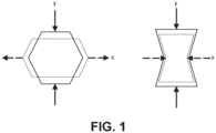
FIG. 1 is a schematic illustration comparing the properties of a non-auxetic material and an auxetic material. -
FIG. 2 is a simplified side view of a vane preform supported by an auxetic mandrel. -
FIG. 3 is a schematic cross-sectional illustration of a portion of the airfoil of the vane preform and auxetic mandrel. - While the above-identified figures set forth one or more embodiments of the present disclosure, other embodiments are also contemplated, as noted in the discussion. In all cases, this disclosure presents the invention by way of representation and not limitation. It should be understood that numerous other modifications and embodiments can be devised by those skilled in the art, which fall within the scope and spirit of the principles of the invention. The figures may not be drawn to scale, and applications and embodiments of the present invention may include features and components not specifically shown in the drawings.
- This disclosure presents auxetic tooling for use in the fabrication of CMC components.
FIG. 1 schematically illustrates properties of a non-auxetic, or conventional material (left) and an auxetic material (right) under a compressive force. The non-auxetic material on the left has a positive Poisson's ratio such that, when a uniaxial compressive force is applied in the y-direction, the non-auxetic material compresses/contracts in y-direction and expands in an orthogonal direction (e.g., the x-direction). The opposite can also be true as a uniaxial stretching force in the y-direction causes expansion in the y-direction and contraction in the x-direction. Conversely, the auxetic material on the right has a negative Poisson's ratio such that, when a uniaxial compressive force is applied in the y-direction, the auxetic material contracts in both the y-direction and the x-direction. If a uniaxial stretching force is instead applied in the y-direction, the auxetic material expands in both the y-direction and the x-direction. Accordingly, auxetic tooling, such as mandrels, can be used with and more easily removed from complexly shaped preforms, such as airfoils, due to their unique properties. -
FIG. 2 is a simplified side view ofauxetic mandrel 10 supportingceramic vane preform 12. Portions ofmandrel 10 are represented in dashed lines where internal to vane preform 12. Vanepreform 12 includesairfoil 14 extending between first, outer diameter (OD)platform 16 and second, inner diameter (ID)platform 18. Airfoil 14 includes leadingedge 20 and oppositely disposedtrailing edge 22.Airfoil 14 further includespressure sidewall 24 and oppositely disposed suction sidewall 26 (both shown and labeled inFIG. 3 ).Airfoil 14 may be complexly shaped with at least one internal cavity 28 (shown and labeled inFIG. 3 ) for improved aerodynamic performance. In an alternative embodiment,airfoil 14 can belong to a blade preform without departing from the scope of the invention.Vane preform 12 can be formed from fabrics, tapes, and/or braids of ceramic (e.g., silicon carbide) fibers arranged in various woven or non-woven architectures. The fibrous ceramic material can be laid up around/braided onmandrel 10 to form vane preform 12 in some embodiments. - Mandrel 10 can include first,
OD end 30 and second,ID end 32 corresponding to the relative locations of OD andID platforms mandrel 10 can correspond to the internal geometry of airfoil 14 (i.e., cavity 28). A compressive force can be applied to ID and OD ends 30 and 32 (i.e., in the y-direction) to cause contraction ofmandrel 10 in an orthogonal direction as is discussed in greater detail below. In an exemplary embodiment,mandrel 10 can be formed from graphene engineered for auxetic behavior. Due to the relatively high operational temperatures (i.e., above 1500°K) of graphene,mandrel 10 formed from graphene is ideally suited for use in a furnace/reactor, such as the type used in chemical vapor infiltration (CVI), melt infiltration (MI), and polymer infiltration and pyrolysis (PIP). Any of these methodologies can be used to densify vane preform 12 with a ceramic matrix. In such an embodiment, interconnected sheets of graphene can be 3D printed to formmandrel 10. - In an alternative embodiment,
mandrel 10 can instead be formed from an engineered metal, polymer, ceramic, or composite material. Any auxetic material used with an operational temperature below that of the CVI, MI, or PIP processes (i.e., approximately 1700°C, 1450°C, or 1050°C, respectively) can be instead formed into a preformingmandrel 10, which can be used through the preforming process to support a preform prior to the application of interface coatings (e.g., of boron nitride) via CVI and/or densification via CVI, MI, and/or PIP. In yet another alternative embodiment,mandrel 10 can be a hybrid mandrel with portions formed from an auxetic material, and portions formed from a non-auxetic material (e.g., graphite, refractory metals, carbon-carbon composite). -
FIG. 3 is a schematic cross-sectional illustration of a portion ofairfoil 14 in whichairfoil 14 is rotated roughly 90° from the view inFIG. 2 such thatpressure sidewall 24 andsuction sidewall 26 are visible, as well as airfoilinner cavity 28, in whichmandrel 10 is disposed.Mandrel 10 can extend at least the full length (i.e., in the y-direction) ofcavity 28. As shown inFIG. 3 ,suction sidewall 26 is curved (i.e., bowed) andmandrel 10 is correspondingly curved. Curvature creates flared region 36 insuction sidewall 26 which transitions into reducedthickness region 38, referring to the reduced distance betweensuction sidewall 26 andpressure sidewall 24. In order to sufficiently supportairfoil 14,mandrel 10 includes a corresponding flared region 40 and reducedthickness region 42, referring to the reduced region betweenwalls 44 ofmandrel 10. - Referring back to
FIG. 2 and with continued reference toFIG. 3 , ifmandrel 10 is extracted fromcavity 28 in the positive y-direction (based on the coordinates shown inFIG. 2 ), flared region 40 ofmandrel 10 is likely to contact/catch on reducedthickness region 38 ofairfoil 14. In such a scenario, a conventional graphite mandrel could potentially damage the internal surfaces ofairfoil 14 and/or fracture due to the brittle nature of graphite. However, withauxetic mandrel 10, a simultaneous compressive force can be applied to OD and ID ends 30 and 32 of mandrel 10 (i.e., in the y-direction) to causemandrel 10 to contract in the x-direction, creating deformed mandrel 10', represented inFIG. 3 with dashed lines. Stated another way, mandrel 10' can be deformed by compression in the y-direction to have a reduced cross-sectional profile along the x-direction, including flared region 40, which is consequently narrower than reducedthickness region 38 ofairfoil 14. This deformation facilitates its removal fromcavity 28 without damage to vane preform 12 ormandrel 10. In general,mandrel 10 can remain in the deformed state (i.e., as mandrel 10') so long as the compressive force is applied. Further, it should be noted thatmandrel 10 is generally removed fromvane preform 12 after densification with a matrix using one of the methodologies listed above if fabricated from an appropriate material, but a preforming-type mandrel 10 can be removed prior to application of interface coatings, if applicable, or densification. - In one example, the uniaxial compressive force can be applied by hand, in particular for a relatively
small vane preform 12. This can include an operator using both hands to apply the compressive force and extract mandrel 10' frominner cavity 28, as well as using a stationary object, such as a tabletop, to apply the compressive force at one end while the opposing compressive force is applied by hand. In a second example, a tool, and more specifically, a clamping tool (e.g., c-clamp, screw clamp, bar clamp, etc.) can be inserted through thehollow mandrel 10 and actuated to apply the compressive force. In an alternative embodiment, a clamping tool can be positioned externally to vane preform 12 to apply the uniaxial force tomandrel 10. - In an alternative embodiment,
mandrel 10 can be engineered to have a reduced cross-sectional profile along the z-direction shown inFIG. 2 in response to an applied uniaxial compressive force in the y-direction. This can occur in addition to, or alternatively to the reduction in the x-direction as shown inFIG. 3 depending on the material selected. Leadingedge 20 and/or trailingedge 22 can be complexly shaped (e.g., with tapering or curvature) creating correspondingly shaped surfaces ofinternal cavity 28. In such an embodiment, an applied uniaxial force in the y-direction can create a deformed mandrel 10' which is deformed along the z-direction. - The disclosed auxetic mandrel can be used in the fabrication of CMC components for use in aerospace, maritime, or industrial equipment, to name a few, non-limiting examples.
- The following are non-exclusive descriptions of possible embodiments of the present invention.
- A method of fabricating a ceramic matrix composite component includes fabricating a ceramic preform, the preform comprising a hollow portion with an internal cavity extending along a first axis from a first end to a second end of the hollow portion, supporting the hollow portion with an auxetic mandrel disposed within and the internal cavity and coaxial with the hollow portion, the auxetic mandrel comprising a first mandrel end and a second mandrel end, at least partially densifying the preform with a matrix, and removing the auxetic mandrel from the internal cavity by simultaneously applying a compressive force to each of the first mandrel end and the second mandrel end creating a deformed auxetic mandrel to reduce a cross-sectional profile of the auxetic mandrel along a second axis orthogonal to the first axis, and extracting the deformed auxetic mandrel from the first end of the hollow portion.
- The method of the preceding paragraph can optionally include, additionally and/or alternatively, any one or more of the following features, configurations and/or additional steps:
In the above method, the preform can be a vane preform and the hollow portion can be an airfoil. - In any of the above methods, the step of fabricating the ceramic preform can include laying up a ceramic material over the auxetic mandrel.
- In any of the above methods, the ceramic material can include silicon carbide fibers.
- In any of the above methods, the auxetic mandrel can be formed from graphene.
- In any of the above methods, the auxetic mandrel can be formed from one of a metal, a polymer, a ceramic, and a composite material.
- In any of the above methods, the step of at least partially densifying the preform with a ceramic matrix can be carried out using chemical vapor infiltration.
- In any of the above methods, the step of at least partially densifying the preform with a ceramic matrix can be carried out using polymer infiltration and pyrolysis or melt infiltration.
- In any of the above methods, the airfoil can include a first sidewall, a second sidewall, and a reduced thickness region therebetween.
- In any of the above methods, the auxetic mandrel can include a flared region corresponding to a flared region of the first sidewall.
- In any of the above methods, in the deformed auxetic mandrel, a cross-sectional profile of the flared region of the auxetic mandrel can be less than the reduced thickness region of the airfoil.
- In any of the above methods, the step of removing the auxetic mandrel from the airfoil can include moving the flared region of the auxetic mandrel through the reduced thickness region of the airfoil.
- In any of the above methods, the compressive force can be applied to each of the first mandrel end and the second mandrel end by hand.
- In any of the above methods, the compressive force can be applied to each of the first mandrel end and the second mandrel end using a tool.
- In any of the above methods, the tool can be a clamp.
- A deformable mandrel for use in fabricating a ceramic preform includes a body extending along a first axis between a first mandrel end and a second mandrel end. The body is formed from an auxetic material engineered to deform along a second axis orthogonal to the first axis when a uniaxial force is applied to the first mandrel end and the second mandrel end.
- The mandrel of the preceding paragraph can optionally include, additionally and/or alternatively, any one or more of the following features, configurations and/or additional components:
- In the above mandrel, the auxetic material can be graphene.
- In any of the above mandrels, the mandrel can be suitable for use in a furnace for at least one of a chemical vapor infiltration, polymer infiltration and pyrolysis, and melt infiltration process.
- In any of the above mandrels, the auxetic material can be one of a metal, a polymer, a ceramic, and a composite.
- In any of the above mandrels, the body can include a flared region and a reduced thickness region.
- While the invention has been described with reference to an exemplary embodiment(s), it will be understood by those skilled in the art that various changes may be made and equivalents may be substituted for elements thereof without departing from the scope of the invention. In addition, many modifications may be made to adapt a particular situation or material to the teachings of the invention without departing from the essential scope thereof. Therefore, it is intended that the invention not be limited to the particular embodiment(s) disclosed, but that the invention will include all embodiments falling within the scope of the appended claims.
Claims (15)
- A method of fabricating a ceramic matrix composite component, the method comprising:fabricating a ceramic preform (12), the preform (12) comprising a hollow portion with an internal cavity (28) extending along a first axis from a first end to a second end of the hollow portion;supporting the hollow portion with an auxetic mandrel (10) disposed within and the internal cavity (28) and coaxial with the hollow portion, the auxetic mandrel (10) comprising a first mandrel end (30) and a second mandrel end (32);at least partially densifying the preform (12) with a matrix; andremoving the auxetic mandrel (10) from the internal cavity (28) by:simultaneously applying a compressive force to each of the first mandrel end (30) and the second mandrel end (32) creating a deformed auxetic mandrel (10') to reduce a cross-sectional profile of the auxetic mandrel (10) along a second axis orthogonal to the first axis; andextracting the deformed auxetic mandrel (10') from the first end of the hollow portion.
- The method of claim 1, wherein the preform (12) is a vane preform, and wherein the hollow portion is an airfoil (14).
- The method of claim 2, wherein the airfoil (14) comprises:a first sidewall (26);a second sidewall (24); anda reduced thickness region (38) therebetween.
- The method of claim 3, wherein the auxetic mandrel (10) comprises a flared region (40) corresponding to a flared region (36) of the first sidewall (26).
- The method of claim 4, wherein in the deformed auxetic mandrel (10), a cross-sectional profile of the flared region (40) of the auxetic mandrel (10) is less than the reduced thickness region (38) of the airfoil (14).
- The method of claim 5, wherein the step of removing the auxetic mandrel (10) from the airfoil (14) comprises moving the flared region (40) of the auxetic mandrel (10) through the reduced thickness region (38) of the airfoil (14).
- The method of any preceding claim, wherein the step of fabricating the ceramic preform (12) comprises laying up a ceramic material over the auxetic mandrel (10),
wherein, optionally, the ceramic material comprises silicon carbide fibers. - The method of any preceding claim, wherein the auxetic mandrel (10) is formed from graphene.
- The method of any of claims 1 to 7, wherein the auxetic mandrel (10) is formed from one of a metal, a polymer, a ceramic, and a composite material.
- The method of any preceding claim, wherein:the step of at least partially densifying the preform (12) with a ceramic matrix is carried out using chemical vapor infiltration; orthe step of at least partially densifying the preform (12) with a ceramic matrix is carried out using polymer infiltration and pyrolysis or melt infiltration.
- The method of any preceding claim, wherein:the compressive force is applied to each of the first mandrel end (30) and the second mandrel end (32) by hand; orthe compressive force is applied to each of the first mandrel end (30) and the second mandrel end (32) using a tool, wherein, optionally, the tool is a clamp.
- A deformable mandrel (10) for use in fabricating a ceramic preform (12), the mandrel (10) comprising:a body extending along a first axis between a first mandrel end (30) and a second mandrel end (32),wherein the body is formed from an auxetic material engineered to deform along a second axis orthogonal to the first axis when a uniaxial force is applied to the first mandrel end (30) and the second mandrel end (32).
- The mandrel (10) of claim 12, wherein:the auxetic material is graphene; orthe auxetic material is one of a metal, a polymer, a ceramic, and a composite.
- The mandrel (10) of claim 12 or 13, wherein the mandrel (10) is suitable for use in a furnace for at least one of a chemical vapor infiltration, polymer infiltration and pyrolysis, and melt infiltration process.
- The mandrel (10) of claim 12, 13 or 14, wherein the body comprises a flared region (40) and a reduced thickness region (42).
Applications Claiming Priority (1)
| Application Number | Priority Date | Filing Date | Title |
|---|---|---|---|
| US18/371,070 US12435008B2 (en) | 2023-09-21 | 2023-09-21 | Auxetic materials and structures for ceramic matrix composite airfoil mandrels |
Publications (1)
| Publication Number | Publication Date |
|---|---|
| EP4527581A1 true EP4527581A1 (en) | 2025-03-26 |
Family
ID=91960640
Family Applications (1)
| Application Number | Title | Priority Date | Filing Date |
|---|---|---|---|
| EP24189773.5A Pending EP4527581A1 (en) | 2023-09-21 | 2024-07-19 | Deformable mandrel made of auxetic material and method of fabricating a ceramic matrix composite component using the same |
Country Status (2)
| Country | Link |
|---|---|
| US (1) | US12435008B2 (en) |
| EP (1) | EP4527581A1 (en) |
Citations (7)
| Publication number | Priority date | Publication date | Assignee | Title |
|---|---|---|---|---|
| US20020005605A1 (en) * | 1999-01-27 | 2002-01-17 | Dunyak Thomas J. | Method of removing cores from ceramic matrix composite articles |
| US20030175453A1 (en) * | 2001-01-25 | 2003-09-18 | Steffier Wayne S. | Actively-cooled fiber-reinforced ceramic matrix composite rocket propulsion thrust chamber and method of producing the same |
| GB2489457A (en) * | 2010-03-29 | 2012-10-03 | Univ Bolton | Method of preparing a morphable material |
| US20170057704A1 (en) * | 2015-08-26 | 2017-03-02 | The University Of New Hampshire | Chiral Structures With Adjustable Auxetic Effects |
| US20200392049A1 (en) * | 2019-05-13 | 2020-12-17 | Rolls-Royce Plc | Ceramic matrix composite vane with hybrid construction |
| EP4119772A1 (en) * | 2021-07-16 | 2023-01-18 | Raytheon Technologies Corporation | Airfoil assembly with fiber-reinforced composite rings and toothed exit slot |
| US20230189940A1 (en) * | 2021-12-16 | 2023-06-22 | Joon Bu Park | Negative poisson`s ratio materials for fasteners |
Family Cites Families (7)
| Publication number | Priority date | Publication date | Assignee | Title |
|---|---|---|---|---|
| US9617857B2 (en) | 2013-02-23 | 2017-04-11 | Rolls-Royce Corporation | Gas turbine engine component |
| US20150345320A1 (en) | 2013-03-13 | 2015-12-03 | United Technologies Corporation | Fan case with auxetic liner |
| US10605095B2 (en) * | 2016-05-11 | 2020-03-31 | General Electric Company | Ceramic matrix composite airfoil cooling |
| WO2019108203A1 (en) | 2017-11-30 | 2019-06-06 | Siemens Aktiengesellschaft | Hybrid ceramic matrix composite components with intermediate cushion structure |
| US10830102B2 (en) | 2018-03-01 | 2020-11-10 | General Electric Company | Casing with tunable lattice structure |
| GB201913394D0 (en) * | 2019-09-17 | 2019-10-30 | Rolls Royce Plc | A vane |
| US12104533B2 (en) | 2020-04-24 | 2024-10-01 | General Electric Company | Methods and apparatus for gas turbine frame flow path hardware cooling |
-
2023
- 2023-09-21 US US18/371,070 patent/US12435008B2/en active Active
-
2024
- 2024-07-19 EP EP24189773.5A patent/EP4527581A1/en active Pending
Patent Citations (7)
| Publication number | Priority date | Publication date | Assignee | Title |
|---|---|---|---|---|
| US20020005605A1 (en) * | 1999-01-27 | 2002-01-17 | Dunyak Thomas J. | Method of removing cores from ceramic matrix composite articles |
| US20030175453A1 (en) * | 2001-01-25 | 2003-09-18 | Steffier Wayne S. | Actively-cooled fiber-reinforced ceramic matrix composite rocket propulsion thrust chamber and method of producing the same |
| GB2489457A (en) * | 2010-03-29 | 2012-10-03 | Univ Bolton | Method of preparing a morphable material |
| US20170057704A1 (en) * | 2015-08-26 | 2017-03-02 | The University Of New Hampshire | Chiral Structures With Adjustable Auxetic Effects |
| US20200392049A1 (en) * | 2019-05-13 | 2020-12-17 | Rolls-Royce Plc | Ceramic matrix composite vane with hybrid construction |
| EP4119772A1 (en) * | 2021-07-16 | 2023-01-18 | Raytheon Technologies Corporation | Airfoil assembly with fiber-reinforced composite rings and toothed exit slot |
| US20230189940A1 (en) * | 2021-12-16 | 2023-06-22 | Joon Bu Park | Negative poisson`s ratio materials for fasteners |
Also Published As
| Publication number | Publication date |
|---|---|
| US20250100941A1 (en) | 2025-03-27 |
| US12435008B2 (en) | 2025-10-07 |
Similar Documents
| Publication | Publication Date | Title |
|---|---|---|
| EP2943448B1 (en) | Methods of forming ceramic matrix composite structures | |
| US9050769B2 (en) | Pre-form ceramic matrix composite cavity and method of forming and method of forming a ceramic matrix composite component | |
| US10011043B2 (en) | Method of producing an internal cavity in a ceramic matrix composite | |
| EP3054096A1 (en) | Ceramic matrix composite gas turbine engine blade | |
| US11117838B2 (en) | Method of making a fiber preform for ceramic matrix composite (CMC) fabrication | |
| JP6411894B2 (en) | Method of manufacturing a ceramic matrix composite and ceramic matrix composite formed thereby | |
| US12528228B2 (en) | Methods for complex geometry mandrel removal of ceramic matrix composite components | |
| US7550107B2 (en) | Method of forming CMC component | |
| JP6124529B2 (en) | Improved method of manufacturing parts having tubular geometry made from ceramic matrix composites | |
| EP4446076A1 (en) | A method of forming a ceramic matrix composite, and a pin array | |
| EP4541535A1 (en) | Z-channeling into a preform via needle perforation in a stand-alone tool | |
| EP4098417B1 (en) | Method of forming a ceramic matrix composite component having an internal cooling circuit | |
| EP4431254A2 (en) | Sheathed metallic needles for producing z-channels in fibrous preforms | |
| EP4454842A1 (en) | Z-channel creation in woven preform by incorporation of pin features into preform tooling | |
| US12435008B2 (en) | Auxetic materials and structures for ceramic matrix composite airfoil mandrels | |
| CN111039687B (en) | Damage-free hole making method for continuous fiber reinforced ceramic matrix composite | |
| EP3760604B1 (en) | Method of forming cooling channels in a ceramic matrix composite component | |
| JP2001206779A (en) | Method and apparatus for manufacturing fiber-reinforced composite member | |
| EP3284593A1 (en) | Hollow ceramic matrix composite article, mandrel for forming hollow ceramic matrix composite article, and method for forming hollow ceramic matrix composite article | |
| JP2020506866A (en) | Melt impregnation with SiGa and / or SiIn alloy | |
| JP5862234B2 (en) | Ceramic matrix composite member having smooth surface and method for producing the same | |
| EP4431483A1 (en) | Three dimensional weave with sacrifical z-fibers for improved ceramic matrix composite microstructure | |
| EP4144713A1 (en) | Localized pvb based tackifier application for cmc | |
| US20260091546A1 (en) | Single sided carbonization tooling for opf derived c/c | |
| EP4523895A2 (en) | Multi-mandrel braiding process |
Legal Events
| Date | Code | Title | Description |
|---|---|---|---|
| PUAI | Public reference made under article 153(3) epc to a published international application that has entered the european phase |
Free format text: ORIGINAL CODE: 0009012 |
|
| STAA | Information on the status of an ep patent application or granted ep patent |
Free format text: STATUS: THE APPLICATION HAS BEEN PUBLISHED |
|
| AK | Designated contracting states |
Kind code of ref document: A1 Designated state(s): AL AT BE BG CH CY CZ DE DK EE ES FI FR GB GR HR HU IE IS IT LI LT LU LV MC ME MK MT NL NO PL PT RO RS SE SI SK SM TR |
|
| STAA | Information on the status of an ep patent application or granted ep patent |
Free format text: STATUS: REQUEST FOR EXAMINATION WAS MADE |
|
| 17P | Request for examination filed |
Effective date: 20250926 |