EP3284593A1 - Hollow ceramic matrix composite article, mandrel for forming hollow ceramic matrix composite article, and method for forming hollow ceramic matrix composite article - Google Patents
Hollow ceramic matrix composite article, mandrel for forming hollow ceramic matrix composite article, and method for forming hollow ceramic matrix composite article Download PDFInfo
- Publication number
- EP3284593A1 EP3284593A1 EP17184632.2A EP17184632A EP3284593A1 EP 3284593 A1 EP3284593 A1 EP 3284593A1 EP 17184632 A EP17184632 A EP 17184632A EP 3284593 A1 EP3284593 A1 EP 3284593A1
- Authority
- EP
- European Patent Office
- Prior art keywords
- matrix composite
- ceramic matrix
- plies
- face
- ply
- Prior art date
- Legal status (The legal status is an assumption and is not a legal conclusion. Google has not performed a legal analysis and makes no representation as to the accuracy of the status listed.)
- Granted
Links
- 238000000034 method Methods 0.000 title claims abstract description 25
- 239000011153 ceramic matrix composite Substances 0.000 title claims description 129
- HBMJWWWQQXIZIP-UHFFFAOYSA-N silicon carbide Chemical compound [Si+]#[C-] HBMJWWWQQXIZIP-UHFFFAOYSA-N 0.000 claims description 16
- 229910010271 silicon carbide Inorganic materials 0.000 claims description 16
- 239000000463 material Substances 0.000 claims description 10
- 238000002844 melting Methods 0.000 claims description 8
- 230000008018 melting Effects 0.000 claims description 8
- 239000000203 mixture Substances 0.000 claims description 5
- OKTJSMMVPCPJKN-UHFFFAOYSA-N Carbon Chemical compound [C] OKTJSMMVPCPJKN-UHFFFAOYSA-N 0.000 claims description 4
- 229910052581 Si3N4 Inorganic materials 0.000 claims description 4
- XAGFODPZIPBFFR-UHFFFAOYSA-N aluminium Chemical compound [Al] XAGFODPZIPBFFR-UHFFFAOYSA-N 0.000 claims description 4
- 229910052782 aluminium Inorganic materials 0.000 claims description 4
- 229910052799 carbon Inorganic materials 0.000 claims description 4
- 239000011204 carbon fibre-reinforced silicon carbide Substances 0.000 claims description 4
- 230000001788 irregular Effects 0.000 claims description 4
- TWNQGVIAIRXVLR-UHFFFAOYSA-N oxo(oxoalumanyloxy)alumane Chemical compound O=[Al]O[Al]=O TWNQGVIAIRXVLR-UHFFFAOYSA-N 0.000 claims description 4
- HQVNEWCFYHHQES-UHFFFAOYSA-N silicon nitride Chemical compound N12[Si]34N5[Si]62N3[Si]51N64 HQVNEWCFYHHQES-UHFFFAOYSA-N 0.000 claims description 4
- 230000007423 decrease Effects 0.000 description 5
- 230000004048 modification Effects 0.000 description 5
- 238000012986 modification Methods 0.000 description 5
- 230000000052 comparative effect Effects 0.000 description 4
- 238000005452 bending Methods 0.000 description 2
- 238000002485 combustion reaction Methods 0.000 description 2
- ATJFFYVFTNAWJD-UHFFFAOYSA-N Tin Chemical compound [Sn] ATJFFYVFTNAWJD-UHFFFAOYSA-N 0.000 description 1
- 238000000576 coating method Methods 0.000 description 1
- 230000007547 defect Effects 0.000 description 1
- 238000000280 densification Methods 0.000 description 1
- 238000010438 heat treatment Methods 0.000 description 1
- 238000004519 manufacturing process Methods 0.000 description 1
- 229910000601 superalloy Inorganic materials 0.000 description 1
Images


Classifications
-
- F—MECHANICAL ENGINEERING; LIGHTING; HEATING; WEAPONS; BLASTING
- F01—MACHINES OR ENGINES IN GENERAL; ENGINE PLANTS IN GENERAL; STEAM ENGINES
- F01D—NON-POSITIVE DISPLACEMENT MACHINES OR ENGINES, e.g. STEAM TURBINES
- F01D5/00—Blades; Blade-carrying members; Heating, heat-insulating, cooling or antivibration means on the blades or the members
- F01D5/12—Blades
- F01D5/28—Selecting particular materials; Particular measures relating thereto; Measures against erosion or corrosion
- F01D5/282—Selecting composite materials, e.g. blades with reinforcing filaments
-
- C—CHEMISTRY; METALLURGY
- C04—CEMENTS; CONCRETE; ARTIFICIAL STONE; CERAMICS; REFRACTORIES
- C04B—LIME, MAGNESIA; SLAG; CEMENTS; COMPOSITIONS THEREOF, e.g. MORTARS, CONCRETE OR LIKE BUILDING MATERIALS; ARTIFICIAL STONE; CERAMICS; REFRACTORIES; TREATMENT OF NATURAL STONE
- C04B35/00—Shaped ceramic products characterised by their composition; Ceramics compositions; Processing powders of inorganic compounds preparatory to the manufacturing of ceramic products
- C04B35/01—Shaped ceramic products characterised by their composition; Ceramics compositions; Processing powders of inorganic compounds preparatory to the manufacturing of ceramic products based on oxide ceramics
- C04B35/10—Shaped ceramic products characterised by their composition; Ceramics compositions; Processing powders of inorganic compounds preparatory to the manufacturing of ceramic products based on oxide ceramics based on aluminium oxide
- C04B35/111—Fine ceramics
- C04B35/117—Composites
-
- B—PERFORMING OPERATIONS; TRANSPORTING
- B32—LAYERED PRODUCTS
- B32B—LAYERED PRODUCTS, i.e. PRODUCTS BUILT-UP OF STRATA OF FLAT OR NON-FLAT, e.g. CELLULAR OR HONEYCOMB, FORM
- B32B18/00—Layered products essentially comprising ceramics, e.g. refractory products
-
- B—PERFORMING OPERATIONS; TRANSPORTING
- B32—LAYERED PRODUCTS
- B32B—LAYERED PRODUCTS, i.e. PRODUCTS BUILT-UP OF STRATA OF FLAT OR NON-FLAT, e.g. CELLULAR OR HONEYCOMB, FORM
- B32B3/00—Layered products comprising a layer with external or internal discontinuities or unevennesses, or a layer of non-planar form; Layered products having particular features of form
- B32B3/26—Layered products comprising a layer with external or internal discontinuities or unevennesses, or a layer of non-planar form; Layered products having particular features of form characterised by a particular shape of the outline of the cross-section of a continuous layer; characterised by a layer with cavities or internal voids ; characterised by an apertured layer
-
- C—CHEMISTRY; METALLURGY
- C04—CEMENTS; CONCRETE; ARTIFICIAL STONE; CERAMICS; REFRACTORIES
- C04B—LIME, MAGNESIA; SLAG; CEMENTS; COMPOSITIONS THEREOF, e.g. MORTARS, CONCRETE OR LIKE BUILDING MATERIALS; ARTIFICIAL STONE; CERAMICS; REFRACTORIES; TREATMENT OF NATURAL STONE
- C04B35/00—Shaped ceramic products characterised by their composition; Ceramics compositions; Processing powders of inorganic compounds preparatory to the manufacturing of ceramic products
- C04B35/515—Shaped ceramic products characterised by their composition; Ceramics compositions; Processing powders of inorganic compounds preparatory to the manufacturing of ceramic products based on non-oxide ceramics
- C04B35/56—Shaped ceramic products characterised by their composition; Ceramics compositions; Processing powders of inorganic compounds preparatory to the manufacturing of ceramic products based on non-oxide ceramics based on carbides or oxycarbides
- C04B35/565—Shaped ceramic products characterised by their composition; Ceramics compositions; Processing powders of inorganic compounds preparatory to the manufacturing of ceramic products based on non-oxide ceramics based on carbides or oxycarbides based on silicon carbide
-
- C—CHEMISTRY; METALLURGY
- C04—CEMENTS; CONCRETE; ARTIFICIAL STONE; CERAMICS; REFRACTORIES
- C04B—LIME, MAGNESIA; SLAG; CEMENTS; COMPOSITIONS THEREOF, e.g. MORTARS, CONCRETE OR LIKE BUILDING MATERIALS; ARTIFICIAL STONE; CERAMICS; REFRACTORIES; TREATMENT OF NATURAL STONE
- C04B35/00—Shaped ceramic products characterised by their composition; Ceramics compositions; Processing powders of inorganic compounds preparatory to the manufacturing of ceramic products
- C04B35/515—Shaped ceramic products characterised by their composition; Ceramics compositions; Processing powders of inorganic compounds preparatory to the manufacturing of ceramic products based on non-oxide ceramics
- C04B35/58—Shaped ceramic products characterised by their composition; Ceramics compositions; Processing powders of inorganic compounds preparatory to the manufacturing of ceramic products based on non-oxide ceramics based on borides, nitrides, i.e. nitrides, oxynitrides, carbonitrides or oxycarbonitrides or silicides
- C04B35/584—Shaped ceramic products characterised by their composition; Ceramics compositions; Processing powders of inorganic compounds preparatory to the manufacturing of ceramic products based on non-oxide ceramics based on borides, nitrides, i.e. nitrides, oxynitrides, carbonitrides or oxycarbonitrides or silicides based on silicon nitride
-
- C—CHEMISTRY; METALLURGY
- C04—CEMENTS; CONCRETE; ARTIFICIAL STONE; CERAMICS; REFRACTORIES
- C04B—LIME, MAGNESIA; SLAG; CEMENTS; COMPOSITIONS THEREOF, e.g. MORTARS, CONCRETE OR LIKE BUILDING MATERIALS; ARTIFICIAL STONE; CERAMICS; REFRACTORIES; TREATMENT OF NATURAL STONE
- C04B35/00—Shaped ceramic products characterised by their composition; Ceramics compositions; Processing powders of inorganic compounds preparatory to the manufacturing of ceramic products
- C04B35/71—Ceramic products containing macroscopic reinforcing agents
- C04B35/78—Ceramic products containing macroscopic reinforcing agents containing non-metallic materials
- C04B35/80—Fibres, filaments, whiskers, platelets, or the like
- C04B35/83—Carbon fibres in a carbon matrix
-
- C—CHEMISTRY; METALLURGY
- C04—CEMENTS; CONCRETE; ARTIFICIAL STONE; CERAMICS; REFRACTORIES
- C04B—LIME, MAGNESIA; SLAG; CEMENTS; COMPOSITIONS THEREOF, e.g. MORTARS, CONCRETE OR LIKE BUILDING MATERIALS; ARTIFICIAL STONE; CERAMICS; REFRACTORIES; TREATMENT OF NATURAL STONE
- C04B37/00—Joining burned ceramic articles with other burned ceramic articles or other articles by heating
- C04B37/001—Joining burned ceramic articles with other burned ceramic articles or other articles by heating directly with other burned ceramic articles
-
- F—MECHANICAL ENGINEERING; LIGHTING; HEATING; WEAPONS; BLASTING
- F01—MACHINES OR ENGINES IN GENERAL; ENGINE PLANTS IN GENERAL; STEAM ENGINES
- F01D—NON-POSITIVE DISPLACEMENT MACHINES OR ENGINES, e.g. STEAM TURBINES
- F01D25/00—Component parts, details, or accessories, not provided for in, or of interest apart from, other groups
- F01D25/005—Selecting particular materials
-
- F—MECHANICAL ENGINEERING; LIGHTING; HEATING; WEAPONS; BLASTING
- F01—MACHINES OR ENGINES IN GENERAL; ENGINE PLANTS IN GENERAL; STEAM ENGINES
- F01D—NON-POSITIVE DISPLACEMENT MACHINES OR ENGINES, e.g. STEAM TURBINES
- F01D5/00—Blades; Blade-carrying members; Heating, heat-insulating, cooling or antivibration means on the blades or the members
- F01D5/12—Blades
- F01D5/14—Form or construction
- F01D5/147—Construction, i.e. structural features, e.g. of weight-saving hollow blades
-
- F—MECHANICAL ENGINEERING; LIGHTING; HEATING; WEAPONS; BLASTING
- F01—MACHINES OR ENGINES IN GENERAL; ENGINE PLANTS IN GENERAL; STEAM ENGINES
- F01D—NON-POSITIVE DISPLACEMENT MACHINES OR ENGINES, e.g. STEAM TURBINES
- F01D5/00—Blades; Blade-carrying members; Heating, heat-insulating, cooling or antivibration means on the blades or the members
- F01D5/12—Blades
- F01D5/28—Selecting particular materials; Particular measures relating thereto; Measures against erosion or corrosion
- F01D5/284—Selection of ceramic materials
-
- F—MECHANICAL ENGINEERING; LIGHTING; HEATING; WEAPONS; BLASTING
- F01—MACHINES OR ENGINES IN GENERAL; ENGINE PLANTS IN GENERAL; STEAM ENGINES
- F01D—NON-POSITIVE DISPLACEMENT MACHINES OR ENGINES, e.g. STEAM TURBINES
- F01D9/00—Stators
- F01D9/02—Nozzles; Nozzle boxes; Stator blades; Guide conduits, e.g. individual nozzles
- F01D9/04—Nozzles; Nozzle boxes; Stator blades; Guide conduits, e.g. individual nozzles forming ring or sector
- F01D9/041—Nozzles; Nozzle boxes; Stator blades; Guide conduits, e.g. individual nozzles forming ring or sector using blades
-
- B—PERFORMING OPERATIONS; TRANSPORTING
- B32—LAYERED PRODUCTS
- B32B—LAYERED PRODUCTS, i.e. PRODUCTS BUILT-UP OF STRATA OF FLAT OR NON-FLAT, e.g. CELLULAR OR HONEYCOMB, FORM
- B32B2603/00—Vanes, blades, propellers, rotors with blades
-
- C—CHEMISTRY; METALLURGY
- C04—CEMENTS; CONCRETE; ARTIFICIAL STONE; CERAMICS; REFRACTORIES
- C04B—LIME, MAGNESIA; SLAG; CEMENTS; COMPOSITIONS THEREOF, e.g. MORTARS, CONCRETE OR LIKE BUILDING MATERIALS; ARTIFICIAL STONE; CERAMICS; REFRACTORIES; TREATMENT OF NATURAL STONE
- C04B2235/00—Aspects relating to ceramic starting mixtures or sintered ceramic products
- C04B2235/02—Composition of constituents of the starting material or of secondary phases of the final product
- C04B2235/50—Constituents or additives of the starting mixture chosen for their shape or used because of their shape or their physical appearance
- C04B2235/52—Constituents or additives characterised by their shapes
- C04B2235/5208—Fibers
- C04B2235/5216—Inorganic
- C04B2235/522—Oxidic
- C04B2235/5224—Alumina or aluminates
-
- C—CHEMISTRY; METALLURGY
- C04—CEMENTS; CONCRETE; ARTIFICIAL STONE; CERAMICS; REFRACTORIES
- C04B—LIME, MAGNESIA; SLAG; CEMENTS; COMPOSITIONS THEREOF, e.g. MORTARS, CONCRETE OR LIKE BUILDING MATERIALS; ARTIFICIAL STONE; CERAMICS; REFRACTORIES; TREATMENT OF NATURAL STONE
- C04B2235/00—Aspects relating to ceramic starting mixtures or sintered ceramic products
- C04B2235/02—Composition of constituents of the starting material or of secondary phases of the final product
- C04B2235/50—Constituents or additives of the starting mixture chosen for their shape or used because of their shape or their physical appearance
- C04B2235/52—Constituents or additives characterised by their shapes
- C04B2235/5208—Fibers
- C04B2235/5216—Inorganic
- C04B2235/524—Non-oxidic, e.g. borides, carbides, silicides or nitrides
- C04B2235/5244—Silicon carbide
-
- C—CHEMISTRY; METALLURGY
- C04—CEMENTS; CONCRETE; ARTIFICIAL STONE; CERAMICS; REFRACTORIES
- C04B—LIME, MAGNESIA; SLAG; CEMENTS; COMPOSITIONS THEREOF, e.g. MORTARS, CONCRETE OR LIKE BUILDING MATERIALS; ARTIFICIAL STONE; CERAMICS; REFRACTORIES; TREATMENT OF NATURAL STONE
- C04B2235/00—Aspects relating to ceramic starting mixtures or sintered ceramic products
- C04B2235/02—Composition of constituents of the starting material or of secondary phases of the final product
- C04B2235/50—Constituents or additives of the starting mixture chosen for their shape or used because of their shape or their physical appearance
- C04B2235/52—Constituents or additives characterised by their shapes
- C04B2235/5208—Fibers
- C04B2235/5216—Inorganic
- C04B2235/524—Non-oxidic, e.g. borides, carbides, silicides or nitrides
- C04B2235/5248—Carbon, e.g. graphite
-
- C—CHEMISTRY; METALLURGY
- C04—CEMENTS; CONCRETE; ARTIFICIAL STONE; CERAMICS; REFRACTORIES
- C04B—LIME, MAGNESIA; SLAG; CEMENTS; COMPOSITIONS THEREOF, e.g. MORTARS, CONCRETE OR LIKE BUILDING MATERIALS; ARTIFICIAL STONE; CERAMICS; REFRACTORIES; TREATMENT OF NATURAL STONE
- C04B2235/00—Aspects relating to ceramic starting mixtures or sintered ceramic products
- C04B2235/60—Aspects relating to the preparation, properties or mechanical treatment of green bodies or pre-forms
- C04B2235/602—Making the green bodies or pre-forms by moulding
- C04B2235/6028—Shaping around a core which is removed later
-
- C—CHEMISTRY; METALLURGY
- C04—CEMENTS; CONCRETE; ARTIFICIAL STONE; CERAMICS; REFRACTORIES
- C04B—LIME, MAGNESIA; SLAG; CEMENTS; COMPOSITIONS THEREOF, e.g. MORTARS, CONCRETE OR LIKE BUILDING MATERIALS; ARTIFICIAL STONE; CERAMICS; REFRACTORIES; TREATMENT OF NATURAL STONE
- C04B2237/00—Aspects relating to ceramic laminates or to joining of ceramic articles with other articles by heating
- C04B2237/30—Composition of layers of ceramic laminates or of ceramic or metallic articles to be joined by heating, e.g. Si substrates
- C04B2237/32—Ceramic
- C04B2237/34—Oxidic
- C04B2237/343—Alumina or aluminates
-
- C—CHEMISTRY; METALLURGY
- C04—CEMENTS; CONCRETE; ARTIFICIAL STONE; CERAMICS; REFRACTORIES
- C04B—LIME, MAGNESIA; SLAG; CEMENTS; COMPOSITIONS THEREOF, e.g. MORTARS, CONCRETE OR LIKE BUILDING MATERIALS; ARTIFICIAL STONE; CERAMICS; REFRACTORIES; TREATMENT OF NATURAL STONE
- C04B2237/00—Aspects relating to ceramic laminates or to joining of ceramic articles with other articles by heating
- C04B2237/30—Composition of layers of ceramic laminates or of ceramic or metallic articles to be joined by heating, e.g. Si substrates
- C04B2237/32—Ceramic
- C04B2237/36—Non-oxidic
- C04B2237/365—Silicon carbide
-
- C—CHEMISTRY; METALLURGY
- C04—CEMENTS; CONCRETE; ARTIFICIAL STONE; CERAMICS; REFRACTORIES
- C04B—LIME, MAGNESIA; SLAG; CEMENTS; COMPOSITIONS THEREOF, e.g. MORTARS, CONCRETE OR LIKE BUILDING MATERIALS; ARTIFICIAL STONE; CERAMICS; REFRACTORIES; TREATMENT OF NATURAL STONE
- C04B2237/00—Aspects relating to ceramic laminates or to joining of ceramic articles with other articles by heating
- C04B2237/30—Composition of layers of ceramic laminates or of ceramic or metallic articles to be joined by heating, e.g. Si substrates
- C04B2237/32—Ceramic
- C04B2237/36—Non-oxidic
- C04B2237/368—Silicon nitride
-
- C—CHEMISTRY; METALLURGY
- C04—CEMENTS; CONCRETE; ARTIFICIAL STONE; CERAMICS; REFRACTORIES
- C04B—LIME, MAGNESIA; SLAG; CEMENTS; COMPOSITIONS THEREOF, e.g. MORTARS, CONCRETE OR LIKE BUILDING MATERIALS; ARTIFICIAL STONE; CERAMICS; REFRACTORIES; TREATMENT OF NATURAL STONE
- C04B2237/00—Aspects relating to ceramic laminates or to joining of ceramic articles with other articles by heating
- C04B2237/30—Composition of layers of ceramic laminates or of ceramic or metallic articles to be joined by heating, e.g. Si substrates
- C04B2237/32—Ceramic
- C04B2237/38—Fiber or whisker reinforced
- C04B2237/385—Carbon or carbon composite
-
- F—MECHANICAL ENGINEERING; LIGHTING; HEATING; WEAPONS; BLASTING
- F05—INDEXING SCHEMES RELATING TO ENGINES OR PUMPS IN VARIOUS SUBCLASSES OF CLASSES F01-F04
- F05D—INDEXING SCHEME FOR ASPECTS RELATING TO NON-POSITIVE-DISPLACEMENT MACHINES OR ENGINES, GAS-TURBINES OR JET-PROPULSION PLANTS
- F05D2220/00—Application
- F05D2220/30—Application in turbines
- F05D2220/32—Application in turbines in gas turbines
-
- F—MECHANICAL ENGINEERING; LIGHTING; HEATING; WEAPONS; BLASTING
- F05—INDEXING SCHEMES RELATING TO ENGINES OR PUMPS IN VARIOUS SUBCLASSES OF CLASSES F01-F04
- F05D—INDEXING SCHEME FOR ASPECTS RELATING TO NON-POSITIVE-DISPLACEMENT MACHINES OR ENGINES, GAS-TURBINES OR JET-PROPULSION PLANTS
- F05D2300/00—Materials; Properties thereof
- F05D2300/60—Properties or characteristics given to material by treatment or manufacturing
- F05D2300/603—Composites; e.g. fibre-reinforced
- F05D2300/6033—Ceramic matrix composites [CMC]
Definitions
- the present invention is directed to hollow ceramic matrix composite (CMC) articles, mandrels for forming hollow CMC articles, and methods for forming hollow CMC articles. More particularly, the present invention is directed to hollow CMC articles, mandrels for forming hollow CMC articles, and methods for forming hollow CMC articles including a curve having a single turning point.
- CMC hollow ceramic matrix composite
- Gas turbines are continuously being modified to provide increased efficiency and performance. These modifications include the ability to operate at higher temperatures and under harsher conditions, which often requires material modifications and/or coatings to protect components from such temperatures and conditions. As more modifications are introduced, additional challenges are realized.
- gas turbine components such as, but not limited to, airfoils, buckets (blades), nozzles (vanes), combustion liners, and shrouds from CMC.
- CMC materials may be more susceptible to bending stresses and deformation than other structural materials such as superalloys. Therefore, for components which include hollow spaces, a wrap layer of CMC may be incorporated in order to stabilize the structure surrounding the hollow spaces.
- the CMC plies of the wrap layer may be susceptible to fraying prior to densification, particularly at each turning point of the CMC plies about the hollow spaces.
- a hollow CMC article includes a ply-wrap layer defining a cavity disposed within the ply-wrap layer.
- the ply-wrap layer includes a first face, a second face, a root portion bridging the first face and the second face, and a plurality of CMC wrap plies.
- the root portion defines a terminus of the ply-wrap layer including a cross-sectional conformation, and the cross-sectional conformation consists of a curve having a single turning point.
- Each of the plurality of CMC wrap plies is disposed along the first face, wrap over the root portion, and extend along the second face.
- the hollow article further includes a plurality of CMC lateral plies disposed along at least one of the first face and the second face.
- a ply-support mandrel for forming a hollow CMC article includes a first face support, a second face support, and a root portion support bridging the first face support and the second face support.
- the root portion support defines a mandrel terminus, and includes a cross-sectional conformation.
- the cross-sectional conformation consists of a curve having a single turning point.
- a method for forming a hollow CMC article includes applying a plurality of CMC wrap plies to a ply-support mandrel. Applying the plurality of CMC wrap plies includes wrapping each of the plurality of CMC wrap plies along a first face support and a second face support of the mandrel and over a root portion support of the mandrel bridging the first face support and the second face support, and forming a ply-wrap layer supported on the mandrel.
- the ply-wrap layer includes a first face, a second face, and a root portion bridging the first face and the second face.
- the root portion support includes a cross-sectional conformation consisting of a curve having a single turning point.
- a plurality of CMC lateral plies is applied along at least one of the first face and the second face.
- the plurality of CMC wrap plies and the plurality of CMC lateral plies are consolidated, pyrolized, and densified.
- the mandrel is removed, forming a cavity disposed within the ply-wrap layer.
- hollow CMC articles mandrels for forming hollow CMC articles, and methods for forming hollow CMC articles.
- Embodiments of the present disclosure in comparison to processes not utilizing one or more features disclosed herein, decrease costs, decrease weight, increase process efficiency, increase production yield, increase strength, increase shear area, increase radial cross-sectional stiffness, decrease ply fraying, decrease deformation susceptibility, increase operating lifetime, or a combination thereof.
- a hollow CMC article 100 includes a ply-wrap layer 102 defining a cavity 104 disposed within the ply-wrap layer 102.
- the ply-wrap layer includes a first face 106, a second face 108, a root portion 110 bridging the first face 106 and the second face 108, and a plurality of ceramic matrix composite wrap plies 112.
- the root portion 110 defines a terminus 114 of the ply-wrap layer 102 including a cross-sectional conformation 116, and the cross-sectional conformation 116 consists of a curve 118 having a single turning point 120.
- Each of the plurality of CMC wrap plies 112 is disposed along the first face 106, wraps over the root portion 110, and extends along the second face 108.
- the article 100 further includes a plurality CMC lateral plies 122 disposed along at least one of the first face 106 and the second face 108.
- the article may also include a plurality of CMC root plies 124 aligned with the plurality of CMC lateral plies 122 wherein each of the plurality of CMC root plies 124 includes a ply terminus 126 abutting the root portion 110 of the ply-wrap layer 102.
- the cavity 104 may be partially open to an external environment or the cavity 104 may be fully enclosed.
- the CMC article 100 may also include (not shown) additional CMC plies which do not extend along with first face 106 or the second face 108, and which do not include a ply terminus 126 abutting the root portion 110 of the ply-wrap layer 102.
- the ply terminus 126 of each of the plurality of CMC root plies 124 may be staggered relative to one another along the root portion 110. Without being bound by theory, it is believed that staggering the ply termini 126 of the plurality of CMC root plies 124 relative to one another increases the shear area along the root portion and increases tolerance for lateral loads in comparison to a comparative embodiment (not shown) in which the ply termini 126 are substantially even along the root portion 110.
- the plurality of CMC wrap plies 112, the plurality of CMC lateral plies 122, and, if present, the plurality of CMC root plies may independently include any suitable CMC composition.
- suitable CMC compositions include, but are not limited to, aluminum oxide-fiber-reinforced aluminum oxide (Ox/Ox), carbon-fiber-reinforced carbon (C/C), carbon-fiber-reinforced silicon carbide (C/SiC), silicon-carbide-fiber-reinforced silicon carbide (SiC/SiC), carbon-fiber-reinforced silicon nitride (C/SiN), and combinations thereof.
- the curve 118 may be any suitable curve 118 provided that curve 118 has only the single turning point 120.
- "turning point” is defined as a point along the curve 118 at which the curvature of the curve 118 is a local maximum for a change of direction of at least about 30°, except that for a curve 118 which is a circular segment, or a portion of the curve 118 which is a circular segment changing direction by at least about 30°, the "turning point" is the point along the circular segment halfway between the beginning and end of the circular segment. Further, sequential changes of direction of less than 30° considered as a single change of direction having an averaged curvature.
- Suitable curves 118 may include, but are not limited to, irregular curves, circular segments, parabolic segments, elliptical segments, and combinations thereof.
- the curve 118 of the cross-sectional conformation 116 may vary across the root portion 110, for example across the root portion 110 in a direction orthogonal to the cross-section of FIG. 1 .
- the curve 118 may include any suitable minimum radius of curvature 128.
- the minimum radius of curvature 128 is at least about 1 mm, alternatively at least about 2 mm, alternatively at least about 3 mm, alternatively at least about 4 mm, alternatively at least about 5 mm, alternatively at least about 10 mm.
- the minimum radius of curvature 128 may vary across the root portion 110, for example across the root portion 110 in a direction orthogonal to the cross-section of FIG. 1 .
- the article 100 may be any suitable article.
- the article 100 is a turbine component.
- Suitable turbine components may include, but are not limited to, airfoils (shown), buckets (blades), nozzles (vanes), combustion liners, and shrouds.
- a method for forming the hollow CMC article 100 includes the use of a ply-support mandrel 200.
- the mandrel 200 includes a first face support 202, a second face support 204, and a root portion support 206 bridging the first face support 202 and the second face support 204.
- the root portion support 206 defines a mandrel terminus 208, and includes a cross-sectional conformation 116.
- the cross-sectional conformation 116 consists of a curve 118 having a single turning point 120.
- the mandrel 200 may be formed of any suitable material.
- the material includes a melting point of less than about 235 °C, alternatively less than about 232 °C, alternatively less than about 230 °C. In another embodiment the material includes a melting point of less than about 330 °C, alternatively less than about 328 °C, alternatively less than about 325 °C. Suitable materials include, but are not limited to, tin, lead, and combinations thereof.
- the method further includes applying a plurality of CMC wrap plies 112 to the mandrel 200.
- Applying the plurality of CMC wrap plies 112 includes wrapping each of the plurality of CMC wrap plies 112 along the first face support 202, over the root portion support 206, and along the second face support 204, forming the ply-wrap layer 102 supported on the mandrel 200.
- the method further includes applying a plurality of CMC lateral plies 122 along at least one of the first face 106 and the second face 108.
- the method may also include applying a plurality of CMC root plies 124 aligned with the plurality of CMC lateral plies 122 with the ply termini 126 of the plurality of CMC root plies 124 abutting against the root portion 110 of the ply-wrap layer 102.
- the method further includes consolidating, pyrolizing, and densifying the plurality of CMC wrap plies 112, the plurality of CMC lateral plies 122, and, if present, the plurality of CMC root plies 124, and removing the mandrel 200 to form the article 100 having the cavity 104 disposed within the ply-wrap layer 102.
- the plurality of CMC lateral plies 122, and, if present, the plurality of CMC root plies 124 is complete, at least one additional ply is applied or at least one of the plurality of CMC wrap plies 112, the plurality of CMC lateral plies 122, and, if present, the plurality of CMC root plies 124, is manipulated to fully enclose the cavity 104.
- the fully enclosed cavity 104 is hermetically sealed.
- removing the mandrel 200 includes melting the mandrel 200 while pyrolizing the plurality of CMC wrap plies 112. Melting the mandrel 200 may include heating the mandrel to any suitable temperature, including, but not limited to, a temperature of at least about 230 °C, alternatively at least about 232 °C, alternatively at least about 235 °C, alternatively at least about 325 °C, alternatively at least about 328 °C, alternatively at least about 330 °C.
Abstract
Description
- The present invention is directed to hollow ceramic matrix composite (CMC) articles, mandrels for forming hollow CMC articles, and methods for forming hollow CMC articles. More particularly, the present invention is directed to hollow CMC articles, mandrels for forming hollow CMC articles, and methods for forming hollow CMC articles including a curve having a single turning point.
- Gas turbines are continuously being modified to provide increased efficiency and performance. These modifications include the ability to operate at higher temperatures and under harsher conditions, which often requires material modifications and/or coatings to protect components from such temperatures and conditions. As more modifications are introduced, additional challenges are realized.
- One modification to increase performance and efficiency involves forming gas turbine components, such as, but not limited to, airfoils, buckets (blades), nozzles (vanes), combustion liners, and shrouds from CMC. However, CMC materials may be more susceptible to bending stresses and deformation than other structural materials such as superalloys. Therefore, for components which include hollow spaces, a wrap layer of CMC may be incorporated in order to stabilize the structure surrounding the hollow spaces. However, the CMC plies of the wrap layer may be susceptible to fraying prior to densification, particularly at each turning point of the CMC plies about the hollow spaces.
- In an exemplary embodiment, a hollow CMC article includes a ply-wrap layer defining a cavity disposed within the ply-wrap layer. The ply-wrap layer includes a first face, a second face, a root portion bridging the first face and the second face, and a plurality of CMC wrap plies. The root portion defines a terminus of the ply-wrap layer including a cross-sectional conformation, and the cross-sectional conformation consists of a curve having a single turning point. Each of the plurality of CMC wrap plies is disposed along the first face, wrap over the root portion, and extend along the second face. The hollow article further includes a plurality of CMC lateral plies disposed along at least one of the first face and the second face.
- In another exemplary embodiment, a ply-support mandrel for forming a hollow CMC article includes a first face support, a second face support, and a root portion support bridging the first face support and the second face support. The root portion support defines a mandrel terminus, and includes a cross-sectional conformation. The cross-sectional conformation consists of a curve having a single turning point.
- In another exemplary embodiment, a method for forming a hollow CMC article includes applying a plurality of CMC wrap plies to a ply-support mandrel. Applying the plurality of CMC wrap plies includes wrapping each of the plurality of CMC wrap plies along a first face support and a second face support of the mandrel and over a root portion support of the mandrel bridging the first face support and the second face support, and forming a ply-wrap layer supported on the mandrel. The ply-wrap layer includes a first face, a second face, and a root portion bridging the first face and the second face. The root portion support includes a cross-sectional conformation consisting of a curve having a single turning point. A plurality of CMC lateral plies is applied along at least one of the first face and the second face. The plurality of CMC wrap plies and the plurality of CMC lateral plies are consolidated, pyrolized, and densified. The mandrel is removed, forming a cavity disposed within the ply-wrap layer.
- Other features and advantages of the present invention will be apparent from the following more detailed description of the preferred embodiment, taken in conjunction with the accompanying drawings, which illustrate, by way of example, the principles of the invention.
-
-
FIG. 1 is a cross-sectional view of a hollow CMC article, according to an embodiment of the present disclosure. -
FIG. 2 is a perspective view of a mandrel, according to an embodiment of the present disclosure. -
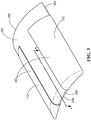
FIG. 3 is a perspective view of the mandrel ofFIG. 2 wrapped with CMC wrap plies, according to an embodiment of the present disclosure. -
FIG. 4 is a cross-sectional view of the mandrel ofFIG. 3 taken along 4-4, but with CMC lateral plies and CMC root plies laid up along the CMC wrap plies, according to an embodiment of the present disclosure. - Wherever possible, the same reference numbers will be used throughout the drawings to represent the same parts.
- Provided are hollow CMC articles, mandrels for forming hollow CMC articles, and methods for forming hollow CMC articles. Embodiments of the present disclosure, in comparison to processes not utilizing one or more features disclosed herein, decrease costs, decrease weight, increase process efficiency, increase production yield, increase strength, increase shear area, increase radial cross-sectional stiffness, decrease ply fraying, decrease deformation susceptibility, increase operating lifetime, or a combination thereof.
- Referring to
FIG. 1 , in one embodiment, ahollow CMC article 100 includes a ply-wrap layer 102 defining acavity 104 disposed within the ply-wrap layer 102. The ply-wrap layer includes afirst face 106, asecond face 108, aroot portion 110 bridging thefirst face 106 and thesecond face 108, and a plurality of ceramic matrixcomposite wrap plies 112. Theroot portion 110 defines aterminus 114 of the ply-wrap layer 102 including across-sectional conformation 116, and thecross-sectional conformation 116 consists of acurve 118 having asingle turning point 120. Each of the plurality ofCMC wrap plies 112 is disposed along thefirst face 106, wraps over theroot portion 110, and extends along thesecond face 108. Thearticle 100 further includes a plurality CMClateral plies 122 disposed along at least one of thefirst face 106 and thesecond face 108. The article may also include a plurality ofCMC root plies 124 aligned with the plurality of CMClateral plies 122 wherein each of the plurality ofCMC root plies 124 includes aply terminus 126 abutting theroot portion 110 of the ply-wrap layer 102. Thecavity 104 may be partially open to an external environment or thecavity 104 may be fully enclosed. TheCMC article 100 may also include (not shown) additional CMC plies which do not extend along withfirst face 106 or thesecond face 108, and which do not include aply terminus 126 abutting theroot portion 110 of the ply-wrap layer 102. - The
ply terminus 126 of each of the plurality ofCMC root plies 124 may be staggered relative to one another along theroot portion 110. Without being bound by theory, it is believed that staggering theply termini 126 of the plurality ofCMC root plies 124 relative to one another increases the shear area along the root portion and increases tolerance for lateral loads in comparison to a comparative embodiment (not shown) in which theply termini 126 are substantially even along theroot portion 110. - The plurality of
CMC wrap plies 112, the plurality of CMClateral plies 122, and, if present, the plurality of CMC root plies may independently include any suitable CMC composition. Suitable CMC compositions include, but are not limited to, aluminum oxide-fiber-reinforced aluminum oxide (Ox/Ox), carbon-fiber-reinforced carbon (C/C), carbon-fiber-reinforced silicon carbide (C/SiC), silicon-carbide-fiber-reinforced silicon carbide (SiC/SiC), carbon-fiber-reinforced silicon nitride (C/SiN), and combinations thereof. - The
curve 118 may be anysuitable curve 118 provided thatcurve 118 has only thesingle turning point 120. As used herein, "turning point" is defined as a point along thecurve 118 at which the curvature of thecurve 118 is a local maximum for a change of direction of at least about 30°, except that for acurve 118 which is a circular segment, or a portion of thecurve 118 which is a circular segment changing direction by at least about 30°, the "turning point" is the point along the circular segment halfway between the beginning and end of the circular segment. Further, sequential changes of direction of less than 30° considered as a single change of direction having an averaged curvature. However, the limitation of only asingle turning point 120 of thecurve 118 does not exclude the presence of surface defects or textures, which are not considered to be deviations from thecurve 118 orturning points 120.Suitable curves 118 may include, but are not limited to, irregular curves, circular segments, parabolic segments, elliptical segments, and combinations thereof. Thecurve 118 of thecross-sectional conformation 116 may vary across theroot portion 110, for example across theroot portion 110 in a direction orthogonal to the cross-section ofFIG. 1 . - The
curve 118 may include any suitable minimum radius ofcurvature 128. In one embodiment, the minimum radius ofcurvature 128 is at least about 1 mm, alternatively at least about 2 mm, alternatively at least about 3 mm, alternatively at least about 4 mm, alternatively at least about 5 mm, alternatively at least about 10 mm. The minimum radius ofcurvature 128 may vary across theroot portion 110, for example across theroot portion 110 in a direction orthogonal to the cross-section ofFIG. 1 . Without being bound by theory, it is believed that having only asingle turning point 120 along thecurve 118 of theroot portion 110 bridging thefirst face 106 to thesecond face 108, as opposed to two essentially right-angled turning points in a comparative example (not shown), provides a larger minimum radius ofcurvature 128 along thecurve 118 than would be included in the comparative example havingmultiple turning points 120, and thereby decreases localized bending stress on the plurality ofCMC wrap plies 112, reducing or eliminating fraying relative to the comparative example. - The
article 100 may be any suitable article. In one embodiment, thearticle 100 is a turbine component. Suitable turbine components may include, but are not limited to, airfoils (shown), buckets (blades), nozzles (vanes), combustion liners, and shrouds. - Referring to
FIG. 2 , in one embodiment, a method for forming the hollow CMC article 100 (as shown inFIG. 1 ) includes the use of a ply-support mandrel 200. Themandrel 200 includes afirst face support 202, asecond face support 204, and aroot portion support 206 bridging thefirst face support 202 and thesecond face support 204. Theroot portion support 206 defines amandrel terminus 208, and includes across-sectional conformation 116. Thecross-sectional conformation 116 consists of acurve 118 having asingle turning point 120. Themandrel 200 may be formed of any suitable material. In one embodiment the material includes a melting point of less than about 235 °C, alternatively less than about 232 °C, alternatively less than about 230 °C. In another embodiment the material includes a melting point of less than about 330 °C, alternatively less than about 328 °C, alternatively less than about 325 °C. Suitable materials include, but are not limited to, tin, lead, and combinations thereof. - Referring to
FIG. 3 , the method further includes applying a plurality of CMC wrap plies 112 to themandrel 200. Applying the plurality of CMC wrap plies 112 includes wrapping each of the plurality of CMC wrap plies 112 along thefirst face support 202, over theroot portion support 206, and along thesecond face support 204, forming the ply-wrap layer 102 supported on themandrel 200. - Referring to
FIG. 4 , the method further includes applying a plurality of CMC lateral plies 122 along at least one of thefirst face 106 and thesecond face 108. The method may also include applying a plurality of CMC root plies 124 aligned with the plurality of CMC lateral plies 122 with the ply termini 126 of the plurality of CMC root plies 124 abutting against theroot portion 110 of the ply-wrap layer 102. - Referring to
FIG. 1 , the method further includes consolidating, pyrolizing, and densifying the plurality of CMC wrap plies 112, the plurality of CMC lateral plies 122, and, if present, the plurality of CMC root plies 124, and removing themandrel 200 to form thearticle 100 having thecavity 104 disposed within the ply-wrap layer 102. In one embodiment (not shown), after removing themandrel 200 but before the densifying of the plurality of CMC wrap plies 112, the plurality of CMC lateral plies 122, and, if present, the plurality of CMC root plies 124, is complete, at least one additional ply is applied or at least one of the plurality of CMC wrap plies 112, the plurality of CMC lateral plies 122, and, if present, the plurality of CMC root plies 124, is manipulated to fully enclose thecavity 104. In a further embodiment (not shown), the fullyenclosed cavity 104 is hermetically sealed. - In one embodiment, removing the
mandrel 200 includes melting themandrel 200 while pyrolizing the plurality of CMC wrap plies 112. Melting themandrel 200 may include heating the mandrel to any suitable temperature, including, but not limited to, a temperature of at least about 230 °C, alternatively at least about 232 °C, alternatively at least about 235 °C, alternatively at least about 325 °C, alternatively at least about 328 °C, alternatively at least about 330 °C. - While the invention has been described with reference to a preferred embodiment, it will be understood by those skilled in the art that various changes may be made and equivalents may be substituted for elements thereof without departing from the scope of the invention. In addition, many modifications may be made to adapt a particular situation or material to the teachings of the invention without departing from the essential scope thereof. Therefore, it is intended that the invention not be limited to the particular embodiment disclosed as the best mode contemplated for carrying out this invention, but that the invention will include all embodiments falling within the scope of the appended claims.
- Various aspects and embodiments of the present invention are defined by the following numbered clauses:
- 1. A hollow ceramic matrix composite article, comprising:
- a ply-wrap layer defining a cavity disposed within the ply-wrap layer, the ply-wrap layer including:
- a first face;
- a second face;
- a root portion bridging the first face and the second face, the root portion defining a terminus of the ply-wrap layer including a cross-sectional conformation, the cross-sectional conformation consisting of a curve having a single turning point; and
- a plurality of ceramic matrix composite wrap plies, each of the plurality of ceramic matrix composite wrap plies being disposed along the first face, wrapping over the root portion, and extending along the second face; and
- a plurality of ceramic matrix composite lateral plies disposed along at least one of the first face and the second face.
- a ply-wrap layer defining a cavity disposed within the ply-wrap layer, the ply-wrap layer including:
- 2. The article of clause 1, further including a plurality of ceramic matrix composite root plies aligned with the plurality of ceramic matrix composite lateral plies, each of the plurality of ceramic matrix composite root plies including a ply terminus abutting the root portion of the ply-wrap layer, wherein the ply terminus of each of the plurality of ceramic matrix composite root plies are staggered relative to one another along the root portion.
- 3. The article of any preceding clause, wherein the plurality of ceramic matrix composite wrap plies and the plurality of ceramic matrix composite lateral plies independently include a ceramic matrix composite composition selected from the group consisting of an aluminum oxide-fiber-reinforced aluminum oxide (Ox/Ox), a carbon-fiber-reinforced carbon (C/C), a carbon-fiber-reinforced silicon carbide (C/SiC), a silicon-carbide-fiber-reinforced silicon carbide (SiC/SiC), a carbon-fiber-reinforced silicon nitride (C/SiN), and combinations thereof
- 4. The article of any preceding clause, wherein the hollow article is a turbine component.
- 5. The article of any preceding clause, wherein the turbine component is an airfoil.
- 6. The article of any preceding clause, wherein the curve is selected from the group consisting of an irregular curve, a circular segment, a parabolic segment, an elliptical segment, and combinations thereof.
- 7. The article of any preceding clause, wherein the curve includes a minimum radius of curvature of at least about 2 mm.
- 8. The article of any preceding clause, wherein the minimum radius of curvature varies across the root portion.
- 9. The article of any preceding clause, wherein the curve of the cross-sectional conformation varies across the root portion.
- 10. A ply-support mandrel for forming a hollow ceramic matrix composite article, comprising:
- a first face support;
- a second face support;
- a root portion support bridging the first face support and the second face support, defining a mandrel terminus, the root portion support including a cross-sectional conformation, the cross-sectional conformation consisting of a curve having a single turning point.
- 11. The mandrel of any preceding clause, wherein the mandrel is formed of a material having a melting point less than about 330 °C.
- 12. A method for forming a hollow ceramic matrix composite article, comprising:
- applying a plurality of ceramic matrix composite wrap plies to a ply-support mandrel, including:
- wrapping each of the plurality of ceramic matrix composite wrap plies along a first face support and a second face support of the mandrel and over a root portion support of the mandrel bridging the first face support and the second face support; and
- forming a ply-wrap layer supported on the mandrel, the ply-wrap layer including a first face, a second face, and a root portion bridging the first face and the second face, the root portion support including a cross-sectional conformation, the cross-sectional conformation consisting of a curve having a single turning point;
- applying a plurality of ceramic matrix composite lateral plies along at least one of the first face and the second face;
- consolidating the plurality of ceramic matrix composite wrap plies and the plurality of ceramic matrix composite lateral plies;
- pyrolizing the plurality of ceramic matrix composite wrap plies and the plurality of ceramic matrix composite lateral plies;
- densifying the plurality of ceramic matrix composite wrap plies and the plurality of ceramic matrix composite lateral plies; and
- removing the mandrel, forming a cavity disposed within the ply-wrap layer.
- applying a plurality of ceramic matrix composite wrap plies to a ply-support mandrel, including:
- 13. The method of any preceding clause, wherein removing the mandrel includes melting the mandrel while pyrolizing the plurality of ceramic matrix composite wrap plies.
- 14. The method of any preceding clause, further including applying a plurality of ceramic matrix composite root plies aligned with the plurality of ceramic matrix composite lateral plies, each of the plurality of ceramic matrix composite root plies including a ply terminus which is abutted against the root portion of the ply-wrap layer, wherein applying the plurality of ceramic matrix composite root plies includes staggering the ply terminus of each of the plurality of ceramic matrix composite root plies relative to one another along the root portion.
- 15. The method of any preceding clause, wherein applying the plurality of overlapping ceramic matrix composite wrap plies and the plurality of ceramic matrix composite lateral plies independently includes applying a ceramic matrix composite composition selected from the group consisting of an aluminum oxide-fiber-reinforced aluminum oxide (Ox/Ox), a carbon-fiber-reinforced carbon (C/C), a carbon-fiber-reinforced silicon carbide (C/SiC), a silicon-carbide-fiber-reinforced silicon carbide (SiC/SiC), a carbon-fiber-reinforced silicon nitride (C/SiN), and combinations thereof.
- 16. The method of any preceding clause, wherein forming the article includes forming a turbine component as the article.
- 17. The method of any preceding clause, wherein forming the turbine component includes forming an airfoil as the turbine component.
- 18. The method of any preceding clause, wherein forming the ply-wrap layer includes forming the curve selected from the group consisting of an irregular curve, a circular segment, a parabolic segment, an elliptical segment, and combinations thereof.
- 19. The method of any preceding clause, wherein forming the ply-wrap layer includes forming the curve including a minimum radius of curvature of at least about 2 mm.
- 20. The method of any preceding clause, wherein forming the ply-wrap layer includes forming at least one of the minimum radius of curvature and the curve of the cross-sectional conformation to vary across the root portion.
Claims (14)
- A hollow ceramic matrix composite article (100), comprising:a ply-wrap layer (102) defining a cavity (104) disposed within the ply-wrap layer (102), the ply-wrap layer (102) including:a first face (106);a second face (108);a root portion (110) bridging the first face (106) and the second face (108), the root portion (110) defining a terminus (114) of the ply-wrap layer (102) including a cross-sectional conformation (116), the cross-sectional conformation (116) consisting of a curve (118) having a single turning point (120); anda plurality of ceramic matrix composite wrap plies (112), each of the plurality of ceramic matrix composite wrap plies (112) being disposed along the first face (106), wrapping over the root portion (110), and extending along the second face (108); anda plurality of ceramic matrix composite lateral plies (122) disposed along at least one of the first face (106) and the second face (108).
- The article (100) of claim 1, further including a plurality of ceramic matrix composite root plies (124) aligned with the plurality of ceramic matrix composite lateral plies (122), each of the plurality of ceramic matrix composite root plies (124) including a ply terminus (126) abutting the root portion (110) of the ply-wrap layer (102), wherein the ply terminus (126) of each of the plurality of ceramic matrix composite root plies (124) are staggered relative to one another along the root portion (110).
- The article (100) of claim 1, wherein the plurality of ceramic matrix composite wrap plies (112) and the plurality of ceramic matrix composite lateral plies (122) independently include a ceramic matrix composite composition selected from the group consisting of an aluminum oxide-fiber-reinforced aluminum oxide (Ox/Ox), a carbon-fiber-reinforced carbon (C/C), a carbon-fiber-reinforced silicon carbide (C/SiC), a silicon-carbide-fiber-reinforced silicon carbide (SiC/SiC), a carbon-fiber-reinforced silicon nitride (C/SiN), and combinations thereof.
- The article (100) of claim 1, 2 or 3 wherein the hollow article (100) is a turbine component.
- The article (100) of claim 4, wherein the turbine component is an airfoil.
- The article (100) of any preceding claim, wherein the curve (118) is selected from the group consisting of an irregular curve, a circular segment, a parabolic segment, an elliptical segment, and combinations thereof.
- The article (100) of any preceding claim, wherein the curve (118) includes a minimum radius of curvature (128) of at least about 2 mm.
- The article (100) of claim 7, wherein the minimum radius of curvature (128) varies across the root portion (110).
- The article (100) of any preceding claim, wherein the curve (118) of the cross-sectional conformation (116) varies across the root portion (110).
- A ply-support mandrel (200) for forming a hollow ceramic matrix composite article (100), comprising:a first face support (202);a second face support (204);a root portion support (206) bridging the first face support (202) and the second face support (204), defining a mandrel terminus (208), the root portion support (110) including a cross-sectional conformation (116), the cross-sectional conformation (116) consisting of a curve (118) having a single turning point (120).
- The mandrel (200) of claim 10, wherein the mandrel (200) is formed of a material having a melting point less than about 330 °C.
- A method for forming a hollow ceramic matrix composite article (100), comprising:applying a plurality of ceramic matrix composite wrap plies (112) to a ply-support mandrel (200), including:wrapping each of the plurality of ceramic matrix composite wrap plies (112) along a first face support (202) and a second face support (204) of the mandrel (200) and over a root portion support (206) of the mandrel (200) bridging the first face support (202) and the second face support (204); andforming a ply-wrap layer (102) supported on the mandrel (200), the ply-wrap layer (102) including a first face (106), a second face (108), and a root portion (110) bridging the first face (106) and the second face (108), the root portion support (206) including a cross-sectional conformation (116), the cross-sectional conformation (116) consisting of a curve (118) having a single turning point (120);applying a plurality of ceramic matrix composite lateral plies (122) along at least one of the first face (106) and the second face (108);consolidating the plurality of ceramic matrix composite wrap plies (112) and the plurality of ceramic matrix composite lateral plies (122);pyrolizing the plurality of ceramic matrix composite wrap plies (112) and the plurality of ceramic matrix composite lateral plies (122);densifying the plurality of ceramic matrix composite wrap plies (112) and the plurality of ceramic matrix composite lateral plies (122); andremoving the mandrel (200), forming a cavity (104) disposed within the ply-wrap layer (102).
- The method of claim 12, wherein removing the mandrel (200) includes melting the mandrel (200) while pyrolizing the plurality of ceramic matrix composite wrap plies (112).
- The method of claim 12 or 13, further including applying a plurality of ceramic matrix composite root plies (124) aligned with the plurality of ceramic matrix composite lateral plies (122), each of the plurality of ceramic matrix composite root plies (124) including a ply terminus (126) which is abutted against the root portion (110) of the ply-wrap layer (102), wherein applying the plurality of ceramic matrix composite root plies (124) includes staggering the ply terminus (126) of each of the plurality of ceramic matrix composite root plies (124) relative to one another along the root portion (110).
Applications Claiming Priority (1)
| Application Number | Priority Date | Filing Date | Title |
|---|---|---|---|
| US15/237,204 US10329927B2 (en) | 2016-08-15 | 2016-08-15 | Hollow ceramic matrix composite article, mandrel for forming hollow ceramic matrix composite article, and method for forming hollow ceramic matrix composite article |
Publications (2)
| Publication Number | Publication Date |
|---|---|
| EP3284593A1 true EP3284593A1 (en) | 2018-02-21 |
| EP3284593B1 EP3284593B1 (en) | 2021-10-20 |
Family
ID=59631565
Family Applications (1)
| Application Number | Title | Priority Date | Filing Date |
|---|---|---|---|
| EP17184632.2A Active EP3284593B1 (en) | 2016-08-15 | 2017-08-03 | Hollow ceramic matrix composite article and method for forming hollow ceramic matrix composite article |
Country Status (3)
| Country | Link |
|---|---|
| US (2) | US10329927B2 (en) |
| EP (1) | EP3284593B1 (en) |
| JP (1) | JP7076960B2 (en) |
Cited By (1)
| Publication number | Priority date | Publication date | Assignee | Title |
|---|---|---|---|---|
| EP3825517A1 (en) * | 2019-11-21 | 2021-05-26 | Raytheon Technologies Corporation | Contour weaving to form airfoil |
Families Citing this family (1)
| Publication number | Priority date | Publication date | Assignee | Title |
|---|---|---|---|---|
| US10329927B2 (en) | 2016-08-15 | 2019-06-25 | General Electric Company | Hollow ceramic matrix composite article, mandrel for forming hollow ceramic matrix composite article, and method for forming hollow ceramic matrix composite article |
Citations (4)
| Publication number | Priority date | Publication date | Assignee | Title |
|---|---|---|---|---|
| US20130171426A1 (en) * | 2012-01-03 | 2013-07-04 | General Electric Company | Method of forming a ceramic matrix composite and a ceramic matrix composite component |
| US20130251939A1 (en) * | 2012-03-23 | 2013-09-26 | General Electric Company | Process for producing ceramic composite components |
| US20140193577A1 (en) * | 2012-04-13 | 2014-07-10 | General Electric Company | Pre-form ceramic matrix composite cavity and method of forming and method of forming a ceramic matrix composite component |
| US20140199174A1 (en) * | 2013-01-11 | 2014-07-17 | General Electric Company | Method of forming a ceramic matrix composite component, a ceramic matrix composite component and a tip member |
Family Cites Families (16)
| Publication number | Priority date | Publication date | Assignee | Title |
|---|---|---|---|---|
| US20090165924A1 (en) | 2006-11-28 | 2009-07-02 | General Electric Company | Method of manufacturing cmc articles having small complex features |
| JP5472314B2 (en) | 2009-11-13 | 2014-04-16 | 株式会社Ihi | Wing production method |
| US20110206522A1 (en) | 2010-02-24 | 2011-08-25 | Ioannis Alvanos | Rotating airfoil fabrication utilizing cmc |
| US8794925B2 (en) | 2010-08-24 | 2014-08-05 | United Technologies Corporation | Root region of a blade for a gas turbine engine |
| US8740571B2 (en) | 2011-03-07 | 2014-06-03 | General Electric Company | Turbine bucket for use in gas turbine engines and methods for fabricating the same |
| US9689265B2 (en) | 2012-04-09 | 2017-06-27 | General Electric Company | Thin-walled reinforcement lattice structure for hollow CMC buckets |
| US9410439B2 (en) * | 2012-09-14 | 2016-08-09 | United Technologies Corporation | CMC blade attachment shim relief |
| US9598967B2 (en) | 2012-12-18 | 2017-03-21 | United Technologies Corporation | Airfoil member and composite platform having contoured endwall |
| WO2014126708A1 (en) | 2013-02-18 | 2014-08-21 | United Technologies Corporation | Stress mitigation feature for composite airfoil leading edge |
| US10174627B2 (en) | 2013-02-27 | 2019-01-08 | United Technologies Corporation | Gas turbine engine thin wall composite vane airfoil |
| US9957821B2 (en) | 2013-03-01 | 2018-05-01 | United Technologies Corporation | Gas turbine engine composite airfoil trailing edge |
| EP2946078B1 (en) | 2013-03-03 | 2019-02-20 | Rolls-Royce North American Technologies, Inc. | Gas turbine engine component having foam core and composite skin with cooling slot |
| EP3239469B1 (en) * | 2014-11-20 | 2019-01-09 | Rolls-Royce North American Technologies, Inc. | Composite blades for gas turbine engines |
| US10408084B2 (en) | 2015-03-02 | 2019-09-10 | Rolls-Royce North American Technologies Inc. | Vane assembly for a gas turbine engine |
| US10273813B2 (en) * | 2015-10-29 | 2019-04-30 | General Electric Company | Ceramic matrix composite component and process of producing a ceramic matrix composite component |
| US10329927B2 (en) | 2016-08-15 | 2019-06-25 | General Electric Company | Hollow ceramic matrix composite article, mandrel for forming hollow ceramic matrix composite article, and method for forming hollow ceramic matrix composite article |
-
2016
- 2016-08-15 US US15/237,204 patent/US10329927B2/en active Active
-
2017
- 2017-07-26 JP JP2017144074A patent/JP7076960B2/en active Active
- 2017-08-03 EP EP17184632.2A patent/EP3284593B1/en active Active
-
2019
- 2019-05-07 US US16/405,014 patent/US11384646B2/en active Active
Patent Citations (4)
| Publication number | Priority date | Publication date | Assignee | Title |
|---|---|---|---|---|
| US20130171426A1 (en) * | 2012-01-03 | 2013-07-04 | General Electric Company | Method of forming a ceramic matrix composite and a ceramic matrix composite component |
| US20130251939A1 (en) * | 2012-03-23 | 2013-09-26 | General Electric Company | Process for producing ceramic composite components |
| US20140193577A1 (en) * | 2012-04-13 | 2014-07-10 | General Electric Company | Pre-form ceramic matrix composite cavity and method of forming and method of forming a ceramic matrix composite component |
| US20140199174A1 (en) * | 2013-01-11 | 2014-07-17 | General Electric Company | Method of forming a ceramic matrix composite component, a ceramic matrix composite component and a tip member |
Cited By (2)
| Publication number | Priority date | Publication date | Assignee | Title |
|---|---|---|---|---|
| EP3825517A1 (en) * | 2019-11-21 | 2021-05-26 | Raytheon Technologies Corporation | Contour weaving to form airfoil |
| US11549380B2 (en) | 2019-11-21 | 2023-01-10 | Raytheon Technologies Corporation | Contour weaving to form airfoil |
Also Published As
| Publication number | Publication date |
|---|---|
| US20190257207A1 (en) | 2019-08-22 |
| EP3284593B1 (en) | 2021-10-20 |
| JP2018058344A (en) | 2018-04-12 |
| US10329927B2 (en) | 2019-06-25 |
| US11384646B2 (en) | 2022-07-12 |
| US20180045062A1 (en) | 2018-02-15 |
| JP7076960B2 (en) | 2022-05-30 |
Similar Documents
| Publication | Publication Date | Title |
|---|---|---|
| EP3153484B1 (en) | Ceramic matrix composite component and process of producing a ceramic matrix composite component | |
| US9981438B2 (en) | Pre-form ceramic matrix composite cavity and a ceramic matrix composite component | |
| US9663404B2 (en) | Method of forming a ceramic matrix composite and a ceramic matrix component | |
| US10107119B2 (en) | Vane assembly for a gas turbine engine | |
| CN106870016B (en) | Ceramic matrix composite component and process for producing a ceramic matrix composite component | |
| US9045992B2 (en) | Turbomachine blades or vanes having complementary even/odd geometry | |
| EP2828052B1 (en) | Process for producing ceramic composite components | |
| US9784113B2 (en) | Method of fabricating a turbine or compressor guide vane sector made of composite material for a turbine engine, and a turbine or a compressor incorporating such guide vane sectors | |
| US20120195766A1 (en) | Cmc turbine engine blades and a rotor wheel for a turbine engine and a turbine engine integrating them | |
| US20140199174A1 (en) | Method of forming a ceramic matrix composite component, a ceramic matrix composite component and a tip member | |
| US11384646B2 (en) | Method for forming hollow ceramic matrix composite article using a mandrel | |
| US10443410B2 (en) | Ceramic matrix composite (CMC) hollow blade and method of forming CMC hollow blade | |
| US10533432B2 (en) | Preform CMC article, CMC article, and method for forming CMC article | |
| EP2567948B1 (en) | Method for modifying composite articles | |
| US9290836B2 (en) | Crack-resistant environmental barrier coatings | |
| US20180194688A1 (en) | Cmc ply assembly, cmc article, and method for forming cmc article |
Legal Events
| Date | Code | Title | Description |
|---|---|---|---|
| PUAI | Public reference made under article 153(3) epc to a published international application that has entered the european phase |
Free format text: ORIGINAL CODE: 0009012 |
|
| STAA | Information on the status of an ep patent application or granted ep patent |
Free format text: STATUS: THE APPLICATION HAS BEEN PUBLISHED |
|
| AK | Designated contracting states |
Kind code of ref document: A1 Designated state(s): AL AT BE BG CH CY CZ DE DK EE ES FI FR GB GR HR HU IE IS IT LI LT LU LV MC MK MT NL NO PL PT RO RS SE SI SK SM TR |
|
| AX | Request for extension of the european patent |
Extension state: BA ME |
|
| STAA | Information on the status of an ep patent application or granted ep patent |
Free format text: STATUS: REQUEST FOR EXAMINATION WAS MADE |
|
| 17P | Request for examination filed |
Effective date: 20180821 |
|
| RBV | Designated contracting states (corrected) |
Designated state(s): AL AT BE BG CH CY CZ DE DK EE ES FI FR GB GR HR HU IE IS IT LI LT LU LV MC MK MT NL NO PL PT RO RS SE SI SK SM TR |
|
| STAA | Information on the status of an ep patent application or granted ep patent |
Free format text: STATUS: EXAMINATION IS IN PROGRESS |
|
| 17Q | First examination report despatched |
Effective date: 20191202 |
|
| STAA | Information on the status of an ep patent application or granted ep patent |
Free format text: STATUS: EXAMINATION IS IN PROGRESS |
|
| REG | Reference to a national code |
Ref country code: DE Ref legal event code: R079 Ref document number: 602017047803 Country of ref document: DE Free format text: PREVIOUS MAIN CLASS: B32B0018000000 Ipc: C04B0035800000 |
|
| RIC1 | Information provided on ipc code assigned before grant |
Ipc: B32B 18/00 20060101ALI20210312BHEP Ipc: C04B 35/565 20060101ALI20210312BHEP Ipc: C04B 35/117 20060101ALI20210312BHEP Ipc: C04B 35/80 20060101AFI20210312BHEP |
|
| GRAP | Despatch of communication of intention to grant a patent |
Free format text: ORIGINAL CODE: EPIDOSNIGR1 |
|
| STAA | Information on the status of an ep patent application or granted ep patent |
Free format text: STATUS: GRANT OF PATENT IS INTENDED |
|
| INTG | Intention to grant announced |
Effective date: 20210520 |
|
| GRAS | Grant fee paid |
Free format text: ORIGINAL CODE: EPIDOSNIGR3 |
|
| GRAA | (expected) grant |
Free format text: ORIGINAL CODE: 0009210 |
|
| STAA | Information on the status of an ep patent application or granted ep patent |
Free format text: STATUS: THE PATENT HAS BEEN GRANTED |
|
| AK | Designated contracting states |
Kind code of ref document: B1 Designated state(s): AL AT BE BG CH CY CZ DE DK EE ES FI FR GB GR HR HU IE IS IT LI LT LU LV MC MK MT NL NO PL PT RO RS SE SI SK SM TR |
|
| REG | Reference to a national code |
Ref country code: GB Ref legal event code: FG4D |
|
| REG | Reference to a national code |
Ref country code: CH Ref legal event code: EP |
|
| REG | Reference to a national code |
Ref country code: IE Ref legal event code: FG4D |
|
| REG | Reference to a national code |
Ref country code: DE Ref legal event code: R096 Ref document number: 602017047803 Country of ref document: DE |
|
| REG | Reference to a national code |
Ref country code: AT Ref legal event code: REF Ref document number: 1439830 Country of ref document: AT Kind code of ref document: T Effective date: 20211115 |
|
| REG | Reference to a national code |
Ref country code: LT Ref legal event code: MG9D |
|
| REG | Reference to a national code |
Ref country code: NL Ref legal event code: MP Effective date: 20211020 |
|
| REG | Reference to a national code |
Ref country code: AT Ref legal event code: MK05 Ref document number: 1439830 Country of ref document: AT Kind code of ref document: T Effective date: 20211020 |
|
| PG25 | Lapsed in a contracting state [announced via postgrant information from national office to epo] |
Ref country code: RS Free format text: LAPSE BECAUSE OF FAILURE TO SUBMIT A TRANSLATION OF THE DESCRIPTION OR TO PAY THE FEE WITHIN THE PRESCRIBED TIME-LIMIT Effective date: 20211020 Ref country code: LT Free format text: LAPSE BECAUSE OF FAILURE TO SUBMIT A TRANSLATION OF THE DESCRIPTION OR TO PAY THE FEE WITHIN THE PRESCRIBED TIME-LIMIT Effective date: 20211020 Ref country code: FI Free format text: LAPSE BECAUSE OF FAILURE TO SUBMIT A TRANSLATION OF THE DESCRIPTION OR TO PAY THE FEE WITHIN THE PRESCRIBED TIME-LIMIT Effective date: 20211020 Ref country code: BG Free format text: LAPSE BECAUSE OF FAILURE TO SUBMIT A TRANSLATION OF THE DESCRIPTION OR TO PAY THE FEE WITHIN THE PRESCRIBED TIME-LIMIT Effective date: 20220120 Ref country code: AT Free format text: LAPSE BECAUSE OF FAILURE TO SUBMIT A TRANSLATION OF THE DESCRIPTION OR TO PAY THE FEE WITHIN THE PRESCRIBED TIME-LIMIT Effective date: 20211020 |
|
| PG25 | Lapsed in a contracting state [announced via postgrant information from national office to epo] |
Ref country code: IS Free format text: LAPSE BECAUSE OF FAILURE TO SUBMIT A TRANSLATION OF THE DESCRIPTION OR TO PAY THE FEE WITHIN THE PRESCRIBED TIME-LIMIT Effective date: 20220220 Ref country code: SE Free format text: LAPSE BECAUSE OF FAILURE TO SUBMIT A TRANSLATION OF THE DESCRIPTION OR TO PAY THE FEE WITHIN THE PRESCRIBED TIME-LIMIT Effective date: 20211020 Ref country code: PT Free format text: LAPSE BECAUSE OF FAILURE TO SUBMIT A TRANSLATION OF THE DESCRIPTION OR TO PAY THE FEE WITHIN THE PRESCRIBED TIME-LIMIT Effective date: 20220221 Ref country code: PL Free format text: LAPSE BECAUSE OF FAILURE TO SUBMIT A TRANSLATION OF THE DESCRIPTION OR TO PAY THE FEE WITHIN THE PRESCRIBED TIME-LIMIT Effective date: 20211020 Ref country code: NO Free format text: LAPSE BECAUSE OF FAILURE TO SUBMIT A TRANSLATION OF THE DESCRIPTION OR TO PAY THE FEE WITHIN THE PRESCRIBED TIME-LIMIT Effective date: 20220120 Ref country code: NL Free format text: LAPSE BECAUSE OF FAILURE TO SUBMIT A TRANSLATION OF THE DESCRIPTION OR TO PAY THE FEE WITHIN THE PRESCRIBED TIME-LIMIT Effective date: 20211020 Ref country code: LV Free format text: LAPSE BECAUSE OF FAILURE TO SUBMIT A TRANSLATION OF THE DESCRIPTION OR TO PAY THE FEE WITHIN THE PRESCRIBED TIME-LIMIT Effective date: 20211020 Ref country code: HR Free format text: LAPSE BECAUSE OF FAILURE TO SUBMIT A TRANSLATION OF THE DESCRIPTION OR TO PAY THE FEE WITHIN THE PRESCRIBED TIME-LIMIT Effective date: 20211020 Ref country code: GR Free format text: LAPSE BECAUSE OF FAILURE TO SUBMIT A TRANSLATION OF THE DESCRIPTION OR TO PAY THE FEE WITHIN THE PRESCRIBED TIME-LIMIT Effective date: 20220121 Ref country code: ES Free format text: LAPSE BECAUSE OF FAILURE TO SUBMIT A TRANSLATION OF THE DESCRIPTION OR TO PAY THE FEE WITHIN THE PRESCRIBED TIME-LIMIT Effective date: 20211020 |
|
| REG | Reference to a national code |
Ref country code: DE Ref legal event code: R097 Ref document number: 602017047803 Country of ref document: DE |
|
| PG25 | Lapsed in a contracting state [announced via postgrant information from national office to epo] |
Ref country code: SM Free format text: LAPSE BECAUSE OF FAILURE TO SUBMIT A TRANSLATION OF THE DESCRIPTION OR TO PAY THE FEE WITHIN THE PRESCRIBED TIME-LIMIT Effective date: 20211020 Ref country code: SK Free format text: LAPSE BECAUSE OF FAILURE TO SUBMIT A TRANSLATION OF THE DESCRIPTION OR TO PAY THE FEE WITHIN THE PRESCRIBED TIME-LIMIT Effective date: 20211020 Ref country code: RO Free format text: LAPSE BECAUSE OF FAILURE TO SUBMIT A TRANSLATION OF THE DESCRIPTION OR TO PAY THE FEE WITHIN THE PRESCRIBED TIME-LIMIT Effective date: 20211020 Ref country code: EE Free format text: LAPSE BECAUSE OF FAILURE TO SUBMIT A TRANSLATION OF THE DESCRIPTION OR TO PAY THE FEE WITHIN THE PRESCRIBED TIME-LIMIT Effective date: 20211020 Ref country code: DK Free format text: LAPSE BECAUSE OF FAILURE TO SUBMIT A TRANSLATION OF THE DESCRIPTION OR TO PAY THE FEE WITHIN THE PRESCRIBED TIME-LIMIT Effective date: 20211020 Ref country code: CZ Free format text: LAPSE BECAUSE OF FAILURE TO SUBMIT A TRANSLATION OF THE DESCRIPTION OR TO PAY THE FEE WITHIN THE PRESCRIBED TIME-LIMIT Effective date: 20211020 |
|
| PLBE | No opposition filed within time limit |
Free format text: ORIGINAL CODE: 0009261 |
|
| STAA | Information on the status of an ep patent application or granted ep patent |
Free format text: STATUS: NO OPPOSITION FILED WITHIN TIME LIMIT |
|
| 26N | No opposition filed |
Effective date: 20220721 |
|
| PG25 | Lapsed in a contracting state [announced via postgrant information from national office to epo] |
Ref country code: AL Free format text: LAPSE BECAUSE OF FAILURE TO SUBMIT A TRANSLATION OF THE DESCRIPTION OR TO PAY THE FEE WITHIN THE PRESCRIBED TIME-LIMIT Effective date: 20211020 |
|
| PG25 | Lapsed in a contracting state [announced via postgrant information from national office to epo] |
Ref country code: SI Free format text: LAPSE BECAUSE OF FAILURE TO SUBMIT A TRANSLATION OF THE DESCRIPTION OR TO PAY THE FEE WITHIN THE PRESCRIBED TIME-LIMIT Effective date: 20211020 |
|
| PG25 | Lapsed in a contracting state [announced via postgrant information from national office to epo] |
Ref country code: MC Free format text: LAPSE BECAUSE OF FAILURE TO SUBMIT A TRANSLATION OF THE DESCRIPTION OR TO PAY THE FEE WITHIN THE PRESCRIBED TIME-LIMIT Effective date: 20211020 |
|
| REG | Reference to a national code |
Ref country code: CH Ref legal event code: PL |
|
| PG25 | Lapsed in a contracting state [announced via postgrant information from national office to epo] |
Ref country code: LU Free format text: LAPSE BECAUSE OF NON-PAYMENT OF DUE FEES Effective date: 20220803 Ref country code: LI Free format text: LAPSE BECAUSE OF NON-PAYMENT OF DUE FEES Effective date: 20220831 Ref country code: CH Free format text: LAPSE BECAUSE OF NON-PAYMENT OF DUE FEES Effective date: 20220831 |
|
| REG | Reference to a national code |
Ref country code: BE Ref legal event code: MM Effective date: 20220831 |
|
| PG25 | Lapsed in a contracting state [announced via postgrant information from national office to epo] |
Ref country code: IT Free format text: LAPSE BECAUSE OF FAILURE TO SUBMIT A TRANSLATION OF THE DESCRIPTION OR TO PAY THE FEE WITHIN THE PRESCRIBED TIME-LIMIT Effective date: 20211020 |
|
| PG25 | Lapsed in a contracting state [announced via postgrant information from national office to epo] |
Ref country code: IE Free format text: LAPSE BECAUSE OF NON-PAYMENT OF DUE FEES Effective date: 20220803 Ref country code: FR Free format text: LAPSE BECAUSE OF NON-PAYMENT OF DUE FEES Effective date: 20220831 |
|
| PG25 | Lapsed in a contracting state [announced via postgrant information from national office to epo] |
Ref country code: BE Free format text: LAPSE BECAUSE OF NON-PAYMENT OF DUE FEES Effective date: 20220831 |
|
| PGFP | Annual fee paid to national office [announced via postgrant information from national office to epo] |
Ref country code: GB Payment date: 20230720 Year of fee payment: 7 |
|
| REG | Reference to a national code |
Ref country code: DE Ref legal event code: R082 Ref document number: 602017047803 Country of ref document: DE Ref country code: DE Ref legal event code: R081 Ref document number: 602017047803 Country of ref document: DE Owner name: GENERAL ELECTRIC TECHNOLOGY GMBH, CH Free format text: FORMER OWNER: GENERAL ELECTRIC COMPANY, SCHENECTADY, NY, US |
|
| PGFP | Annual fee paid to national office [announced via postgrant information from national office to epo] |
Ref country code: DE Payment date: 20230720 Year of fee payment: 7 |
|
| REG | Reference to a national code |
Ref country code: GB Ref legal event code: 732E Free format text: REGISTERED BETWEEN 20240222 AND 20240228 |
|
| PG25 | Lapsed in a contracting state [announced via postgrant information from national office to epo] |
Ref country code: HU Free format text: LAPSE BECAUSE OF FAILURE TO SUBMIT A TRANSLATION OF THE DESCRIPTION OR TO PAY THE FEE WITHIN THE PRESCRIBED TIME-LIMIT; INVALID AB INITIO Effective date: 20170803 |