EP4527489A1 - Method for treating exhaust gas, and facility for carrying out method - Google Patents
Method for treating exhaust gas, and facility for carrying out method Download PDFInfo
- Publication number
- EP4527489A1 EP4527489A1 EP23807229.2A EP23807229A EP4527489A1 EP 4527489 A1 EP4527489 A1 EP 4527489A1 EP 23807229 A EP23807229 A EP 23807229A EP 4527489 A1 EP4527489 A1 EP 4527489A1
- Authority
- EP
- European Patent Office
- Prior art keywords
- exhaust gas
- dust collection
- collection filter
- reactant
- upstream
- Prior art date
- Legal status (The legal status is an assumption and is not a legal conclusion. Google has not performed a legal analysis and makes no representation as to the accuracy of the status listed.)
- Pending
Links
Images









Classifications
-
- B—PERFORMING OPERATIONS; TRANSPORTING
- B01—PHYSICAL OR CHEMICAL PROCESSES OR APPARATUS IN GENERAL
- B01D—SEPARATION
- B01D53/00—Separation of gases or vapours; Recovering vapours of volatile solvents from gases; Chemical or biological purification of waste gases, e.g. engine exhaust gases, smoke, fumes, flue gases, aerosols
- B01D53/34—Chemical or biological purification of waste gases
- B01D53/46—Removing components of defined structure
- B01D53/62—Carbon oxides
-
- B—PERFORMING OPERATIONS; TRANSPORTING
- B01—PHYSICAL OR CHEMICAL PROCESSES OR APPARATUS IN GENERAL
- B01D—SEPARATION
- B01D53/00—Separation of gases or vapours; Recovering vapours of volatile solvents from gases; Chemical or biological purification of waste gases, e.g. engine exhaust gases, smoke, fumes, flue gases, aerosols
- B01D53/34—Chemical or biological purification of waste gases
- B01D53/74—General processes for purification of waste gases; Apparatus or devices specially adapted therefor
- B01D53/75—Multi-step processes
-
- B—PERFORMING OPERATIONS; TRANSPORTING
- B01—PHYSICAL OR CHEMICAL PROCESSES OR APPARATUS IN GENERAL
- B01D—SEPARATION
- B01D2251/00—Reactants
- B01D2251/40—Alkaline earth metal or magnesium compounds
- B01D2251/404—Alkaline earth metal or magnesium compounds of calcium
-
- B—PERFORMING OPERATIONS; TRANSPORTING
- B01—PHYSICAL OR CHEMICAL PROCESSES OR APPARATUS IN GENERAL
- B01D—SEPARATION
- B01D2251/00—Reactants
- B01D2251/60—Inorganic bases or salts
- B01D2251/604—Hydroxides
-
- B—PERFORMING OPERATIONS; TRANSPORTING
- B01—PHYSICAL OR CHEMICAL PROCESSES OR APPARATUS IN GENERAL
- B01D—SEPARATION
- B01D2257/00—Components to be removed
- B01D2257/40—Nitrogen compounds
- B01D2257/404—Nitrogen oxides other than dinitrogen oxide
-
- B—PERFORMING OPERATIONS; TRANSPORTING
- B01—PHYSICAL OR CHEMICAL PROCESSES OR APPARATUS IN GENERAL
- B01D—SEPARATION
- B01D2257/00—Components to be removed
- B01D2257/50—Carbon oxides
- B01D2257/504—Carbon dioxide
-
- B—PERFORMING OPERATIONS; TRANSPORTING
- B01—PHYSICAL OR CHEMICAL PROCESSES OR APPARATUS IN GENERAL
- B01D—SEPARATION
- B01D45/00—Separating dispersed particles from gases or vapours by gravity, inertia, or centrifugal forces
- B01D45/12—Separating dispersed particles from gases or vapours by gravity, inertia, or centrifugal forces by centrifugal forces
-
- B—PERFORMING OPERATIONS; TRANSPORTING
- B01—PHYSICAL OR CHEMICAL PROCESSES OR APPARATUS IN GENERAL
- B01D—SEPARATION
- B01D53/00—Separation of gases or vapours; Recovering vapours of volatile solvents from gases; Chemical or biological purification of waste gases, e.g. engine exhaust gases, smoke, fumes, flue gases, aerosols
- B01D53/34—Chemical or biological purification of waste gases
- B01D53/74—General processes for purification of waste gases; Apparatus or devices specially adapted therefor
- B01D53/77—Liquid phase processes
- B01D53/78—Liquid phase processes with gas-liquid contact
-
- B—PERFORMING OPERATIONS; TRANSPORTING
- B01—PHYSICAL OR CHEMICAL PROCESSES OR APPARATUS IN GENERAL
- B01D—SEPARATION
- B01D53/00—Separation of gases or vapours; Recovering vapours of volatile solvents from gases; Chemical or biological purification of waste gases, e.g. engine exhaust gases, smoke, fumes, flue gases, aerosols
- B01D53/34—Chemical or biological purification of waste gases
- B01D53/74—General processes for purification of waste gases; Apparatus or devices specially adapted therefor
- B01D53/81—Solid phase processes
- B01D53/83—Solid phase processes with moving reactants
-
- B—PERFORMING OPERATIONS; TRANSPORTING
- B01—PHYSICAL OR CHEMICAL PROCESSES OR APPARATUS IN GENERAL
- B01D—SEPARATION
- B01D53/00—Separation of gases or vapours; Recovering vapours of volatile solvents from gases; Chemical or biological purification of waste gases, e.g. engine exhaust gases, smoke, fumes, flue gases, aerosols
- B01D53/34—Chemical or biological purification of waste gases
- B01D53/74—General processes for purification of waste gases; Apparatus or devices specially adapted therefor
- B01D53/86—Catalytic processes
- B01D53/8621—Removing nitrogen compounds
- B01D53/8625—Nitrogen oxides
-
- B—PERFORMING OPERATIONS; TRANSPORTING
- B01—PHYSICAL OR CHEMICAL PROCESSES OR APPARATUS IN GENERAL
- B01D—SEPARATION
- B01D53/00—Separation of gases or vapours; Recovering vapours of volatile solvents from gases; Chemical or biological purification of waste gases, e.g. engine exhaust gases, smoke, fumes, flue gases, aerosols
- B01D53/34—Chemical or biological purification of waste gases
- B01D53/74—General processes for purification of waste gases; Apparatus or devices specially adapted therefor
- B01D53/86—Catalytic processes
- B01D53/90—Injecting reactants
Definitions
- the present disclosure relates to a method for treating an exhaust gas and a facility for carrying out the method.
- This facility includes a dust collection filter device, a cooling device for cooling exhaust gas, an exhaust gas line for introducing the exhaust gas cooled by the cooling device into the dust collection filter device, and supply means for supplying slaked lime into the exhaust gas line.
- the cooling device cools the exhaust gas to 200°C or less.
- Slaked lime flows into the dust collection filter device together with exhaust gas at 200°C or less.
- Acid gases such as hydrogen chloride (HCl) and sulfur oxides (SOx) in the exhaust gas react with slaked lime (Ca(OH) 2 ) to generate Ca chlorides and sulfides.
- Ca chlorides and sulfides are collected by the dust collection filter of the dust collection filter device together with fine powder such as ash contained in the exhaust gas.
- an object of the present disclosure is to provide a method for treating an exhaust gas capable of removing carbon dioxide in exhaust gas together with fine powder in the exhaust gas, and facility for carrying out the method.
- An exhaust gas treatment facility as one aspect for achieving the above object includes: a dust collection filter device; an exhaust gas line capable of introducing an exhaust gas containing an acid gas containing carbon dioxide into said dust collection filter device; and a reactant supplier capable of supplying a reactant capable of reacting with carbon dioxide into the exhaust gas.
- the dust collection filter device includes a case having an inlet through which gas flows in and an outlet through which gas flows out are formed, and a dust collection filter that partitions an inside of the case into an inlet-side space on a side of the inlet and an outlet-side space on a side of the outlet and has heat resistance of 250°C or higher.
- the exhaust gas line is connected to the inlet of the dust collection filter device.
- the reactant supplier is capable of supplying the reactant into the exhaust gas line or into the inlet-side space.
- the carbon dioxide in the exhaust gas reacts with the reactant to form a reaction product.
- the reaction product is collected by the dust collection filter of the dust collection filter device as a solid together with fine powders such as ash and heavy metals contained in the exhaust gas. Therefore, in the present aspect, carbon dioxide in the exhaust gas can be removed together with the fine powder in the exhaust gas.
- the reaction environment is desirably 250°C or higher.
- the dust collection filter having heat resistance of 250°C or higher since the dust collection filter having heat resistance of 250°C or higher is used, the exhaust gas of 250°C or higher can flow into the dust collection filter device. That is, in the present aspect, the reaction environment between the carbon dioxide in the exhaust gas and the reactant can be set to 250°C or higher. Therefore, in the present aspect, the removal efficiency of carbon dioxide from the exhaust gas can be enhanced.
- a method for treating an exhaust gas as one aspect for achieving the above object including: a reactant supplying step of supplying a reactant capable of reacting with carbon dioxide to an exhaust gas of 250°C or higher containing an acid gas containing carbon dioxide; and a collecting step of collecting, by using a dust collection filter device including a dust collection filter having heat resistance of 250°C or higher, a solid flowing into the dust collection filter device using the dust collection filter device.
- the same effect as that of the exhaust gas treatment facility as one aspect can be obtained. That is, in the present aspect, carbon dioxide in the exhaust gas can be removed together with the fine powder in the exhaust gas. Furthermore, in the present aspect, the removal efficiency of carbon dioxide from the exhaust gas can be enhanced.
- carbon dioxide in exhaust gas can be removed together with fine powder in the exhaust gas.
- the exhaust gas treatment facility in the present embodiment and each embodiment described below is a facility that treats exhaust gas EG from an exhaust gas generation source 1.
- the exhaust gas generation source 1 include a waste incinerator, a coal or natural gas-fired power generation plant, a gas turbine, a gas engine, a cement plant, an iron manufacturing plant, and a glass melting plant.
- the exhaust gas EG from the exhaust gas generation source 1 contains acid gas, ash, heavy metals, and the like.
- the acid gas contains sulfur dioxide (SO 2 ), hydrochloric acid (HCl), nitrogen monoxide (NO), and the like in addition to carbon dioxide (CO 2 ).
- the temperature of the exhaust gas EG is 250°C or higher.
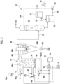
- the exhaust gas treatment facility in the present embodiment includes a dust collection filter device 10, an exhaust gas line 2, a treated exhaust gas line 2t, a stack 3, a suction blower 4, an exhaust heat recovery device 5, a reactant supplier 20, an acid gas separation device 30, and a regeneration device 60.
- the dust collection filter device 10 includes a case 11, a dust collection filter 13 capable of collecting solids SS, a backwashing device 14, and a discharger 15.
- the case 11 is formed with an inlet 11i through which gas flows in and an outlet 11o through which gas flows out.
- the dust collection filter 13 has heat resistance of 250°C or higher.
- the fibers constituting the dust collection filter 13 are, for example, glass fibers, ceramic fibers, or the like.
- the dust collection filter 13 is disposed so as to partition the inside of the case 11 into an inlet-side space 12i on the side of the inlet 11i and an outlet-side space 12o on the side of the outlet 11o.
- the backwashing device 14 can separate the solids SS collected by the dust collection filter 13 from the dust collection filter 13 by sending high-pressure gas (for example, high-pressure air) to the outlet-side space 12o so that the outlet-side space 12o in the case 11 has a higher pressure than the inlet-side space 12i.
- the backwashing device 14 includes a high-pressure gas tank for backwashing 14a, a high-pressure gas guide pipe 14b that sends the high-pressure gas in the high-pressure gas tank for backwashing 14a from the outlet-side space 12o side in the case 11 to the dust collection filter 13, and an on/off valve 14c provided in the high-pressure gas guide pipe 14b.
- the discharger 15 can discharge, to the outside, the solids SS that have been separated from the dust collection filter 13 by the operation of the backwashing device 14 and fall through the inlet-side space 12i in the case 11.
- Examples of the discharger 15 include a rotary valve and a screw conveyor.
- One end of the exhaust gas line 2 is connected to the exhaust gas generation source 1, and the other end of the exhaust gas line 2 is connected to an inlet 11i of the dust collection filter device 10. Therefore, the exhaust gas EG from the exhaust gas generation source 1 can be guided into the dust collection filter device 10 by the exhaust gas line 2.
- One end of the treated exhaust gas line 2t is connected to the outlet 11o of the dust collection filter device 10, and the other end of the treated exhaust gas line 2t is connected to the stack 3. Therefore, the treated exhaust gas EGt, which is the exhaust gas EG having passed through the dust collection filter device 10, can be guided to the stack 3 by the treated exhaust gas line 2t.
- the suction blower 4 and the exhaust heat recovery device 5 are provided in the treated exhaust gas line 2t.
- the exhaust heat recovery device 5 is a heat exchanger that heats the heating medium by exchanging heat between the treated exhaust gas EGt flowing through the treated exhaust gas line 2t and the heating medium. If the treated exhaust gas EGt can be discharged from the stack 3 without the suction blower 4, the suction blower 4 is unnecessary.
- the reactant supplier 20 can supply the reactant RS capable of reacting with the acid gas containing carbon dioxide into the exhaust gas EG.
- the reactant RS in the present embodiment is calcium hydroxide (Ca(OH) 2 , slaked lime) which is a kind of hydroxide (metal hydroxide or basic hydroxide).
- the reactant RS can react not only with carbon dioxide (CO 2 ) but also with sulfur dioxide (SO 2 ) and hydrochloric acid (HCl).
- the configuration of the reactant supplier 20 will be described later.
- the acid gas separation device 30 includes a heating device 31 capable of heating the solid SS from the dust collection filter device 10, a preheater (exhaust heat utilization device) 36, and a carbon dioxide separation device 51 capable of separating carbon dioxide from the gas discharged from the heating device 31.
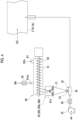
- the heating device 31 shown in Fig. 2 is a rotary kiln.
- the heating device 31 includes a barrel 32, an electric heater 33 disposed on the outer periphery of the barrel 32, a barrel rotation mechanism 34 that rotates the barrel 32, and a feeder 35 that feeds the solid SS into the barrel 32.
- a feeder 35 is connected to one end of the barrel 32, and a gas exhaust port 32g and a solid discharge port 32s are formed at the other end of the barrel 32.
- the solid SS discharged from the dust collection filter device 10 is supplied to the feeder 35.
- the solid SS contains a reaction product generated by the reaction between the acid gas and the reactant RS, the unreacted reactant RS, ash, heavy metals, and the like.
- the reaction products include calcium carbonate (CaCO 3 ) generated by the reaction between the reactant RS (Ca(OH) 2 ) and carbon dioxide (CO 2 ), calcium sulfate (CaSO 4 ) generated by the reaction between the reactant RS (Ca(OH) 2 ) and sulfur dioxide (SO 2 ), and calcium chloride (CaCl 2 ) generated by the reaction between the reactant RS (Ca(OH) 2 ) and hydrochloric acid (HCl).
- the reaction product may contain sulfides other than calcium sulfate and chlorides other than calcium chloride.
- the preheater 36 is disposed around the feeder 35 so as to be in contact with the feeder 35.
- the preheater (exhaust heat utilization device) 36 heats the solid SS by exchanging heat between the heating medium heated by the exhaust heat recovery device 5 and the solid SS in the feeder 35.
- the preheater 36 is disposed around the feeder 35, but the preheater 36 may be disposed around a pipe for feeding the solid SS from the dust collection filter device 10 to the heating device 31.
- the solid SS heated by the preheater 36 is fed into the barrel 32 by the feeder 35, and is further heated by the electric heater 33 in the barrel 32.
- the solid SS is heated to about 900°C by the electric heater 33.
- calcium carbonate (CaCO 3 ) in the solid SS is separated into calcium oxide (CaO, quicklime) and carbon dioxide (CO 2 ) as described below.
- Calcium sulfides such as calcium sulfate (CaSO 4 ) in the solid SS is separated into calcium oxide (CaO, quicklime), sulfur dioxide (SO 2 ), and oxygen (O 2 ).
- Calcium chlorides such as calcium chloride (CaCl 2 ) in the solid SS is separated into calcium oxide (CaO, quicklime) and hydrochloric acid (HCl).
- HCl hydrochloric acid
- the heated solid SSh generated by heating the solid SS in the barrel 32 is discharged from the solid discharge port 32s of the barrel 32.
- the heated solid SSh contains calcium oxide (CaO, quicklime), which is a kind of basic oxide (basic metal oxide).
- the gas generated by heating the solid SS in the barrel 32 is exhausted from the gas exhaust port 32g of the barrel 32.
- This gas contains carbon dioxide (CO 2 ), sulfur dioxide (SO 2 ), and hydrochloric acid (HCl).
- the heating device 31 heats the solid SS with an electric heater 33.
- a burner for injecting fuel into the barrel 32 may be provided, and the solid may be heated by heat generated by combustion of the fuel from the burner.
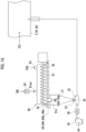
- the carbon dioxide separation device 51 includes an absorption tower 52, an absorption liquid tank 53, a circulation line 54, a liquid discharge line 55, a circulation pump 56, an undiluted absorption liquid tank 57, and an undiluted absorption liquid pump 58.
- the undiluted absorption liquid tank 57 stores an undiluted absorption liquid that absorbs sulfur dioxide (SO 2 ) and hydrochloric acid (HCl) and hardly absorbs carbon dioxide (CO 2 ). Examples of the absorption liquid include water at a predetermined temperature.
- the undiluted absorption liquid in the undiluted absorption liquid tank 57 is supplied into the absorption liquid tank 53 by the undiluted absorption liquid pump 58.
- a packing is disposed in an intermediate portion of the absorption tower 52.
- One end of an acid gas line 59 is connected to a portion below the packing of the absorption tower 52.
- the other end of the acid gas line 59 is connected to the gas exhaust port 32g of the barrel 32. Therefore, the acid gas from the heating device 31 flows into the absorption tower 52 through the acid gas line 59.
- One end of the circulation line 54 is connected to the lower end of the absorption tower 52, and the other end of the circulation line 54 is connected to a portion above the packing of the absorption tower 52.
- An absorption liquid tank 53 and a circulation pump 56 are connected to the circulation line 54. Therefore, the absorption liquid in the absorption liquid tank 53 is supplied to the upper portion of the absorption tower 52 through the circulation line 54.
- the absorption liquid in the absorption tower 52 returns to the absorption liquid tank 53 through the circulation line 54.
- a liquid discharge line 55 is connected to the circulation line 54.
- the absorption liquid is discharged to the outside through the circulation line 54 and the liquid discharge line 55 and is recovered.
- Carbon dioxide (CO 2 ) which is an acid gas that has not been absorbed by the absorption liquid in the absorption tower 52, is exhausted from the top of the absorption tower 52 to the outside and recovered.
- the acid gas separation device 30a of another aspect includes a heating device 31a capable of heating the solid SS from the dust collection filter device 10, a preheater 49, an air heater (exhaust heat utilization device) 47, and a carbon dioxide separation device 51 capable of separating carbon dioxide from the gas exhausted from the heating device 31a.
- the carbon dioxide separation device 51 of the acid gas separation device 30a is the same as the carbon dioxide separation device 51 of the acid gas separation device 30 described above.
- the heating device 31a of the acid gas separation device 30a is different from the heating device 31 of the acid gas separation device 30 described above.
- the heating device 31a shown in Fig. 3 includes a firing furnace 41 and a cyclone 48.
- the firing furnace 41 includes a furnace frame 42, a feeder 43 that feeds the solid SS into the furnace frame 42, a diffusion plate 44 in which a plurality of holes are formed, a carrier gas blower 45, a lower burner 46d, and an upper burner 46u.
- the space in the furnace frame 42 is partitioned by the diffusion plate 44 into an upper heating space 42hs and a lower carrier gas space 42cs.
- the lower burner 46d is connected to a lower portion of the furnace frame 42 so as to inject the fuel F and air into the carrier gas space 42cs.
- the upper burner 46u is connected to the upper portion of the furnace frame 42 so that the fuel F and air can be injected to the upper portion of the heating space 42hs.
- the feeder 43 is connected to an intermediate portion of the furnace frame 42 so as to be capable of supplying the solid SS from the dust collection filter device 10 to a lower portion of the heating space 42hs.
- the preheater 49 is disposed around the feeder 43 so as to be in contact with the feeder 43.
- the preheater 49 heats the solid SS by exchanging heat between the heating medium heated by the exhaust heat recovery device 5 and the solid portion in the feeder 43.
- the preheater 49 is disposed around the feeder 43, but the preheater 49 may be disposed around a pipe for feeding the solid SS from the dust collection filter device 10 to the heating device 31a.
- the carrier gas blower 45 sends air into the carrier gas space 42cs.
- the air heater (exhaust heat utilization device) 47 exchanges heat between the heating medium heated by the exhaust heat recovery device 5 and the air from the carrier gas blower 45 to heat the air. A part of the air is sent to the carrier gas space 42cs, and the remaining part is sent to the lower burner 46d and the upper burner 46u.
- the cyclone 48 includes a cyclone body 48b, a gas outlet pipe 48p, and a discharger 48e.
- the cyclone body 48b has a conical shape, and is disposed such that a portion corresponding to a bottom surface of the cone faces upward.
- the gas outlet pipe 48p is disposed on a central axis of the conical cyclone body 48b so as to penetrate from the upper side of the cyclone body 48b into the cyclone body 48b.
- the discharger 48e is connected to a lower portion of the cyclone body 48b.
- An inlet 48i is formed in a side periphery of an upper portion of the cyclone body 48b.
- the solids SS supplied from the dust collection filter device 10 to the feeder 43 are heated by the preheater 49 and then supplied to the lower portion of the heating space 42hs.
- Combustion gas is generated by combustion of the fuel F ejected from the lower burner 46d and the upper burner 46u.
- the solid SS is heated to about 900°C in the furnace frame 42 by the combustion gas.
- the firing furnace 41 includes a lower burner 46d and an upper burner 46u. However, the combustion furnace may have only one of the burners.
- the space in the furnace frame 42 is heated by combustion of fuel injected from a burner.
- an electric heater may be provided in the furnace frame 42, and the space in the furnace frame 42 may be heated by the electric heater.
- the solid SS When the solid SS is heated, as described above, the solid SS is decomposed, and the heated solid SSh and the acid gas are generated. Further, when the heat of the combustion gas generated by the combustion of the fuel is used to heat the solid SS, a combustion gas containing carbon dioxide is also generated.
- the heated solid SSh and the acid gas flow into the cyclone body 48b from the inlet 48i of the cyclone body 48b.
- the combustion gas also flows into the cyclone body 48b.
- the heated solid SSh which is a solid, and gas (acid gas, combustion gas) are separated.
- the heated solid SSh is discharged to the outside of the cyclone body 48b by the discharger 48e.
- the gas (acid gas, combustion gas) is sent to the absorption tower 52 of the carbon dioxide separation device 51 via the acid gas line 59.
- the carbon dioxide in the gas (acid gas, combustion gas) is separated from other gases in the gas in the absorption tower 52 and then recovered as described above.
- a cyclone is used for separation of the heated solid SSh and the gas, but a dust collection filter or a fluidized bed may be used instead of the cyclone.
- the heating device may have any configuration as long as the solid SS recovered from the dust collection filter device 10 can be heated to about 900°C or higher.
- the carbon dioxide separation device 51 may have any configuration as long as carbon dioxide can be separated from the acid gas.
- the acid gas separation devices 30 and 30a in the present embodiment include the carbon dioxide separation device 51 capable of separating carbon dioxide from the acid gas. However, when the acid gas can be recovered as it is, the carbon dioxide separation device 51 may be omitted.
- the regeneration device 60 includes a reaction container 61 and a stirrer 62 that stirs the inside of the reaction container 61.
- the reaction container 61 has an inlet 61i for guiding the heated solid SSh from the acid gas separation devices 30 and 30a into the inside, a water inlet 61sm for guiding water or steam SM into the inside, and a discharge port 61o for discharging a product generated by a reaction between the heated solid SSh and the water or steam SM.
- the regeneration device 60 may further include a heater 63 for heating the water or steam SM to be introduced into the reaction container 61.
- CaO calcium oxide
- quicklime which is a main component of the heated solid SSh, reacts with water or steam to generate calcium hydroxide (Ca (OH) 2 , slaked lime).
- the reactant supplier 20 includes a storage portion 21 capable of storing the reactant RS and a supply portion 22 capable of supplying the reactant RS stored in the storage portion 21 into the exhaust gas EG.
- the storage portion 21 is a reactant hopper capable of storing the reactant RS.
- the supply portion 22 includes a quantitative supplier 23, a transport line 24, an air conveyor blower 25, and an air heater 26. One end of the transport line 24 is connected to a discharge port of the air conveyor blower 25, and the other end of the transport line 24 is connected to the exhaust gas line 2.
- the quantitative supplier 23 is provided at a lower portion of the storage portion 21. The quantitative supplier 23 quantitatively supplies the reactant RS from the storage portion 21 into the transport line 24.
- an air heater 26 is provided between a discharge port of the air conveyor blower 25 and a position to which the reactant RS is supplied from the quantitative supplier 23.
- the air heater 26 heats the air from the air conveyor blower 25.
- the reactant RS supplied from the quantitative supplier 23 to the transport line 24 is transported in the transport line 24 by the air heated by the air heater 26 and supplied into the exhaust gas line 2.
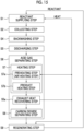
- the reactant supplier 20 supplies the reactant RS to the exhaust gas EG flowing through the exhaust gas line 2 (S1: reactant supplying step).
- the exhaust gas EG has a temperature of 250°C or more, for example, about 300 to 600°C.
- the exhaust gas EG contains acid gas, ash, heavy metals, and the like.
- the exhaust gas EG containing the reactant RS flows into the inlet-side space 12i of the dust collection filter device 10 through the exhaust gas line 2.
- the solid SS in the exhaust gas EG is collected by the dust collection filter 13, and the gas in the exhaust gas EG flows out of the dust collection filter device 10 as the treated exhaust gas EGt (S2: collecting step).
- the acid gas (including CO 2 , SO 2 , and HCl) in the exhaust gas EG reacts with the reactant RS to generate a reaction product in the process of passing through the exhaust gas line 2, the inlet-side space 12i of the dust collection filter device 10, and the layer of solid adhering to the dust collection filter 13.
- the reaction product adheres to the surface of the dust collection filter 13 as a part of the solid SS.
- the reaction product includes calcium carbonate (CaCO 3 ) generated by the reaction of carbon dioxide (CO 2 ), calcium sulfides generated by the reaction of sulfur dioxide (SO 2 ), calcium chlorides generated by the reaction of hydrochloric acid (HCl), and the like.
- Examples of the solid SS adhering to the surface of the dust collection filter 13 include ash, heavy metals, and the like in addition to the above reaction products.
- the treated exhaust gas EGt is exhausted from the stack 3 to the outside through the treated exhaust gas line 2t and the exhaust heat recovery device 5.
- the exhaust heat recovery device 5 heats the heating medium by exchanging heat between the treated exhaust gas EGt and the heating medium (S3: exhaust heat recovering step).
- the backwashing step S4 is performed.
- the on/off valve 14c of the backwashing device 14 is opened, and the high-pressure gas in the high-pressure gas tank for backwashing 14a is sent from the outlet-side space 12o side of the dust collection filter device 10 to the dust collection filter 13.
- the solids SS adhering to the dust collection filter 13 are peeled off from the dust collection filter 13 by the high-pressure gas, and the solids SS fall in the inlet-side space 12i of the dust collection filter device 10.
- the solids SS falling in the inlet-side space 12i are discharged to the outside of the dust collection filter device 10 by the discharger 15 (S5: discharging step).
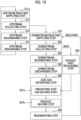
- the solid SS discharged from the dust collection filter device 10 enters the acid gas separation devices 30 and 30a, and the acid gas separating step S6 is performed by the acid gas separation devices 30 and 30a.
- the acid gas separating step S6 a heating step S7 and a carbon dioxide separating step S8 are performed.
- the acid gas separation device 30 includes the heating device 31 and the preheater 36
- the solid SS from the dust collection filter device 10 is supplied to the feeder 35 of the heating device 31.
- the preheater 36 heats the solid SS by exchanging heat between the heating medium heated by the exhaust heat recovery device 5 and the solid SS in the feeder 35 (S7a: preheating step).
- the preheating step S7a since the heat of the heating medium heated by the exhaust heat recovery device 5 is used, the preheating step S7a is also an exhaust heat utilizing step.
- the solid SS heated by the preheater 36 is fed into the barrel 32 by the feeder 35, and is further heated by the electric heater 33 in the barrel 32.
- the solid SS is heated to about 900°C by the electric heater 33 (S7b: product heating step).
- the acid gas separation device 30a includes the heating device 31a, the preheater (exhaust heat utilization device) 49, and the air heater (exhaust heat utilization device) 47
- the solid SS from the dust collection filter device 10 is supplied to the feeder 43 of the heating device 31a.
- the preheater (exhaust heat utilization device) 49 heats the solid SS by exchanging heat between the heating medium heated by the exhaust heat recovery device 5 and the solid SS in the feeder 43.
- the air heater (exhaust heat utilization device) 47 exchanges heat between the heating medium heated by the exhaust heat recovery device 5 and the air from the carrier gas blower 45 to heat the air (S7a: preheating step, air heating step).
- the preheating step and the air heating step S7a are also an exhaust heat utilizing step.
- the solid SS heated by the preheater 49 is supplied into the heating space 42hs of the heating device 31a by the feeder 43.
- the lower burner 46d injects the air heated by the air heater 47 and the fuel F into the carrier gas space 42cs.
- the fuel F burns in the carrier gas space 42cs.
- the combustion gas generated by the combustion of the fuel F and the air heated by the air heater 47 flow as a high-temperature carrier gas from the carrier gas space 42cs into the heating space 42hs via the diffusion plate 44.
- the solid SS from the feeder 43 is conveyed upward while being heated in the heating space 42hs by the carrier gas.
- the upper burner 46u injects the air heated by the air heater 47 and the fuel F to the upper portion of the heating space 42hs.
- the combustion gas generated by the combustion of the fuel F further heats the solid SS conveyed by the carrier gas.
- the solid SS is heated to about 900°C in the furnace frame 42 (S7b: product heating step).
- the reaction product in the solid SS is decomposed, and the heated solid SSh and the acid gas are generated.
- calcium carbonate (CaCO 3 ) in the reaction product is separated into calcium oxide (CaO, quicklime) and carbon dioxide (CO 2 ).
- the calcium sulfides in the reaction product is separated into calcium oxide (CaO, quicklime), sulfur dioxide (SO 2 ), and oxygen (O 2 ).
- the calcium chlorides in the reaction product is separated into calcium oxide (CaO, quicklime) and hydrochloric acid (HCl).
- the heated solid SSh contains ash and heavy metals in addition to the calcium oxide (CaO, quicklime) described above. Calcium oxide is a main component of the heated solid SSh. On the other hand, ash and heavy metals are trace components in the heated solid SSh.
- the acid gas contains carbon dioxide (CO 2 ), sulfur dioxide (SO 2 ), and hydrochloric acid (HCl). That is, the acid gas includes the acid gas in the exhaust gas EG.
- the heated solid SSh is sent from the heating devices 31 and 31a to the regeneration device 60.
- the acid gas is sent from the heating devices 31 and 31a to the carbon dioxide separation device 51.
- sulfur dioxide (SO 2 ) and hydrochloric acid (HCl) are absorbed by the absorption liquid and recovered.
- carbon dioxide (CO 2 ) in the acid gas sent to the carbon dioxide separation device 51 is not absorbed by the absorption liquid, and is exhausted to the outside and recovered.
- the combustion gas is also sent from the heating devices 31 and 31a to the carbon dioxide separation device 51 as described above.
- carbon dioxide contained in the combustion gas is also exhausted to the outside as a recovery target (S8: carbon dioxide separating step).
- the heated solid SSh containing calcium oxide is sent from the heating devices 31 and 31a of the acid gas separation devices 30 and 30a to the regeneration device 60.
- the regeneration device 60 supplies water or steam to the heated solid SSh.
- Calcium oxide (CaO, quicklime) which is a main component of the heated solid SSh, reacts with water or steam to become calcium hydroxide (Ca(OH) 2 , slaked lime) as described above (S9: regenerating step).
- Calcium hydroxide (Ca(OH) 2 , slaked lime) is the reactant RS in the present embodiment.
- a product containing calcium hydroxide (Ca(OH) 2 , slaked lime) as a main component, which is the reactant RS, is sent from the regeneration device 60 to the storage portion 21 of the reactant supplier 20.
- the supply portion 22 of the reactant supplier 20 pneumatically conveys a product containing the reactant RS stored in the storage portion 21 as a main component into the exhaust gas EG flowing through the exhaust gas line 2. That is, as described above, the reactant supplier 20 supplies the reactant RS to the exhaust gas EG flowing through the exhaust gas line 2 (S1: reactant supplying step).
- the acid gas (including carbon dioxide) in the exhaust gas EG reacts with the reactant RS to form a reaction product.
- the reaction product is collected by the dust collection filter 13 of the dust collection filter device 10 as a solid SS together with fine powder such as ash and heavy metals contained in the exhaust gas. Therefore, in the present embodiment, the acid gas (including carbon dioxide) in the exhaust gas EG can be removed together with the fine powder in the exhaust gas EG.
- the reaction environment be 250°C or higher.
- the dust collection filter 13 having heat resistance of 250°C or higher since the dust collection filter 13 having heat resistance of 250°C or higher is used, the exhaust gas EG having a temperature of 250°C or higher can flow into the dust collection filter device 10. That is, in the present embodiment, the reaction environment between the carbon dioxide in the exhaust gas EG and the reactant RS can be set to 250°C or higher. Therefore, in the present aspect, the removal efficiency of carbon dioxide from the exhaust gas EG can be increased.
- the space in which the reactant RS and the acid gas in the exhaust gas EG can react is the inside of the exhaust gas line 2 and the inlet-side space 12i of the dust collection filter device 10. For this reason, in the present embodiment, the space in which the reaction can be performed becomes wider than in a case where the reactant RS is directly supplied to the inlet-side space 12i of the dust collection filter device 10, and the reaction efficiency between the reactant RS and the acid gas in the exhaust gas EG can be increased.
- the solid SS as the reaction product generated by the reaction between the carbon dioxide in the exhaust gas EG and the reactant RS can be discharged from the dust collection filter device 10, and calcium hydroxide as the reactant RS can be regenerated from the reaction product. Therefore, in the present embodiment, the consumption amount of calcium hydroxide as the reactant RS can be suppressed.
- the reactant RS when the reactant RS is regenerated and repeatedly used, the reactant gradually deteriorates. For this reason, it is preferable to discharge from the regenerating cycle of the reactant RS a portion of the substance generated during this regenerating cycle while charging new substance into the regenerating cycle. Specifically, as shown in Fig. 1 , a part of the heated solid SSh from the acid gas separation device 30 (30a) is discharged, and calcium carbonate (CaCO 3 ) is charged into the acid gas separation device 30 (30a).
- CaCO 3 calcium carbonate
- calcium hydroxide which is a kind of hydroxide (metal hydroxide or basic hydroxide)
- a hydroxide metal hydroxide or basic hydroxide
- magnesium hydroxide Mg(OH) 2
- barium hydroxide Ba(OH) 2
- the main component in the heated solid SSh is calcium oxide (CaO, quicklime), which is a kind of basic oxide (basic metal oxide), as described above.
- the main component in the heated solid SSh is magnesium oxide (MgO) or barium oxide (BaO), which is another type of basic oxide (basic metal oxide).
- the hydroxide described above may not be used as the reactant RS.
- examples of the reactant RS capable of reacting with the acid gas include the following substances.
- the bicarbonates and carbonates react with sulfur dioxide and hydrochloric acid, which are a kind of acid gas, rather than with carbon dioxide, which is a kind of acid gas.
- the basic hydroxide can react with carbon dioxide, sulfur dioxide, and hydrochloric acid. Therefore, when the main purpose is to remove carbon dioxide in the exhaust gas EG, a hydroxide (metal hydroxide or basic hydroxide) is often used as the reactant RS.
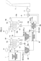
- the exhaust gas treatment facility in the present embodiment includes an upstream dust collection filter device 10f, an upstream exhaust gas line 2f, a downstream dust collection filter device 10b, a downstream exhaust gas line 2b, a treated exhaust gas line 2t, a stack 3, a suction blower 4, an exhaust heat recovery device 5, an upstream reactant supplier 20f, a downstream reactant supplier 20b, an acid gas separation device 30b, and a regeneration device 60.
- the upstream exhaust gas EGf which is the exhaust gas EG from the exhaust gas generation source 1, can be guided into the upstream dust collection filter device 10f by the upstream exhaust gas line 2f.
- downstream exhaust gas line 2b One end of the downstream exhaust gas line 2b is connected to the outlet 11o of the upstream dust collection filter device 10f, and the other end of the downstream exhaust gas line 2b is connected to the inlet 11i of the downstream dust collection filter device 10b. Therefore, the downstream exhaust gas EGb, which is the exhaust gas EG having passed through the upstream dust collection filter device 10f, can be guided into the downstream dust collection filter device 10b by the downstream exhaust gas line 2b.
- the upstream reactant supplier 20f and the downstream reactant supplier 20b have the same configuration as the reactant supplier 20 in the first embodiment. Therefore, as shown in Fig. 4 , the upstream reactant supplier 20f has a storage portion 21 capable of storing the upstream reactant RSf and a supply portion 22 capable of supplying the upstream reactant RSf stored in the storage portion 21 into the upstream exhaust gas EGf. Further, the downstream reactant supplier 20b has a storage portion 21 capable of storing the downstream reactant RSb and a supply portion 22 capable of supplying the downstream reactant RSb stored in the storage portion 21 into the downstream exhaust gas EGb.
- Each of the supply portion 22 of the upstream reactant supplier 20f and the supply portion 22 of the downstream reactant supplier 20b includes a quantitative supplier 23, a transport line 24, an air conveyor blower 25, and an air heater 26.
- One end of the transport line 24 of the upstream reactant supplier 20f is connected to the discharge port of the air conveyor blower 25 of the upstream reactant supplier 20f, and the other end of the transport line 24 is connected to the upstream exhaust gas line 2f.
- One end of the transport line 24 of the downstream reactant supplier 20b is connected to the discharge port of the air conveyor blower 25 of the downstream reactant supplier 20b, and the other end of the transport line 24 is connected to the downstream exhaust gas line 2b.
- the upstream reactant RSf and the downstream reactant RSb are both calcium hydroxide (Ca(OH) 2 , slaked lime), which is the same as the reactant RS in the first embodiment. Therefore, for example, the storage portion 21 of the upstream reactant supplier 20f and the storage portion 21 of the downstream reactant supplier 20b may be shared by the upstream reactant supplier 20f and the downstream reactant supplier 20b. As described above, hydroxides (metal hydroxides or basic hydroxides) other than calcium hydroxide (Ca(OH) 2 , slaked lime) may be used as the upstream reactant RSf and the downstream reactant RSb.
- the quantitative supplier 23, the air conveyor blower 25, and the air heater 26 of the upstream reactant supplier 20f and the quantitative supplier 23, the air conveyor blower 25, and the air heater 26 of the downstream reactant supplier 20b may be shared by the upstream reactant supplier 20f and the downstream reactant supplier 20b.
- the acid gas separation device 30b includes heating devices 31 and 31a having the same configuration as the heating devices 31 and 31a of the acid gas separation devices 30 and 30a in the first embodiment. However, the acid gas separation device 30b does not have the carbon dioxide separation device 51 of the acid gas separation devices 30 and 30a in the first embodiment.
- the acid gas separation device 30b can separate the acid gas from the solid SS from the downstream dust collection filter device 10b.
- the regeneration device 60 has the same configuration as the regeneration device 60 in the first embodiment. However, the regeneration device 60 in the present embodiment can send the substance containing calcium hydroxide as a main component regenerated by the regeneration device 60 to the upstream reactant supplier 20f and the downstream reactant supplier 20b.
- the acid gas (including CO 2 , SO 2 , and HCl) in the upstream exhaust gas EGf reacts with the upstream reactant RSf to generate an upstream reaction product in the process of passing through the upstream exhaust gas line 2f, the inlet-side space 12i of the upstream dust collection filter device 10f, and the layer of the solid adhering to the dust collection filter 13.
- the upstream reaction product adheres to the surface of the dust collection filter 13 as a part of the solid SSf.
- the upstream reaction product includes calcium carbonate (CaCO 3 ) generated by the reaction of carbon dioxide (CO 2 ), calcium sulfides generated by the reaction of sulfur dioxide (SO 2 ), and calcium chlorides generated by the reaction of hydrochloric acid (HCl).
- Examples of the solid SSf adhering to the surface of the dust collection filter 13 include ash, heavy metals, and the like in addition to the above reaction products.
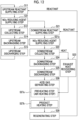
- the upstream reactant supplier 20f supplies the upstream reactant RSf to the upstream exhaust gas EGf flowing through the upstream exhaust gas line 2f (S11: upstream reactant supplying step).
- the upstream exhaust gas EGf containing the upstream reactant RSf flows into the inlet-side space 12i of the upstream dust collection filter device 10f through the upstream exhaust gas line 2f.
- the solid SSf in the upstream exhaust gas EGf is collected by the dust collection filter 13, and the gas in the upstream exhaust gas EGf flows out from the upstream dust collection filter device 10f as the downstream exhaust gas EGb (S12: upstream collecting step).
- the downstream exhaust gas EGb contains carbon dioxide (CO 2 ), but hardly contains sulfur disulfide (SO 2 ) and hydrochloric acid (HCl).
- SO 2 sulfur disulfide
- HCl hydrochloric acid
- the upstream backwashing step S14 is performed.
- the solid SSf adhering to the dust collection filter 13 of the upstream dust collection filter device 10f is peeled off from the dust collection filter 13, and the solid SSf falls in the inlet-side space 12i of the upstream dust collection filter device 10f.
- the solid SSf falling in the inlet-side space 12i is discharged to the outside of the upstream dust collection filter device 10f by the discharger 15 and recovered (S15: upstream discharging step).
- the solid SSf discharged from the upstream dust collection filter device 10f contains ash, heavy metals, and the like in addition to calcium carbonate (CaCO 3 ), calcium sulfides, and calcium chlorides.
- the downstream reactant supplier 20b supplies the downstream reactant RSb to the downstream exhaust gas EGb flowing through the downstream exhaust gas line 2b (S21: downstream reactant supplying step).
- the downstream exhaust gas EGb containing the downstream reactant RSb flows into the inlet-side space 12i of the downstream dust collection filter device 10b through the downstream exhaust gas line 2b.
- the solid SSb in the downstream exhaust gas EGb is collected by the dust collection filter 13, and the gas in the downstream exhaust gas EGb flows out from the downstream dust collection filter device 10b as the treated exhaust gas EGt (S22: downstream collecting step).
- the carbon dioxide (CO 2 ) in the downstream exhaust gas EGb reacts with the downstream reactant RSb to generate a reaction product in the process of passing through the downstream exhaust gas line 2b, the inlet-side space 12i of the downstream dust collection filter device 10b, and the layer of solid adhering to the dust collection filter 13.
- the reaction product adheres to the surface of the dust collection filter 13 as a part of the solid SSb.
- the reaction product is calcium carbonate (CaCO 3 ) generated by the reaction of carbon dioxide (CO 2 ).
- sulfur disulfide (SO 2 ) and hydrochloric acid (HCl) are hardly contained in the downstream exhaust gas EGb. Therefore, the reaction efficiency between the downstream reactant RSb and carbon dioxide (CO 2 ) can be increased. Further, the reaction product hardly contains calcium sulfides generated by the reaction of sulfur dioxide (SO 2 ) and calcium chlorides generated by the reaction of hydrochloric acid (HCl).
- the treated exhaust gas EGt is exhausted from the stack 3 to the outside through the treated exhaust gas line 2t and the exhaust heat recovery device 5.
- the exhaust heat recovery device 5 heats the heating medium by exchanging heat between the treated exhaust gas EGt and the heating medium (S23: exhaust heat recovering step).
- the downstream backwashing step S24 is performed.
- the solid SSb adhering to the dust collection filter 13 of the downstream dust collection filter device 10b is peeled off from the dust collection filter 13, and the solid SSb falls in the inlet-side space 12i of the downstream dust collection filter device 10b.
- the solids SSb falling in the inlet-side space 12i are discharged to the outside of the downstream dust collection filter device 10b by the discharger 15 and recovered (S25: downstream discharging step).
- the solid SSb discharged from the downstream dust collection filter device 10b enters the acid gas separation device 30b, and the acid gas separating step S26 is performed by the acid gas separation device 30b.
- the acid gas separating step S26 similarly to the heating step S7 of the acid gas separating step S6 in the first embodiment, a preheating step, an air heating step (exhaust heat utilizing step) S27a, and a product heating step S27b are performed.
- the carbon dioxide separating step S8 of the acid gas separating step S6 in the first embodiment may not be performed.
- the acid gas generated by performing the product heating step S7b contains carbon dioxide (CO 2 ), sulfur dioxide (SO 2 ), and hydrochloric acid (HCl). Therefore, in the first embodiment, the carbon dioxide separating step S8 is performed in order to separate carbon dioxide (CO 2 ) from the acid gas.
- the reaction product in the solid SSb is decomposed, and the heated solid SSh and the acid gas are generated.
- the solid SSb discharged from the downstream dust collection filter device 10b contains calcium carbonate (CaCO 3 ), but hardly contains calcium sulfides, calcium chlorides, ash, heavy metals, and the like. Therefore, in the heated solid SSh in the present embodiment, calcium oxide (CaO) generated by thermal decomposition of calcium carbonate (CaCO 3 ) is a main component, and other components are trace amounts.
- the carbon dioxide separating step S8 in the first embodiment may not be performed. In other words, the carbon dioxide separating step S8 may be performed as necessary.
- the heated solid SSh containing calcium oxide (CaO) as a main component is sent from the acid gas separation device 30b to the regeneration device 60.
- the regeneration device 60 supplies water or steam to the heated solid SSh.
- Calcium oxide (CaO, quicklime) which is a main component of the heated solid SSh, reacts with water or steam to become calcium hydroxide (Ca(OH) 2 , slaked lime) as described above (S28: regenerating step).
- Calcium hydroxide (Ca(OH) 2 , slaked lime) is the upstream reactant RSf and the downstream reactant RSb in the present embodiment.
- a product containing calcium hydroxide (Ca(OH) 2 , slaked lime) as a main component, which is a reactant, is sent from the regeneration device 60 to the storage portion 21 of the upstream reactant supplier 20f and the storage portion 21 of the downstream reactant supplier 20b.
- the supply portion 22 of the upstream reactant supplier 20f pneumatically conveys a product containing the reactant RS stored in the storage portion 21 as a main component into the upstream exhaust gas EGf flowing through the upstream exhaust gas line 2f.
- the upstream reactant supplier 20f supplies the upstream reactant RSf to the upstream exhaust gas EGf flowing through the upstream exhaust gas line 2f (S11: upstream reactant supplying step).
- the supply portion 22 of the downstream reactant supplier 20b pneumatically conveys a product containing the reactant RS stored in the storage portion 21 as a main component into the downstream exhaust gas EGb flowing through the downstream exhaust gas line 2b. That is, the downstream reactant supplier 20b supplies the downstream reactant RSb to the downstream exhaust gas EGb flowing through the downstream exhaust gas line 2b (S21: downstream reactant supplying step).
- the reactant is supplied into the exhaust gas and the solid in the exhaust gas is collected by the dust collection filter devices 10f and 10b, it is possible to remove the acid gas (including carbon dioxide) in the exhaust gas together with the fine powder in the exhaust gas.
- the reactant is regenerated from the reaction product generated by the reaction with the reactant, the consumption amount of the reactant can be suppressed.
- the reactant is regenerated from the solid SSb that contains the reaction product and hardly contains heavy metals and the like, a high-purity reactant that does not contain heavy metals and the like can be supplied into the exhaust gas EG.
- carbon dioxide with high purity can be recovered without performing a complicated separating step.
- the exhaust gas treatment facility includes the two dust collection filter devices 10f and 10b in order to supply a high-purity reactant not containing heavy metals or the like into the exhaust gas.
- the size of each of the dust collection filter devices 10f and 10b can be made smaller than the size of the dust collection filter device 10 in the first embodiment.
- the main role of the upstream dust collection filter device 10f in the present embodiment is to collect calcium sulfides, calcium chlorides, ash, heavy metals, and the like.
- the main role of the downstream dust collection filter device 10b in the present embodiment is to collect calcium carbonate (CaCO 3 ).
- the carbon dioxide separating step S8 of the acid gas separating step S6 in the first embodiment can be omitted. Therefore, in the acid gas separation device 30b of the present embodiment, the carbon dioxide separation device 51 of the acid gas separation devices 30 and 30a in the first embodiment can be omitted. Therefore, in the present embodiment, although two dust collection filter devices 10 are provided, an increase in facility cost can be suppressed.
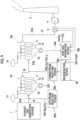
- the exhaust gas treatment facility in the present embodiment includes an upstream dust collection filter device 10f, an upstream exhaust gas line 2f, a downstream dust collection filter device 10b, a downstream exhaust gas line 2b, a treated exhaust gas line 2t, a stack 3, a suction blower 4, an exhaust heat recovery device 5, an upstream reactant supplier 20fa, a downstream reactant supplier 20b, an acid gas separation device 30b, and a regeneration device 60.
- the upstream reactant supplier 20f in the second embodiment supplies calcium hydroxide (Ca(OH) 2 , slaked lime) from the regeneration device 60 to the upstream exhaust gas line 2f as the upstream reactant RSf.
- the upstream reactant supplier 20fa in the present embodiment supplies the metal carbonate to the upstream exhaust gas line 2f.
- the exhaust gas treatment facility in the present embodiment is different from the exhaust gas treatment facility in the second embodiment only in this point.
- the upstream reactant supplier 20fa in the present embodiment has basically the same configuration as the upstream reactant supplier 20f in the second embodiment. Therefore, as shown in Fig. 4 , the upstream reactant supplier 20fa includes a storage portion 21 capable of storing the upstream reactant RSf, and a supply portion 22 capable of supplying the upstream reactant RSf stored in the storage portion 21 into the upstream exhaust gas EGf. However, the storage portion 21 of the upstream reactant supplier 20fa in the present embodiment stores the above-described metal carbonate as the upstream reactant RSf. For this reason, the supply portion 22 of the upstream reactant supplier 20fa in the present embodiment supplies the metal carbonate as the upstream reactant RSf into the upstream exhaust gas EGf. In Fig. 4 , the upstream reactant supplier 20fa is illustrated to receive the reactant from the regeneration device 60, but the upstream reactant supplier 20fa does not receive the reactant from the regeneration device 60.
- Examples of the metal carbonate used in the present embodiment include calcium carbonate (CaCO 3 ), sodium carbonate (Na 2 CO 3 ), magnesium carbonate (MgCO 3 ), barium carbonate (BaCO 3 ), potassium carbonate (K 2 CO 3 ), calcium hydrogen carbonate (Ca(HCO 3 ) 2 ), sodium hydrogen carbonate (sodium bicarbonate, baking soda) (NaHCO 3 ), magnesium hydrogen carbonate (Mg(HCO 3 ) 2 ), barium hydrogen carbonate (Ba (HCO 3 ) 2 ), and potassium hydrogen carbonate (KHCO 3 ).
- the upstream reactant supplier 20fa supplies the upstream reactant RSf to the upstream exhaust gas EGf flowing through the upstream exhaust gas line 2f (S11a: upstream reactant supplying step).
- the upstream exhaust gas EGf containing the upstream reactant RSf flows into the inlet-side space 12i of the upstream dust collection filter device 10f through the upstream exhaust gas line 2f.
- the solid SSf in the upstream exhaust gas EGf is collected by the dust collection filter 13, and the gas in the upstream exhaust gas EGf flows out from the upstream dust collection filter device 10f as the downstream exhaust gas EGb (S12: upstream collecting step).
- the acid gas (including CO 2 , SO 2 , and HCl) in the upstream exhaust gas EGf reacts with the upstream reactant RSf to generate an upstream reaction product in the process of passing through the upstream exhaust gas line 2f, the inlet-side space 12i of the upstream dust collection filter device 10f, and the layer of the solid adhering to the dust collection filter 13.
- the upstream reaction product adheres to the surface of the dust collection filter 13 as a part of the solid SSf. It is assumed that sodium hydrogen carbonate (sodium bicarbonate, baking soda) (NaHCO 3 ), which is a kind of metal carbonate, is used as the upstream reactant RSf.
- the upstream reaction product includes sodium sulfides such as sodium sulfate (Na 2 SO 4 ) and carbon dioxide (CO 2 ) generated by the reaction between the upstream reactant RSf (NaHCO 3 ) and sulfur dioxide (SO 2 ), and sodium chlorides such as sodium chloride (NaCl) and carbon dioxide (CO 2 ) generated by the reaction between the upstream reactant RSf (NaHCO 3 ) and hydrochloric acid (HCl).
- sodium sulfides such as sodium sulfate (Na 2 SO 4 ) and carbon dioxide (CO 2 ) generated by the reaction between the upstream reactant RSf (NaHCO 3 ) and sulfur dioxide (SO 2 )
- sodium chlorides such as sodium chloride (NaCl) and carbon dioxide (CO 2 ) generated by the reaction between the upstream reactant RSf (NaHCO 3 ) and hydrochloric acid (HCl).
- the carbon dioxide generated by this reaction is recovered as carbonate by the downstream dust collection
- Examples of the solid SSf adhering to the surface of the dust collection filter 13 of the upstream dust collection filter device 10f include ash, heavy metals, and the like in addition to sodium sulfides and sodium chlorides among the upstream reaction products described above.
- carbon dioxide (CO 2 ) which is a gas passes through the dust collection filter 13 of the upstream dust collection filter device 10f and flows out from the upstream dust collection filter device 10f to the downstream exhaust gas line 2b.
- the upstream backwashing step S14 and the upstream discharging step S15 are performed.
- downstream reactant supplier 20b supplies the downstream reactant RSb to the downstream exhaust gas EGb flowing through the downstream exhaust gas line 2b (S21: reactant supplying step).
- the downstream exhaust gas EGb containing the downstream reactant RSb flows into the inlet-side space 12i of the downstream dust collection filter device 10b through the downstream exhaust gas line 2b.
- the solid SSb in the downstream exhaust gas EGb is collected by the dust collection filter 13, and the gas in the downstream exhaust gas EGb flows out from the downstream dust collection filter device 10b as the treated exhaust gas EGt (S22: downstream collecting step).
- the carbon dioxide (CO 2 ) in the downstream exhaust gas EGb reacts with the downstream reactant RSb to generate a reaction product in the process of passing through the downstream exhaust gas line 2b, the inlet-side space 12i of the downstream dust collection filter device 10b, and the layer of solid adhering to the dust collection filter 13.
- the reaction product adheres to the surface of the dust collection filter 13 as a part of the solid SSb.
- the reaction product is calcium carbonate (CaCO 3 ) generated by the reaction of carbon dioxide (CO 2 ).
- sulfur disulfide (SO 2 ) and hydrochloric acid (HCl) are hardly contained in the downstream exhaust gas EGb. Therefore, the reaction efficiency between the downstream reactant RSb and carbon dioxide (CO 2 ) can be increased. Further, the reaction product hardly contains calcium sulfides generated by the reaction of sulfur dioxide (SO 2 ) and calcium chlorides generated by the reaction of hydrochloric acid (HCl).
- the exhaust heat recovering step S23, the downstream backwashing step S24, the downstream discharging step S25, the acid gas separating step S26, and the regenerating step S28 are performed.
- the reactant regenerated in the regenerating step S28 of the present embodiment is supplied only to the downstream reactant supplier 20b as the downstream reactant RSb.
- the reactant is supplied into the exhaust gas, and the solid in the exhaust gas is collected by the dust collection filter devices 10f and 10b, as in each of the above embodiments. Therefore, the acid gas (including carbon dioxide) in the exhaust gas EG can be removed together with the fine powder in the exhaust gas EG.
- the reactant is regenerated from the reaction product generated by the reaction with the reactant, the consumption amount of the reactant can be suppressed.
- the reactant is regenerated from the solid SSb that contains the reaction product and hardly contains heavy metals and the like, it is possible to supply a high-purity reactant that does not contain heavy metals and the like into the exhaust gas EG.
- carbon dioxide with high purity can be recovered without performing a complicated separating step.
- the exhaust gas treatment facility in the present embodiment also includes two dust collection filter devices 10 as in the second embodiment, but can suppress an increase in facility cost.
- the exhaust gas treatment facility in the present embodiment is a facility in which a NOx reducing agent supplier 70 is added to the exhaust gas treatment facility in the second embodiment.
- the NOx reducing agent supplier 70 can supply the NOx reducing agent into the upstream exhaust gas line 2f.
- a reduction catalyst 17 is supported on the dust collection filter 13 of the upstream dust collection filter device 10f.
- the reduction catalyst 17 includes a support and an active component.
- the support is, for example, a single oxide or a composite oxide containing at least one element selected from titanium, silicon, aluminum, zirconium, and cerium.
- the active component is, for example, a single oxide, a composite oxide, or an alloy containing at least one element selected from vanadium, tungsten, molybdenum, barium, potassium, platinum, copper, silver, rhodium, and palladium.
- the upstream reactant supplier 20f supplies the upstream reactant RSf to the upstream exhaust gas EGf flowing through the upstream exhaust gas line 2f (S11: upstream reactant supplying step). Further, the NOx reducing agent supplier 70 supplies the NOx reducing agent to the upstream exhaust gas EGf flowing through the upstream exhaust gas line 2f (S31: NOx reducing agent supplying step).
- the NOx reducing agent is, for example, a substance containing at least one of ammonia, hydrocarbon, carbon monoxide, and hydrogen.
- the upstream exhaust gas EGf containing the upstream reactant RSf and the NOx reducing agent flows into the inlet-side space 12i of the upstream dust collection filter device 10f through the upstream exhaust gas line 2f.
- the solid SSf in the upstream exhaust gas EGf is collected by the dust collection filter 13, and the gas in the upstream exhaust gas EGf flows out from the upstream dust collection filter device 10f as the downstream exhaust gas EGb (S12: upstream collecting step).
- nitrogen monoxide in the upstream exhaust gas EGf reacts with ammonia, which is the NOx reducing agent in the upstream exhaust gas EGf, in an environment in which the reduction catalyst 17 is present, and becomes nitrogen (N 2 ) and water (H 2 O), as shown below.
- ammonia which is the NOx reducing agent in the upstream exhaust gas EGf
- the upstream backwashing step S14, the upstream discharging step S15, the downstream reactant supplying step S21, the downstream collecting step S2, the exhaust heat recovering step S23, the downstream backwashing step S24, the downstream discharging step S25, the acid gas separating step S26, and the regenerating step S28 are performed.
- the exhaust gas treatment facility of the present embodiment includes all the configurations of the exhaust gas treatment facility of the second embodiment, the same effects as those of the second embodiment can be obtained.
- nitrogen monoxide in the upstream exhaust gas EGf can be removed.
- the NOx reducing agent is supplied to the upstream exhaust gas EGf in the upstream exhaust gas line 2f.
- the NOx reducing agent supplier 70 may supply the NOx reducing agent to the downstream exhaust gas EGb flowing through the downstream exhaust gas line 2b (S31a: NOx reducing agent supplying step).
- the present embodiment is a facility in which the NOx reducing agent supplier 70 is added to the exhaust gas treatment facility in the second embodiment.
- the NOx reducing agent supplier 70 may be added to the exhaust gas treatment facility in the first embodiment and the third embodiment.
- the preheaters 36 and 49 and the air heater 47 are exemplified as the exhaust heat utilization devices.
- other devices may be the exhaust heat utilization devices.
- the heater 63 or the air heater 26 illustrated in Fig. 4 may be an exhaust heat utilization device that uses the heating medium heated by the exhaust heat recovery device 5 as the heating medium. That is, any one of the reactant supplier 20, 20f, 20fa, and 20b, the acid gas separation devices 30, 30a, and 30b, and the regeneration device 60 may have the exhaust heat utilization device.
- any one of the reactant supplying step, the heating step, and the regenerating step may include the exhaust heat utilizing step.
- the exhaust heat recovery device 5 in the above embodiment is a heat exchanger that heats the heating medium by exchanging heat between the treated exhaust gas EGt flowing through the treated exhaust gas line 2t and the heating medium.
- the exhaust heat recovery devices 5g and 5s may be heat exchangers capable of heating the heating medium by exchanging heat between the gas generated by the heating device 31 of the acid gas separation device 30 and the heating medium.
- the exhaust heat recovery devices 5ga and 5sa may be heat exchangers capable of heating the heating medium by exchanging heat between the heated solid generated by the heating device 31a of the acid gas separation device 30a and the heating medium.
- the exhaust heat recovery devices 5g, 5ga, 5s, and 5sa are provided around the gas exhaust port or the solid discharge port in the heating devices 31 and 31a.
- the exhaust heat recovery devices 5g, 5ga, 5s, and 5sa heat the heating medium by exchanging heat between the heated solid or gas generated in the product heating step S7b and the heating medium (exhaust heat recovering step S5a).
- any one of the reactant supplier 20, 20f, 20fa, and 20b, the acid gas separation devices 30, 30a, and 30b, and the regeneration device 60 may have the exhaust heat utilization device as described above.
- any one of the reactant supplying step, the heating step, and the regenerating step may include the exhaust heat utilizing step.
- the exhaust heat recovery device 5b may be a heat exchanger capable of heating a heating medium by causing the heating medium to absorb a part of reaction heat generated when water or steam is supplied to the basic oxide in the regeneration device 60.
- the exhaust heat recovery device 5b is provided around the reaction container 61 or inside the reaction container 61 in the regeneration device 60.
- the exhaust heat recovery device 5b causes the heating medium to absorb a part of the reaction heat generated when water or steam is supplied to the basic oxide in the regenerating step S9, thereby heating the heating medium (exhaust heat recovering step S5b).
- any one of the reactant supplier 20, 20f, 20fa, and 20b, the acid gas separation devices 30, 30a, and 30b, and the regeneration device 60 may have the exhaust heat utilization device as described above.
- any one of the reactant supplying step, the heating step, and the regenerating step may include the exhaust heat utilizing step.
- the exhaust heat utilization device described above is one of the devices constituting the exhaust gas treatment facility.
- the exhaust heat utilization device may utilize the heat of the heating medium heated by the exhaust heat recovery device in another device or another facility other than the device constituting the exhaust gas treatment facility.
- the exhaust heat utilizing step of utilizing heat of the heating medium heated in the exhaust heat recovering step may be performed in a step other than the steps performed in the method for treating an exhaust gas.
- the heat of the heating medium heated by the exhaust heat recovery device may be used in a hot water supply facility or a power generation facility of a management building that manages the exhaust gas treatment facility.
- the exhaust gas treatment facility in the second to fourth embodiments described above includes one downstream dust collection filter device 10b.
- a plurality of downstream dust collection filter devices 10b may be provided.
- the reactant is supplied to the exhaust gas flowing into each of the downstream dust collection filter devices 10b.
- the exhaust gas treatment facility according to the above embodiment is understood as follows, for example.
- the carbon dioxide in the exhaust gas EG, EGb reacts with the reactant RS, RSb to form reaction products.
- the reaction products are collected by the dust collection filter 13 of the dust collection filter device 10 10b as solid SS, SSb together with fine powders such as ash and heavy metals contained in the exhaust gas. Therefore, in the present aspect, carbon dioxide in the exhaust gas EG, EGb can be removed together with the fine powder in the exhaust gas EG, EGb.
- the reaction environment be 250°C or higher.
- the dust collection filter 13 having heat resistance of 250°C or higher is used, the exhaust gas EG, EGb of 250°C or more can flow into the dust collection filter device 10, 10b. That is, in the present aspect, the reaction environment between the carbon dioxide in the exhaust gas EG, EGb and the reactant RS, RSb can be set to 250°C or higher. Therefore, in the present aspect, the removal efficiency of carbon dioxide from the exhaust gas EG, EGb can be increased.
- the reactant supplier 20, 20b is connected to the exhaust gas line 2, 2b and is capable of supplying the reactant RS, RSb into the exhaust gas line 2, 2b.
- the space in which the reactant RS, RSb can react is wider than in the case where the reactant RS, RSb are directly supplied to the inlet-side space 12i of the dust collection filter device 10, 10b, and the reaction efficiency between the reactant RS, RSb and the carbon dioxide in the exhaust gas EG, EGb can be increased.
- the exhaust gas treatment facility further includes, in the exhaust gas treatment facility according to the first aspect or the second aspect, an upstream dust collection filter device 10f in addition to a downstream dust collection filter device 10b as the dust collection filter device 10b, an upstream exhaust gas line 2f capable of introducing an upstream exhaust gas EGf containing an acid gas that contains carbon dioxide into the upstream dust collection filter device 10f, in addition to a downstream exhaust gas line 2b as the exhaust gas line 2b, and an upstream reactant supplier 20f capable of supplying an upstream reactant RSf capable of reacting with the acid gas into the upstream exhaust gas EGf, in addition to a downstream reactant supplier 20b as the reactant supplier 20b.
- the upstream dust collection filter device 10f includes a case 11 in which an inlet 11i through which a gas flows in and an outlet 11o through which a gas flows out are formed; and a dust collection filter 13 that partitions an inside of the case 11 of the upstream dust collection filter device 10f into an inlet-side space 12i on a side of the inlet 11i of the upstream dust collection filter device 10f and an outlet-side space 12o on a side of the outlet 11o of the upstream dust collection filter device 10f and has heat resistance of 250°C or higher.
- the upstream exhaust gas line 2f is connected to the inlet 11i of the upstream dust collection filter device 10f.
- the downstream exhaust gas line 2b is connected to the outlet 11o of the upstream dust collection filter device 10f and is connected to the inlet 11i of the downstream dust collection filter device 10b, and is capable of introducing downstream exhaust gas EGb as the exhaust gas EGb into the downstream dust collection filter device 10b.
- the upstream reactant supplier 20f can supply the upstream reactant RSf to the upstream exhaust gas line 2f and/or the inlet-side space 12i of the upstream dust collection filter device 10f.
- the upstream dust collection filter device 10f of the present aspect can collect ash and heavy metals in addition to the reaction product of the acid gas and the upstream reactant RSf in the upstream exhaust gas EGf.
- the downstream dust collection filter device 10b of the present aspect it is possible to exclusively collect the reaction product between the acid gas that has not reacted with the upstream reactant RSf among the acid gases in the upstream exhaust gas EGf and the downstream reactant RSb.
- the upstream reactant supplier 20f includes a storage portion 21 capable of storing a metal carbonate or a metal bicarbonate as the upstream reactant RSf, and a supply portion 22 capable of supplying the metal carbonate or the metal bicarbonate stored in the storage portion 21 to the upstream exhaust gas line 2f or the inlet-side space 12i of the upstream dust collection filter device 10f.
- sulfur dioxide and hydrochloric acid when sulfur dioxide and hydrochloric acid are contained as acid gases in the upstream exhaust gas EGf, these can be efficiently collected in the upstream dust collection filter device 10f in the form of reaction products. Further, in the present aspect, since sulfur dioxide and hydrochloric acid are hardly contained in the downstream exhaust gas EGb, the reaction efficiency between carbon dioxide in the downstream exhaust gas EGb and the downstream reactant RSb can be enhanced.
- the exhaust gas treatment facility according to a fifth aspect further includes, in the exhaust gas treatment facility according to the third aspect or the fourth aspect, a NOx reducing agent supplier 70 capable of supplying a NOx reducing agent into the upstream exhaust gas line 2f.
- a reduction catalyst 17 is attached to the dust collection filter 13 of the upstream dust collection filter device 10f.
- the upstream exhaust gas EGf when the upstream exhaust gas EGf contains nitrogen monoxide, the upstream exhaust gas EGf can be decomposed into nitrogen and water.
- the exhaust gas treatment facility further includes, in the exhaust gas treatment facility according to any one of the third aspect to the fifth aspect, a NOx reducing agent supplier 70 capable of supplying a NOx reducing agent into the downstream exhaust gas line 2b.
- a reduction catalyst 17 is attached to the dust collection filter 13 of the downstream dust collection filter device 10b.
- the downstream exhaust gas EGb when the downstream exhaust gas EGb contains nitrogen monoxide, the downstream exhaust gas EGb can be decomposed into nitrogen and water.
- the exhaust gas treatment facility according to a seventh aspect further includes, in the exhaust gas treatment facility according to any one of the first to fourth aspects, a NOx reducing agent supplier 70 capable of supplying a NOx reducing agent into the exhaust gas line 2b.
- a reduction catalyst 17 is attached to the dust collection filter 13 of the dust collection filter device 10b.
- the exhaust gas EG when the exhaust gas EG contains nitrogen monoxide, the exhaust gas EG can be decomposed into nitrogen and water.
- the reactant supplier 20, 20b includes a storage portion 21 capable of storing a hydroxide, a metal carbonate, a metal bicarbonate, or a metal oxide as the reactant RS, RSb, and a supply portion 22 capable of supplying the hydroxide, the metal carbonate, the metal bicarbonate, or the metal oxide stored in the storage portion 21 of the reactant supplier 20, 20b into the exhaust gas EG, EGb.
- the dust collection filter device 10, 10b includes a backwashing device 14 capable of separating a solid SS, SSb collected by the dust collection filter 13 from the dust collection filter 13 by sending high-pressure gas to the outlet-side space 12o so that the outlet-side space 12o has a higher pressure than the inlet-side space 12i, and a discharger 15 capable of discharging the solid SS, SSb in the inlet-side space 12i separated from the dust collection filter 13 to an outside.
- the solids SS, SSb collected by the dust collection filter 13 of the dust collection filter device 10, 10b can be discharged to the outside of the dust collection filter device 10, 10b.
- the reactant supplier 20, 20b includes a storage portion 21 capable of storing a hydroxide as the reactant RS, RSb, and a supply portion 22 capable of supplying the hydroxide stored in the storage portion 21 of the reactant supplier 20, 20b into the exhaust gas EG, EGb.
- the dust collection filter device 10, 10b includes a backwashing device 14 capable of separating a solid SS, SSb collected by the dust collection filter 13 from the dust collection filter 13 by sending a high-pressure gas to the outlet-side space 12o so that the outlet-side space 12o has a higher pressure than the inlet-side space 12i, and a discharger 15 capable of discharging the solid SS, SSb in the inlet-side space 12i separated from the dust collection filter 13 to an outside.
- a backwashing device 14 capable of separating a solid SS, SSb collected by the dust collection filter 13 from the dust collection filter 13 by sending a high-pressure gas to the outlet-side space 12o so that the outlet-side space 12o has a higher pressure than the inlet-side space 12i
- a discharger 15 capable of discharging the solid SS, SSb in the inlet-side space 12i separated from the dust collection filter 13 to an outside.
- the exhaust gas treatment facility further includes an acid gas separation device 30, 30a, 30b capable of generating a basic oxide by separating an acid gas from a reaction product of the acid gas contained in the exhaust gas EG, EGb and the hydroxide as the reactant RS, RSb, and a regeneration device 60 capable of generating a hydroxide by supplying water or steam to the basic oxide from the acid gas separation device 30, 30a, 30b.
- the acid gas separation device 30, 30a, 30b is capable of generating the basic oxide from the reaction product contained in the solid SS, SSb from the discharger 15.
- the reactant supplier 20, 20b can supply the hydroxide generated in the regeneration device 60 into the exhaust gas EG, EGb.
- the solid SS, SSb as the reaction product generated by the reaction between the carbon dioxide in the exhaust gas EG, EGb and the reactant RS, RSb can be discharged from the dust collection filter device 10, 10b. Furthermore, in the present aspect, since the acid gas separation device 30, 30a, 30b and the regeneration device 60 are provided, hydroxides as the reactant RS, RSb can be regenerated from the reaction products discharged from the dust collection filter device 10, 10b.
- the reactant supplier 20, 20b of the present aspect can supply the hydroxide from the regeneration device 60 into the exhaust gas EG, EGb. Therefore, in the present aspect, the consumption amount of the hydroxide as the reactant RS, RSb can be suppressed.
- the downstream reactant supplier 20b includes a storage portion 21 capable of storing a hydroxide as the reactant RSb, and a supply portion 22 capable of supplying the hydroxide stored in the storage portion 21 of the downstream reactant supplier 20b into the downstream exhaust gas EGb as the exhaust gas EGb.
- the downstream dust collection filter device 10b includes a backwashing device 14 capable of separating a solid SSb collected by the dust collection filter 13 of the downstream dust collection filter device 10b from the dust collection filter 13 of the downstream dust collection filter device 10b by sending a high-pressure gas to the outlet-side space 12o of the downstream dust collection filter device 10b so that the outlet-side space 12o of the downstream dust collection filter device 10b has a higher pressure than the inlet-side space 12i of the downstream dust collection filter device 10b, and a discharger 15 capable of discharging the solid SSb in the inlet-side space 12i separated from the dust collection filter 13 of the downstream dust collection filter device 10b to an outside.
- the exhaust gas treatment facility further includes an acid gas separation device 30b capable of generating a basic oxide by separating an acid gas from a reaction product of the acid gas contained in the downstream exhaust gas EGb and the hydroxide as the reactant RSb and a regeneration device 60 capable of generating a hydroxide by supplying water or steam to the basic oxide from the acid gas separation device 30b.
- the acid gas separation device 30b can generate the basic oxide from the reaction product contained in the solid SSb from the discharger 15.
- the downstream reactant supplier 20b can supply the hydroxide generated by the regeneration device 60 into the downstream exhaust gas EGb.
- the upstream dust collection filter device 10f of the present aspect can collect ash and heavy metals in addition to the reaction product of the acid gas and the upstream reactant RSf in the upstream exhaust gas EGf.
- the downstream dust collection filter device 10b of the present aspect it is possible to exclusively collect the reaction product between the acid gas that has not reacted with the upstream reactant RSf among the acid gases in the upstream exhaust gas EGf and the hydroxide as the downstream reactant RSb, and discharge the reaction product as the solid SSb from the downstream dust collection filter device 10b.
- sulfur dioxide and hydrochloric acid are hardly contained in the downstream exhaust gas EGb, the reaction efficiency between carbon dioxide in the downstream exhaust gas EGb and the downstream reactant RSb can be enhanced.
- the hydroxide as the reactant RSb can be regenerated from the reaction product discharged from the downstream dust collection filter device 10b.
- the downstream reactant supplier 20b of the present aspect can supply the hydroxide from the regeneration device 60 into the downstream exhaust gas EGb. Therefore, in the present aspect, the consumption amount of the hydroxide as the reactant RSb can be suppressed.
- the reactant RSb is regenerated from the solid SSb that contains the reaction product and hardly contains heavy metals and the like, it is possible to supply the high-purity reactant RSb that does not contain heavy metals and the like into the exhaust gas EGb.
- the upstream reactant supplier 20f is capable of supplying the hydroxide generated in the regeneration device 60 into the upstream exhaust gas EGf as the upstream reactant RSf.
- the exhaust gas treatment facility further includes, in the exhaust gas treatment facility according to any one of the tenth aspect to the twelfth aspect, an exhaust heat recovery device 5 capable of heating a heating medium by exchanging heat between the heating medium and a treated exhaust gas EGt which is the exhaust gas EG, EGb exhausted from the outlet 11o of the dust collection filter device 10, 10b.
- an exhaust heat recovery device capable of heating a heating medium by exchanging heat between the heating medium and a treated exhaust gas EGt which is the exhaust gas EG, EGb exhausted from the outlet 11o of the dust collection filter device 10, 10b.
- Any one of the reactant supplier 20, 20f, 20fa, 20b, the acid gas separation device 30, 30a, 30b, and the regeneration device 60 includes an exhaust heat utilization device capable of utilizing heat of the heating medium heated by the exhaust heat recovery device 26, 36, 47, 49, 63.
- an exhaust heat utilization device capable of utilizing heat of the heating medium heated by the exhaust heat recovery device 26, 36, 47, 49, 63 is included in another device
- the heat of the treated exhaust gas EGt can be effectively used in any one of the reactant supplier 20, 20f, 20fa, 20b, the acid gas separation device 30, 30a, 30b, and the regeneration device 60, or in devices or facilities other than the devices constituting the exhaust gas treatment facility.
- the acid gas separation device 30, 30a, 30b includes a heating device 31, 31a capable of heating the solid SS from the discharger 15 to generate the basic oxide and the gas from the reaction product contained in the solid SS.
- the exhaust gas treatment facility further includes an exhaust heat recovery device 5g, 5s, 5ga, 5sa capable of heating a heating medium by exchanging heat between the heated solid SSh containing the basic oxide generated in the heating device 31, 31a or the gas and the heating medium.
- any one of the reactant supplier 20, 20f, 20fa, 20b, the acid gas separation device 30, 30a, 30b, and the regeneration device 60 includes an exhaust heat utilization device capable of utilizing heat of the heating medium heated by the exhaust heat recovery device 5g, 5s, 5ga, 5sa.
- an exhaust heat utilization device capable of utilizing heat of the heating medium heated by the exhaust heat recovery device is included in another device or another facility other than the devices constituting the exhaust gas treatment facility.
- the heat of the heated solid SSh or the gas containing the basic oxide generated in the heating device 31, 31a can be effectively used in any one of the reactant supplier 20, 20f, 20fa, 20b, the acid gas separation device 30, 30a, 30b, and the regeneration device 60, or in devices or facilities other than the devices constituting the exhaust gas treatment facility.
- the exhaust gas treatment facility further includes, in the exhaust gas treatment facility according to any one of the tenth aspect to the twelfth aspect, an exhaust heat recovery device 5b capable of heating a heating medium by causing the heating medium to absorb a part of reaction heat generated when water or steam is supplied to the basic oxide in the regeneration device 60.
- any one of the reactant supplier 20, 20f, 20fa, 20b, the acid gas separation device 30, 30a, 30b, and the regeneration device 60 includes an exhaust heat utilization device capable of utilizing heat of the heating medium heated by the exhaust heat recovery device 5b, or an exhaust heat utilization device capable of utilizing heat of the heating medium heated by the exhaust heat recovery device is included in another device or another facility other than the devices constituting the exhaust gas treatment facility.
- reaction heat generated when water or steam is supplied to the basic oxide in the regeneration device 60 can be effectively used in any of the reactant supplier 20, 20f, 20fa, 20b and the acid gas separation device 30, 30a, 30b, or in other devices or other facilities except for the devices constituting the exhaust gas treatment facility.
- the method for treating an exhaust gas in the above embodiment is understood as follows, for example.
- a method for treating an exhaust gas includes a reactant supplying step S1, S21 of supplying a reactant RS, RSb capable of reacting with carbon dioxide to an exhaust gas EG, EGb of 250°C or higher containing an acid gas that contains carbon dioxide, and a collecting step S2, S22 of collecting, by using a dust collection filter device 10, 10b including a dust collection filter 13 having heat resistance of 250°C or higher, a solid SS, SSb flowing into the dust collection filter device 10, 10b
- the same effects as those of the exhaust gas treatment facility as the first aspect can be obtained. That is, in the present aspect, carbon dioxide in the exhaust gas EG, EGb can be removed together with fine powder in the exhaust gas EG, EGb. Furthermore, in the present aspect, the removal efficiency of carbon dioxide from the exhaust gas EG, EGb can be increased.
- the method for treating an exhaust gas according to a seventeenth aspect further includes, in the method for treating an exhaust gas according to the sixteenth aspect, an upstream reactant supplying step S11, S11a of supplying an upstream reactant RSf capable of reacting with the acid gas to an upstream exhaust gas EGf at 250°C or higher containing an acid gas that contains carbon dioxide, in addition to a downstream reactant supplying step S21 as the reactant supplying step S21, and an upstream collecting step S12 of collecting, by using the upstream dust collection filter device 10f including an upstream dust collection filter having heat resistance of 250°C or higher, the solid SSf flowing into the upstream dust collection filter device 10f in addition to a downstream collecting step S21 as the collecting step S21.
- a downstream reactant RSb which is the reactant RSb is supplied into a downstream exhaust gas EGb which is an exhaust gas EGb exhausted from the upstream dust collection filter device 10f.
- the upstream dust collection filter device 10f can collect ash and heavy metals in addition to the reaction product of the acid gas and the upstream reactant RSf in the upstream exhaust gas EGf. Further, in the present aspect, the downstream dust collection filter device 10b can exclusively collect the reaction product of the acid gas that has not reacted with the upstream reactant RSf among the acid gases in the upstream exhaust gas EGf and the downstream reactant RSb.
- sulfur dioxide and hydrochloric acid when sulfur dioxide and hydrochloric acid are contained as acid gases in the upstream exhaust gas EGf, these can be efficiently collected in the upstream dust collection filter device 10f in the form of reaction products. Further, in the present aspect, since sulfur dioxide and hydrochloric acid are hardly contained in the downstream exhaust gas EGb, the reaction efficiency between carbon dioxide in the downstream exhaust gas EGb and the downstream reactant RSb can be enhanced.
- the method for treating an exhaust gas according to a nineteenth aspect further includes, in the method for treating an exhaust gas according to the seventeenth aspect or the eighteenth aspect, a NOx reducing agent supplying step S31 of supplying a NOx reducing agent into the upstream exhaust gas EGf.
- a NOx reducing agent supplying step S31 of supplying a NOx reducing agent into the upstream exhaust gas EGf.
- the upstream exhaust gas EGf when the upstream exhaust gas EGf contains nitrogen monoxide, the upstream exhaust gas EGf can be decomposed into nitrogen and water.
- the method for treating an exhaust gas according to a twentieth aspect further includes, in the method for treating an exhaust gas according to any one of the seventeenth aspect to the nineteenth aspect, a NOx reducing agent supplying step S31a of supplying a NOx reducing agent into the downstream exhaust gas EGb.
- a NOx reducing agent supplying step S31a of supplying a NOx reducing agent into the downstream exhaust gas EGb.
- the downstream exhaust gas EGb when the downstream exhaust gas EGb contains nitrogen monoxide, the downstream exhaust gas EGb can be decomposed into nitrogen and water.
- the method for treating an exhaust gas according to a twenty-first aspect further includes, in the method for treating an exhaust gas according to any one of the sixteenth aspect to the eighteenth aspect, a NOx reducing agent supplying step S31, S31a of supplying a NOx reducing agent into the exhaust gas EG, EGb.
- a NOx reducing agent supplying step S31, S31a of supplying a NOx reducing agent into the exhaust gas EG, EGb In the dust collection filter device 10, 10b and in an environment in which a reduction catalyst is present, the NOx reducing agent in the exhaust gas reacts with nitrogen monoxide in the exhaust gas EG to generate nitrogen and water.
- the exhaust gas EG when the exhaust gas EG contains nitrogen monoxide, the exhaust gas EG can be decomposed into nitrogen and water.
- the method for treating an exhaust gas according to a twenty-third aspect further includes, in the method for treating an exhaust gas according to any one of the sixteenth aspect to the twenty-second aspect, a backwashing step S4, S24 of separating the solid SS, SSb collected by the dust collection filter 13 of the dust collection filter device 10, 10b from the dust collection filter 13, and a discharging step S5, S25 of discharging the solid SS, SSb separated from the dust collection filter 13 in the backwashing step S4, S24 from the dust collection filter device 10, 10b.
- the solids SS, SSb collected by the dust collection filter 13 of the dust collection filter device 10, 10b can be discharged to the outside of the dust collection filter device 10, 10b.
- the method further includes a backwashing step S4, S24 of separating the solid SS, SSb collected by the dust collection filter 13 of the dust collection filter device 10, 10b from the dust collection filter 13, a discharging step S5, S25 of discharging the solid SS, SSb separated from the dust collection filter 13 in the backwashing step S4, S24 from the dust collection filter device 10, 10b, an acid gas separating step S6, S26 of generating a basic oxide by separating an acid gas from a reaction product of the acid gas contained in the exhaust gas EG, EGb and the hydroxide as the reactant RS, RSb, and a regenerating step S9, S28 of generating a hydroxide by supplying water or steam to the basic oxide generated in the acid gas separating step S6, S26.
- the basic oxide is generated from the reaction product contained in the solid SS, SSb discharged from the dust collection filter device 10, 10b in the discharging step S5, S25.
- the reactant supplying step S1, S21 the hydroxide generated in the regenerating step S9, S28 is supplied into the exhaust gas EG, EGb.
- the solid SS, SSb as the reaction product generated by the reaction between the carbon dioxide in the exhaust gas EG, EGb and the reactant RS, RSb can be discharged from the dust collection filter device 10, 10b. Furthermore, in the present aspect, since the acid gas separating step S6, S26 and the regenerating step S9, S28 are performed, the hydroxides as the reactant RS, RSb can be regenerated from the reaction products discharged from the dust collection filter device 10, 10b. In the reactant supplying step S1, S21 of the present aspect, the hydroxides obtained in the regenerating step S9, S28 are supplied into the exhaust gas EG, EGb. Therefore, in the present aspect, the consumption amount of the hydroxide as the reactant RS, RSb can be suppressed.
- the method further includes a backwashing step S24 of separating the solid SSb collected by the dust collection filter 13 of the downstream dust collection filter device 10b, which is the dust collection filter device 10b used in the downstream collecting step S22, from the dust collection filter 13 of the downstream dust collection filter device 10b, a discharging step S25 of discharging the solid SSb separated from the dust collection filter 13 of the downstream dust collection filter device 10b in the backwashing step S24 from the downstream dust collection filter device 10b, an acid gas separating step S26 of generating a basic oxide by separating an acid gas from a reaction product of the acid gas contained in the downstream exhaust gas EGb and the hydroxide as the downstream reactant RSb, and a regenerating step S28 of generating a hydroxide by supplying water or steam to the basic oxide generated in the acid gas separating step S26.
- a backwashing step S24 of separating the solid SSb collected by the dust collection filter 13 of the downstream dust collection filter device 10b, which is the dust collection filter
- the basic oxide is generated from the reaction product contained in the solid SSb discharged from the downstream dust collection filter device 10b in the discharging step S25.
- the hydroxide generated in the regenerating step S28 is supplied into the downstream exhaust gas EGb.
- the upstream dust collection filter device 10f of the present aspect can collect ash and heavy metals in addition to the reaction product of the acid gas and the upstream reactant RSf in the upstream exhaust gas EGf.
- the downstream dust collection filter device 10b of the present aspect it is possible to exclusively collect the reaction product between the acid gas that has not reacted with the upstream reactant RSf among the acid gases in the upstream exhaust gas EGf and the hydroxide as the downstream reactant RSb, and discharge the reaction product as the solid SSb from the downstream dust collection filter device 10b.
- sulfur dioxide and hydrochloric acid are hardly contained in the downstream exhaust gas EGb, the reaction efficiency between carbon dioxide in the downstream exhaust gas EGb and the downstream reactant RSb can be enhanced.
- the hydroxide as the downstream reactant RSb can be regenerated from the reaction product discharged from the downstream dust collection filter device 10b.
- the hydroxide obtained in the regenerating step S28 is supplied into the downstream exhaust gas EGb. Therefore, in the present aspect, the consumption amount of the hydroxide as the reactant RS, RSb can be suppressed.
- the reactant RS, RSb are regenerated from the solid SSb that contains the reaction product and hardly contains heavy metals and the like, it is possible to supply the reactant RS, RSb with high purity that do not contain heavy metals and the like into the exhaust gas.
- the method for treating an exhaust gas according to a twenty-seventh aspect further includes, in the method for treating an exhaust gas according to any one of the twenty-fourth aspect to the twenty-sixth aspect, an exhaust heat recovering step S3, S23 of heating a heating medium by exchanging heat between the heating medium and a treated exhaust gas EGt which is the exhaust gas EG, EGb exhausted from the dust collection filter device 10, 10b.
- Any one of the reactant supplying step S1, S11, S11a, S21, the acid gas separating step S6, S26, and the regenerating step S9, S28 includes an exhaust heat utilizing step S7a, S27a of utilizing heat of the heating medium heated in the exhaust heat recovering step S3, S23.
- an exhaust heat utilizing step of utilizing heat of the heating medium heated in the exhaust heat recovering step S3, S23 is performed in a step other than the steps performed in the method for treating an exhaust gas.
- the heat of the treated exhaust gas EGt can be effectively used in any one of the reactant supplying step S1, S11, S11a, S21, the acid gas separating step S6, S26, and the regenerating step S9, S28, or in the steps other than the steps performed in the method for treating an exhaust gas.
- the acid gas separating step S6 includes a product heating step S7b of heating the solid SS discharged from the dust collection filter device 10 to generate the basic oxide and the gas from the reaction product contained in the solid SS.
- the method further includes, an exhaust heat recovering step S5a of heating a heating medium by exchanging heat between the heated solid SSh containing the basic oxide or the gas generated by performing the product heating step S7b and the heating medium.
- Any one of the reactant supplying step S1, the acid gas separating step S6, and the regenerating step S9 includes an exhaust heat utilizing step of utilizing heat of the heating medium heated in the exhaust heat recovering step S5a.
- an exhaust heat utilizing step of utilizing heat of the heating medium heated in the exhaust heat recovering step S5a is performed in a step other than the steps performed in the method for treating an exhaust gas.
- the heat of the heated solid SSh or the gas containing the basic oxide generated by performing the product heating step S7b can be effectively used in any one of the reactant supplying step S1, the acid gas separating step S6, and the regenerating step S9, or in other steps excluding the steps performed in the method for treating an exhaust gas.
- the method for treating an exhaust gas according to a twenty-ninth aspect further includes, in the method for treating an exhaust gas according to any one of the twenty-fourth aspect to the twenty-sixth aspect, an exhaust heat recovering step S5b of heating a heating medium by causing the heating medium to absorb a part of reaction heat generated when water or steam is supplied to the basic oxide in the regenerating step S9.
- Any one of the reactant supplying step S1, the acid gas separating step S6, and the regenerating step S9 includes an exhaust heat utilizing step of utilizing heat of the heating medium heated in the exhaust heat recovering step S5b.
- an exhaust heat utilizing step of utilizing heat of the heating medium heated in the exhaust heat recovering step S5b is performed in a step other than the steps performed in the method for treating an exhaust gas.
- reaction heat generated when water or steam is supplied to the basic oxide in the regenerating step S9 can be effectively used in any one of the reactant supplying step S1 and the acid gas separating step S6, or in steps other than the steps performed in the method for treating an exhaust gas.
- carbon dioxide in exhaust gas can be removed together with fine powder in the exhaust gas.
Landscapes
- Engineering & Computer Science (AREA)
- Chemical & Material Sciences (AREA)
- Environmental & Geological Engineering (AREA)
- Health & Medical Sciences (AREA)
- Biomedical Technology (AREA)
- Analytical Chemistry (AREA)
- General Chemical & Material Sciences (AREA)
- Oil, Petroleum & Natural Gas (AREA)
- Chemical Kinetics & Catalysis (AREA)
- Treating Waste Gases (AREA)
- Filtering Of Dispersed Particles In Gases (AREA)
- Exhaust Gas Treatment By Means Of Catalyst (AREA)
Abstract
Description
- The present disclosure relates to a method for treating an exhaust gas and a facility for carrying out the method.
- Priority is claimed on
Japanese Patent Application No. 2022-082040, filed May 19, 2022 - As a facility for treating exhaust gas, for example, there is a facility described in
PTL 1. This facility includes a dust collection filter device, a cooling device for cooling exhaust gas, an exhaust gas line for introducing the exhaust gas cooled by the cooling device into the dust collection filter device, and supply means for supplying slaked lime into the exhaust gas line. The cooling device cools the exhaust gas to 200°C or less. Slaked lime flows into the dust collection filter device together with exhaust gas at 200°C or less. Acid gases such as hydrogen chloride (HCl) and sulfur oxides (SOx) in the exhaust gas react with slaked lime (Ca(OH)2) to generate Ca chlorides and sulfides. These Ca chlorides and sulfides are collected by the dust collection filter of the dust collection filter device together with fine powder such as ash contained in the exhaust gas. - Therefore, in the facility described in
PTL 1, hydrogen chloride, sulfur oxides, and fine powder in the exhaust gas can be removed. - [PTL 1]
Japanese Unexamined Patent Application Publication No. 2021-154213 A - In recent years, it has been desired to remove carbon dioxide from exhaust gas from the viewpoint of environmental preservation.
- Therefore, an object of the present disclosure is to provide a method for treating an exhaust gas capable of removing carbon dioxide in exhaust gas together with fine powder in the exhaust gas, and facility for carrying out the method.
- An exhaust gas treatment facility as one aspect for achieving the above object includes:
a dust collection filter device; an exhaust gas line capable of introducing an exhaust gas containing an acid gas containing carbon dioxide into said dust collection filter device; and a reactant supplier capable of supplying a reactant capable of reacting with carbon dioxide into the exhaust gas. The dust collection filter device includes a case having an inlet through which gas flows in and an outlet through which gas flows out are formed, and a dust collection filter that partitions an inside of the case into an inlet-side space on a side of the inlet and an outlet-side space on a side of the outlet and has heat resistance of 250°C or higher. The exhaust gas line is connected to the inlet of the dust collection filter device. The reactant supplier is capable of supplying the reactant into the exhaust gas line or into the inlet-side space. - The carbon dioxide in the exhaust gas reacts with the reactant to form a reaction product. The reaction product is collected by the dust collection filter of the dust collection filter device as a solid together with fine powders such as ash and heavy metals contained in the exhaust gas. Therefore, in the present aspect, carbon dioxide in the exhaust gas can be removed together with the fine powder in the exhaust gas.
- In order to increase the reaction efficiency between the carbon dioxide in the exhaust gas and the reactant, the reaction environment is desirably 250°C or higher. In the present aspect, since the dust collection filter having heat resistance of 250°C or higher is used, the exhaust gas of 250°C or higher can flow into the dust collection filter device. That is, in the present aspect, the reaction environment between the carbon dioxide in the exhaust gas and the reactant can be set to 250°C or higher. Therefore, in the present aspect, the removal efficiency of carbon dioxide from the exhaust gas can be enhanced.
- A method for treating an exhaust gas as one aspect for achieving the above object including:
a reactant supplying step of supplying a reactant capable of reacting with carbon dioxide to an exhaust gas of 250°C or higher containing an acid gas containing carbon dioxide; and a collecting step of collecting, by using a dust collection filter device including a dust collection filter having heat resistance of 250°C or higher, a solid flowing into the dust collection filter device using the dust collection filter device. - In the present aspect, the same effect as that of the exhaust gas treatment facility as one aspect can be obtained. That is, in the present aspect, carbon dioxide in the exhaust gas can be removed together with the fine powder in the exhaust gas. Furthermore, in the present aspect, the removal efficiency of carbon dioxide from the exhaust gas can be enhanced.
- In one aspect of the present disclosure, carbon dioxide in exhaust gas can be removed together with fine powder in the exhaust gas.
-
-
Fig. 1 is a system diagram of an exhaust gas treatment facility according to a first embodiment of the present disclosure. -
Fig. 2 is a schematic diagram illustrating a configuration of an acid gas separation device according to the first embodiment of the present disclosure. -
Fig. 3 is a schematic diagram illustrating a configuration of another acid gas separation device according to the first embodiment of the present disclosure. -
Fig. 4 is a schematic diagram illustrating a configuration of a regeneration device and a reactant supplier according to the first embodiment of the present disclosure. -
Fig. 5 is a flowchart illustrating a flow of processing in the exhaust gas treatment facility according to the first embodiment of the present disclosure. -
Fig. 6 is a system diagram of an exhaust gas treatment facility according to a second embodiment of the present disclosure. -
Fig. 7 is a flowchart illustrating a flow of processing in the exhaust gas treatment facility according to the second embodiment of the present disclosure. -
Fig. 8 is a graph showing the relationship between the reaction time of various acid gases and a reactant and the concentration of various acid gases. -
Fig. 9 is a system diagram of an exhaust gas treatment facility according to a third embodiment of the present disclosure. -
Fig. 10 is a flowchart illustrating a flow of processing in the exhaust gas treatment facility according to the third embodiment of the present disclosure. -
Fig. 11 is a system diagram of an exhaust gas treatment facility according to a fourth embodiment of the present disclosure. -
Fig. 12 is a flowchart illustrating a flow of processing in the exhaust gas treatment facility according to the fourth embodiment of the present disclosure. -
Fig. 13 is a schematic diagram illustrating a configuration of a modification example of the acid gas separation device according to the first embodiment of the present disclosure. -
Fig. 14 is a schematic diagram illustrating a configuration of a modification example of another acid gas separation device according to the first embodiment of the present disclosure. -
Fig. 15 is a flowchart illustrating a flow of processing in a modification example of the exhaust gas treatment facility in the first embodiment according to the present disclosure. -
Fig. 16 is a schematic diagram illustrating a configuration of a modification example of the regeneration device and the reactant supplier in the first embodiment according to the present disclosure. -
Fig. 17 is a flowchart illustrating a flow of processing in another modification example of the exhaust gas treatment facility according to the first embodiment of the present disclosure. - Hereinafter, various embodiments and various modification examples of a method for treating an exhaust gas according to the present disclosure and facility for carrying out the method will be described with reference to the drawings.
- Hereinafter, a first embodiment of a method for treating an exhaust gas and facility for carrying out the method according to the present disclosure will be described with reference to
Figs. 1 to 5 . - As shown in
Fig. 1 and the like, the exhaust gas treatment facility in the present embodiment and each embodiment described below is a facility that treats exhaust gas EG from an exhaustgas generation source 1. Examples of the exhaustgas generation source 1 include a waste incinerator, a coal or natural gas-fired power generation plant, a gas turbine, a gas engine, a cement plant, an iron manufacturing plant, and a glass melting plant. The exhaust gas EG from the exhaustgas generation source 1 contains acid gas, ash, heavy metals, and the like. The acid gas contains sulfur dioxide (SO2), hydrochloric acid (HCl), nitrogen monoxide (NO), and the like in addition to carbon dioxide (CO2). The temperature of the exhaust gas EG is 250°C or higher. - The exhaust gas treatment facility in the present embodiment includes a dust
collection filter device 10, anexhaust gas line 2, a treatedexhaust gas line 2t, astack 3, asuction blower 4, an exhaustheat recovery device 5, areactant supplier 20, an acidgas separation device 30, and aregeneration device 60. - The dust
collection filter device 10 includes acase 11, adust collection filter 13 capable of collecting solids SS, abackwashing device 14, and adischarger 15. Thecase 11 is formed with aninlet 11i through which gas flows in and an outlet 11o through which gas flows out. Thedust collection filter 13 has heat resistance of 250°C or higher. The fibers constituting thedust collection filter 13 are, for example, glass fibers, ceramic fibers, or the like. Thedust collection filter 13 is disposed so as to partition the inside of thecase 11 into an inlet-side space 12i on the side of theinlet 11i and an outlet-side space 12o on the side of the outlet 11o. When thedust collection filter 13 is formed of the fibers described above, the dustcollection filter device 10 functions even when the exhaust gas EG flowing into the dustcollection filter device 10 has a temperature of 250°C or higher. - The
backwashing device 14 can separate the solids SS collected by thedust collection filter 13 from thedust collection filter 13 by sending high-pressure gas (for example, high-pressure air) to the outlet-side space 12o so that the outlet-side space 12o in thecase 11 has a higher pressure than the inlet-side space 12i. Thebackwashing device 14 includes a high-pressure gas tank forbackwashing 14a, a high-pressuregas guide pipe 14b that sends the high-pressure gas in the high-pressure gas tank forbackwashing 14a from the outlet-side space 12o side in thecase 11 to thedust collection filter 13, and an on/offvalve 14c provided in the high-pressuregas guide pipe 14b. Thedischarger 15 can discharge, to the outside, the solids SS that have been separated from thedust collection filter 13 by the operation of thebackwashing device 14 and fall through the inlet-side space 12i in thecase 11. Examples of thedischarger 15 include a rotary valve and a screw conveyor. - One end of the
exhaust gas line 2 is connected to the exhaustgas generation source 1, and the other end of theexhaust gas line 2 is connected to aninlet 11i of the dustcollection filter device 10. Therefore, the exhaust gas EG from the exhaustgas generation source 1 can be guided into the dustcollection filter device 10 by theexhaust gas line 2. - One end of the treated
exhaust gas line 2t is connected to the outlet 11o of the dustcollection filter device 10, and the other end of the treatedexhaust gas line 2t is connected to thestack 3. Therefore, the treated exhaust gas EGt, which is the exhaust gas EG having passed through the dustcollection filter device 10, can be guided to thestack 3 by the treatedexhaust gas line 2t. - The
suction blower 4 and the exhaustheat recovery device 5 are provided in the treatedexhaust gas line 2t. The exhaustheat recovery device 5 is a heat exchanger that heats the heating medium by exchanging heat between the treated exhaust gas EGt flowing through the treatedexhaust gas line 2t and the heating medium. If the treated exhaust gas EGt can be discharged from thestack 3 without thesuction blower 4, thesuction blower 4 is unnecessary. - The
reactant supplier 20 can supply the reactant RS capable of reacting with the acid gas containing carbon dioxide into the exhaust gas EG. The reactant RS in the present embodiment is calcium hydroxide (Ca(OH)2, slaked lime) which is a kind of hydroxide (metal hydroxide or basic hydroxide). The reactant RS can react not only with carbon dioxide (CO2) but also with sulfur dioxide (SO2) and hydrochloric acid (HCl). The configuration of thereactant supplier 20 will be described later. - As shown in
Fig. 2 , the acidgas separation device 30 includes aheating device 31 capable of heating the solid SS from the dustcollection filter device 10, a preheater (exhaust heat utilization device) 36, and a carbondioxide separation device 51 capable of separating carbon dioxide from the gas discharged from theheating device 31. - The
heating device 31 shown inFig. 2 is a rotary kiln. Theheating device 31 includes abarrel 32, anelectric heater 33 disposed on the outer periphery of thebarrel 32, abarrel rotation mechanism 34 that rotates thebarrel 32, and afeeder 35 that feeds the solid SS into thebarrel 32. Afeeder 35 is connected to one end of thebarrel 32, and agas exhaust port 32g and asolid discharge port 32s are formed at the other end of thebarrel 32. The solid SS discharged from the dustcollection filter device 10 is supplied to thefeeder 35. The solid SS contains a reaction product generated by the reaction between the acid gas and the reactant RS, the unreacted reactant RS, ash, heavy metals, and the like. As shown below, the reaction products include calcium carbonate (CaCO3) generated by the reaction between the reactant RS (Ca(OH)2) and carbon dioxide (CO2), calcium sulfate (CaSO4) generated by the reaction between the reactant RS (Ca(OH)2) and sulfur dioxide (SO2), and calcium chloride (CaCl2) generated by the reaction between the reactant RS (Ca(OH)2) and hydrochloric acid (HCl). The reaction product may contain sulfides other than calcium sulfate and chlorides other than calcium chloride.
Ca(OH)2+CO2→CaCO3+H2O
Ca(OH)2+SO2+1/2O2→CaSO4+H2O
Ca(OH)2+2HCl→CaCl2+2H2O
- The
preheater 36 is disposed around thefeeder 35 so as to be in contact with thefeeder 35. The preheater (exhaust heat utilization device) 36 heats the solid SS by exchanging heat between the heating medium heated by the exhaustheat recovery device 5 and the solid SS in thefeeder 35. Here, thepreheater 36 is disposed around thefeeder 35, but thepreheater 36 may be disposed around a pipe for feeding the solid SS from the dustcollection filter device 10 to theheating device 31. The solid SS heated by thepreheater 36 is fed into thebarrel 32 by thefeeder 35, and is further heated by theelectric heater 33 in thebarrel 32. The solid SS is heated to about 900°C by theelectric heater 33. When the solid SS is heated in thebarrel 32, calcium carbonate (CaCO3) in the solid SS is separated into calcium oxide (CaO, quicklime) and carbon dioxide (CO2) as described below. Calcium sulfides such as calcium sulfate (CaSO4) in the solid SS is separated into calcium oxide (CaO, quicklime), sulfur dioxide (SO2), and oxygen (O2). Calcium chlorides such as calcium chloride (CaCl2) in the solid SS is separated into calcium oxide (CaO, quicklime) and hydrochloric acid (HCl). However, not all of the calcium sulfides and calcium chlorides in the solid SS are decomposed, and some of them remain undecomposed. - The heated solid SSh generated by heating the solid SS in the
barrel 32 is discharged from thesolid discharge port 32s of thebarrel 32. The heated solid SSh contains calcium oxide (CaO, quicklime), which is a kind of basic oxide (basic metal oxide). - The gas generated by heating the solid SS in the
barrel 32 is exhausted from thegas exhaust port 32g of thebarrel 32. This gas contains carbon dioxide (CO2), sulfur dioxide (SO2), and hydrochloric acid (HCl). Here, theheating device 31 heats the solid SS with anelectric heater 33. However, instead of theelectric heater 33, a burner for injecting fuel into thebarrel 32 may be provided, and the solid may be heated by heat generated by combustion of the fuel from the burner. - The carbon
dioxide separation device 51 includes anabsorption tower 52, anabsorption liquid tank 53, acirculation line 54, aliquid discharge line 55, acirculation pump 56, an undilutedabsorption liquid tank 57, and an undilutedabsorption liquid pump 58. The undilutedabsorption liquid tank 57 stores an undiluted absorption liquid that absorbs sulfur dioxide (SO2) and hydrochloric acid (HCl) and hardly absorbs carbon dioxide (CO2). Examples of the absorption liquid include water at a predetermined temperature. When the liquid amount in theabsorption liquid tank 53 decreases, the undiluted absorption liquid in the undilutedabsorption liquid tank 57 is supplied into theabsorption liquid tank 53 by the undilutedabsorption liquid pump 58. A packing is disposed in an intermediate portion of theabsorption tower 52. One end of anacid gas line 59 is connected to a portion below the packing of theabsorption tower 52. The other end of theacid gas line 59 is connected to thegas exhaust port 32g of thebarrel 32. Therefore, the acid gas from theheating device 31 flows into theabsorption tower 52 through theacid gas line 59. One end of thecirculation line 54 is connected to the lower end of theabsorption tower 52, and the other end of thecirculation line 54 is connected to a portion above the packing of theabsorption tower 52. Anabsorption liquid tank 53 and acirculation pump 56 are connected to thecirculation line 54. Therefore, the absorption liquid in theabsorption liquid tank 53 is supplied to the upper portion of theabsorption tower 52 through thecirculation line 54. The absorption liquid in theabsorption tower 52 returns to theabsorption liquid tank 53 through thecirculation line 54. Aliquid discharge line 55 is connected to thecirculation line 54. When the acid concentration of the absorption liquid in theabsorption liquid tank 53 becomes equal to or higher than a predetermined concentration, the absorption liquid is discharged to the outside through thecirculation line 54 and theliquid discharge line 55 and is recovered. Carbon dioxide (CO2), which is an acid gas that has not been absorbed by the absorption liquid in theabsorption tower 52, is exhausted from the top of theabsorption tower 52 to the outside and recovered. - Other aspects of the acid
gas separation device 30 are also conceivable. As shown inFig. 3 , the acidgas separation device 30a of another aspect includes aheating device 31a capable of heating the solid SS from the dustcollection filter device 10, apreheater 49, an air heater (exhaust heat utilization device) 47, and a carbondioxide separation device 51 capable of separating carbon dioxide from the gas exhausted from theheating device 31a. The carbondioxide separation device 51 of the acidgas separation device 30a is the same as the carbondioxide separation device 51 of the acidgas separation device 30 described above. On the other hand, theheating device 31a of the acidgas separation device 30a is different from theheating device 31 of the acidgas separation device 30 described above. - The
heating device 31a shown inFig. 3 includes a firingfurnace 41 and acyclone 48. The firingfurnace 41 includes afurnace frame 42, afeeder 43 that feeds the solid SS into thefurnace frame 42, adiffusion plate 44 in which a plurality of holes are formed, acarrier gas blower 45, alower burner 46d, and anupper burner 46u. The space in thefurnace frame 42 is partitioned by thediffusion plate 44 into an upper heating space 42hs and a lower carrier gas space 42cs. Thelower burner 46d is connected to a lower portion of thefurnace frame 42 so as to inject the fuel F and air into the carrier gas space 42cs. Theupper burner 46u is connected to the upper portion of thefurnace frame 42 so that the fuel F and air can be injected to the upper portion of the heating space 42hs. - The
feeder 43 is connected to an intermediate portion of thefurnace frame 42 so as to be capable of supplying the solid SS from the dustcollection filter device 10 to a lower portion of the heating space 42hs. Thepreheater 49 is disposed around thefeeder 43 so as to be in contact with thefeeder 43. The preheater 49 heats the solid SS by exchanging heat between the heating medium heated by the exhaustheat recovery device 5 and the solid portion in thefeeder 43. Here, thepreheater 49 is disposed around thefeeder 43, but thepreheater 49 may be disposed around a pipe for feeding the solid SS from the dustcollection filter device 10 to theheating device 31a. - The
carrier gas blower 45 sends air into the carrier gas space 42cs. The air heater (exhaust heat utilization device) 47 exchanges heat between the heating medium heated by the exhaustheat recovery device 5 and the air from thecarrier gas blower 45 to heat the air. A part of the air is sent to the carrier gas space 42cs, and the remaining part is sent to thelower burner 46d and theupper burner 46u. - The
cyclone 48 includes acyclone body 48b, agas outlet pipe 48p, and adischarger 48e. Thecyclone body 48b has a conical shape, and is disposed such that a portion corresponding to a bottom surface of the cone faces upward. Thegas outlet pipe 48p is disposed on a central axis of theconical cyclone body 48b so as to penetrate from the upper side of thecyclone body 48b into thecyclone body 48b. Thedischarger 48e is connected to a lower portion of thecyclone body 48b. Aninlet 48i is formed in a side periphery of an upper portion of thecyclone body 48b. - The solids SS supplied from the dust
collection filter device 10 to thefeeder 43 are heated by thepreheater 49 and then supplied to the lower portion of the heating space 42hs. Combustion gas is generated by combustion of the fuel F ejected from thelower burner 46d and theupper burner 46u. The solid SS is heated to about 900°C in thefurnace frame 42 by the combustion gas. The firingfurnace 41 includes alower burner 46d and anupper burner 46u. However, the combustion furnace may have only one of the burners. Here, the space in thefurnace frame 42 is heated by combustion of fuel injected from a burner. However, an electric heater may be provided in thefurnace frame 42, and the space in thefurnace frame 42 may be heated by the electric heater. - When the solid SS is heated, as described above, the solid SS is decomposed, and the heated solid SSh and the acid gas are generated. Further, when the heat of the combustion gas generated by the combustion of the fuel is used to heat the solid SS, a combustion gas containing carbon dioxide is also generated.
- The heated solid SSh and the acid gas flow into the
cyclone body 48b from theinlet 48i of thecyclone body 48b. When the heat of the combustion gas generated by the combustion of the fuel is used to heat the solid SS, the combustion gas also flows into thecyclone body 48b. In thecyclone body 48b, the heated solid SSh, which is a solid, and gas (acid gas, combustion gas) are separated. The heated solid SSh is discharged to the outside of thecyclone body 48b by thedischarger 48e. The gas (acid gas, combustion gas) is sent to theabsorption tower 52 of the carbondioxide separation device 51 via theacid gas line 59. The carbon dioxide in the gas (acid gas, combustion gas) is separated from other gases in the gas in theabsorption tower 52 and then recovered as described above. Here, a cyclone is used for separation of the heated solid SSh and the gas, but a dust collection filter or a fluidized bed may be used instead of the cyclone. - As described above, the heating device may have any configuration as long as the solid SS recovered from the dust
collection filter device 10 can be heated to about 900°C or higher. The carbondioxide separation device 51 may have any configuration as long as carbon dioxide can be separated from the acid gas. The acidgas separation devices dioxide separation device 51 capable of separating carbon dioxide from the acid gas. However, when the acid gas can be recovered as it is, the carbondioxide separation device 51 may be omitted. - As illustrated in
Fig. 4 , theregeneration device 60 includes areaction container 61 and astirrer 62 that stirs the inside of thereaction container 61. Thereaction container 61 has aninlet 61i for guiding the heated solid SSh from the acidgas separation devices regeneration device 60 may further include aheater 63 for heating the water or steam SM to be introduced into thereaction container 61. - In the
reaction container 61, as described below, calcium oxide (CaO, quicklime), which is a main component of the heated solid SSh, reacts with water or steam to generate calcium hydroxide (Ca (OH)2, slaked lime).
CaO+H2O→Ca(OH)2
- As shown in
Fig. 4 , thereactant supplier 20 includes astorage portion 21 capable of storing the reactant RS and asupply portion 22 capable of supplying the reactant RS stored in thestorage portion 21 into the exhaust gas EG. Thestorage portion 21 is a reactant hopper capable of storing the reactant RS. Thesupply portion 22 includes aquantitative supplier 23, atransport line 24, anair conveyor blower 25, and anair heater 26. One end of thetransport line 24 is connected to a discharge port of theair conveyor blower 25, and the other end of thetransport line 24 is connected to theexhaust gas line 2. Thequantitative supplier 23 is provided at a lower portion of thestorage portion 21. Thequantitative supplier 23 quantitatively supplies the reactant RS from thestorage portion 21 into thetransport line 24. In thetransport line 24, anair heater 26 is provided between a discharge port of theair conveyor blower 25 and a position to which the reactant RS is supplied from thequantitative supplier 23. Theair heater 26 heats the air from theair conveyor blower 25. The reactant RS supplied from thequantitative supplier 23 to thetransport line 24 is transported in thetransport line 24 by the air heated by theair heater 26 and supplied into theexhaust gas line 2. - Next, a flow of processing in the exhaust gas treatment facility described above will be described with reference to a flowchart shown in
Fig. 5 . - The
reactant supplier 20 supplies the reactant RS to the exhaust gas EG flowing through the exhaust gas line 2 (S1: reactant supplying step). As described above, the exhaust gas EG has a temperature of 250°C or more, for example, about 300 to 600°C. The exhaust gas EG contains acid gas, ash, heavy metals, and the like. - The exhaust gas EG containing the reactant RS flows into the inlet-
side space 12i of the dustcollection filter device 10 through theexhaust gas line 2. As a result, the solid SS in the exhaust gas EG is collected by thedust collection filter 13, and the gas in the exhaust gas EG flows out of the dustcollection filter device 10 as the treated exhaust gas EGt (S2: collecting step). - The acid gas (including CO2, SO2, and HCl) in the exhaust gas EG reacts with the reactant RS to generate a reaction product in the process of passing through the
exhaust gas line 2, the inlet-side space 12i of the dustcollection filter device 10, and the layer of solid adhering to thedust collection filter 13. The reaction product adheres to the surface of thedust collection filter 13 as a part of the solid SS. As described above, the reaction product includes calcium carbonate (CaCO3) generated by the reaction of carbon dioxide (CO2), calcium sulfides generated by the reaction of sulfur dioxide (SO2), calcium chlorides generated by the reaction of hydrochloric acid (HCl), and the like. Examples of the solid SS adhering to the surface of thedust collection filter 13 include ash, heavy metals, and the like in addition to the above reaction products. - The treated exhaust gas EGt is exhausted from the
stack 3 to the outside through the treatedexhaust gas line 2t and the exhaustheat recovery device 5. The exhaustheat recovery device 5 heats the heating medium by exchanging heat between the treated exhaust gas EGt and the heating medium (S3: exhaust heat recovering step). - When the layer of the solid SS adhering to the
dust collection filter 13 becomes thick and the differential pressure between the inlet-side space 12i and the outlet-side space 12o in the dustcollection filter device 10 increases, or when a predetermined time has elapsed from the previous backwashing, the backwashing step S4 is performed. In the backwashing step S4, the on/offvalve 14c of thebackwashing device 14 is opened, and the high-pressure gas in the high-pressure gas tank forbackwashing 14a is sent from the outlet-side space 12o side of the dustcollection filter device 10 to thedust collection filter 13. The solids SS adhering to thedust collection filter 13 are peeled off from thedust collection filter 13 by the high-pressure gas, and the solids SS fall in the inlet-side space 12i of the dustcollection filter device 10. The solids SS falling in the inlet-side space 12i are discharged to the outside of the dustcollection filter device 10 by the discharger 15 (S5: discharging step). - The solid SS discharged from the dust
collection filter device 10 enters the acidgas separation devices gas separation devices - As shown in
Fig. 2 , when the acidgas separation device 30 includes theheating device 31 and thepreheater 36, the solid SS from the dustcollection filter device 10 is supplied to thefeeder 35 of theheating device 31. - In the heating step S7, first, the
preheater 36 heats the solid SS by exchanging heat between the heating medium heated by the exhaustheat recovery device 5 and the solid SS in the feeder 35 (S7a: preheating step). In the preheating step S7a, since the heat of the heating medium heated by the exhaustheat recovery device 5 is used, the preheating step S7a is also an exhaust heat utilizing step. Further, in the heating step S7, the solid SS heated by thepreheater 36 is fed into thebarrel 32 by thefeeder 35, and is further heated by theelectric heater 33 in thebarrel 32. The solid SS is heated to about 900°C by the electric heater 33 (S7b: product heating step). - As shown in
Fig. 3 , when the acidgas separation device 30a includes theheating device 31a, the preheater (exhaust heat utilization device) 49, and the air heater (exhaust heat utilization device) 47, the solid SS from the dustcollection filter device 10 is supplied to thefeeder 43 of theheating device 31a. In the heating step S7, first, the preheater (exhaust heat utilization device) 49 heats the solid SS by exchanging heat between the heating medium heated by the exhaustheat recovery device 5 and the solid SS in thefeeder 43. Further, the air heater (exhaust heat utilization device) 47 exchanges heat between the heating medium heated by the exhaustheat recovery device 5 and the air from thecarrier gas blower 45 to heat the air (S7a: preheating step, air heating step). In the preheating step and the air heating step S7a, the heat of the heating medium heated by the exhaustheat recovery device 5 is used. Therefore, the preheating step and the air heating step S7a are also an exhaust heat utilizing step. The solid SS heated by thepreheater 49 is supplied into the heating space 42hs of theheating device 31a by thefeeder 43. Thelower burner 46d injects the air heated by theair heater 47 and the fuel F into the carrier gas space 42cs. The fuel F burns in the carrier gas space 42cs. The combustion gas generated by the combustion of the fuel F and the air heated by theair heater 47 flow as a high-temperature carrier gas from the carrier gas space 42cs into the heating space 42hs via thediffusion plate 44. The solid SS from thefeeder 43 is conveyed upward while being heated in the heating space 42hs by the carrier gas. Theupper burner 46u injects the air heated by theair heater 47 and the fuel F to the upper portion of the heating space 42hs. The combustion gas generated by the combustion of the fuel F further heats the solid SS conveyed by the carrier gas. As a result, the solid SS is heated to about 900°C in the furnace frame 42 (S7b: product heating step). - When the solid SS is heated in the product heating step S7b, as described above, in a case where calcium hydroxide is used as the reactant RS, the reaction product in the solid SS is decomposed, and the heated solid SSh and the acid gas are generated. Specifically, calcium carbonate (CaCO3) in the reaction product is separated into calcium oxide (CaO, quicklime) and carbon dioxide (CO2). The calcium sulfides in the reaction product is separated into calcium oxide (CaO, quicklime), sulfur dioxide (SO2), and oxygen (O2). The calcium chlorides in the reaction product is separated into calcium oxide (CaO, quicklime) and hydrochloric acid (HCl). The heated solid SSh contains ash and heavy metals in addition to the calcium oxide (CaO, quicklime) described above. Calcium oxide is a main component of the heated solid SSh. On the other hand, ash and heavy metals are trace components in the heated solid SSh. The acid gas contains carbon dioxide (CO2), sulfur dioxide (SO2), and hydrochloric acid (HCl). That is, the acid gas includes the acid gas in the exhaust gas EG.
- The heated solid SSh is sent from the
heating devices regeneration device 60. On the other hand, the acid gas is sent from theheating devices dioxide separation device 51. Among the acid gas sent to the carbondioxide separation device 51, sulfur dioxide (SO2) and hydrochloric acid (HCl) are absorbed by the absorption liquid and recovered. On the other hand, carbon dioxide (CO2) in the acid gas sent to the carbondioxide separation device 51 is not absorbed by the absorption liquid, and is exhausted to the outside and recovered. When the heat of the combustion gas generated by the combustion of the fuel is used to heat the solid SS, the combustion gas is also sent from theheating devices dioxide separation device 51 as described above. In the carbondioxide separation device 51, carbon dioxide contained in the combustion gas is also exhausted to the outside as a recovery target (S8: carbon dioxide separating step). - Thus, the acid gas separating step S6 is completed.
- As described above, the heated solid SSh containing calcium oxide is sent from the
heating devices gas separation devices regeneration device 60. Theregeneration device 60 supplies water or steam to the heated solid SSh. Calcium oxide (CaO, quicklime), which is a main component of the heated solid SSh, reacts with water or steam to become calcium hydroxide (Ca(OH)2, slaked lime) as described above (S9: regenerating step). - Calcium hydroxide (Ca(OH)2, slaked lime) is the reactant RS in the present embodiment. A product containing calcium hydroxide (Ca(OH)2, slaked lime) as a main component, which is the reactant RS, is sent from the
regeneration device 60 to thestorage portion 21 of thereactant supplier 20. Thesupply portion 22 of thereactant supplier 20 pneumatically conveys a product containing the reactant RS stored in thestorage portion 21 as a main component into the exhaust gas EG flowing through theexhaust gas line 2. That is, as described above, thereactant supplier 20 supplies the reactant RS to the exhaust gas EG flowing through the exhaust gas line 2 (S1: reactant supplying step). - As described above, in the present embodiment, the acid gas (including carbon dioxide) in the exhaust gas EG reacts with the reactant RS to form a reaction product. The reaction product is collected by the
dust collection filter 13 of the dustcollection filter device 10 as a solid SS together with fine powder such as ash and heavy metals contained in the exhaust gas. Therefore, in the present embodiment, the acid gas (including carbon dioxide) in the exhaust gas EG can be removed together with the fine powder in the exhaust gas EG. - Incidentally, in order to increase the reaction efficiency between the carbon dioxide in the exhaust gas EG and the reactant RS, it is desirable that the reaction environment be 250°C or higher. In the present embodiment, since the
dust collection filter 13 having heat resistance of 250°C or higher is used, the exhaust gas EG having a temperature of 250°C or higher can flow into the dustcollection filter device 10. That is, in the present embodiment, the reaction environment between the carbon dioxide in the exhaust gas EG and the reactant RS can be set to 250°C or higher. Therefore, in the present aspect, the removal efficiency of carbon dioxide from the exhaust gas EG can be increased. - Further, in the present embodiment, since the reactant RS is supplied to the
exhaust gas line 2, the space in which the reactant RS and the acid gas in the exhaust gas EG can react is the inside of theexhaust gas line 2 and the inlet-side space 12i of the dustcollection filter device 10. For this reason, in the present embodiment, the space in which the reaction can be performed becomes wider than in a case where the reactant RS is directly supplied to the inlet-side space 12i of the dustcollection filter device 10, and the reaction efficiency between the reactant RS and the acid gas in the exhaust gas EG can be increased. - In the present embodiment, the solid SS as the reaction product generated by the reaction between the carbon dioxide in the exhaust gas EG and the reactant RS can be discharged from the dust
collection filter device 10, and calcium hydroxide as the reactant RS can be regenerated from the reaction product. Therefore, in the present embodiment, the consumption amount of calcium hydroxide as the reactant RS can be suppressed. - As described above, when the reactant RS is regenerated and repeatedly used, the reactant gradually deteriorates. For this reason, it is preferable to discharge from the regenerating cycle of the reactant RS a portion of the substance generated during this regenerating cycle while charging new substance into the regenerating cycle. Specifically, as shown in
Fig. 1 , a part of the heated solid SSh from the acid gas separation device 30 (30a) is discharged, and calcium carbonate (CaCO3) is charged into the acid gas separation device 30 (30a). - As described above, in the present embodiment, calcium hydroxide, which is a kind of hydroxide (metal hydroxide or basic hydroxide), is used as the reactant RS and is recycled. However, as the renewable reactant RS, for example, a hydroxide (metal hydroxide or basic hydroxide) such as magnesium hydroxide (Mg(OH)2) or barium hydroxide (Ba(OH)2) may be used.
- When calcium hydroxide, which is a kind of hydroxide (metal hydroxide or basic hydroxide), is used as the reactant RS, the main component in the heated solid SSh is calcium oxide (CaO, quicklime), which is a kind of basic oxide (basic metal oxide), as described above. When magnesium hydroxide (Mg(OH)2) or barium hydroxide (Ba(OH)2), which is another type of hydroxide (metal hydroxide or basic hydroxide), is used, the main component in the heated solid SSh is magnesium oxide (MgO) or barium oxide (BaO), which is another type of basic oxide (basic metal oxide).
- The hydroxide described above may not be used as the reactant RS. In this case, examples of the reactant RS capable of reacting with the acid gas include the following substances.
- (1) Metal Bicarbonate
Calcium hydrogen carbonate (Ca(HCO3)2), sodium hydrogen carbonate (NaHCO3), magnesium hydrogen carbonate (Mg(HCO3)2), barium hydrogen carbonate (Ba(HCO3) 2), potassium hydrogen carbonate (KHCO3) - (2) Metal Carbonates
Calcium carbonate (CaCO3), sodium carbonate (Na2CO3), magnesium carbonate (MgCO3), barium carbonate (BaCO3), potassium carbonate (K2CO3) - (3) Other Metal Oxides
Calcium oxide (CaO), and the like. - Some of the bicarbonates and carbonates react with sulfur dioxide and hydrochloric acid, which are a kind of acid gas, rather than with carbon dioxide, which is a kind of acid gas. On the other hand, the basic hydroxide can react with carbon dioxide, sulfur dioxide, and hydrochloric acid. Therefore, when the main purpose is to remove carbon dioxide in the exhaust gas EG, a hydroxide (metal hydroxide or basic hydroxide) is often used as the reactant RS.
- Hereinafter, a second embodiment of a method for treating an exhaust gas according to the present disclosure and facility for carrying out the method will be described with reference to
Figs. 6 to 8 . - As shown in
Fig. 6 , the exhaust gas treatment facility in the present embodiment includes an upstream dustcollection filter device 10f, an upstreamexhaust gas line 2f, a downstream dustcollection filter device 10b, a downstreamexhaust gas line 2b, a treatedexhaust gas line 2t, astack 3, asuction blower 4, an exhaustheat recovery device 5, anupstream reactant supplier 20f, adownstream reactant supplier 20b, an acidgas separation device 30b, and aregeneration device 60. - The upstream dust
collection filter device 10f and the downstream dustcollection filter device 10b have the same configuration as the dustcollection filter device 10 in the first embodiment. Therefore, each of the upstream dustcollection filter device 10f and the downstream dustcollection filter device 10b includes thecase 11, thedust collection filter 13 having heat resistance of 250°C or higher, thebackwashing device 14, and thedischarger 15. Therefore, the upstream dustcollection filter device 10f and the downstream dustcollection filter device 10b also function at 250°C or higher, similarly to the dustcollection filter device 10 in the first embodiment. - One end of the upstream
exhaust gas line 2f is connected to the exhaustgas generation source 1, and the other end of the upstreamexhaust gas line 2f is connected to aninlet 11i of the upstream dustcollection filter device 10f. Therefore, the upstream exhaust gas EGf, which is the exhaust gas EG from the exhaustgas generation source 1, can be guided into the upstream dustcollection filter device 10f by the upstreamexhaust gas line 2f. - One end of the downstream
exhaust gas line 2b is connected to the outlet 11o of the upstream dustcollection filter device 10f, and the other end of the downstreamexhaust gas line 2b is connected to theinlet 11i of the downstream dustcollection filter device 10b. Therefore, the downstream exhaust gas EGb, which is the exhaust gas EG having passed through the upstream dustcollection filter device 10f, can be guided into the downstream dustcollection filter device 10b by the downstreamexhaust gas line 2b. - One end of the treated
exhaust gas line 2t is connected to the outlet 11o of the downstream dustcollection filter device 10b, and the other end of the treatedexhaust gas line 2t is connected to thestack 3. Therefore, the treated exhaust gas EGt, which is the exhaust gas EG having passed through the downstream dustcollection filter device 10b, can be guided to thestack 3 by the treatedexhaust gas line 2t. Thesuction blower 4 and the exhaustheat recovery device 5 are provided in the treatedexhaust gas line 2t. - The
upstream reactant supplier 20f and thedownstream reactant supplier 20b have the same configuration as thereactant supplier 20 in the first embodiment. Therefore, as shown inFig. 4 , theupstream reactant supplier 20f has astorage portion 21 capable of storing the upstream reactant RSf and asupply portion 22 capable of supplying the upstream reactant RSf stored in thestorage portion 21 into the upstream exhaust gas EGf. Further, thedownstream reactant supplier 20b has astorage portion 21 capable of storing the downstream reactant RSb and asupply portion 22 capable of supplying the downstream reactant RSb stored in thestorage portion 21 into the downstream exhaust gas EGb. Each of thesupply portion 22 of theupstream reactant supplier 20f and thesupply portion 22 of thedownstream reactant supplier 20b includes aquantitative supplier 23, atransport line 24, anair conveyor blower 25, and anair heater 26. One end of thetransport line 24 of theupstream reactant supplier 20f is connected to the discharge port of theair conveyor blower 25 of theupstream reactant supplier 20f, and the other end of thetransport line 24 is connected to the upstreamexhaust gas line 2f. One end of thetransport line 24 of thedownstream reactant supplier 20b is connected to the discharge port of theair conveyor blower 25 of thedownstream reactant supplier 20b, and the other end of thetransport line 24 is connected to the downstreamexhaust gas line 2b. - The upstream reactant RSf and the downstream reactant RSb are both calcium hydroxide (Ca(OH)2, slaked lime), which is the same as the reactant RS in the first embodiment. Therefore, for example, the
storage portion 21 of theupstream reactant supplier 20f and thestorage portion 21 of thedownstream reactant supplier 20b may be shared by theupstream reactant supplier 20f and thedownstream reactant supplier 20b. As described above, hydroxides (metal hydroxides or basic hydroxides) other than calcium hydroxide (Ca(OH)2, slaked lime) may be used as the upstream reactant RSf and the downstream reactant RSb. Furthermore, thequantitative supplier 23, theair conveyor blower 25, and theair heater 26 of theupstream reactant supplier 20f and thequantitative supplier 23, theair conveyor blower 25, and theair heater 26 of thedownstream reactant supplier 20b may be shared by theupstream reactant supplier 20f and thedownstream reactant supplier 20b. - The acid
gas separation device 30b includesheating devices heating devices gas separation devices gas separation device 30b does not have the carbondioxide separation device 51 of the acidgas separation devices gas separation device 30b can separate the acid gas from the solid SS from the downstream dustcollection filter device 10b. Theregeneration device 60 has the same configuration as theregeneration device 60 in the first embodiment. However, theregeneration device 60 in the present embodiment can send the substance containing calcium hydroxide as a main component regenerated by theregeneration device 60 to theupstream reactant supplier 20f and thedownstream reactant supplier 20b. - Next, a flow of processing in the exhaust gas treatment facility described above will be described with reference to a flowchart shown in
Fig. 7 . - The acid gas (including CO2, SO2, and HCl) in the upstream exhaust gas EGf reacts with the upstream reactant RSf to generate an upstream reaction product in the process of passing through the upstream
exhaust gas line 2f, the inlet-side space 12i of the upstream dustcollection filter device 10f, and the layer of the solid adhering to thedust collection filter 13. The upstream reaction product adheres to the surface of thedust collection filter 13 as a part of the solid SSf. The upstream reaction product includes calcium carbonate (CaCO3) generated by the reaction of carbon dioxide (CO2), calcium sulfides generated by the reaction of sulfur dioxide (SO2), and calcium chlorides generated by the reaction of hydrochloric acid (HCl). Examples of the solid SSf adhering to the surface of thedust collection filter 13 include ash, heavy metals, and the like in addition to the above reaction products. - The
upstream reactant supplier 20f supplies the upstream reactant RSf to the upstream exhaust gas EGf flowing through the upstreamexhaust gas line 2f (S11: upstream reactant supplying step). - The upstream exhaust gas EGf containing the upstream reactant RSf flows into the inlet-
side space 12i of the upstream dustcollection filter device 10f through the upstreamexhaust gas line 2f. As a result, the solid SSf in the upstream exhaust gas EGf is collected by thedust collection filter 13, and the gas in the upstream exhaust gas EGf flows out from the upstream dustcollection filter device 10f as the downstream exhaust gas EGb (S12: upstream collecting step). - As shown in
Fig. 8 , for example, under an environment of 400°C, the reaction rate of sulfur disulfide (SO2) and hydrochloric acid (HCl) in the exhaust gas with respect to calcium hydroxide (Ca(OH)2, slaked lime) is much higher than the reaction rate of carbon dioxide (CO2) in the exhaust gas with respect to calcium hydroxide (Ca(OH)2, slaked lime). Therefore, most of sulfur disulfide (SO2) and hydrochloric acid (HCl) in the acid gas in the upstream exhaust gas EGf react with the upstream reactant RSf. On the other hand, among the acid gas in the upstream exhaust gas EGf, a part of carbon dioxide (CO2) reacts with the upstream reactant RSf, but the rest does not react with the upstream reactant RSf and is exhausted from the upstream dustcollection filter device 10f as a part of the downstream exhaust gas EGb. Therefore, the downstream exhaust gas EGb contains carbon dioxide (CO2), but hardly contains sulfur disulfide (SO2) and hydrochloric acid (HCl). In addition, since ash and heavy metals contained in the upstream exhaust gas EGf are collected by the upstream dustcollection filter device 10f, ash and heavy metals are hardly contained in the downstream exhaust gas EGb. - When the layer of the solid SSf adhering to the
dust collection filter 13 of the upstream dustcollection filter device 10f becomes thick and the differential pressure between the inlet-side space 12i and the outlet-side space 12o in the upstream dustcollection filter device 10f increases, or when a predetermined time has elapsed from the previous backwashing, the upstream backwashing step S14 is performed. By performing the upstream backwashing step S14, the solid SSf adhering to thedust collection filter 13 of the upstream dustcollection filter device 10f is peeled off from thedust collection filter 13, and the solid SSf falls in the inlet-side space 12i of the upstream dustcollection filter device 10f. The solid SSf falling in the inlet-side space 12i is discharged to the outside of the upstream dustcollection filter device 10f by thedischarger 15 and recovered (S15: upstream discharging step). - As described above, the solid SSf discharged from the upstream dust
collection filter device 10f contains ash, heavy metals, and the like in addition to calcium carbonate (CaCO3), calcium sulfides, and calcium chlorides. - The
downstream reactant supplier 20b supplies the downstream reactant RSb to the downstream exhaust gas EGb flowing through the downstreamexhaust gas line 2b (S21: downstream reactant supplying step). - The downstream exhaust gas EGb containing the downstream reactant RSb flows into the inlet-
side space 12i of the downstream dustcollection filter device 10b through the downstreamexhaust gas line 2b. As a result, the solid SSb in the downstream exhaust gas EGb is collected by thedust collection filter 13, and the gas in the downstream exhaust gas EGb flows out from the downstream dustcollection filter device 10b as the treated exhaust gas EGt (S22: downstream collecting step). - The carbon dioxide (CO2) in the downstream exhaust gas EGb reacts with the downstream reactant RSb to generate a reaction product in the process of passing through the downstream
exhaust gas line 2b, the inlet-side space 12i of the downstream dustcollection filter device 10b, and the layer of solid adhering to thedust collection filter 13. The reaction product adheres to the surface of thedust collection filter 13 as a part of the solid SSb. The reaction product is calcium carbonate (CaCO3) generated by the reaction of carbon dioxide (CO2). As described above, sulfur disulfide (SO2) and hydrochloric acid (HCl) are hardly contained in the downstream exhaust gas EGb. Therefore, the reaction efficiency between the downstream reactant RSb and carbon dioxide (CO2) can be increased. Further, the reaction product hardly contains calcium sulfides generated by the reaction of sulfur dioxide (SO2) and calcium chlorides generated by the reaction of hydrochloric acid (HCl). - The treated exhaust gas EGt is exhausted from the
stack 3 to the outside through the treatedexhaust gas line 2t and the exhaustheat recovery device 5. The exhaustheat recovery device 5 heats the heating medium by exchanging heat between the treated exhaust gas EGt and the heating medium (S23: exhaust heat recovering step). - When the layer of the solid SSb adhering to the
dust collection filter 13 of the downstream dustcollection filter device 10b becomes thick and the differential pressure between the inlet-side space 12i and the outlet-side space 12o in the upstream dustcollection filter device 10f becomes large, or when a predetermined time has elapsed from the previous backwashing, the downstream backwashing step S24 is performed. By performing the downstream backwashing step S24, the solid SSb adhering to thedust collection filter 13 of the downstream dustcollection filter device 10b is peeled off from thedust collection filter 13, and the solid SSb falls in the inlet-side space 12i of the downstream dustcollection filter device 10b. The solids SSb falling in the inlet-side space 12i are discharged to the outside of the downstream dustcollection filter device 10b by thedischarger 15 and recovered (S25: downstream discharging step). - The solid SSb discharged from the downstream dust
collection filter device 10b enters the acidgas separation device 30b, and the acid gas separating step S26 is performed by the acidgas separation device 30b. In the acid gas separating step S26, similarly to the heating step S7 of the acid gas separating step S6 in the first embodiment, a preheating step, an air heating step (exhaust heat utilizing step) S27a, and a product heating step S27b are performed. However, in the acid gas separating step S26, the carbon dioxide separating step S8 of the acid gas separating step S6 in the first embodiment may not be performed. In the first embodiment, the acid gas generated by performing the product heating step S7b contains carbon dioxide (CO2), sulfur dioxide (SO2), and hydrochloric acid (HCl). Therefore, in the first embodiment, the carbon dioxide separating step S8 is performed in order to separate carbon dioxide (CO2) from the acid gas. - When the solid SSb is heated in the product heating step S27b of the acid gas separating step S26 in the present embodiment, the reaction product in the solid SSb is decomposed, and the heated solid SSh and the acid gas are generated. As described above, the solid SSb discharged from the downstream dust
collection filter device 10b contains calcium carbonate (CaCO3), but hardly contains calcium sulfides, calcium chlorides, ash, heavy metals, and the like. Therefore, in the heated solid SSh in the present embodiment, calcium oxide (CaO) generated by thermal decomposition of calcium carbonate (CaCO3) is a main component, and other components are trace amounts. Further, in the present embodiment, calcium oxide (CaO, quicklime) and carbon dioxide (CO2) are generated by thermal decomposition of calcium carbonate (CaCO3) which is a reaction product in the solid SSb discharged from the downstream dustcollection filter device 10b, but sulfur dioxide (SO2) and hydrochloric acid (HCl) are hardly generated by thermal decomposition of calcium sulfides and calcium chlorides. Therefore, in the present embodiment, the carbon dioxide separating step S8 in the first embodiment may not be performed. In other words, the carbon dioxide separating step S8 may be performed as necessary. - The heated solid SSh containing calcium oxide (CaO) as a main component is sent from the acid
gas separation device 30b to theregeneration device 60. Theregeneration device 60 supplies water or steam to the heated solid SSh. Calcium oxide (CaO, quicklime), which is a main component of the heated solid SSh, reacts with water or steam to become calcium hydroxide (Ca(OH)2, slaked lime) as described above (S28: regenerating step). - Calcium hydroxide (Ca(OH)2, slaked lime) is the upstream reactant RSf and the downstream reactant RSb in the present embodiment. A product containing calcium hydroxide (Ca(OH)2, slaked lime) as a main component, which is a reactant, is sent from the
regeneration device 60 to thestorage portion 21 of theupstream reactant supplier 20f and thestorage portion 21 of thedownstream reactant supplier 20b. Thesupply portion 22 of theupstream reactant supplier 20f pneumatically conveys a product containing the reactant RS stored in thestorage portion 21 as a main component into the upstream exhaust gas EGf flowing through the upstreamexhaust gas line 2f. That is, theupstream reactant supplier 20f supplies the upstream reactant RSf to the upstream exhaust gas EGf flowing through the upstreamexhaust gas line 2f (S11: upstream reactant supplying step). Thesupply portion 22 of thedownstream reactant supplier 20b pneumatically conveys a product containing the reactant RS stored in thestorage portion 21 as a main component into the downstream exhaust gas EGb flowing through the downstreamexhaust gas line 2b. That is, thedownstream reactant supplier 20b supplies the downstream reactant RSb to the downstream exhaust gas EGb flowing through the downstreamexhaust gas line 2b (S21: downstream reactant supplying step). - As described above, also in the present embodiment, similarly to the first embodiment, since the reactant is supplied into the exhaust gas and the solid in the exhaust gas is collected by the dust
collection filter devices - Further, also in the present embodiment, similarly to the first embodiment, since the reactant is regenerated from the reaction product generated by the reaction with the reactant, the consumption amount of the reactant can be suppressed. Moreover, in the present embodiment, since the reactant is regenerated from the solid SSb that contains the reaction product and hardly contains heavy metals and the like, a high-purity reactant that does not contain heavy metals and the like can be supplied into the exhaust gas EG. Furthermore, in the present embodiment, carbon dioxide with high purity can be recovered without performing a complicated separating step.
- As described above, the exhaust gas treatment facility according to the present embodiment includes the two dust
collection filter devices collection filter devices collection filter devices collection filter device 10 in the first embodiment. The main role of the upstream dustcollection filter device 10f in the present embodiment is to collect calcium sulfides, calcium chlorides, ash, heavy metals, and the like. The main role of the downstream dustcollection filter device 10b in the present embodiment is to collect calcium carbonate (CaCO3). In addition, in the acid gas separating step S26 in the present embodiment, the carbon dioxide separating step S8 of the acid gas separating step S6 in the first embodiment can be omitted. Therefore, in the acidgas separation device 30b of the present embodiment, the carbondioxide separation device 51 of the acidgas separation devices collection filter devices 10 are provided, an increase in facility cost can be suppressed. - Next, a third embodiment of a method for treating an exhaust gas according to the present disclosure and facility for carrying out the method will be described with reference to
Figs. 9 and10 . - As shown in
Fig. 9 , similarly to the exhaust gas treatment facility in the second embodiment, the exhaust gas treatment facility in the present embodiment includes an upstream dustcollection filter device 10f, an upstreamexhaust gas line 2f, a downstream dustcollection filter device 10b, a downstreamexhaust gas line 2b, a treatedexhaust gas line 2t, astack 3, asuction blower 4, an exhaustheat recovery device 5, an upstream reactant supplier 20fa, adownstream reactant supplier 20b, an acidgas separation device 30b, and aregeneration device 60. - The
upstream reactant supplier 20f in the second embodiment supplies calcium hydroxide (Ca(OH)2, slaked lime) from theregeneration device 60 to the upstreamexhaust gas line 2f as the upstream reactant RSf. However, the upstream reactant supplier 20fa in the present embodiment supplies the metal carbonate to the upstreamexhaust gas line 2f. The exhaust gas treatment facility in the present embodiment is different from the exhaust gas treatment facility in the second embodiment only in this point. - The upstream reactant supplier 20fa in the present embodiment has basically the same configuration as the
upstream reactant supplier 20f in the second embodiment. Therefore, as shown inFig. 4 , the upstream reactant supplier 20fa includes astorage portion 21 capable of storing the upstream reactant RSf, and asupply portion 22 capable of supplying the upstream reactant RSf stored in thestorage portion 21 into the upstream exhaust gas EGf. However, thestorage portion 21 of the upstream reactant supplier 20fa in the present embodiment stores the above-described metal carbonate as the upstream reactant RSf. For this reason, thesupply portion 22 of the upstream reactant supplier 20fa in the present embodiment supplies the metal carbonate as the upstream reactant RSf into the upstream exhaust gas EGf. InFig. 4 , the upstream reactant supplier 20fa is illustrated to receive the reactant from theregeneration device 60, but the upstream reactant supplier 20fa does not receive the reactant from theregeneration device 60. - Examples of the metal carbonate used in the present embodiment include calcium carbonate (CaCO3), sodium carbonate (Na2CO3), magnesium carbonate (MgCO3), barium carbonate (BaCO3), potassium carbonate (K2CO3), calcium hydrogen carbonate (Ca(HCO3)2), sodium hydrogen carbonate (sodium bicarbonate, baking soda) (NaHCO3), magnesium hydrogen carbonate (Mg(HCO3)2), barium hydrogen carbonate (Ba (HCO3)2), and potassium hydrogen carbonate (KHCO3).
- Next, a flow of processing in the exhaust gas treatment facility described above will be described with reference to a flowchart shown in
Fig. 10 . - The upstream reactant supplier 20fa supplies the upstream reactant RSf to the upstream exhaust gas EGf flowing through the upstream
exhaust gas line 2f (S11a: upstream reactant supplying step). - The upstream exhaust gas EGf containing the upstream reactant RSf flows into the inlet-
side space 12i of the upstream dustcollection filter device 10f through the upstreamexhaust gas line 2f. As a result, the solid SSf in the upstream exhaust gas EGf is collected by thedust collection filter 13, and the gas in the upstream exhaust gas EGf flows out from the upstream dustcollection filter device 10f as the downstream exhaust gas EGb (S12: upstream collecting step). - The acid gas (including CO2, SO2, and HCl) in the upstream exhaust gas EGf reacts with the upstream reactant RSf to generate an upstream reaction product in the process of passing through the upstream
exhaust gas line 2f, the inlet-side space 12i of the upstream dustcollection filter device 10f, and the layer of the solid adhering to thedust collection filter 13. The upstream reaction product adheres to the surface of thedust collection filter 13 as a part of the solid SSf. It is assumed that sodium hydrogen carbonate (sodium bicarbonate, baking soda) (NaHCO3), which is a kind of metal carbonate, is used as the upstream reactant RSf. In this case, as shown below, the upstream reaction product includes sodium sulfides such as sodium sulfate (Na2SO4) and carbon dioxide (CO2) generated by the reaction between the upstream reactant RSf (NaHCO3) and sulfur dioxide (SO2), and sodium chlorides such as sodium chloride (NaCl) and carbon dioxide (CO2) generated by the reaction between the upstream reactant RSf (NaHCO3) and hydrochloric acid (HCl). The carbon dioxide generated by this reaction is recovered as carbonate by the downstream dustcollection filter device 10b as described later. - Examples of the solid SSf adhering to the surface of the
dust collection filter 13 of the upstream dustcollection filter device 10f include ash, heavy metals, and the like in addition to sodium sulfides and sodium chlorides among the upstream reaction products described above. In addition, among the upstream products described above, carbon dioxide (CO2) which is a gas passes through thedust collection filter 13 of the upstream dustcollection filter device 10f and flows out from the upstream dustcollection filter device 10f to the downstreamexhaust gas line 2b. - Thereafter, as in the second embodiment, the upstream backwashing step S14 and the upstream discharging step S15 are performed.
- Similarly to the second embodiment, the
downstream reactant supplier 20b supplies the downstream reactant RSb to the downstream exhaust gas EGb flowing through the downstreamexhaust gas line 2b (S21: reactant supplying step). - The downstream exhaust gas EGb containing the downstream reactant RSb flows into the inlet-
side space 12i of the downstream dustcollection filter device 10b through the downstreamexhaust gas line 2b. As a result, the solid SSb in the downstream exhaust gas EGb is collected by thedust collection filter 13, and the gas in the downstream exhaust gas EGb flows out from the downstream dustcollection filter device 10b as the treated exhaust gas EGt (S22: downstream collecting step). - The carbon dioxide (CO2) in the downstream exhaust gas EGb reacts with the downstream reactant RSb to generate a reaction product in the process of passing through the downstream
exhaust gas line 2b, the inlet-side space 12i of the downstream dustcollection filter device 10b, and the layer of solid adhering to thedust collection filter 13. The reaction product adheres to the surface of thedust collection filter 13 as a part of the solid SSb. The reaction product is calcium carbonate (CaCO3) generated by the reaction of carbon dioxide (CO2). As described above, sulfur disulfide (SO2) and hydrochloric acid (HCl) are hardly contained in the downstream exhaust gas EGb. Therefore, the reaction efficiency between the downstream reactant RSb and carbon dioxide (CO2) can be increased. Further, the reaction product hardly contains calcium sulfides generated by the reaction of sulfur dioxide (SO2) and calcium chlorides generated by the reaction of hydrochloric acid (HCl). - Thereafter, similarly to the second embodiment, the exhaust heat recovering step S23, the downstream backwashing step S24, the downstream discharging step S25, the acid gas separating step S26, and the regenerating step S28 are performed. The reactant regenerated in the regenerating step S28 of the present embodiment is supplied only to the
downstream reactant supplier 20b as the downstream reactant RSb. - As described above, also in the present embodiment, the reactant is supplied into the exhaust gas, and the solid in the exhaust gas is collected by the dust
collection filter devices - Further, also in the present embodiment, similarly to each of the above embodiments, since the reactant is regenerated from the reaction product generated by the reaction with the reactant, the consumption amount of the reactant can be suppressed. Moreover, in the present embodiment, similarly to the second embodiment, since the reactant is regenerated from the solid SSb that contains the reaction product and hardly contains heavy metals and the like, it is possible to supply a high-purity reactant that does not contain heavy metals and the like into the exhaust gas EG. Furthermore, in the present embodiment, carbon dioxide with high purity can be recovered without performing a complicated separating step.
- The exhaust gas treatment facility in the present embodiment also includes two dust
collection filter devices 10 as in the second embodiment, but can suppress an increase in facility cost. - Next, a fourth embodiment of the method for treating the exhaust gas EG according to the present disclosure and facility for carrying out the method will be described with reference to
Figs. 11 and12 . - As shown in
Fig. 11 , the exhaust gas treatment facility in the present embodiment is a facility in which a NOx reducingagent supplier 70 is added to the exhaust gas treatment facility in the second embodiment. - The NOx reducing
agent supplier 70 can supply the NOx reducing agent into the upstreamexhaust gas line 2f. - A
reduction catalyst 17 is supported on thedust collection filter 13 of the upstream dustcollection filter device 10f. Thereduction catalyst 17 includes a support and an active component. The support is, for example, a single oxide or a composite oxide containing at least one element selected from titanium, silicon, aluminum, zirconium, and cerium. The active component is, for example, a single oxide, a composite oxide, or an alloy containing at least one element selected from vanadium, tungsten, molybdenum, barium, potassium, platinum, copper, silver, rhodium, and palladium. - Next, a flow of processing in the exhaust gas treatment facility described above will be described with reference to a flowchart shown in
Fig. 12 . - The
upstream reactant supplier 20f supplies the upstream reactant RSf to the upstream exhaust gas EGf flowing through the upstreamexhaust gas line 2f (S11: upstream reactant supplying step). Further, the NOx reducingagent supplier 70 supplies the NOx reducing agent to the upstream exhaust gas EGf flowing through the upstreamexhaust gas line 2f (S31: NOx reducing agent supplying step). The NOx reducing agent is, for example, a substance containing at least one of ammonia, hydrocarbon, carbon monoxide, and hydrogen. - The upstream exhaust gas EGf containing the upstream reactant RSf and the NOx reducing agent flows into the inlet-
side space 12i of the upstream dustcollection filter device 10f through the upstreamexhaust gas line 2f. As a result, the solid SSf in the upstream exhaust gas EGf is collected by thedust collection filter 13, and the gas in the upstream exhaust gas EGf flows out from the upstream dustcollection filter device 10f as the downstream exhaust gas EGb (S12: upstream collecting step). - Here, when ammonia is used as the NOx reducing agent, nitrogen monoxide in the upstream exhaust gas EGf reacts with ammonia, which is the NOx reducing agent in the upstream exhaust gas EGf, in an environment in which the
reduction catalyst 17 is present, and becomes nitrogen (N2) and water (H2O), as shown below.
4NO+4NH3+O2→4N2+6H2O
- Hereinafter, similarly to the second embodiment, the upstream backwashing step S14, the upstream discharging step S15, the downstream reactant supplying step S21, the downstream collecting step S2, the exhaust heat recovering step S23, the downstream backwashing step S24, the downstream discharging step S25, the acid gas separating step S26, and the regenerating step S28 are performed.
- Since the exhaust gas treatment facility of the present embodiment includes all the configurations of the exhaust gas treatment facility of the second embodiment, the same effects as those of the second embodiment can be obtained.
- Furthermore, in the present embodiment, nitrogen monoxide in the upstream exhaust gas EGf can be removed.
- As described above, in the present embodiment, the NOx reducing agent is supplied to the upstream exhaust gas EGf in the upstream
exhaust gas line 2f. However, if the NOx reducing agent is supplied to at least one of the upstream exhaust gas EGf in the upstreamexhaust gas line 2f and the downstream exhaust gas EGb in the downstreamexhaust gas line 2b, nitrogen monoxide can be removed from the exhaust gas EG. Therefore, the NOx reducingagent supplier 70 may supply the NOx reducing agent to the downstream exhaust gas EGb flowing through the downstreamexhaust gas line 2b (S31a: NOx reducing agent supplying step). When the NOx reducing agent is supplied to the downstream exhaust gas EGb in the downstreamexhaust gas line 2b, it is necessary to support thereduction catalyst 17 on thedust collection filter 13 of the downstream dustcollection filter device 10b. - As described above, the present embodiment is a facility in which the NOx reducing
agent supplier 70 is added to the exhaust gas treatment facility in the second embodiment. However, the NOx reducingagent supplier 70 may be added to the exhaust gas treatment facility in the first embodiment and the third embodiment. - In the above embodiments, the
preheaters air heater 47 are exemplified as the exhaust heat utilization devices. However, other devices may be the exhaust heat utilization devices. For example, theheater 63 or theair heater 26 illustrated inFig. 4 may be an exhaust heat utilization device that uses the heating medium heated by the exhaustheat recovery device 5 as the heating medium. That is, any one of thereactant supplier gas separation devices regeneration device 60 may have the exhaust heat utilization device. In other words, any one of the reactant supplying step, the heating step, and the regenerating step may include the exhaust heat utilizing step. - Further, the exhaust
heat recovery device 5 in the above embodiment is a heat exchanger that heats the heating medium by exchanging heat between the treated exhaust gas EGt flowing through the treatedexhaust gas line 2t and the heating medium. However, as illustrated inFig. 13 , the exhaustheat recovery devices heating device 31 of the acidgas separation device 30 and the heating medium. As illustrated inFig. 14 , the exhaust heat recovery devices 5ga and 5sa may be heat exchangers capable of heating the heating medium by exchanging heat between the heated solid generated by theheating device 31a of the acidgas separation device 30a and the heating medium. Specifically, the exhaustheat recovery devices 5g, 5ga, 5s, and 5sa are provided around the gas exhaust port or the solid discharge port in theheating devices Fig. 15 , the exhaustheat recovery devices 5g, 5ga, 5s, and 5sa heat the heating medium by exchanging heat between the heated solid or gas generated in the product heating step S7b and the heating medium (exhaust heat recovering step S5a). As the exhaust heat utilization device using the heating medium recovered by the exhaustheat recovery devices 5g, 5ga, 5s, and 5sa, any one of thereactant supplier gas separation devices regeneration device 60 may have the exhaust heat utilization device as described above. In other words, any one of the reactant supplying step, the heating step, and the regenerating step may include the exhaust heat utilizing step. - As shown in
Fig. 16 , the exhaustheat recovery device 5b may be a heat exchanger capable of heating a heating medium by causing the heating medium to absorb a part of reaction heat generated when water or steam is supplied to the basic oxide in theregeneration device 60. Specifically, the exhaustheat recovery device 5b is provided around thereaction container 61 or inside thereaction container 61 in theregeneration device 60. In this case, as shown in the flowchart ofFig. 17 , the exhaustheat recovery device 5b causes the heating medium to absorb a part of the reaction heat generated when water or steam is supplied to the basic oxide in the regenerating step S9, thereby heating the heating medium (exhaust heat recovering step S5b). As the exhaust heat utilization device using the heating medium recovered by the exhaust heat recovery device, any one of thereactant supplier gas separation devices regeneration device 60 may have the exhaust heat utilization device as described above. In other words, any one of the reactant supplying step, the heating step, and the regenerating step may include the exhaust heat utilizing step. - The exhaust heat utilization device described above is one of the devices constituting the exhaust gas treatment facility. However, the exhaust heat utilization device may utilize the heat of the heating medium heated by the exhaust heat recovery device in another device or another facility other than the device constituting the exhaust gas treatment facility. In other words, the exhaust heat utilizing step of utilizing heat of the heating medium heated in the exhaust heat recovering step may be performed in a step other than the steps performed in the method for treating an exhaust gas. For example, the heat of the heating medium heated by the exhaust heat recovery device may be used in a hot water supply facility or a power generation facility of a management building that manages the exhaust gas treatment facility.
- The exhaust gas treatment facility in the second to fourth embodiments described above includes one downstream dust
collection filter device 10b. However, in order to more efficiently react the supplied reactant with carbon dioxide and the like in the exhaust gas, a plurality of downstream dustcollection filter devices 10b may be provided. In this case, the reactant is supplied to the exhaust gas flowing into each of the downstream dustcollection filter devices 10b. - Although the embodiments of the present disclosure have been described in detail above, the present disclosure is not limited to the above-described embodiments. Various additions, modifications, substitutions, partial deletions, and the like can be made without departing from the conceptual idea and gist of the present invention derived from the contents defined in the claims and equivalents thereof.
- The exhaust gas treatment facility according to the above embodiment is understood as follows, for example.
- (1) A exhaust gas treatment facility according to a first aspect includes
a dustcollection filter device exhaust gas line collection filter device reactant supplier collection filter device case 11 in which aninlet 11i through which a gas flows in and an outlet 11o through which a gas flows out are formed, and adust collection filter 13 that partitions an inside of thecase 11 into an inlet-side space 12i on a side of theinlet 11i and an outlet-side space 12o on a side of the outlet 11o and has heat resistance of 250°C or higher. Theexhaust gas line inlet 11i of the dustcollection filter device reactant supplier exhaust gas line side space 12i. - The carbon dioxide in the exhaust gas EG, EGb reacts with the reactant RS, RSb to form reaction products. The reaction products are collected by the
dust collection filter 13 of the dustcollection filter device 10 10b as solid SS, SSb together with fine powders such as ash and heavy metals contained in the exhaust gas. Therefore, in the present aspect, carbon dioxide in the exhaust gas EG, EGb can be removed together with the fine powder in the exhaust gas EG, EGb. - In order to increase the reaction efficiency between the carbon dioxide in the exhaust gas EG, EGb and the reactant RS, RSb, it is desirable that the reaction environment be 250°C or higher. In the present aspect, since the
dust collection filter 13 having heat resistance of 250°C or higher is used, the exhaust gas EG, EGb of 250°C or more can flow into the dustcollection filter device - (2) The exhaust gas treatment facility according to a second aspect,
in the exhaust gas treatment facility according to the first aspect, thereactant supplier exhaust gas line exhaust gas line - When the reactant RS, RSb is supplied to the
exhaust gas line exhaust gas line side space 12i of the dustcollection filter device side space 12i of the dustcollection filter device - (3) The exhaust gas treatment facility according to a third aspect further includes,
in the exhaust gas treatment facility according to the first aspect or the second aspect, an upstream dustcollection filter device 10f in addition to a downstream dustcollection filter device 10b as the dustcollection filter device 10b, an upstreamexhaust gas line 2f capable of introducing an upstream exhaust gas EGf containing an acid gas that contains carbon dioxide into the upstream dustcollection filter device 10f, in addition to a downstreamexhaust gas line 2b as theexhaust gas line 2b, and anupstream reactant supplier 20f capable of supplying an upstream reactant RSf capable of reacting with the acid gas into the upstream exhaust gas EGf, in addition to adownstream reactant supplier 20b as thereactant supplier 20b. The upstream dustcollection filter device 10f includes acase 11 in which aninlet 11i through which a gas flows in and an outlet 11o through which a gas flows out are formed; and adust collection filter 13 that partitions an inside of thecase 11 of the upstream dustcollection filter device 10f into an inlet-side space 12i on a side of theinlet 11i of the upstream dustcollection filter device 10f and an outlet-side space 12o on a side of the outlet 11o of the upstream dustcollection filter device 10f and has heat resistance of 250°C or higher. The upstreamexhaust gas line 2f is connected to theinlet 11i of the upstream dustcollection filter device 10f. The downstreamexhaust gas line 2b is connected to the outlet 11o of the upstream dustcollection filter device 10f and is connected to theinlet 11i of the downstream dustcollection filter device 10b, and is capable of introducing downstream exhaust gas EGb as the exhaust gas EGb into the downstream dustcollection filter device 10b. Theupstream reactant supplier 20f can supply the upstream reactant RSf to the upstreamexhaust gas line 2f and/or the inlet-side space 12i of the upstream dustcollection filter device 10f. - The upstream dust
collection filter device 10f of the present aspect can collect ash and heavy metals in addition to the reaction product of the acid gas and the upstream reactant RSf in the upstream exhaust gas EGf. In addition, in the downstream dustcollection filter device 10b of the present aspect, it is possible to exclusively collect the reaction product between the acid gas that has not reacted with the upstream reactant RSf among the acid gases in the upstream exhaust gas EGf and the downstream reactant RSb. - (4) The exhaust gas treatment facility according to a fourth aspect,
in the exhaust gas treatment facility according to the third aspect, theupstream reactant supplier 20f includes astorage portion 21 capable of storing a metal carbonate or a metal bicarbonate as the upstream reactant RSf, and asupply portion 22 capable of supplying the metal carbonate or the metal bicarbonate stored in thestorage portion 21 to the upstreamexhaust gas line 2f or the inlet-side space 12i of the upstream dustcollection filter device 10f. - In the present aspect, when sulfur dioxide and hydrochloric acid are contained as acid gases in the upstream exhaust gas EGf, these can be efficiently collected in the upstream dust
collection filter device 10f in the form of reaction products. Further, in the present aspect, since sulfur dioxide and hydrochloric acid are hardly contained in the downstream exhaust gas EGb, the reaction efficiency between carbon dioxide in the downstream exhaust gas EGb and the downstream reactant RSb can be enhanced. - (5) The exhaust gas treatment facility according to a fifth aspect further includes,
in the exhaust gas treatment facility according to the third aspect or the fourth aspect, a NOx reducingagent supplier 70 capable of supplying a NOx reducing agent into the upstreamexhaust gas line 2f. Areduction catalyst 17 is attached to thedust collection filter 13 of the upstream dustcollection filter device 10f. - In the present aspect, when the upstream exhaust gas EGf contains nitrogen monoxide, the upstream exhaust gas EGf can be decomposed into nitrogen and water.
- (6) The exhaust gas treatment facility according to a sixth aspect further includes,
in the exhaust gas treatment facility according to any one of the third aspect to the fifth aspect, a NOx reducingagent supplier 70 capable of supplying a NOx reducing agent into the downstreamexhaust gas line 2b. Areduction catalyst 17 is attached to thedust collection filter 13 of the downstream dustcollection filter device 10b. - In the present aspect, when the downstream exhaust gas EGb contains nitrogen monoxide, the downstream exhaust gas EGb can be decomposed into nitrogen and water.
- (7) The exhaust gas treatment facility according to a seventh aspect further includes,
in the exhaust gas treatment facility according to any one of the first to fourth aspects, a NOx reducingagent supplier 70 capable of supplying a NOx reducing agent into theexhaust gas line 2b. Areduction catalyst 17 is attached to thedust collection filter 13 of the dustcollection filter device 10b. - In the present aspect, when the exhaust gas EG contains nitrogen monoxide, the exhaust gas EG can be decomposed into nitrogen and water.
- (8) The exhaust gas treatment facility according to an eighth aspect,
in the exhaust gas treatment facility according to any one of the first aspect to the seventh aspect, thereactant supplier storage portion 21 capable of storing a hydroxide, a metal carbonate, a metal bicarbonate, or a metal oxide as the reactant RS, RSb, and asupply portion 22 capable of supplying the hydroxide, the metal carbonate, the metal bicarbonate, or the metal oxide stored in thestorage portion 21 of thereactant supplier - (9) The exhaust gas treatment facility according to a ninth aspect,
in the exhaust gas treatment facility according to any one of the first aspect to the eighth aspect, the dustcollection filter device backwashing device 14 capable of separating a solid SS, SSb collected by thedust collection filter 13 from thedust collection filter 13 by sending high-pressure gas to the outlet-side space 12o so that the outlet-side space 12o has a higher pressure than the inlet-side space 12i, and adischarger 15 capable of discharging the solid SS, SSb in the inlet-side space 12i separated from thedust collection filter 13 to an outside. - In the present aspect, the solids SS, SSb collected by the
dust collection filter 13 of the dustcollection filter device collection filter device - (10) The exhaust gas treatment facility according to a tenth aspect,
in the exhaust gas treatment facility according to any one of the first aspect to the seventh aspect, thereactant supplier storage portion 21 capable of storing a hydroxide as the reactant RS, RSb, and asupply portion 22 capable of supplying the hydroxide stored in thestorage portion 21 of thereactant supplier collection filter device backwashing device 14 capable of separating a solid SS, SSb collected by thedust collection filter 13 from thedust collection filter 13 by sending a high-pressure gas to the outlet-side space 12o so that the outlet-side space 12o has a higher pressure than the inlet-side space 12i, and adischarger 15 capable of discharging the solid SS, SSb in the inlet-side space 12i separated from thedust collection filter 13 to an outside. The exhaust gas treatment facility further includes an acidgas separation device regeneration device 60 capable of generating a hydroxide by supplying water or steam to the basic oxide from the acidgas separation device gas separation device discharger 15. Thereactant supplier regeneration device 60 into the exhaust gas EG, EGb. - In the present aspect, the solid SS, SSb as the reaction product generated by the reaction between the carbon dioxide in the exhaust gas EG, EGb and the reactant RS, RSb can be discharged from the dust
collection filter device gas separation device regeneration device 60 are provided, hydroxides as the reactant RS, RSb can be regenerated from the reaction products discharged from the dustcollection filter device reactant supplier regeneration device 60 into the exhaust gas EG, EGb. Therefore, in the present aspect, the consumption amount of the hydroxide as the reactant RS, RSb can be suppressed. - (11) The exhaust gas treatment facility according to an eleventh aspect,
in the exhaust gas treatment facility according to the third aspect, thedownstream reactant supplier 20b includes astorage portion 21 capable of storing a hydroxide as the reactant RSb, and asupply portion 22 capable of supplying the hydroxide stored in thestorage portion 21 of thedownstream reactant supplier 20b into the downstream exhaust gas EGb as the exhaust gas EGb. The downstream dustcollection filter device 10b includes abackwashing device 14 capable of separating a solid SSb collected by thedust collection filter 13 of the downstream dustcollection filter device 10b from thedust collection filter 13 of the downstream dustcollection filter device 10b by sending a high-pressure gas to the outlet-side space 12o of the downstream dustcollection filter device 10b so that the outlet-side space 12o of the downstream dustcollection filter device 10b has a higher pressure than the inlet-side space 12i of the downstream dustcollection filter device 10b, and adischarger 15 capable of discharging the solid SSb in the inlet-side space 12i separated from thedust collection filter 13 of the downstream dustcollection filter device 10b to an outside. The exhaust gas treatment facility further includes an acidgas separation device 30b capable of generating a basic oxide by separating an acid gas from a reaction product of the acid gas contained in the downstream exhaust gas EGb and the hydroxide as the reactant RSb and aregeneration device 60 capable of generating a hydroxide by supplying water or steam to the basic oxide from the acidgas separation device 30b. The acidgas separation device 30b can generate the basic oxide from the reaction product contained in the solid SSb from thedischarger 15. Thedownstream reactant supplier 20b can supply the hydroxide generated by theregeneration device 60 into the downstream exhaust gas EGb. - The upstream dust
collection filter device 10f of the present aspect can collect ash and heavy metals in addition to the reaction product of the acid gas and the upstream reactant RSf in the upstream exhaust gas EGf. In addition, in the downstream dustcollection filter device 10b of the present aspect, it is possible to exclusively collect the reaction product between the acid gas that has not reacted with the upstream reactant RSf among the acid gases in the upstream exhaust gas EGf and the hydroxide as the downstream reactant RSb, and discharge the reaction product as the solid SSb from the downstream dustcollection filter device 10b. Moreover, in the present aspect, since sulfur dioxide and hydrochloric acid are hardly contained in the downstream exhaust gas EGb, the reaction efficiency between carbon dioxide in the downstream exhaust gas EGb and the downstream reactant RSb can be enhanced. - Furthermore, in the present aspect, since the acid
gas separation device 30b and theregeneration device 60 are provided, the hydroxide as the reactant RSb can be regenerated from the reaction product discharged from the downstream dustcollection filter device 10b. Thedownstream reactant supplier 20b of the present aspect can supply the hydroxide from theregeneration device 60 into the downstream exhaust gas EGb. Therefore, in the present aspect, the consumption amount of the hydroxide as the reactant RSb can be suppressed. Moreover, in the present aspect, since the reactant RSb is regenerated from the solid SSb that contains the reaction product and hardly contains heavy metals and the like, it is possible to supply the high-purity reactant RSb that does not contain heavy metals and the like into the exhaust gas EGb. - (12) The exhaust gas treatment facility according to a twelfth aspect,
in the exhaust gas treatment facility according to the eleventh aspect, theupstream reactant supplier 20f is capable of supplying the hydroxide generated in theregeneration device 60 into the upstream exhaust gas EGf as the upstream reactant RSf. - (13) The exhaust gas treatment facility according to a thirteenth aspect further includes,
in the exhaust gas treatment facility according to any one of the tenth aspect to the twelfth aspect, an exhaustheat recovery device 5 capable of heating a heating medium by exchanging heat between the heating medium and a treated exhaust gas EGt which is the exhaust gas EG, EGb exhausted from the outlet 11o of the dustcollection filter device reactant supplier gas separation device regeneration device 60 includes an exhaust heat utilization device capable of utilizing heat of the heating medium heated by the exhaustheat recovery device heat recovery device - In the present aspect, the heat of the treated exhaust gas EGt can be effectively used in any one of the
reactant supplier gas separation device regeneration device 60, or in devices or facilities other than the devices constituting the exhaust gas treatment facility. - (14) The exhaust gas treatment facility according to a fourteenth aspect,
in the exhaust gas treatment facility according to any one of the tenth aspect to the twelfth aspect, the acidgas separation device heating device discharger 15 to generate the basic oxide and the gas from the reaction product contained in the solid SS. The exhaust gas treatment facility further includes an exhaustheat recovery device heating device reactant supplier gas separation device regeneration device 60 includes an exhaust heat utilization device capable of utilizing heat of the heating medium heated by the exhaustheat recovery device - In the present aspect, the heat of the heated solid SSh or the gas containing the basic oxide generated in the
heating device reactant supplier gas separation device regeneration device 60, or in devices or facilities other than the devices constituting the exhaust gas treatment facility. - (15) The exhaust gas treatment facility according to a fifteenth aspect further includes,
in the exhaust gas treatment facility according to any one of the tenth aspect to the twelfth aspect, an exhaustheat recovery device 5b capable of heating a heating medium by causing the heating medium to absorb a part of reaction heat generated when water or steam is supplied to the basic oxide in theregeneration device 60. - Any one of the
reactant supplier gas separation device regeneration device 60 includes an exhaust heat utilization device capable of utilizing heat of the heating medium heated by the exhaustheat recovery device 5b, or an exhaust heat utilization device capable of utilizing heat of the heating medium heated by the exhaust heat recovery device is included in another device or another facility other than the devices constituting the exhaust gas treatment facility. - In the present aspect, the reaction heat generated when water or steam is supplied to the basic oxide in the
regeneration device 60 can be effectively used in any of thereactant supplier gas separation device - The method for treating an exhaust gas in the above embodiment is understood as follows, for example.
- (16) A method for treating an exhaust gas according to a sixteenth aspect, the method includes
a reactant supplying step S1, S21 of supplying a reactant RS, RSb capable of reacting with carbon dioxide to an exhaust gas EG, EGb of 250°C or higher containing an acid gas that contains carbon dioxide, and a collecting step S2, S22 of collecting, by using a dustcollection filter device dust collection filter 13 having heat resistance of 250°C or higher, a solid SS, SSb flowing into the dustcollection filter device - In the present aspect, the same effects as those of the exhaust gas treatment facility as the first aspect can be obtained. That is, in the present aspect, carbon dioxide in the exhaust gas EG, EGb can be removed together with fine powder in the exhaust gas EG, EGb. Furthermore, in the present aspect, the removal efficiency of carbon dioxide from the exhaust gas EG, EGb can be increased.
- (17) The method for treating an exhaust gas according to a seventeenth aspect further includes,
in the method for treating an exhaust gas according to the sixteenth aspect, an upstream reactant supplying step S11, S11a of supplying an upstream reactant RSf capable of reacting with the acid gas to an upstream exhaust gas EGf at 250°C or higher containing an acid gas that contains carbon dioxide, in addition to a downstream reactant supplying step S21 as the reactant supplying step S21, and an upstream collecting step S12 of collecting, by using the upstream dustcollection filter device 10f including an upstream dust collection filter having heat resistance of 250°C or higher, the solid SSf flowing into the upstream dustcollection filter device 10f in addition to a downstream collecting step S21 as the collecting step S21. In the downstream reactant supplying step S21, a downstream reactant RSb which is the reactant RSb is supplied into a downstream exhaust gas EGb which is an exhaust gas EGb exhausted from the upstream dustcollection filter device 10f. - In the present aspect, the upstream dust
collection filter device 10f can collect ash and heavy metals in addition to the reaction product of the acid gas and the upstream reactant RSf in the upstream exhaust gas EGf. Further, in the present aspect, the downstream dustcollection filter device 10b can exclusively collect the reaction product of the acid gas that has not reacted with the upstream reactant RSf among the acid gases in the upstream exhaust gas EGf and the downstream reactant RSb. - (18) The method for treating exhaust gas according to an eighteenth aspect,
in the method for treating an exhaust gas according to the sixteenth aspect, in the upstream reactant supplying step S11a, a metal carbonate or a metal bicarbonate as the upstream reactant RSf is supplied into the upstream exhaust gas EGf. - In the present aspect, when sulfur dioxide and hydrochloric acid are contained as acid gases in the upstream exhaust gas EGf, these can be efficiently collected in the upstream dust
collection filter device 10f in the form of reaction products. Further, in the present aspect, since sulfur dioxide and hydrochloric acid are hardly contained in the downstream exhaust gas EGb, the reaction efficiency between carbon dioxide in the downstream exhaust gas EGb and the downstream reactant RSb can be enhanced. - (19) The method for treating an exhaust gas according to a nineteenth aspect, the method further includes,
in the method for treating an exhaust gas according to the seventeenth aspect or the eighteenth aspect, a NOx reducing agent supplying step S31 of supplying a NOx reducing agent into the upstream exhaust gas EGf. In the upstream dustcollection filter device 10f and in an environment in which areduction catalyst 17 is present, the NOx reducing agent in the upstream exhaust gas EGf reacts with nitrogen monoxide in the upstream exhaust gas EGf to generate nitrogen and water. - In the present aspect, when the upstream exhaust gas EGf contains nitrogen monoxide, the upstream exhaust gas EGf can be decomposed into nitrogen and water.
- (20) The method for treating an exhaust gas according to a twentieth aspect, the method further includes,
in the method for treating an exhaust gas according to any one of the seventeenth aspect to the nineteenth aspect, a NOx reducing agent supplying step S31a of supplying a NOx reducing agent into the downstream exhaust gas EGb. In a downstream dustcollection filter device 10b as the dustcollection filter device 10b and in an environment in which areduction catalyst 17 is present, the NOx reducing agent in the downstream exhaust gas EGb reacts with nitrogen monoxide in the downstream exhaust gas EGb to generate nitrogen and water. - In the present aspect, when the downstream exhaust gas EGb contains nitrogen monoxide, the downstream exhaust gas EGb can be decomposed into nitrogen and water.
- (21) The method for treating an exhaust gas according to a twenty-first aspect further includes,
in the method for treating an exhaust gas according to any one of the sixteenth aspect to the eighteenth aspect, a NOx reducing agent supplying step S31, S31a of supplying a NOx reducing agent into the exhaust gas EG, EGb. In the dustcollection filter device - In the present aspect, when the exhaust gas EG contains nitrogen monoxide, the exhaust gas EG can be decomposed into nitrogen and water.
- (22) The method for treating an exhaust gas according to a twenty-second aspect,
in the method for treating an exhaust gas according to any one of the sixteenth aspect to the twenty-first aspect, in the reactant supplying step S1, S21, a hydroxide, a metal carbonate, a metal bicarbonate, or a metal oxide is supplied into the exhaust gas EG, EGb as the reactant RS, RSb. - (23) The method for treating an exhaust gas according to a twenty-third aspect, the method further includes,
in the method for treating an exhaust gas according to any one of the sixteenth aspect to the twenty-second aspect, a backwashing step S4, S24 of separating the solid SS, SSb collected by thedust collection filter 13 of the dustcollection filter device dust collection filter 13, and a discharging step S5, S25 of discharging the solid SS, SSb separated from thedust collection filter 13 in the backwashing step S4, S24 from the dustcollection filter device - In the present aspect, the solids SS, SSb collected by the
dust collection filter 13 of the dustcollection filter device collection filter device - (24) The method for treating an exhaust gas according to a twenty-fourth aspect,
in the method for treating an exhaust gas according to any one of the sixteenth aspect to the twenty-first aspect, in the reactant supplying step S1, S21, a hydroxide is supplied into the exhaust gas EG, EGb as the reactant RS, RSb. The method further includes a backwashing step S4, S24 of separating the solid SS, SSb collected by thedust collection filter 13 of the dustcollection filter device dust collection filter 13, a discharging step S5, S25 of discharging the solid SS, SSb separated from thedust collection filter 13 in the backwashing step S4, S24 from the dustcollection filter device collection filter device - In the present aspect, the solid SS, SSb as the reaction product generated by the reaction between the carbon dioxide in the exhaust gas EG, EGb and the reactant RS, RSb can be discharged from the dust
collection filter device collection filter device - (25) The method for treating an exhaust gas according to a twenty-fifth aspect,
in the method for treating an exhaust gas according to the seventeenth aspect, in the downstream reactant supplying step S21, a hydroxide is supplied as the downstream reactant RSb into the downstream exhaust gas EGb as the exhaust gas EGb. The method further includes a backwashing step S24 of separating the solid SSb collected by thedust collection filter 13 of the downstream dustcollection filter device 10b, which is the dustcollection filter device 10b used in the downstream collecting step S22, from thedust collection filter 13 of the downstream dustcollection filter device 10b, a discharging step S25 of discharging the solid SSb separated from thedust collection filter 13 of the downstream dustcollection filter device 10b in the backwashing step S24 from the downstream dustcollection filter device 10b, an acid gas separating step S26 of generating a basic oxide by separating an acid gas from a reaction product of the acid gas contained in the downstream exhaust gas EGb and the hydroxide as the downstream reactant RSb, and a regenerating step S28 of generating a hydroxide by supplying water or steam to the basic oxide generated in the acid gas separating step S26. In the acid gas separating step S26, the basic oxide is generated from the reaction product contained in the solid SSb discharged from the downstream dustcollection filter device 10b in the discharging step S25. In the downstream reactant supplying step S21, the hydroxide generated in the regenerating step S28 is supplied into the downstream exhaust gas EGb. - The upstream dust
collection filter device 10f of the present aspect can collect ash and heavy metals in addition to the reaction product of the acid gas and the upstream reactant RSf in the upstream exhaust gas EGf. In addition, in the downstream dustcollection filter device 10b of the present aspect, it is possible to exclusively collect the reaction product between the acid gas that has not reacted with the upstream reactant RSf among the acid gases in the upstream exhaust gas EGf and the hydroxide as the downstream reactant RSb, and discharge the reaction product as the solid SSb from the downstream dustcollection filter device 10b. Moreover, in the present aspect, since sulfur dioxide and hydrochloric acid are hardly contained in the downstream exhaust gas EGb, the reaction efficiency between carbon dioxide in the downstream exhaust gas EGb and the downstream reactant RSb can be enhanced. - Furthermore, in the present aspect, since the acid gas separating step S26 and the regenerating step S28 are performed, the hydroxide as the downstream reactant RSb can be regenerated from the reaction product discharged from the downstream dust
collection filter device 10b. In the downstream reactant supplying step S21 of the present aspect, the hydroxide obtained in the regenerating step S28 is supplied into the downstream exhaust gas EGb. Therefore, in the present aspect, the consumption amount of the hydroxide as the reactant RS, RSb can be suppressed. Moreover, in the present aspect, since the reactant RS, RSb are regenerated from the solid SSb that contains the reaction product and hardly contains heavy metals and the like, it is possible to supply the reactant RS, RSb with high purity that do not contain heavy metals and the like into the exhaust gas. - (26) The method for treating an exhaust gas according to a twenty-sixth aspect,
in the method for treating an exhaust gas according to the twenty-fifth aspect, in the upstream reactant supplying step S11, the hydroxide generated in the regenerating step S28 is supplied into the upstream exhaust gas EGf as the upstream reactant RSf. - (27) The method for treating an exhaust gas according to a twenty-seventh aspect, the method further includes,
in the method for treating an exhaust gas according to any one of the twenty-fourth aspect to the twenty-sixth aspect, an exhaust heat recovering step S3, S23 of heating a heating medium by exchanging heat between the heating medium and a treated exhaust gas EGt which is the exhaust gas EG, EGb exhausted from the dustcollection filter device - In the present aspect, the heat of the treated exhaust gas EGt can be effectively used in any one of the reactant supplying step S1, S11, S11a, S21, the acid gas separating step S6, S26, and the regenerating step S9, S28, or in the steps other than the steps performed in the method for treating an exhaust gas.
- (28) The method for treating an exhaust gas according to a twenty-eighth aspect,
in the method for treating an exhaust gas according to any one of the twenty-fourth aspect to the twenty-sixth aspect, the acid gas separating step S6 includes a product heating step S7b of heating the solid SS discharged from the dustcollection filter device 10 to generate the basic oxide and the gas from the reaction product contained in the solid SS. The method further includes, an exhaust heat recovering step S5a of heating a heating medium by exchanging heat between the heated solid SSh containing the basic oxide or the gas generated by performing the product heating step S7b and the heating medium. Any one of the reactant supplying step S1, the acid gas separating step S6, and the regenerating step S9 includes an exhaust heat utilizing step of utilizing heat of the heating medium heated in the exhaust heat recovering step S5a. Alternatively, an exhaust heat utilizing step of utilizing heat of the heating medium heated in the exhaust heat recovering step S5a is performed in a step other than the steps performed in the method for treating an exhaust gas. - In the present aspect, the heat of the heated solid SSh or the gas containing the basic oxide generated by performing the product heating step S7b can be effectively used in any one of the reactant supplying step S1, the acid gas separating step S6, and the regenerating step S9, or in other steps excluding the steps performed in the method for treating an exhaust gas.
- (29) The method for treating an exhaust gas according to a twenty-ninth aspect, the method further includes,
in the method for treating an exhaust gas according to any one of the twenty-fourth aspect to the twenty-sixth aspect, an exhaust heat recovering step S5b of heating a heating medium by causing the heating medium to absorb a part of reaction heat generated when water or steam is supplied to the basic oxide in the regenerating step S9. Any one of the reactant supplying step S1, the acid gas separating step S6, and the regenerating step S9 includes an exhaust heat utilizing step of utilizing heat of the heating medium heated in the exhaust heat recovering step S5b. Alternatively, an exhaust heat utilizing step of utilizing heat of the heating medium heated in the exhaust heat recovering step S5b is performed in a step other than the steps performed in the method for treating an exhaust gas. - In the present aspect, the reaction heat generated when water or steam is supplied to the basic oxide in the regenerating step S9 can be effectively used in any one of the reactant supplying step S1 and the acid gas separating step S6, or in steps other than the steps performed in the method for treating an exhaust gas.
- According to one aspect of the present disclosure, carbon dioxide in exhaust gas can be removed together with fine powder in the exhaust gas.
-
- 1: exhaust gas generation source
- 2: exhaust gas line
- 2f: upstream exhaust gas line
- 2b: downstream exhaust gas line
- 2t: treated exhaust gas line
- 3: stack
- 4: suction blower
- 5, 5g, 5s, 5ga, 5sa, 5b: exhaust heat recovery device
- 10: dust collection filter device
- 10f: upstream dust collection filter device
- 10b: downstream dust collection filter device
- 11: case
- 11i: inlet
- 11o: outlet
- 12i: inlet-side space
- 12o: outlet-side space
- 13: dust collection filter
- 14: backwashing device
- 14a: high-pressure gas tank for backwashing
- 14b: high-pressure gas guide pipe
- 14c: on/off valve
- 15: discharger
- 17: reduction catalyst
- 20: reactant supplier
- 20f, 20fa: upstream reactant supplier
- 20b: downstream reactant supplier
- 21: storage portion
- 22: supply portion
- 23: quantitative supplier
- 24: transport line
- 25: air conveyor blower
- 26: air heater (exhaust heat utilization device)
- 30, 30a, 30b: acid gas separation device
- 31, 31a: heating device
- 32: barrel
- 32g: gas exhaust port
- 32s: solid discharge port
- 33: electric heater
- 34: barrel rotation mechanism
- 35: feeder
- 36: preheater (exhaust heat utilization device)
- 41: firing furnace
- 42: furnace frame
- 42cs: carrier gas space
- 42hs: heating space
- 43: feeder
- 44: diffusion plate
- 45: carrier gas blower
- 46d: lower burner
- 46u: upper burner
- 47: air heater (exhaust heat utilization device)
- 48: cyclone
- 48b: cyclone body
- 48i: inlet
- 48p: gas outlet pipe
- 48e: discharger
- 49: preheater (exhaust heat utilization device)
- 51: carbon dioxide separation device
- 52: absorption tower
- 53: absorption liquid tank
- 54: circulation line
- 55: liquid discharge line
- 56: circulation pump
- 57: undiluted absorption liquid tank
- 58: undiluted absorption liquid pump
- 59: acid gas line
- 60: regeneration device
- 61: reaction container
- 61i: inlet
- 61sm: water inlet
- 61o: outlet
- 62: stirrer
- 63: heater (exhaust heat utilization device)
- 70: NOx reducing agent supplier
- EG: exhaust gas
- EGf: upstream exhaust gas
- EGb: downstream exhaust gas
- EGt: treated exhaust gas
- SS, SSf, SSb: solid
- SSh: heated solid
- RS: reactant
- RSf: upstream reactant
- RSb: downstream reactant
Claims (29)
- An exhaust gas treatment facility comprising:a dust collection filter device;an exhaust gas line capable of introducing an exhaust gas containing an acid gas that contains carbon dioxide into the dust collection filter device; anda reactant supplier capable of supplying a reactant capable of reacting with carbon dioxide into the exhaust gas,wherein the dust collection filter device includes a case in which an inlet through which a gas flows in and an outlet through which a gas flows out are formed, and a dust collection filter that partitions an inside of the case into an inlet-side space on a side of the inlet and an outlet-side space on a side of the outlet and has heat resistance of 250°C or higher,the exhaust gas line is connected to the inlet of the dust collection filter device, andthe reactant supplier is capable of supplying the reactant into the exhaust gas line or into the inlet-side space.
- The exhaust gas treatment facility according to claim 1,
wherein the reactant supplier is connected to the exhaust gas line and is capable of supplying the reactant into the exhaust gas line. - The exhaust gas treatment facility according to claim 1 or 2, further comprising:an upstream dust collection filter device in addition to a downstream dust collection filter device as the dust collection filter device;an upstream exhaust gas line capable of introducing an upstream exhaust gas containing an acid gas that contains carbon dioxide into the upstream dust collection filter device, in addition to a downstream exhaust gas line as the exhaust gas line; andan upstream reactant supplier capable of supplying an upstream reactant capable of reacting with the acid gas into the upstream exhaust gas, in addition to a downstream reactant supplier as the reactant supplier,wherein the upstream dust collection filter device includes a case in which an inlet through which a gas flows in and an outlet through which a gas flows out are formed, and a dust collection filter that partitions an inside of the case of the upstream dust collection filter device into an inlet-side space on a side of the inlet of the upstream dust collection filter device and an outlet-side space on a side of the outlet of the upstream dust collection filter device and has heat resistance of 250°C or higher,the upstream exhaust gas line is connected to the inlet of the upstream dust collection filter device,the downstream exhaust gas line is connected to the outlet of the upstream dust collection filter device and is connected to the inlet of the downstream dust collection filter device, and is capable of introducing downstream exhaust gas as the exhaust gas into the downstream dust collection filter device, andthe upstream reactant supplier is capable of supplyng the upstream reactant to the upstream exhaust gas line and/or the inlet-side space of the upstream dust collection filter device.
- The exhaust gas treatment facility according to claim 3,
wherein the upstream reactant supplier includes a storage portion capable of storing a metal carbonate or a metal bicarbonate as the upstream reactant, and a supply portion capable of supplying the metal carbonate or the metal bicarbonate stored in the storage portion to the upstream exhaust gas line or the inlet-side space of the upstream dust collection filter device. - The exhaust gas treatment facility according to claim 3, further comprising:a NOx reducing agent supplier capable of supplying a NOx reducing agent into the upstream exhaust gas line,wherein a reduction catalyst is attached to the dust collection filter of the upstream dust collection filter device.
- The exhaust gas treatment facility according to claim 3, further comprising:a NOx reducing agent supplier capable of supplying a NOx reducing agent into the downstream exhaust gas line,wherein a reduction catalyst is attached to the dust collection filter of the downstream dust collection filter device.
- The exhaust gas treatment facility according to claim 1 or 2, further comprising:a NOx reducing agent supplier capable of supplying a NOx reducing agent into the exhaust gas line,wherein a reduction catalyst is attached to the dust collection filter of the dust collection filter device.
- The exhaust gas treatment facility according to claim 1 or 2,
wherein the reactant supplier includes a storage portion capable of storing a hydroxide, a metal carbonate, a metal bicarbonate, or a metal oxide as the reactant, and a supply portion capable of supplying the hydroxide, the metal carbonate, the metal bicarbonate, or the metal oxide stored in the storage portion of the reactant supplier into the exhaust gas. - The exhaust gas treatment facility according to claim 1 or 2,
wherein the dust collection filter device includes a backwashing device capable of separating a solid collected by the dust collection filter from the dust collection filter by sending a high-pressure gas to the outlet-side space so that the outlet-side space has a higher pressure than the inlet-side space, and a discharger capable of discharging the solid in the inlet-side space separated from the dust collection filter to an outside. - The exhaust gas treatment facility according to claim 1 or 2,wherein the reactant supplier includes a storage portion capable of storing a hydroxide as the reactant and a supply portion capable of supplying the hydroxide stored in the storage portion of the reactant supplier into the exhaust gas, andthe dust collection filter device includes a backwashing device capable of separating a solid collected by the dust collection filter from the dust collection filter by sending a high-pressure gas to the outlet-side space so that the outlet-side space has a higher pressure than the inlet-side space, and a discharger capable of discharging the solid in the inlet-side space separated from the dust collection filter to an outside, andthe exhaust gas treatment facility further comprises:an acid gas separation device capable of generating a basic oxide by separating an acid gas from a reaction product of the acid gas contained in the exhaust gas and the hydroxide as the reactant; anda regeneration device capable of generating a hydroxide by supplying water or steam to the basic oxide from the acid gas separation device,the acid gas separation device is capable of generating the basic oxide from the reaction product contained in the solid from the discharger, andthe reactant supplier is capable of supplying the hydroxide generated in the regeneration device into the exhaust gas.
- The exhaust gas treatment facility according to claim 3,wherein the downstream reactant supplier includes a storage portion capable of storing a hydroxide as the reactant, and a supply portion capable of supplying the hydroxide stored in the storage portion of the downstream reactant supplier into the downstream exhaust gas as the exhaust gas, andthe downstream dust collection filter device includes a backwashing device capable of separating a solid collected by the dust collection filter of the downstream dust collection filter device from the dust collection filter of the downstream dust collection filter device by sending a high-pressure gas to the outlet-side space of the downstream dust collection filter device so that the outlet-side space of the downstream dust collection filter device has a higher pressure than the inlet-side space of the downstream dust collection filter device, and a discharger capable of discharging the solid in the inlet-side space separated from the dust collection filter of the downstream dust collection filter device to an outside,the exhaust gas treatment facility further comprises:an acid gas separation device capable of generating a basic oxide by separating an acid gas from a reaction product of the acid gas contained in the downstream exhaust gas and the hydroxide as the reactant; anda regeneration device capable of generating a hydroxide by supplying water or steam to the basic oxide from the acid gas separation device,the acid gas separation device is capable of generating the basic oxide from the reaction product contained in the solid from the discharger, andthe downstream reactant supplier is capable of supplying the hydroxide generated by the regeneration device into the downstream exhaust gas.
- The exhaust gas treatment facility according to claim 11,
wherein the upstream reactant supplier is capable of supplying the hydroxide generated in the regeneration device into the upstream exhaust gas as the upstream reactant. - The exhaust gas treatment facility according to claim 10, further comprising:an exhaust heat recovery device capable of heating a heating medium by exchanging heat between the heating medium and a treated exhaust gas which is the exhaust gas exhausted from the outlet of the dust collection filter device,wherein any one of the reactant supplier, the acid gas separation device, and the regeneration device includes an exhaust heat utilization device capable of utilizing heat of the heating medium heated by the exhaust heat recovery device, oran exhaust heat utilization device capable of utilizing heat of the heating medium heated by the exhaust heat recovery device is included in another device or another facility other than the devices constituting the exhaust gas treatment facility.
- The exhaust gas treatment facility according to claim 10,wherein the acid gas separation device includes a heating device capable of heating the solid from the discharger to generate the basic oxide and the gas from the reaction product contained in the solid,the exhaust gas treatment facility further comprises:
an exhaust heat recovery device capable of heating a heating medium by exchanging heat between the heated solid containing the basic oxide generated in the heating device or the gas and the heating medium, andany one of the reactant supplier, the acid gas separation device, and the regeneration device includes an exhaust heat utilization device capable of utilizing heat of the heating medium heated by the exhaust heat recovery device, oran exhaust heat utilization device capable of utilizing heat of the heating medium heated by the exhaust heat recovery device is included in another device or another facility other than the devices constituting the exhaust gas treatment facility. - The exhaust gas treatment facility according to claim 10, further comprising:an exhaust heat recovery device capable of heating a heating medium by causing the heating medium to absorb a part of reaction heat generated when water or steam is supplied to the basic oxide in the regeneration device,wherein any one of the reactant supplier, the acid gas separation device, and the regeneration device includes an exhaust heat utilization device capable of utilizing heat of the heating medium heated by the exhaust heat recovery device, oran exhaust heat utilization device capable of utilizing heat of the heating medium heated by the exhaust heat recovery device is included in another device or another facility other than the devices constituting the exhaust gas treatment facility.
- A method for treating an exhaust gas, the method comprising:
a reactant supplying step of supplying a reactant capable of reacting with carbon dioxide to an exhaust gas of 250°C or higher containing an acid gas that contains carbon dioxide; and
a collecting step of collecting, by using a dust collection filter device including a dust collection filter having heat resistance of 250°C or higher, a solid flowing into the dust collection filter device. - The method for treating an exhaust gas according to claim 16, the method further comprising:an upstream reactant supplying step of supplying an upstream reactant capable of reacting with the acid gas to an upstream exhaust gas of 250°C or higher containing an acid gas that contains carbon dioxide, in addition to a downstream reactant supplying step as the reactant supplying step; andan upstream collecting step of collecting, by using the upstream dust collection filter device including a dust collection filter having heat resistance of 250°C or higher, a solid flowing into the upstream dust collection filter device in addition to a downstream collecting step as the collecting step,wherein in the downstream reactant supplying step, a downstream reactant which is the reactant is supplied into a downstream exhaust gas which is an exhaust gas exhausted from the upstream dust collection filter device.
- The method for treating an exhaust gas according to claim 17,
wherein in the upstream reactant supplying step, a metal carbonate or a metal bicarbonate as the upstream reactant is supplied into the upstream exhaust gas. - The method for treating an exhaust gas according to claim 17 or 18, the method further comprising:a NOx reducing agent supplying step of supplying a NOx reducing agent into the upstream exhaust gas,wherein in the upstream dust collection filter device and in an environment in which a reduction catalyst is present, the NOx reducing agent in the upstream exhaust gas reacts with nitrogen monoxide in the upstream exhaust gas to generate nitrogen and water.
- The method for treating an exhaust gas according to claim 17 or 18, the method further comprising:a NOx reducing agent supplying step of supplying a NOx reducing agent into the downstream exhaust gas,wherein in a downstream dust collection filter device as the dust collection filter device and in an environment in which a reduction catalyst is present, the NOx reducing agent in the downstream exhaust gas reacts with nitrogen monoxide in the downstream exhaust gas to generate nitrogen and water.
- The method for treating an exhaust gas according to claim 16, the method further comprising:a NOx reducing agent supplying step of supplying a NOx reducing agent into the exhaust gas,wherein in the dust collection filter device and in an environment in which a reduction catalyst is present, the NOx reducing agent in the exhaust gas reacts with nitrogen monoxide in the exhaust gas to generate nitrogen and water.
- The method for treating an exhaust gas according to any one of claims 16 to 18,
wherein in the reactant supplying step, a hydroxide, a metal carbonate, a metal bicarbonate, or a metal oxide is supplied into the exhaust gas as the reactant. - The method for treating an exhaust gas according to any one of claims 16 to 18,
the method further comprising:a backwashing step of separating the solid collected by the dust collection filter of the dust collection filter device from the dust collection filter; anda discharging step of discharging the solid separated from the dust collection filter in the backwashing step from the dust collection filter device. - The method for treating an exhaust gas according to any one of claims 16 to 18,wherein in the reactant supplying step, a hydroxide is supplied into the exhaust gas as the reactant,the method further comprising:a backwashing step of separating the solid collected by the dust collection filter of the dust collection filter device from the dust collection filter;a discharging step of discharging the solid separated from the dust collection filter in the backwashing step from the dust collection filter device;an acid gas separating step of generating a basic oxide by separating an acid gas from a reaction product of the acid gas contained in the exhaust gas and the hydroxide as the reactant; anda regenerating step of generating a hydroxide by supplying water or steam to the basic oxide generated in the acid gas separating step,in the acid gas separating step, the basic oxide is generated from the reaction product contained in the solid discharged from the dust collection filter device in the discharging step, andin the reactant supplying step, the hydroxide generated in the regenerating step is supplied into the exhaust gas.
- The method for treating an exhaust gas according to claim 17,wherein in the downstream reactant supplying step, a hydroxide is supplied as the downstream reactant into the downstream exhaust gas as the exhaust gas,the method further comprising:a backwashing step of separating the solid collected by the dust collection filter of the downstream dust collection filter device, which is the dust collection filter device used in the downstream collecting step, from the dust collection filter of the downstream dust collection filter device;a discharging step of discharging the solid separated from the dust collection filter of the downstream dust collection filter device in the backwashing step from the downstream dust collection filter device;an acid gas separating step of generating a basic oxide by separating an acid gas from a reaction product of the acid gas contained in the downstream exhaust gas and the hydroxide as the downstream reactant; anda regenerating step of generating a hydroxide by supplying water or steam to the basic oxide generated in the acid gas separating step,in the acid gas separating step, the basic oxide is generated from the reaction product contained in the solid discharged from the downstream dust collection filter device in the discharging step, andin the downstream reactant supplying step, the hydroxide generated in the regenerating step is supplied into the downstream exhaust gas.
- The method for treating an exhaust gas according to claim 25,
wherein in the upstream reactant supplying step, the hydroxide generated in the regenerating step is supplied into the upstream exhaust gas as the upstream reactant. - The method for treating an exhaust gas according to claim 24, the method further comprising:an exhaust heat recovering step of heating a heating medium by exchanging heat between the heating medium and a treated exhaust gas which is the exhaust gas exhausted from the dust collection filter device,wherein any one of the reactant supplying step, the acid gas separating step, and the regenerating step includes an exhaust heat utilizing step of utilizing heat of the heating medium heated in the exhaust heat recovering step, oran exhaust heat utilizing step of utilizing heat of the heating medium heated in the exhaust heat recovering step is performed in a step other than the steps performed in the method for treating an exhaust gas.
- The method for treating an exhaust gas according to claim 24, the method further comprising:wherein the acid gas separating step includes a product heating step of heating the solid discharged from the dust collection filter device to generate the basic oxide and gas from the reaction product contained in the solid,the method further comprises an exhaust heat recovering step of heating a heating medium by exchanging heat between the heated solid containing the basic oxide or the gas generated by performing the product heating step and the heating medium, andany one of the reactant supplying step, the acid gas separating step, and the regenerating step includes an exhaust heat utilizing step of utilizing heat of the heating medium heated in the exhaust heat recovering step, oran exhaust heat utilizing step of utilizing heat of the heating medium heated in the exhaust heat recovering step is performed in a step other than the steps performed in the method for treating an exhaust gas.
- The method for treating an exhaust gas according to claim 24, the method further comprising:an exhaust heat recovering step of heating a heating medium by causing the heating medium to absorb a part of reaction heat generated when water or steam is supplied to the basic oxide in the regenerating step, andany one of the reactant supplying step, the acid gas separating step, and the regenerating step includes an exhaust heat utilizing step of utilizing heat of the heating medium heated in the exhaust heat recovering step, oran exhaust heat utilizing step of utilizing heat of the heating medium heated in the exhaust heat recovering step is performed in a step other than the steps performed in the method for treating an exhaust gas.
Applications Claiming Priority (2)
| Application Number | Priority Date | Filing Date | Title |
|---|---|---|---|
| JP2022082040A JP2023170353A (en) | 2022-05-19 | 2022-05-19 | Exhaust gas treatment method and equipment for carrying out this method |
| PCT/JP2023/004292 WO2023223611A1 (en) | 2022-05-19 | 2023-02-09 | Method for treating exhaust gas, and facility for carrying out method |
Publications (2)
| Publication Number | Publication Date |
|---|---|
| EP4527489A1 true EP4527489A1 (en) | 2025-03-26 |
| EP4527489A4 EP4527489A4 (en) | 2025-08-06 |
Family
ID=88835184
Family Applications (1)
| Application Number | Title | Priority Date | Filing Date |
|---|---|---|---|
| EP23807229.2A Pending EP4527489A4 (en) | 2022-05-19 | 2023-02-09 | Process for treating exhaust gases and plant for carrying out the process |
Country Status (3)
| Country | Link |
|---|---|
| EP (1) | EP4527489A4 (en) |
| JP (1) | JP2023170353A (en) |
| WO (1) | WO2023223611A1 (en) |
Family Cites Families (9)
| Publication number | Priority date | Publication date | Assignee | Title |
|---|---|---|---|---|
| JPH06238118A (en) * | 1993-02-18 | 1994-08-30 | Electric Power Dev Co Ltd | Operation method of dust collector for waste combustion gas |
| JP2000210516A (en) * | 1999-01-20 | 2000-08-02 | Ngk Insulators Ltd | Apparatus and method for dust collection of incinerator flue gas |
| JP4713062B2 (en) * | 2003-02-07 | 2011-06-29 | 奥多摩工業株式会社 | Exhaust gas treatment method |
| EP1879693A4 (en) * | 2005-04-18 | 2010-06-30 | Univ Columbia | METHODS AND SYSTEMS FOR REDUCING EMISSIONS |
| EP2722096B1 (en) * | 2012-10-16 | 2016-08-24 | General Electric Technology GmbH | Desulfurization in a regenerative calcium cycle system |
| DE102015003255A1 (en) * | 2015-03-16 | 2016-09-22 | Man Diesel & Turbo Se | Process for exhaust aftertreatment and exhaust aftertreatment system |
| JP7364328B2 (en) * | 2018-10-24 | 2023-10-18 | 三菱重工業株式会社 | Gas purification device, ship equipped with the same, and gas purification method |
| JP6962607B2 (en) | 2020-03-27 | 2021-11-05 | 株式会社プランテック | Exhaust gas treatment equipment and exhaust gas treatment method for waste incinerators |
| JP7575665B2 (en) | 2020-11-20 | 2024-10-30 | 株式会社Mixi | Information processing device, information processing method, and program |
-
2022
- 2022-05-19 JP JP2022082040A patent/JP2023170353A/en active Pending
-
2023
- 2023-02-09 WO PCT/JP2023/004292 patent/WO2023223611A1/en not_active Ceased
- 2023-02-09 EP EP23807229.2A patent/EP4527489A4/en active Pending
Also Published As
| Publication number | Publication date |
|---|---|
| JP2023170353A (en) | 2023-12-01 |
| EP4527489A4 (en) | 2025-08-06 |
| WO2023223611A1 (en) | 2023-11-23 |
Similar Documents
| Publication | Publication Date | Title |
|---|---|---|
| JP6663446B2 (en) | Nitrogen oxide removal method and nitrogen oxide removal device | |
| CA2646296C (en) | Method and apparatus for reduced emissions fuel combustion | |
| EP2891630B1 (en) | Apparatus and method for evaporating waste water and reducing acid gas emissions | |
| CN105473504B (en) | Caustic solution is reclaimed by calcium carbonate crystal group | |
| CN104258713B (en) | Acid gas treatment system and method based on ammonia-process desulfurization | |
| CN101522287B (en) | Positioned Pipeline Injection for SO3 Control | |
| EP3238811A1 (en) | Apparatus and method for evaporating waste water and reducing acid gas emissions | |
| CN109592647B (en) | Process for preparing sulfur and recovering desulfurizing/nitre agent by sulfur/nitrate iron-carbon reduction | |
| CN109482049B (en) | Dry desulfurization, denitrification and purification integrated process for coke oven flue gas | |
| US9724638B2 (en) | Apparatus and method for evaporating waste water and reducing acid gas emissions | |
| CN103889553A (en) | Perfluoride decomposition treatment method and treatment device | |
| KR20140010114A (en) | Manufacturing facility for quicklime, and manufacturing facility and manufacturing process for slaked lime | |
| EP3692115A1 (en) | Apparatus and method for producing synthesis gas | |
| JP2012213744A (en) | Apparatus and method for treating exhaust gas and coal upgrading process facility | |
| CN104874272A (en) | Apparatus And Method For Integrating Desulfurization And Carbon Dioxide Capture | |
| CN108176177A (en) | A kind of flue gas desulfurization and denitrification system using hydrolysis of urea ammonia | |
| CA3257483A1 (en) | Method for treating exhaust gas, and facility for carrying out method | |
| CN105233645B (en) | A kind of flue gases of cock oven energy-saving and emission-reduction comprehensive purifying handling process | |
| US7223375B1 (en) | Emission control systems and methods thereof | |
| CN106582268A (en) | Flue gas multi-pollutant collaborative purification process using blast furnace slag sensible heat | |
| WO2023223611A1 (en) | Method for treating exhaust gas, and facility for carrying out method | |
| CN218688034U (en) | Process device for defluorination, desulfurization, deacidification and denitration of lithium smelting waste gas | |
| CN104437041A (en) | Multifunctional flue gas treatment apparatus | |
| CN109464911A (en) | Coke oven flue gas low-temp desulfurization method of denitration | |
| CN212440690U (en) | Ultra-low emission treatment device for lime kiln flue gas |
Legal Events
| Date | Code | Title | Description |
|---|---|---|---|
| STAA | Information on the status of an ep patent application or granted ep patent |
Free format text: STATUS: THE INTERNATIONAL PUBLICATION HAS BEEN MADE |
|
| PUAI | Public reference made under article 153(3) epc to a published international application that has entered the european phase |
Free format text: ORIGINAL CODE: 0009012 |
|
| STAA | Information on the status of an ep patent application or granted ep patent |
Free format text: STATUS: REQUEST FOR EXAMINATION WAS MADE |
|
| 17P | Request for examination filed |
Effective date: 20241114 |
|
| AK | Designated contracting states |
Kind code of ref document: A1 Designated state(s): AL AT BE BG CH CY CZ DE DK EE ES FI FR GB GR HR HU IE IS IT LI LT LU LV MC ME MK MT NL NO PL PT RO RS SE SI SK SM TR |
|
| A4 | Supplementary search report drawn up and despatched |
Effective date: 20250707 |
|
| RIC1 | Information provided on ipc code assigned before grant |
Ipc: B01D 53/62 20060101AFI20250701BHEP Ipc: B01D 46/04 20060101ALI20250701BHEP Ipc: B01D 53/78 20060101ALI20250701BHEP Ipc: B01D 53/83 20060101ALI20250701BHEP Ipc: B01D 53/86 20060101ALI20250701BHEP Ipc: B01D 53/90 20060101ALI20250701BHEP |
|
| DAV | Request for validation of the european patent (deleted) | ||
| DAX | Request for extension of the european patent (deleted) | ||
| STAA | Information on the status of an ep patent application or granted ep patent |
Free format text: STATUS: EXAMINATION IS IN PROGRESS |
|
| 17Q | First examination report despatched |
Effective date: 20260309 |