EP4527427A1 - Nest mit vergrösserter innerer kaminabschrägung - Google Patents
Nest mit vergrösserter innerer kaminabschrägung Download PDFInfo
- Publication number
- EP4527427A1 EP4527427A1 EP23306443.5A EP23306443A EP4527427A1 EP 4527427 A1 EP4527427 A1 EP 4527427A1 EP 23306443 A EP23306443 A EP 23306443A EP 4527427 A1 EP4527427 A1 EP 4527427A1
- Authority
- EP
- European Patent Office
- Prior art keywords
- nest
- sidewall portion
- chimney
- diameter
- medical device
- Prior art date
- Legal status (The legal status is an assumption and is not a legal conclusion. Google has not performed a legal analysis and makes no representation as to the accuracy of the status listed.)
- Pending
Links
Images



Classifications
-
- A—HUMAN NECESSITIES
- A61—MEDICAL OR VETERINARY SCIENCE; HYGIENE
- A61M—DEVICES FOR INTRODUCING MEDIA INTO, OR ONTO, THE BODY; DEVICES FOR TRANSDUCING BODY MEDIA OR FOR TAKING MEDIA FROM THE BODY; DEVICES FOR PRODUCING OR ENDING SLEEP OR STUPOR
- A61M5/00—Devices for bringing media into the body in a subcutaneous, intra-vascular or intramuscular way; Accessories therefor, e.g. filling or cleaning devices, arm-rests
- A61M5/008—Racks for supporting syringes or needles
-
- A—HUMAN NECESSITIES
- A61—MEDICAL OR VETERINARY SCIENCE; HYGIENE
- A61B—DIAGNOSIS; SURGERY; IDENTIFICATION
- A61B50/00—Containers, covers, furniture or holders specially adapted for surgical or diagnostic appliances or instruments, e.g. sterile covers
- A61B50/20—Holders specially adapted for surgical or diagnostic appliances or instruments
-
- A—HUMAN NECESSITIES
- A61—MEDICAL OR VETERINARY SCIENCE; HYGIENE
- A61B—DIAGNOSIS; SURGERY; IDENTIFICATION
- A61B50/00—Containers, covers, furniture or holders specially adapted for surgical or diagnostic appliances or instruments, e.g. sterile covers
- A61B50/20—Holders specially adapted for surgical or diagnostic appliances or instruments
- A61B50/22—Racks
-
- A—HUMAN NECESSITIES
- A61—MEDICAL OR VETERINARY SCIENCE; HYGIENE
- A61B—DIAGNOSIS; SURGERY; IDENTIFICATION
- A61B50/00—Containers, covers, furniture or holders specially adapted for surgical or diagnostic appliances or instruments, e.g. sterile covers
- A61B50/30—Containers specially adapted for packaging, protecting, dispensing, collecting or disposing of surgical or diagnostic appliances or instruments
- A61B50/33—Trays
-
- A—HUMAN NECESSITIES
- A61—MEDICAL OR VETERINARY SCIENCE; HYGIENE
- A61J—CONTAINERS SPECIALLY ADAPTED FOR MEDICAL OR PHARMACEUTICAL PURPOSES; DEVICES OR METHODS SPECIALLY ADAPTED FOR BRINGING PHARMACEUTICAL PRODUCTS INTO PARTICULAR PHYSICAL OR ADMINISTERING FORMS; DEVICES FOR ADMINISTERING FOOD OR MEDICINES ORALLY; BABY COMFORTERS; DEVICES FOR RECEIVING SPITTLE
- A61J1/00—Containers specially adapted for medical or pharmaceutical purposes
- A61J1/14—Details; Accessories therefor
- A61J1/16—Holders for containers
-
- B—PERFORMING OPERATIONS; TRANSPORTING
- B65—CONVEYING; PACKING; STORING; HANDLING THIN OR FILAMENTARY MATERIAL
- B65D—CONTAINERS FOR STORAGE OR TRANSPORT OF ARTICLES OR MATERIALS, e.g. BAGS, BARRELS, BOTTLES, BOXES, CANS, CARTONS, CRATES, DRUMS, JARS, TANKS, HOPPERS, FORWARDING CONTAINERS; ACCESSORIES, CLOSURES, OR FITTINGS THEREFOR; PACKAGING ELEMENTS; PACKAGES
- B65D25/00—Details of other kinds or types of rigid or semi-rigid containers
- B65D25/02—Internal fittings
- B65D25/10—Devices to locate articles in containers
- B65D25/108—Devices, e.g. plates, presenting apertures through which the articles project
-
- A—HUMAN NECESSITIES
- A61—MEDICAL OR VETERINARY SCIENCE; HYGIENE
- A61B—DIAGNOSIS; SURGERY; IDENTIFICATION
- A61B50/00—Containers, covers, furniture or holders specially adapted for surgical or diagnostic appliances or instruments, e.g. sterile covers
- A61B50/30—Containers specially adapted for packaging, protecting, dispensing, collecting or disposing of surgical or diagnostic appliances or instruments
- A61B2050/3008—Containers specially adapted for packaging, protecting, dispensing, collecting or disposing of surgical or diagnostic appliances or instruments having multiple compartments
Definitions
- the present disclosure relates generally to nest arrangements for the packaging of medical containers such as, e.g., syringes. More particularly, the present disclosure relates to nest arrangements having chimneys with enlarged interior chamfer configurations to compensate for possible curvature and/or deflection of the nest.
- medical containers such as, e.g., syringes
- a plunger stopper in contact with an inside surface of a generally tubular syringe barrel in order to draw a substance into (or expel a substance from) the device by way of a plunger rod.
- a plurality of medical containers are packaged in nests having numerous "chimneys" formed therein to hold at least the syringe barrels, with each nest configured to be held within a substantially box-shaped tub when transported and/or introduced into the filling machine. Removal of the medical containers from this tub often includes peeling a sealing cover from the tub, removing the nest holding the medical containers from the tub, and then removing the medical containers from the nest by axially sliding the medical containers relative to the nest. Before being removed from the nest and packaged individually, the medical containers are filled with a pharmaceutical composition agent by means of a filling machine.
- the nest is typically a plate-shaped tray that may be configured to support more than one hundred medical containers.
- the nest comprises numerous chimneys aligned according to predetermined rows, each chimney being configured to permit insertion of at least the barrel of one medical container.
- nest capacity may be optimized by providing such numerous chimneys, the molding parameters needed to create such a nest are complex and require high pressures. As a consequence, unpredictable curvature and/or deflection of the nests are common after molding and/or after sterilization, even in nest designs incorporating reinforcing ribs.
- nest curvature and/or deflection may be significant enough to adversely affect performance of the automated filling machines. For example, syringe barrels may become lodged within associated chimneys during insertion and/or extraction from the nest, as the curvature or deflection of the nest (and, thus, associated angulation of the chimney) may not allow for a typical vertical placement or removal of the medical containers. Consequently, the automated processing lines may need to be stopped until the medical container(s) are able to be dislodged from the nest, leading to undesirable downtime and maintenance costs, as well as potential damage to the medical container(s).
- Embodiments of the present disclosure are directed to a nest for the storage of medical device components.
- the nest includes a main wall having a top surface and a bottom surface and a plurality of chimneys for the storage of a plurality of medical device components therein.
- Each of the chimneys includes a sidewall extending downward from the bottom surface of the nest to define the chimney, with each of the chimneys having an upper opening and a lower opening.
- the sidewall of each of the chimneys has a top sidewall portion and a bottom sidewall portion, with a dividing point separating the top sidewall portion and the bottom sidewall portion.
- a diameter of the chimney at the dividing point is less than a diameter of the upper opening and less than a diameter of the lower opening.
- the top sidewall portion is angled outwardly from the dividing point to the upper opening and the bottom sidewall portion is angled outwardly from the dividing point to the lower opening, such that a bottom portion of the chimney has a frustoconical shape and a top portion of the chimney has an inverted frustoconical shape.
- a draft angle of each of the top sidewall portion and the bottom sidewall portion is between 0° and 5°.
- a length of the top sidewall portion is greater than a length of the bottom sidewall portion.
- each of the plurality of chimneys includes a chamfered surface between the top surface and the top sidewall portion.
- the medical device component when inserted, makes contact with an inner edge of the chamfered surface and with the top sidewall portion along a first side surface of the medical device component and makes contact with the bottom sidewall portion along a second side surface of the medical device component, in order to store the medical device component in a generally vertical orientation.
- the medical device component is insertable in and extractable from the chimney with the top surface angled between 0° and 5°.
- the diameter of the upper opening is larger than the diameter of the lower opening.
- the dividing point is a horizontally oriented ledge extending inwardly from a bottom edge of the top sidewall portion to a top edge of the bottom sidewall portion, and wherein the top sidewall portion is oriented generally vertically between the upper opening and an outer edge of the ledge and the bottom sidewall portion is angled inwardly from the lower opening to an inner edge of the ledge.
- a draft angle of the top sidewall portion is between 0 and 5° degrees and a draft angle of the bottom sidewall portion is between 0° and 5°.
- the diameter of the upper opening is larger than the diameter of the lower opening.
- a length of the top sidewall portion is greater than a length of the bottom sidewall portion.
- the medical device component is insertable in and extractable from the chimney with the top surface angled between 0° and 5°.
- the diameter of the upper opening is approximately 17.6 mm
- the diameter of the lower opening is approximately 16.3 mm
- the diameter of the chimney at the dividing point is approximately 15.5 mm.
- the medical device components stored in the nest are syringe barrels.
- the nest 5 is formed as a single part and, more specifically, is formed of a molded plastic material.
- the nest 5 has a substantially square or rectangular shape that matches that of a tub within which it may be retained.
- the nest 5 includes a plurality of receptacles or "chimneys" 10 formed therein, each of which is capable of holding a syringe barrel therein for access and removal by components of an autonomous filling machine.
- the chimneys 10 are sized and configured so as to allow for the syringe barrels to pass therethrough until flanges of the syringe barrels abut the upper ends of the chimneys 10.
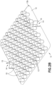
- FIGS. 2A and 2B show nest 5 with a "top" surface thereof being visible ( FIG.
- the nest 5 may include median finger notches 14 on two opposed edges of the main wall 12, with notch walls 15 delimiting the finger notches 14.
- the finger notches 14 allow the insertion of a user's fingers therethrough gripping the nest 5, and the notch walls 15 provide increased contact surfaces for these fingers.
- the nest 5 may be provided without the finger notches 14 and/or notch walls 15.
- the nest 5 may include additional features that allow for alignment and insertion of the nest into a storage tub.
- the nest 5 may include lateral positioning pillar notches on the first and second opposed edges that allow the insertion of the nest 5 on supporting pillars of a tub.
- the nest 5 may also include features that aid in rigidifying the nest 5.
- nest 5 could include a plurality of radial connection walls that extend between adjacent chimneys 10 in order to effectively connect the sidewalls 20 of chimneys 10 to one another, thereby aiding in rigidifying the nest 5.
- the complex molding parameters needed to create the nest 5 may lead to unpredictable curvature and/or deflection of the nest 5 after molding and/or sterilization, such as shown in FIG. 3 where top surface 12a of main wall 12 has a deflection angle A.
- the chimneys 10 in accordance with an aspect of the present disclosure are formed so as to accommodate curvature and/or deflection of the nest 5, thereby allowing the cylindrical bodies of syringe barrels to be inserted into and/or extracted from the chimneys 10 with a reduced likelihood of binding within the chimneys 10.
- each chimney 10 of the plurality of chimneys 10 of nest 5 may be configured as is shown in FIG. 3 .
- only a subset of chimneys 10 may be configured as is shown in FIG. 3 .
- the chimney 10 includes upper opening 11 and a lower opening 21 at opposing ends thereof.
- Each of the upper opening 11 and lower opening 21 is coaxially surrounded by the chimney 10, such that the cylindrical body of a syringe barrel may be inserted to and/or extracted from chimney 10 via the upper and lower openings 11, 21.
- the chimney 10 is generally defined by the sidewall 20 that extends down from the bottom surface 12b of main wall 12, between the upper opening 11 and the lower opening 21.
- the sidewall 20 may be characterized as having a top sidewall portion 20a and a bottom sidewall portion 20b, with the top sidewall portion 20a positioned adjacent upper opening 11 and extending down from main wall 12 and the bottom sidewall portion 20b positioned beneath the top sidewall portion 20a, distal from main wall 12.
- the top sidewall portion 20a and bottom sidewall portion 20b are separated by a dividing point 24 that, according to embodiments, may be a structurally defined dividing point 24 between the top and bottom sidewall portions 20a, 20b or a structurally undefined dividing point 24.
- the dividing point 24 is a edge/ridge junction from which the top sidewall portion 20a and bottom sidewall portion 20b diverge out at differing angles.
- each of the top sidewall portion 20a and bottom sidewall portion 20b has a draft angle, i.e., an angle of inclination of the sidewall portion, with the top sidewall portion 20a having a draft angle C between the upper opening 11 and the dividing point 24 and the bottom sidewall portion 20b having a draft angle B between the lower opening 21 and the dividing point 24. That is, the top sidewall portion 20a is angled outwardly from the dividing point 24 to the upper opening 11 at a first draft angle C and the bottom sidewall portion 20b is angled outwardly from the dividing point 24 to the lower opening 21 at a second draft angle B, which may be the same or different from draft angle C.
- a draft angle i.e., an angle of inclination of the sidewall portion
- a bottom portion of the chimney 10 thus has a frustoconical shape, while a top portion of the chimney 10 has an inverted frustoconical shape.
- the draft angle C, B of the top sidewall portion 20a and bottom sidewall portion 20b of chimney is relatively small.
- the draft angle C, B of the top and bottom sidewall portions 20a, 20b may be between 0° and 5°.
- the dividing point 24 between the top and bottom sidewall portions 20a, 20b may be vertically centered between the upper and lower openings 11, 21 or, as shown in FIG. 4 , may be vertically offset between the upper and lower openings 11, 21.
- the draft angle C of the top sidewall portion 20a may be equal and opposite to the draft angle B of the bottom sidewall portion 20b or may be different from the draft angle B of the bottom sidewall portion 20b.
- the size of the upper opening 11 and the size of the lower opening 21, i.e., a diameter D1 of the upper opening 11 and a diameter D2 of the lower opening 21, may be the same or different.
- the top sidewall portion 20a is longer than the bottom sidewall portion 20b, while the draft angle of the bottom sidewall portion 20b is greater than the draft angle of the top sidewall portion 20a, with the sidewall portion lengths and draft angles resulting in the diameter D1 of the upper opening 11 and the diameter D2 of the lower opening 21 being approximately equal.
- the chimney 10 is internally formed such that its smallest internal diameter D3, at the dividing point 24, is less than the diameter D1 of the upper opening 11 and less than the diameter D2 of the lower opening 21.
- the diameter D3 of the chimney 10 at the dividing point 24 is determined based on the diameter of the syringe barrel to be received in the chimney 10, with the diameter D3 being approximately equal to that of the syringe barrel so as to secure the syringe barrel within the chimney 10 when stored therein.
- the diameter D3 may thus be approximately 15.5 mm (+/- 0.1 mm).
- the diameters D1, D2 of the upper opening 11 and lower opening 21 are larger than the diameter D3 of the chimney 10 at dividing point 24, the diameters D1, D2 of the upper opening 11 and lower opening 21 may thus be approximately 17.6 mm and 16.3 mm (+/- 0.1 mm), respectively, for a syringe barrel of 5 ml in volume.
- the chimney 10 may also include a chamfered edge 25 at both the top and bottom thereof - i.e., between the main wall 12 and the top sidewall portion 20a and on bottom sidewall portion 20b adjacent opening 21.
- These chamfered edges 25 may have an outside diameter D4, D5 larger than the diameters D1, D2 of the upper and lower openings 11, 21, thereby providing for easier insertion/removal of a syringe barrel into and out from the chimney 10.
- chamfered edges 25 and the draft angles C, B of the top and bottom sidewall portions 20a, 20b provides a chimney 10 having what may be termed as "enlarged interior chamfer configurations" that aid in insertion and/or extraction of a syringe barrel from the nest 5, as explained in more detail below.
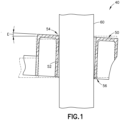
- the structure of the chimney 10 as described above beneficially allows for some variance to be present in the nest 5 (resulting from the molding fabrication thereof) without affecting the performance thereof. That is, as described above and shown in FIG. 1 , in a typical nest 40, a curvature and/or deflection of the nest 40 may occur during fabrication thereof that adversely affects performance of an automated filling machine, such as when the curvature or deflection of the top surface 50 of the nest 40 (and, thus, an associated angulation of the chimney 54) does not allow for a typical vertical placement or removal of a syringe barrel 60.
- a curvature or deflection E of the top surface 50 of more than 2.5 mm, for example, may result in syringe barrels 60 becoming lodged within associated chimneys 54 during insertion and/or extraction of a syringe barrel 60 from the nest 40.
- the structure of chimney 10 allows for a curvature or deflection of the top surface 12a of nest 5 to be present without affecting the vertical placement or removal of a syringe barrel 60 from the chimney 10.
- a curvature or deflection of the top surface 12a of up to 5° may be present without affecting the ability of a syringe barrel 60 to be inserted to or extracted from the chimney 10.
- the syringe barrel 60 makes contact with an inner edge of the chamfered surface 25 and with the top sidewall portion 20a along one side of the syringe barrel 60 and makes contact with the bottom sidewall portion 20b along the opposite side of the syringe barrel 60.
- the arrangement of the syringe barrel 60 relative to the chimney 10 in this manner facilitated by the size of the upper and lower openings 11, 21 and the orientation of the top and bottom sidewall portions 20a, 20b, allows for the syringe barrel 60 to be stored in a generally vertical orientation.
- the generally vertical orientation of the syringe barrel 60 within chimney 10 enables a smooth insertion and extraction of the syringe barrel 60 from the nest 5, thereby preventing occurrences of the syringe barrel 60 becoming lodged within a respective chimney 10.
- each chimney 70 of the plurality of chimneys 70 of nest 5 may be configured as is shown in FIG. 5 or, alternatively, only a subset of chimneys 70 may be configured as is shown in FIG. 5 .
- the chimney 70 includes an upper opening 71 and a lower opening 72 at opposing ends thereof.
- Each of the upper opening 71 and lower opening 72 is coaxially surrounded by the chimney 70, such that the cylindrical body of a syringe barrel may be inserted to and/or extracted from chimney 70 via the upper and lower openings 71, 72.
- the chimney 70 is generally defined by a sidewall 74 that extends down from main wall 12, between the upper opening 71 and the lower opening 72.
- the sidewall 74 may be characterized as having a top sidewall portion 74a and a bottom sidewall portion 74b, with the top sidewall portion 74a positioned adjacent upper opening 71 and extending down from main wall 12 and the bottom sidewall portion 74b positioned beneath the top sidewall portion 74a, distal from main wall 12.
- the top sidewall portion 74a and bottom sidewall portion 74b are separated by a dividing point 82 that, in the illustrated embodiment, is a horizontally oriented ledge 74c that separates the top sidewall portion 74a from the bottom sidewall portion 74b.
- the horizontally oriented ledge 74c extends inwardly from a bottom edge of the top sidewall portion 74a to a top edge of the bottom sidewall portion 74b.
- the top sidewall portion 74a has a generally vertical orientation while the bottom sidewall portion 74b has a draft angle G between the lower opening 72 and the dividing point 82, with the bottom sidewall portion 74b being angled outwardly from the ledge 74c to the lower opening 72.
- the draft angle G of bottom sidewall portion 74b may be between 0° and 5°.
- the dividing point 82 between the top and bottom sidewall portions 74a, 74b may be vertically centered between the upper and lower openings 71, 72 or, as shown in FIG. 6 , may be vertically offset between the upper and lower openings 71, 72.
- the size of the upper opening 71 and the size of the lower opening 72 i.e., a diameter D6 of the upper opening 71 and a diameter D7 of the lower opening 72, may be the same or different.
- the top sidewall portion 74a is longer than the bottom sidewall portion 74b and the draft angle G of the bottom sidewall portion 74b is such that the diameter D6 of the upper opening 71 and the diameter D7 of the lower opening 72 are approximately equal.
- the chimney 70 is internally formed such that its smallest internal diameter D8, at the dividing point 82, is less than the diameter D6 of the upper opening 71 and less than the diameter D7 of the lower opening 72.
- the diameter D8 of the chimney 70 at the dividing point 82 is determined based on the diameter of the syringe barrel to be received in the chimney 70, with the diameter D8 being approximately equal to that of the syringe barrel so as to secure the syringe barrel within the chimney 70 when stored therein.
- the diameter D8 may thus be approximately 15.5 mm
- the diameters D6, D7 of the upper opening 71 and lower opening 72 may thus be approximately 17.6 mm and 16.3 mm, respectively.
- the chimney 70 may also include chamfered edges 76 at both the top and bottom thereof - i.e., between the main wall 12 and the top sidewall portion 74a and on bottom sidewall portion 74b adjacent opening 72.
- These chamfered edges 76 may have an outside diameter D9, D10 larger than the diameters D6, D7 of the upper and lower openings 71, 72, thereby providing for easier insertion of a syringe barrel into the chimney 70 and removal of the syringe barrel from the chimney 70.
- the structure of the chimney 70 beneficially allows for a curvature or deflection of the top surface 12a of nest 5 to be present without affecting the vertical placement or removal of a syringe barrel from the chimney 70.
- a curvature or deflection of the top surface 12a of up to 5° may be present without affecting the ability of a syringe barrel to be inserted to or extracted from the chimney 70 in a generally vertical orientation, so as to prevent occurrences of the syringe barrel becoming lodged within a respective chimney 70.
- the inclusion of the ledge 74c in the sidewall 74 chimney 70 further increases and optimizes a thickness of the sidewall of chimney 70, so as to improve molding quality in the nest 5 that reduces sink mark risks.
- Embodiments of the disclosure thus provide a nest having chimneys therein that counteract a high curvature of a top surface of the nest that might result from molding and/or sterilization of the nest.
- a nest with a chimney structure as described in accordance with embodiments of the present disclosure provides a higher flatness tolerance window for the top surface of the nest within which the nest may be molded and sterilized, while still allowing syringe barrels to be stored in a generally vertical orientation in the nest, such that the syringe barrels will not become lodged within the chimneys when they are inserted into or extracted out therefrom. Accordingly, the nests of the present disclosure can minimize the downtime of automated processing lines (i.e., automated filling machines) with which the nests are used.
- automated processing lines i.e., automated filling machines
Landscapes
- Health & Medical Sciences (AREA)
- Life Sciences & Earth Sciences (AREA)
- Surgery (AREA)
- Animal Behavior & Ethology (AREA)
- Veterinary Medicine (AREA)
- Engineering & Computer Science (AREA)
- Public Health (AREA)
- General Health & Medical Sciences (AREA)
- Biomedical Technology (AREA)
- Heart & Thoracic Surgery (AREA)
- Molecular Biology (AREA)
- Medical Informatics (AREA)
- Nuclear Medicine, Radiotherapy & Molecular Imaging (AREA)
- Pharmacology & Pharmacy (AREA)
- Mechanical Engineering (AREA)
- Vascular Medicine (AREA)
- Anesthesiology (AREA)
- Hematology (AREA)
- Infusion, Injection, And Reservoir Apparatuses (AREA)
- Prostheses (AREA)
Priority Applications (4)
| Application Number | Priority Date | Filing Date | Title |
|---|---|---|---|
| EP23306443.5A EP4527427A1 (de) | 2023-08-31 | 2023-08-31 | Nest mit vergrösserter innerer kaminabschrägung |
| CN202480056136.6A CN121752311A (zh) | 2023-08-31 | 2024-08-30 | 具有扩大的内部筒座倒角的巢体 |
| PCT/US2024/044655 WO2025049894A1 (en) | 2023-08-31 | 2024-08-30 | Nest with enlarged interior chimney chamfer |
| MX2026002447A MX2026002447A (es) | 2023-08-31 | 2026-02-27 | Nido con chaflan de chimenea interior ampliado |
Applications Claiming Priority (1)
| Application Number | Priority Date | Filing Date | Title |
|---|---|---|---|
| EP23306443.5A EP4527427A1 (de) | 2023-08-31 | 2023-08-31 | Nest mit vergrösserter innerer kaminabschrägung |
Publications (1)
| Publication Number | Publication Date |
|---|---|
| EP4527427A1 true EP4527427A1 (de) | 2025-03-26 |
Family
ID=88018081
Family Applications (1)
| Application Number | Title | Priority Date | Filing Date |
|---|---|---|---|
| EP23306443.5A Pending EP4527427A1 (de) | 2023-08-31 | 2023-08-31 | Nest mit vergrösserter innerer kaminabschrägung |
Country Status (4)
| Country | Link |
|---|---|
| EP (1) | EP4527427A1 (de) |
| CN (1) | CN121752311A (de) |
| MX (1) | MX2026002447A (de) |
| WO (1) | WO2025049894A1 (de) |
Families Citing this family (1)
| Publication number | Priority date | Publication date | Assignee | Title |
|---|---|---|---|---|
| US20250136325A1 (en) * | 2023-10-30 | 2025-05-01 | West Pharmaceutical Services, Inc. | Packaging for containers |
Citations (3)
| Publication number | Priority date | Publication date | Assignee | Title |
|---|---|---|---|---|
| US20010052476A1 (en) * | 2000-03-15 | 2001-12-20 | Jochen Heinz | Transport device for medicinal containers |
| US20160089205A1 (en) * | 2010-03-12 | 2016-03-31 | Barry Peter Liversidge | Tray for Handling Syringe Barrels |
| WO2018020505A1 (en) * | 2016-07-27 | 2018-02-01 | Schott Kaisha Pvt. Ltd. | Method for closing vials, supporting structure for vial stopper members and transport or packaging container |
-
2023
- 2023-08-31 EP EP23306443.5A patent/EP4527427A1/de active Pending
-
2024
- 2024-08-30 CN CN202480056136.6A patent/CN121752311A/zh active Pending
- 2024-08-30 WO PCT/US2024/044655 patent/WO2025049894A1/en active Pending
-
2026
- 2026-02-27 MX MX2026002447A patent/MX2026002447A/es unknown
Patent Citations (3)
| Publication number | Priority date | Publication date | Assignee | Title |
|---|---|---|---|---|
| US20010052476A1 (en) * | 2000-03-15 | 2001-12-20 | Jochen Heinz | Transport device for medicinal containers |
| US20160089205A1 (en) * | 2010-03-12 | 2016-03-31 | Barry Peter Liversidge | Tray for Handling Syringe Barrels |
| WO2018020505A1 (en) * | 2016-07-27 | 2018-02-01 | Schott Kaisha Pvt. Ltd. | Method for closing vials, supporting structure for vial stopper members and transport or packaging container |
Also Published As
| Publication number | Publication date |
|---|---|
| MX2026002447A (es) | 2026-04-01 |
| WO2025049894A1 (en) | 2025-03-06 |
| CN121752311A (zh) | 2026-03-27 |
Similar Documents
| Publication | Publication Date | Title |
|---|---|---|
| CN102470072B (zh) | 用于药物小容器的接收容器 | |
| US9630745B2 (en) | Packaging for the storage, protection and transport of syringes | |
| US9408965B2 (en) | Method and system for handling and transporting syringes | |
| CN114889956B (zh) | 用以支承医用容器的包装装置和用于从所述包装装置移除医用容器的方法 | |
| CN111163815B (zh) | 包装装置和用于从所述包装装置移除医用容器的方法 | |
| US20250161557A1 (en) | Tub for the Packaging of a Plurality of Nests of Plunger Stoppers With Guiding Features Ensuring a Reliable Location of the Nests Within the Tub | |
| EP4527427A1 (de) | Nest mit vergrösserter innerer kaminabschrägung | |
| JP7843291B2 (ja) | ネストの山(pile)の信頼性の高い位置合わせを保証するスタッキングピン付きプランジャーストッパの梱包用ネスト | |
| US12257415B2 (en) | Nest for the packaging of plunger stoppers with integrated stacking features ensuring a reliable alignment of a pile of nests | |
| US12311375B2 (en) | Nest for the packaging of plunger stoppers with clips ensuring a reliable alignment of several nests in a tub |
Legal Events
| Date | Code | Title | Description |
|---|---|---|---|
| PUAI | Public reference made under article 153(3) epc to a published international application that has entered the european phase |
Free format text: ORIGINAL CODE: 0009012 |
|
| STAA | Information on the status of an ep patent application or granted ep patent |
Free format text: STATUS: THE APPLICATION HAS BEEN PUBLISHED |
|
| AK | Designated contracting states |
Kind code of ref document: A1 Designated state(s): AL AT BE BG CH CY CZ DE DK EE ES FI FR GB GR HR HU IE IS IT LI LT LU LV MC ME MK MT NL NO PL PT RO RS SE SI SK SM TR |
|
| STAA | Information on the status of an ep patent application or granted ep patent |
Free format text: STATUS: REQUEST FOR EXAMINATION WAS MADE |
|
| 17P | Request for examination filed |
Effective date: 20250918 |
|
| STAA | Information on the status of an ep patent application or granted ep patent |
Free format text: STATUS: EXAMINATION IS IN PROGRESS |
|
| 17Q | First examination report despatched |
Effective date: 20260324 |