EP4527335A2 - Virtuelles 3d-bild mit virtueller beleuchtung zur verfolgung der bewegung eines mit einem sensor ausgestatteten medizinischen instruments - Google Patents
Virtuelles 3d-bild mit virtueller beleuchtung zur verfolgung der bewegung eines mit einem sensor ausgestatteten medizinischen instruments Download PDFInfo
- Publication number
- EP4527335A2 EP4527335A2 EP24200966.0A EP24200966A EP4527335A2 EP 4527335 A2 EP4527335 A2 EP 4527335A2 EP 24200966 A EP24200966 A EP 24200966A EP 4527335 A2 EP4527335 A2 EP 4527335A2
- Authority
- EP
- European Patent Office
- Prior art keywords
- patient
- instrument
- indicator
- image
- distal portion
- Prior art date
- Legal status (The legal status is an assumption and is not a legal conclusion. Google has not performed a legal analysis and makes no representation as to the accuracy of the status listed.)
- Pending
Links
Images


Classifications
-
- A—HUMAN NECESSITIES
- A61—MEDICAL OR VETERINARY SCIENCE; HYGIENE
- A61B—DIAGNOSIS; SURGERY; IDENTIFICATION
- A61B34/00—Computer-aided surgery; Manipulators or robots specially adapted for use in surgery
- A61B34/20—Surgical navigation systems; Devices for tracking or guiding surgical instruments, e.g. for frameless stereotaxis
-
- A—HUMAN NECESSITIES
- A61—MEDICAL OR VETERINARY SCIENCE; HYGIENE
- A61B—DIAGNOSIS; SURGERY; IDENTIFICATION
- A61B34/00—Computer-aided surgery; Manipulators or robots specially adapted for use in surgery
- A61B34/10—Computer-aided planning, simulation or modelling of surgical operations
-
- A—HUMAN NECESSITIES
- A61—MEDICAL OR VETERINARY SCIENCE; HYGIENE
- A61B—DIAGNOSIS; SURGERY; IDENTIFICATION
- A61B90/00—Instruments, implements or accessories specially adapted for surgery or diagnosis and not covered by any of the groups A61B1/00 - A61B50/00, e.g. for luxation treatment or for protecting wound edges
- A61B90/36—Image-producing devices or illumination devices not otherwise provided for
-
- A—HUMAN NECESSITIES
- A61—MEDICAL OR VETERINARY SCIENCE; HYGIENE
- A61B—DIAGNOSIS; SURGERY; IDENTIFICATION
- A61B34/00—Computer-aided surgery; Manipulators or robots specially adapted for use in surgery
- A61B34/10—Computer-aided planning, simulation or modelling of surgical operations
- A61B2034/101—Computer-aided simulation of surgical operations
- A61B2034/105—Modelling of the patient, e.g. for ligaments or bones
-
- A—HUMAN NECESSITIES
- A61—MEDICAL OR VETERINARY SCIENCE; HYGIENE
- A61B—DIAGNOSIS; SURGERY; IDENTIFICATION
- A61B34/00—Computer-aided surgery; Manipulators or robots specially adapted for use in surgery
- A61B34/10—Computer-aided planning, simulation or modelling of surgical operations
- A61B2034/107—Visualisation of planned trajectories or target regions
-
- A—HUMAN NECESSITIES
- A61—MEDICAL OR VETERINARY SCIENCE; HYGIENE
- A61B—DIAGNOSIS; SURGERY; IDENTIFICATION
- A61B34/00—Computer-aided surgery; Manipulators or robots specially adapted for use in surgery
- A61B34/20—Surgical navigation systems; Devices for tracking or guiding surgical instruments, e.g. for frameless stereotaxis
- A61B2034/2046—Tracking techniques
- A61B2034/2051—Electromagnetic tracking systems
-
- A—HUMAN NECESSITIES
- A61—MEDICAL OR VETERINARY SCIENCE; HYGIENE
- A61B—DIAGNOSIS; SURGERY; IDENTIFICATION
- A61B34/00—Computer-aided surgery; Manipulators or robots specially adapted for use in surgery
- A61B34/20—Surgical navigation systems; Devices for tracking or guiding surgical instruments, e.g. for frameless stereotaxis
- A61B2034/2046—Tracking techniques
- A61B2034/2055—Optical tracking systems
-
- A—HUMAN NECESSITIES
- A61—MEDICAL OR VETERINARY SCIENCE; HYGIENE
- A61B—DIAGNOSIS; SURGERY; IDENTIFICATION
- A61B34/00—Computer-aided surgery; Manipulators or robots specially adapted for use in surgery
- A61B34/20—Surgical navigation systems; Devices for tracking or guiding surgical instruments, e.g. for frameless stereotaxis
- A61B2034/2072—Reference field transducer attached to an instrument or patient
-
- A—HUMAN NECESSITIES
- A61—MEDICAL OR VETERINARY SCIENCE; HYGIENE
- A61B—DIAGNOSIS; SURGERY; IDENTIFICATION
- A61B90/00—Instruments, implements or accessories specially adapted for surgery or diagnosis and not covered by any of the groups A61B1/00 - A61B50/00, e.g. for luxation treatment or for protecting wound edges
- A61B90/08—Accessories or related features not otherwise provided for
- A61B2090/0807—Indication means
-
- A—HUMAN NECESSITIES
- A61—MEDICAL OR VETERINARY SCIENCE; HYGIENE
- A61B—DIAGNOSIS; SURGERY; IDENTIFICATION
- A61B90/00—Instruments, implements or accessories specially adapted for surgery or diagnosis and not covered by any of the groups A61B1/00 - A61B50/00, e.g. for luxation treatment or for protecting wound edges
- A61B90/36—Image-producing devices or illumination devices not otherwise provided for
- A61B2090/364—Correlation of different images or relation of image positions in respect to the body
- A61B2090/365—Correlation of different images or relation of image positions in respect to the body augmented reality, i.e. correlating a live optical image with another image
-
- A—HUMAN NECESSITIES
- A61—MEDICAL OR VETERINARY SCIENCE; HYGIENE
- A61B—DIAGNOSIS; SURGERY; IDENTIFICATION
- A61B34/00—Computer-aided surgery; Manipulators or robots specially adapted for use in surgery
- A61B34/25—User interfaces for surgical systems
Definitions
- Image-guided surgery is a technique where a computer is used to obtain a real-time correlation of the location of an instrument that has been inserted into a patient's body to a set of preoperatively obtained images (e.g., a CT or MRI scan, 3-D map, etc.), such that the computer system may superimpose the current location of the instrument on the preoperatively obtained images.
- a set of preoperatively obtained images e.g., a CT or MRI scan, 3-D map, etc.
- An example of an electromagnetic IGS navigation system that may be used in IGS procedures is the TRUDI ® Navigation System by Acclarent, Inc., of Irvine, California.
- a digital tomographic scan e.g., CT or MRI, 3-D map, etc.
- a specially programmed computer is then used to convert the digital tomographic scan data into a digital map.
- special instruments having sensors (e.g., electromagnetic coils that emit electromagnetic fields and/or are responsive to externally generated electromagnetic fields) are used to perform the procedure while the sensors send data to the computer indicating the current position of each surgical instrument.
- the computer correlates the data it receives from the sensors with the digital map that was created from the preoperative tomographic scan.
- the tomographic scan images are displayed on a video monitor along with an indicator (e.g., crosshairs or an illuminated dot, etc.) showing the real-time position of each surgical instrument relative to the anatomical structures shown in the scan images.
- an indicator e.g., crosshairs or an illuminated dot, etc.
- an anatomical passageway in a patient. This may include dilation of ostia of paranasal sinuses (e.g., to treat sinusitis), dilation of the larynx, dilation of the Eustachian tube, dilation of other passageways within the ear, nose, or throat, etc.
- One method of dilating anatomical passageways includes using a guide wire and catheter to position an inflatable balloon within the anatomical passageway, then inflating the balloon with a fluid (e.g., saline) to dilate the anatomical passageway.
- a fluid e.g., saline
- the expandable balloon may be positioned within an ostium at a paranasal sinus and then be inflated, to thereby dilate the ostium by remodeling the bone adjacent to the ostium, without requiring incision of the mucosa or removal of any bone.
- the dilated ostium may then allow for improved drainage from and ventilation of the affected paranasal sinus.
- the navigation sensor of the instrument may comprise at least one coil at or near the distal end of the instrument.
- the alternating magnetic field may generate electrical current in the coil, and this electrical current may be communicated as a signal along the electrical conduit(s) in the instrument and further to processor (52) via the coupling unit.
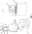
- This phenomenon may enable IGS navigation system (50) to determine the location of the distal end of the instrument within a three-dimensional space (i.e., within the head (H) of the patient (P), etc.).
- processor (52) executes an algorithm to calculate location coordinates of the distal end of the instrument from the position related signals of the coil(s) in the instrument.
- a navigation sensor may serve as a position sensor by providing signals indicating the real-time position of the sensor within three-dimensional space.
- Display screen (56) may display such images simultaneously and/or superimposed on each other during the surgical procedure. Such displayed images may also include graphical representations of instruments that are inserted in the patient's head (H), such that the operator may view the virtual rendering of the instrument at its actual location in real time.
- display screen (56) may provide images in accordance with at least some of the teachings of U.S. Pat. No. 10,463,242, entitled “Guidewire Navigation for Sinuplasty,” issued November 5, 2019 , the disclosure of which is incorporated by reference herein, in its entirety.
- the endoscopic image may also be provided on display screen (56).
- the images provided through display screen (56) may help guide the operator in maneuvering and otherwise manipulating instruments within the patient's head (H). It should also be understood that other components of a surgical instrument and other kinds of surgical instruments, as described below, may incorporate a navigation sensor like the navigation sensor described above.
- end effector (110) includes one or more electrodes that is/are operable to provide ablative remodeling of tissue, denervation, or other effects.
- end effector (110) includes a rotary feature such as a microbur, shaver blade, drill bit, microdebrider, etc.
- End effector (110) may also include features to provide endoscopic visualization, illumination, irrigation, suction, and/or other effects.
- end effector (110) may include one or more channels through which one or more other instruments may pass. Other suitable forms, features, and operabilities that may be provided in or through end effector (110) will be apparent to those skilled in the art in view of the teachings herein.
- instrument (100) may also comprise a guidewire.
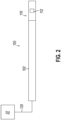
- Instrument (100) further includes a position sensor (112) at end effector (110).
- Position sensor (112) is integrated in end effector (110) in this example, though other variations may provide position sensor (112) within a guidewire, guide rail, or other element that is movably disposed within end effector (110); or within a guide sheath or other element that is movably disposed about end effector (110). While only one position sensor (112) is shown, instrument (100) may include two or more position sensors (112), with position sensors (112) being located at any suitable position(s) along the length of shaft (102) and/or in end effector (110).
- Position sensor (112) of the present example comprises one or more coils configured to provide position-indicative signals in response to alternating electromagnetic fields generated by field generators (64).
- the signals provided by position sensor (112) in response to such alternating electromagnetic fields may indicate the position of position sensor (112) in three-dimensional space.
- the signals provided by position sensor (112) in response to such alternating electromagnetic fields may indicate the orientation of position sensor (112) in three-dimensional space.
- Processor (52) is further operable to provide video in real time via display screen (56), showing the position of end effector (110) in relation to a video camera image of the patient's head (H), a CT scan image of the patient's head (H), and/or a computer-generated three-dimensional model of the anatomy within and adjacent to the patient's nasal cavity.
- Display screen (56) may display such images simultaneously and/or superimposed on each other during the surgical procedure.
- Such displayed images may also include a graphical representation of instrument (100), such that the operator may view the virtual rendering of instrument (100) at its actual location in real time.
- the real-time position of end effector (110) is represented on display screen (56) by a crosshairs, dot, circle, or other form of visual indication.
- processor (52) may drive display screen (56) to provide a visual indication of the real-time position of end effector (110) in relation to one or more images of the head (H) of the patient (P).
- processor (52) may drive display screen (56) to provide a visual indication of the real-time position of end effector (110) in relation to one or more images of the head (H) of the patient (P).
- the operator may benefit from an enhanced view that provides an intuitive visual sense of the real-time orientation of end effector (110) within the patient (P).
- the operator may also benefit from an enhanced view that provides a real-time indication of proximity between end effector (110) and one or more identified anatomical regions.
- the following description provides examples of such enhancements that may be provided via display screen (56). While the examples are provided in the context of end effector (110) being used in an ear, nose, or throat procedure, the below teachings may be readily applied to other procedures within a head (H) of a patient (P) (e.g., intracranial navigation, such as for navigation toward a blood clot or aneurysm, etc.). Similarly, the below teachings may be readily applied in any other anatomical context, such that the following teachings are not limited to the context of procedures performed in the head (H) of a patient (P).
- FIGS. 3-5 show an example of how processor (52) may drive display screen (56) to provide an intuitive visual indication of the position and orientation of end effector (110) via a virtual illumination projection.
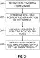
- FIG. 3 shows an example of a process that begins with processor (52) receiving (block 200) real-time data from position sensor (112).
- instrument (100) may include two or more position sensors (112), such that processor (52) may receive (block 200) real-time data from such two or more position sensors (112).
- processor (52) may then determine (block 202) the real-time position and orientation of instrument (100) in three-dimensional space. More specifically, processor (52) may determine (block 202) the real-time position and orientation of end effector (110) in the head (H) of the patient (P).
- processor (52) may drive display screen (56) to provide (block 204) a visual indication of the real-time position of end effector (110) relative to one or more images of the patient (P).
- processor (52) may drive display screen (56) to provide (block 206) a visual indication of the real-time orientation of end effector (110) relative to one or more images of the patient (P).
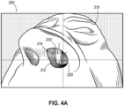
- FIGS. 4A-4B show one example of how processor (52) may drive display screen (56) to provide (blocks 204, 206) a visual indication of the real-time position and orientation of end effector (110) relative to one or more images of the patient (P).
- FIG. 4A shows an example of an image (300) that may be rendered on display screen (56), where image (300) includes a three-dimensional virtual representation (310) of the head (H) of the patient (P).
- This image (300) includes a first indicator (320) representing the real-time position of end effector (110); and a second indicator (330) representing the real-time orientation of end effector (110).
- second indicator (330) may provide the operator with a better, more intuitive understanding of the contours and other surface features of anatomical structures (e.g., within a nasal cavity), particularly to the extent that the virtual illumination provides shadows and other effects that would be experience through actual illumination within anatomical cavities and passageways.
- a first indicator (354) in image (350) indicates the real-time position of end effector (110); and a second indicator (356) in image (350) indicates the real-time orientation of end effector (110).
- first indicator (354) is in the form of a crosshairs intersecting at the location corresponding to the real-time position of end effector (110).
- first indicator (354) may take any other suitable form, including but not limited to an "X," a circle, a dot, etc.
- Second indicator (356) is in the form of a virtual illumination.
- indicators (354, 356) in image (350) are configured and operable like indicators (320, 330) of image (300), respectively.
- Example 4 The system of Example 4, the end effector including an endoscopic visualization element.
- Example 4 The system of Example 4, the end effector including an irrigation opening configured to communicate irrigation fluid.
- Example 4 The system of Example 4, the end effector including a suction opening configured to communicate suction.
- the system of Example 13 the processor being further configured to: (i) modify a viewing perspective of the three-dimensional virtual representation of the anatomical region of the patient in response to signals from the position sensor indicating repositioning of the distal portion of the instrument within the patient, (ii) provide the first indicator on the three-dimensional virtual representation of the anatomical region of the patient with the modified viewing perspective, and (iii) provide the second indicator on the three-dimensional virtual representation of the anatomical region of the patient with the modified viewing perspective.
- the processor being further configured to: (i) drive the display screen to simultaneously display two or more images of the anatomical region of the patient, (ii) provide the first indicator simultaneously on the two or more images the anatomical region of the patient, and (iii) provide the second indicator simultaneously on the two or more images the anatomical region of the patient.
- the virtual illumination being configured to simulate illumination from a virtual light source positioned at a distal tip of the instrument.
- Example 1 through 20 the processor being further configured to: (i) persistently illuminate a third indicator on the image with a first illumination characteristic in response to determining that the distal portion of the instrument is outside a certain proximity of an identified anatomical structure, and (ii) persistently illuminate the third indicator on the image with a second illumination characteristic in response to determining that the distal portion of the instrument is within a certain proximity of the identified anatomical structure.
- Example 21 The system of Example 21, the first illumination characteristic comprising a first color, the second illumination characteristic comprising a second color.
- the first illumination characteristic comprising a first flash frequency
- the second illumination characteristic comprising a second flash frequency
- the first illumination characteristic comprising a first illumination intensity
- the second illumination characteristic comprising a second illumination intensity
- a method comprising: (a) driving a display screen to display an image of an anatomical region of a patient; (b) processing signals from a position sensor of an instrument to determine the real-time position and orientation of a distal portion of the instrument within the patient; (c) providing a first indicator on the image, the first indicator indicating the real-time position of the distal portion of the instrument within the patient; and (d) providing a second indicator on the image, the second indicator indicating the real-time orientation of the distal portion of the instrument within the patient, the second indicator including virtual illumination of an anatomical structure within the image, the virtually illuminated anatomical structure including a structure toward which the distal portion of the instrument is oriented.
- the displayed image comprising a three-dimensional virtual representation of the anatomical region of the patient, the first indicator being provided on the three-dimensional virtual representation of the anatomical region of the patient, the second indicator being provided on the three-dimensional virtual representation of the anatomical region of the patient.
- the displayed image comprising a cross-sectional image of the anatomical region of the patient, the first indicator being provided on the cross-sectional image of the anatomical region of the patient, the second indicator being provided on the cross-sectional image of the anatomical region of the patient.
- Example 29 further comprising: (a) modifying a cross-sectional plane position of the cross-sectional image of the anatomical region of the patient in response to signals from the position sensor indicating repositioning of the distal portion of the instrument within the patient; (b) providing the first indicator on the cross-sectional image of the anatomical region of the patient with the modified cross-sectional plane position; and (c) providing the second indicator on the cross-sectional image of the anatomical region of the patient with the modified cross-sectional plane position.
- the method of any of Examples 25 through 30, further comprising: (a) driving the display screen to simultaneously display two or more images of the anatomical region of the patient; (b) providing the first indicator simultaneously on the two or more images the anatomical region of the patient; and (c) providing the second indicator simultaneously on the two or more images the anatomical region of the patient.
- Example 25 further comprising: (a) persistently illuminating a third indicator on the image with a first illumination characteristic in response to determining that the distal portion of the instrument is outside a certain proximity of an identified anatomical structure; and (b) persistently illuminating the third indicator on the image with a second illumination characteristic in response to determining that the distal portion of the instrument is within a certain proximity of an identified anatomical structure.
- Example 35 The method of Example 35, the first illumination characteristic comprising a first color, the second illumination characteristic comprising a second color.
- the first illumination characteristic comprising a first flash frequency
- the second illumination characteristic comprising a second flash frequency
- the first illumination characteristic comprising a first illumination intensity
- the second illumination characteristic comprising a second illumination intensity
- the first illumination characteristic comprising a first illumination intensity
- the second illumination characteristic comprising a second illumination intensity
- the processor being further configured to provide a second indicator on the image, the second indicator indicating the real-time position of the distal portion of the instrument within the patient.
- the processor being further configured to: (i) process signals from the position sensor to determine the real-time orientation of the distal portion of the instrument within the patient, and (ii) provide a third indicator on the image, the third indicator indicating the real-time orientation of the distal portion of the instrument within the patient, the third indicator including virtual illumination of an anatomical structure within the image, the virtually illuminated anatomical structure including a structure toward which the distal portion of the instrument is oriented.
- a method comprising: (a) driving a display screen to display an image of an anatomical region of a patient; (b) processing signals from a position sensor to determine the real-time position of a distal portion of an instrument within the patient; (c) determining whether the distal portion of the instrument is within a certain proximity of an identified anatomical structure; and (d) persistently illuminating a first indicator on the image with a first illumination characteristic while the distal portion of the instrument is outside the certain proximity of the identified anatomical structure; and (e) if the distal portion of the instrument reaches the certain proximity of the identified anatomical structure, persistently illuminating the first indicator on the image with a second illumination characteristic to thereby indicate that the distal portion of the instrument is within the certain proximity of the identified anatomical structure.
- Example 46 further comprising receiving operator input indicating the identified anatomical structure.
- the first illumination characteristic comprising a first color
- the second illumination characteristic comprising a second color
- the first illumination characteristic comprising a first flash frequency
- the second illumination characteristic comprising a second flash frequency
- the first illumination characteristic comprising a first illumination intensity
- the second illumination characteristic comprising a second illumination intensity
- the first indicator being positioned within a region of the image corresponding to the identified anatomical structure.
- the anatomical region of the patient including a head of the patient, the distal portion of the instrument being inserted in the head of the patient.
- the system of any of Examples 46 through 54 further comprising: (a) processing signals from the position sensor to determine the real-time orientation of the distal portion of the instrument within the patient; and (b) providing a third indicator on the image, the third indicator indicating the real-time orientation of the distal portion of the instrument within the patient, the third indicator including virtual illumination of an anatomical structure within the image, the virtually illuminated anatomical structure including a structure toward which the distal portion of the instrument is oriented.
- Versions of the devices described above may be designed to be disposed of after a single use, or they can be designed to be used multiple times. Versions may, in either or both cases, be reconditioned for reuse after at least one use. Reconditioning may include any combination of the steps of disassembly of the device, followed by cleaning or replacement of particular pieces, and subsequent reassembly. In particular, some versions of the device may be disassembled, and any number of the particular pieces or parts of the device may be selectively replaced or removed in any combination. Upon cleaning and/or replacement of particular parts, some versions of the device may be reassembled for subsequent use either at a reconditioning facility or by a user immediately prior to a procedure.
- reconditioning of a device may utilize a variety of techniques for disassembly, cleaning/replacement, and reassembly. Use of such techniques, and the resulting reconditioned device, are all within the scope of the present application.
- versions described herein may be sterilized before and/or after a procedure.
- the device is placed in a closed and sealed container, such as a plastic or TYVEK bag.
- the container and device may then be placed in a field of radiation that can penetrate the container, such as gamma radiation, x-rays, or high-energy electrons.
- the radiation may kill bacteria on the device and in the container.
- the sterilized device may then be stored in the sterile container for later use.
- a device may also be sterilized using any other technique known in the art, including but not limited to beta or gamma radiation, ethylene oxide, or steam.
Landscapes
- Health & Medical Sciences (AREA)
- Surgery (AREA)
- Life Sciences & Earth Sciences (AREA)
- Engineering & Computer Science (AREA)
- Molecular Biology (AREA)
- Animal Behavior & Ethology (AREA)
- Veterinary Medicine (AREA)
- Biomedical Technology (AREA)
- Heart & Thoracic Surgery (AREA)
- Medical Informatics (AREA)
- Nuclear Medicine, Radiotherapy & Molecular Imaging (AREA)
- Public Health (AREA)
- General Health & Medical Sciences (AREA)
- Robotics (AREA)
- Pathology (AREA)
- Oral & Maxillofacial Surgery (AREA)
- Endoscopes (AREA)
- Media Introduction/Drainage Providing Device (AREA)
- Measurement Of The Respiration, Hearing Ability, Form, And Blood Characteristics Of Living Organisms (AREA)
- Surgical Instruments (AREA)
Applications Claiming Priority (2)
| Application Number | Priority Date | Filing Date | Title |
|---|---|---|---|
| US202363539118P | 2023-09-19 | 2023-09-19 | |
| US18/804,238 US20250090237A1 (en) | 2023-09-19 | 2024-08-14 | 3d virtual image with virtual lighting to track movement of sensor-equipped medical instrument |
Publications (2)
| Publication Number | Publication Date |
|---|---|
| EP4527335A2 true EP4527335A2 (de) | 2025-03-26 |
| EP4527335A3 EP4527335A3 (de) | 2025-05-21 |
Family
ID=92843108
Family Applications (1)
| Application Number | Title | Priority Date | Filing Date |
|---|---|---|---|
| EP24200966.0A Pending EP4527335A3 (de) | 2023-09-19 | 2024-09-18 | Virtuelles 3d-bild mit virtueller beleuchtung zur verfolgung der bewegung eines mit einem sensor ausgestatteten medizinischen instruments |
Country Status (5)
| Country | Link |
|---|---|
| US (1) | US20250090237A1 (de) |
| EP (1) | EP4527335A3 (de) |
| JP (1) | JP2025044171A (de) |
| CN (1) | CN119655881A (de) |
| IL (1) | IL315483A (de) |
Citations (4)
| Publication number | Priority date | Publication date | Assignee | Title |
|---|---|---|---|---|
| US7720521B2 (en) | 2004-04-21 | 2010-05-18 | Acclarent, Inc. | Methods and devices for performing procedures within the ear, nose, throat and paranasal sinuses |
| US10463242B2 (en) | 2014-07-09 | 2019-11-05 | Acclarent, Inc. | Guidewire navigation for sinuplasty |
| US10561370B2 (en) | 2017-04-26 | 2020-02-18 | Accalrent, Inc. | Apparatus to secure field generating device to chair |
| US11065061B2 (en) | 2004-04-21 | 2021-07-20 | Acclarent, Inc. | Systems and methods for performing image guided procedures within the ear, nose, throat and paranasal sinuses |
Family Cites Families (4)
| Publication number | Priority date | Publication date | Assignee | Title |
|---|---|---|---|---|
| US10510171B2 (en) * | 2016-11-29 | 2019-12-17 | Biosense Webster (Israel) Ltd. | Visualization of anatomical cavities |
| US11937880B2 (en) * | 2017-04-18 | 2024-03-26 | Intuitive Surgical Operations, Inc. | Graphical user interface for monitoring an image-guided procedure |
| US11457981B2 (en) * | 2018-10-04 | 2022-10-04 | Acclarent, Inc. | Computerized tomography (CT) image correction using position and direction (P andD) tracking assisted optical visualization |
| CN116234489A (zh) * | 2020-10-09 | 2023-06-06 | 史密夫和内修有限公司 | 无标记导航系统 |
-
2024
- 2024-08-14 US US18/804,238 patent/US20250090237A1/en active Pending
- 2024-09-05 IL IL315483A patent/IL315483A/en unknown
- 2024-09-18 CN CN202411297246.XA patent/CN119655881A/zh active Pending
- 2024-09-18 JP JP2024160804A patent/JP2025044171A/ja active Pending
- 2024-09-18 EP EP24200966.0A patent/EP4527335A3/de active Pending
Patent Citations (4)
| Publication number | Priority date | Publication date | Assignee | Title |
|---|---|---|---|---|
| US7720521B2 (en) | 2004-04-21 | 2010-05-18 | Acclarent, Inc. | Methods and devices for performing procedures within the ear, nose, throat and paranasal sinuses |
| US11065061B2 (en) | 2004-04-21 | 2021-07-20 | Acclarent, Inc. | Systems and methods for performing image guided procedures within the ear, nose, throat and paranasal sinuses |
| US10463242B2 (en) | 2014-07-09 | 2019-11-05 | Acclarent, Inc. | Guidewire navigation for sinuplasty |
| US10561370B2 (en) | 2017-04-26 | 2020-02-18 | Accalrent, Inc. | Apparatus to secure field generating device to chair |
Also Published As
| Publication number | Publication date |
|---|---|
| CN119655881A (zh) | 2025-03-21 |
| US20250090237A1 (en) | 2025-03-20 |
| IL315483A (en) | 2025-04-01 |
| JP2025044171A (ja) | 2025-04-01 |
| EP4527335A3 (de) | 2025-05-21 |
Similar Documents
| Publication | Publication Date | Title |
|---|---|---|
| US10485609B2 (en) | Dilation balloon with RF energy delivery feature | |
| US10835327B2 (en) | Sensor guided instrument with penetrating feature | |
| US20180214216A1 (en) | Navigation guidewire with interlocked coils | |
| US10857333B2 (en) | Guidewire with integral expandable dilator | |
| WO2019123323A1 (en) | Dilation instrument with guide catheter type sensor | |
| US12465204B2 (en) | Instrument with integral imaging and irrigation features | |
| US12582808B2 (en) | Eustachian tube dilation catheter with depth indicia | |
| US20240050720A1 (en) | Dilation Instrument with Malleable Guide and Dilation Catheter with Integral Position Sensor | |
| EP4527335A2 (de) | Virtuelles 3d-bild mit virtueller beleuchtung zur verfolgung der bewegung eines mit einem sensor ausgestatteten medizinischen instruments | |
| US20240350204A1 (en) | Apparatus and method to overlay information on endoscopic images | |
| CN118806436A (zh) | 用于将信息叠加在内窥镜图像上的设备和方法 | |
| WO2025184428A1 (en) | Dilation instrument with translatable and malleable sleeve |
Legal Events
| Date | Code | Title | Description |
|---|---|---|---|
| PUAI | Public reference made under article 153(3) epc to a published international application that has entered the european phase |
Free format text: ORIGINAL CODE: 0009012 |
|
| STAA | Information on the status of an ep patent application or granted ep patent |
Free format text: STATUS: THE APPLICATION HAS BEEN PUBLISHED |
|
| AK | Designated contracting states |
Kind code of ref document: A2 Designated state(s): AL AT BE BG CH CY CZ DE DK EE ES FI FR GB GR HR HU IE IS IT LI LT LU LV MC ME MK MT NL NO PL PT RO RS SE SI SK SM TR |
|
| PUAL | Search report despatched |
Free format text: ORIGINAL CODE: 0009013 |
|
| AK | Designated contracting states |
Kind code of ref document: A3 Designated state(s): AL AT BE BG CH CY CZ DE DK EE ES FI FR GB GR HR HU IE IS IT LI LT LU LV MC ME MK MT NL NO PL PT RO RS SE SI SK SM TR |
|
| RIC1 | Information provided on ipc code assigned before grant |
Ipc: A61B 90/00 20160101ALN20250411BHEP Ipc: A61B 34/10 20160101ALN20250411BHEP Ipc: A61B 34/20 20160101AFI20250411BHEP |
|
| STAA | Information on the status of an ep patent application or granted ep patent |
Free format text: STATUS: REQUEST FOR EXAMINATION WAS MADE |
|
| 17P | Request for examination filed |
Effective date: 20251114 |