EP4525578A1 - Electronic control unit - Google Patents
Electronic control unit Download PDFInfo
- Publication number
- EP4525578A1 EP4525578A1 EP24155703.2A EP24155703A EP4525578A1 EP 4525578 A1 EP4525578 A1 EP 4525578A1 EP 24155703 A EP24155703 A EP 24155703A EP 4525578 A1 EP4525578 A1 EP 4525578A1
- Authority
- EP
- European Patent Office
- Prior art keywords
- control unit
- coolant
- passage
- jacket
- case
- Prior art date
- Legal status (The legal status is an assumption and is not a legal conclusion. Google has not performed a legal analysis and makes no representation as to the accuracy of the status listed.)
- Pending
Links
Images




Classifications
-
- H—ELECTRICITY
- H05—ELECTRIC TECHNIQUES NOT OTHERWISE PROVIDED FOR
- H05K—PRINTED CIRCUITS; CASINGS OR CONSTRUCTIONAL DETAILS OF ELECTRIC APPARATUS; MANUFACTURE OF ASSEMBLAGES OF ELECTRICAL COMPONENTS
- H05K7/00—Constructional details common to different types of electric apparatus
- H05K7/20—Modifications to facilitate cooling, ventilating, or heating
- H05K7/20845—Modifications to facilitate cooling, ventilating, or heating for automotive electronic casings
- H05K7/20872—Liquid coolant without phase change
-
- H—ELECTRICITY
- H05—ELECTRIC TECHNIQUES NOT OTHERWISE PROVIDED FOR
- H05K—PRINTED CIRCUITS; CASINGS OR CONSTRUCTIONAL DETAILS OF ELECTRIC APPARATUS; MANUFACTURE OF ASSEMBLAGES OF ELECTRICAL COMPONENTS
- H05K5/00—Casings, cabinets or drawers for electric apparatus
- H05K5/0026—Casings, cabinets or drawers for electric apparatus provided with connectors and printed circuit boards [PCB], e.g. automotive electronic control units
-
- H—ELECTRICITY
- H05—ELECTRIC TECHNIQUES NOT OTHERWISE PROVIDED FOR
- H05K—PRINTED CIRCUITS; CASINGS OR CONSTRUCTIONAL DETAILS OF ELECTRIC APPARATUS; MANUFACTURE OF ASSEMBLAGES OF ELECTRICAL COMPONENTS
- H05K7/00—Constructional details common to different types of electric apparatus
- H05K7/20—Modifications to facilitate cooling, ventilating, or heating
- H05K7/20218—Modifications to facilitate cooling, ventilating, or heating using a liquid coolant without phase change in electronic enclosures
- H05K7/20272—Accessories for moving fluid, for expanding fluid, for connecting fluid conduits, for distributing fluid, for removing gas or for preventing leakage, e.g. pumps, tanks or manifolds
-
- H—ELECTRICITY
- H05—ELECTRIC TECHNIQUES NOT OTHERWISE PROVIDED FOR
- H05K—PRINTED CIRCUITS; CASINGS OR CONSTRUCTIONAL DETAILS OF ELECTRIC APPARATUS; MANUFACTURE OF ASSEMBLAGES OF ELECTRICAL COMPONENTS
- H05K7/00—Constructional details common to different types of electric apparatus
- H05K7/20—Modifications to facilitate cooling, ventilating, or heating
- H05K7/20845—Modifications to facilitate cooling, ventilating, or heating for automotive electronic casings
-
- H—ELECTRICITY
- H05—ELECTRIC TECHNIQUES NOT OTHERWISE PROVIDED FOR
- H05K—PRINTED CIRCUITS; CASINGS OR CONSTRUCTIONAL DETAILS OF ELECTRIC APPARATUS; MANUFACTURE OF ASSEMBLAGES OF ELECTRICAL COMPONENTS
- H05K7/00—Constructional details common to different types of electric apparatus
- H05K7/20—Modifications to facilitate cooling, ventilating, or heating
- H05K7/20845—Modifications to facilitate cooling, ventilating, or heating for automotive electronic casings
- H05K7/20854—Heat transfer by conduction from internal heat source to heat radiating structure
-
- B—PERFORMING OPERATIONS; TRANSPORTING
- B60—VEHICLES IN GENERAL
- B60R—VEHICLES, VEHICLE FITTINGS, OR VEHICLE PARTS, NOT OTHERWISE PROVIDED FOR
- B60R16/00—Electric or fluid circuits specially adapted for vehicles and not otherwise provided for; Arrangement of elements of electric or fluid circuits specially adapted for vehicles and not otherwise provided for
- B60R16/02—Electric or fluid circuits specially adapted for vehicles and not otherwise provided for; Arrangement of elements of electric or fluid circuits specially adapted for vehicles and not otherwise provided for electric constitutive elements
-
- H—ELECTRICITY
- H05—ELECTRIC TECHNIQUES NOT OTHERWISE PROVIDED FOR
- H05K—PRINTED CIRCUITS; CASINGS OR CONSTRUCTIONAL DETAILS OF ELECTRIC APPARATUS; MANUFACTURE OF ASSEMBLAGES OF ELECTRICAL COMPONENTS
- H05K7/00—Constructional details common to different types of electric apparatus
- H05K7/20—Modifications to facilitate cooling, ventilating, or heating
- H05K7/20218—Modifications to facilitate cooling, ventilating, or heating using a liquid coolant without phase change in electronic enclosures
- H05K7/20254—Cold plates transferring heat from heat source to coolant
Definitions
- the present invention relates to an electronic control unit, particularly suitable for a vehicle.
- the electronic control unit of the present invention includes at least one coolant flow passage for cooling of electronic devices in the electronic control unit.
- Assemblies installed in a vehicle comprise an engine control assembly (or motor control assembly), power transmission assembly, brake assembly, suspension assembly, steering assembly, instrument assembly, and information and communication control assembly.
- An electronic control unit is a control device that has the function of controlling and managing the main assemblies of a vehicle.
- a number of electronic control units are installed in the vehicle depending on the assembly to control each assembly.
- the electronic control unit may comprise an electronic control unit with a built-in chip for autonomous driving or infotainment (software or media that adds entertainment to the transfer of information) installed in the vehicle, and it is desirable for the chip or the board (control board) on which the chip is installed to be properly cooled to prevent overheating of the chip.
- An example of an electronic control unit being cooled is an electronic module disclosed in U.S. Patent Publication No. US 5323292 A (Patent, on June 21, 1994 ).
- the electronic module comprises an aluminum heat sink surrounding an integrated circuit chip and a substrate, and the aluminum heat sink comprises parallel fins that provide a larger surface area to dissipate heat into the surrounding atmosphere.
- the present embodiment to provide an electronic control unit in which both sides of a control board can be cooled.
- the electronic control unit comprises a first control unit.
- the first control unit comprises a first coolant jacket including a first passage located at an end portion of the first coolant jacket, and a second passage located at the other end portion of the first coolant jacket and communicating with the first passage; a second coolant jacket including a third passage located at an end portion of the second coolant jacket and communicating with the second passage, and a fourth passage spaced located at the other end portion of the second coolant jacket and communicating with the third passage; and a first control board disposed between the first coolant jacket and the second coolant jacket.
- a first coolant passage through which coolant flows may be formed between the first passage and the second passage, and a plurality of first cooling fins may be formed in the first coolant passage.
- a second coolant passage through which coolant flows may be formed between the third passage and the fourth passage, and a plurality of second cooling fins may be formed in the second coolant passage.
- the coolant may be water but different kinds of coolant may be used instead of water.
- the second coolant jacket may comprise a second jacket formed with the third passage, the fourth passage, the second coolant passage, and the plurality of second cooling fins, and a second inner cover disposed on a first surface of the second jacket facing the first control board and covering the second coolant passage and the plurality of second cooling fins.
- the first control unit may further comprise an inner gasket sealing between the second passage and the third passage.
- the electronic control unit may further comprise a second control unit coupled to a side portion of the first coolant jacket in the manner that the first coolant jacket is disposed between the first control board and the second control unit.
- the second control unit may comprise a first case coupled to a surface of the first coolant jacket; a second case spaced apart from the first lower case; and a second control board accommodated between the first case and the second case of the second control unit.
- the electronic control unit may further comprise a first thermal pad disposed between the first coolant jacket and the first case of the second control unit.
- the electronic control unit may further comprise a third control unit coupled to a side portion of the second coolant jacket in the manner that the second coolant jacket is disposed between the first control board and the third control unit.
- the third control unit may comprise a first case coupled to a surface of the second coolant jacket; a second case spaced apart from the first case; and a third control board accommodated between the first case and the second case of the third control unit.
- the electronic control unit may further comprise a second thermal pad disposed between the second coolant jacket and the first case of the third control unit.
- the electronic control unit may further comprise a fourth control unit coupled to another side portion of the second coolant jacket in the manner that the second coolant jacket is disposed between the first control board and the fourth control unit.
- the fourth control unit may comprise a third case coupled to said side portion of the second coolant jacket; a fourth case spaced apart from the third case; and a fourth control board accommodated between the third case and the fourth case of the fourth control unit.
- the electronic control unit may further comprise a third thermal pad disposed between the second coolant jacket and the third case of the fourth control unit.
- the fourth control unit may be disposed in line with the third control unit in the longitudinal direction of the first control unit.
- the third control unit may be disposed closer to the fourth passage than to the third passage, and the fourth control unit may be disposed closer to the third passage than to the fourth passage.
- a vehicle comprises an electronic control unit comprising a first control unit; and a cooling device flowing coolant to the first control unit.
- the electronic control unit comprises a first control unit, and the first control unit comprises a first coolant jacket in which a first passage and a second passage spaced apart from the first passage are formed; a second coolant jacket in which a third passage communicate with the second passage and a fourth passage spaced apart from the third passage are formed, a first nipple disposed in the first passage; and a second nipple disposed in the fourth passage.
- a first coolant passage through which coolant passes may be formed between the first passage and the second passage, and a plurality of first cooling fins may be formed in the first coolant passage.
- a second coolant passage through which coolant passes may be formed between the third passage and the fourth passage, and a plurality of second cooling fins may be formed in the second coolant passage.
- a first control board may be disposed between the first coolant jacket and the second coolant jacket.
- the cooling device may comprise a coolant valve suppling coolant to the first nipple or to the second nipple.
- the vehicle may further comprise a second control unit disposed below a lower surface of the first coolant jacket and the coolant valve supplies coolant to the first nipple.
- the vehicle may further comprise a second control unit disposed below a lower surface of the first coolant jacket; and a third control unit disposed above an upper surface of the second coolant jacket, the coolant valve supplies coolant to the second nipple.
- the vehicle may further comprise a fourth control unit disposed above the upper surface of the second coolant jacket.
- the third control unit may be closer to the fourth passage than to the third passage, and the fourth control unit may be closer to the third passage than to the fourth passage.
- FIG. 1 is a perspective view of an example of an electronic control unit according to the present invention
- FIG. 2 is an exploded perspective view of an example of an electronic control unit according to the present invention
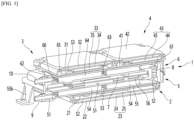
- FIG. 3 is a partial cutaway perspective view of an example of an electronic control unit according to the present invention
- FIG. 4 is an exploded perspective view of an example of a first control unit according to the present invention
- FIG. 5 is an exploded perspective view of the first coolant jacket and second coolant jacket shown in FIG. 4 ;
- the electronic control unit may be installed in a vehicle and may be a control unit for autonomous driving of the vehicle.
- the electronic control unit may be connected to a cooling device installed in the vehicle and may be cooled by coolant circulated by the cooling device.
- the electronic control unit may comprise at least one control unit. It is possible for the at least one control unit to comprise only one first control unit 1, and it is also possible to further comprise at least one extended control unit in addition to the first control unit 1.
- the extended control unit may comprise only the second control unit 2 mounted on the first control unit 1, or the extended control unit may comprise the second control unit 2 and the third control unit 3 mounted on the first control unit 1, or the extended control unit may comprise a second control unit 2, a third control unit 3, and a fourth control unit 4 mounted on the first control unit 1.
- the first control unit 1 may be an autonomous driving control unit for executing level 1 or level 2 of the autonomous driving levels.
- the second control unit 2 may be an autonomous driving control unit for executing level 2+ of the autonomous driving levels, or an infotainment control unit capable of executing the vehicle's infotainment (software or media that adds entertainment to the delivery of information).
- the second control unit 2 may be a control unit disposed below the lower surface of the first control unit 1.
- the third control unit 3 may be an autonomous driving control unit for executing level 3 of the autonomous driving levels.
- the third control unit 3 may be a control unit disposed above the upper surface of the first control unit 1.
- the fourth control unit 4 may be an autonomous driving control unit for executing level 4 of the autonomous driving levels.
- the fourth control unit 4 may be a control unit disposed above the upper surface of the first control unit 1 together with the third control unit 3.
- the control board may have semiconductor chips such as MCUs for autonomous driving or infotainment installed on the board.
- a coolant passage capable of cooling the control board disposed in the first control unit 1 may be formed in the first control unit 1, and a coolant passage may not be formed in each of the second control unit 2, the third control unit 3, and the fourth control unit 4, and control boards of the second control unit 2, third control unit 3, and fourth control unit 4 can be cooled by coolant passing through a coolant passage formed in the first control unit 1.
- the first control unit 1 may have a length in the front and rear direction X, a width in the left and right direction Y, and a thickness in the up and down direction Z.
- the first control unit 1 may comprise a first (bottom) coolant jacket 5, a second (top) coolant jacket 6, and a first control board 7.
- the first coolant jacket 5 may be formed with a first passage 51 and a second passage 52 spaced apart from the first passage 51.
- the first coolant jacket 5 may be formed with a first (lower) coolant passage 53 and a plurality of first (lower) cooling fins 54 through which coolant passes between the first passage 51 and the second passage 52.
- the first passage 51 may be formed at one end of the first coolant jacket 5 in the longitudinal direction X.
- the first passage 51 may be open in the longitudinal direction X of the first coolant jacket 5.
- the second passage 52 may be formed close to the other end of the first coolant jacket 5 in the longitudinal direction X.
- the second passage 52 may be open in the thickness direction Z of the first coolant jacket 5.
- the first coolant passage 53 may be formed to be long in the longitudinal direction X of the first coolant jacket 5.
- the plurality of first cooling fins 54 may be disposed in the first coolant passage 53.
- the plurality of first cooling fins 54 may be spaced apart from each other in the width direction Y of the first coolant jacket 5.
- a unit passage through which coolant is distributed may be formed between a pair of adjacent first cooling fins 54.
- the first coolant jacket 5 may be composed of a combination of multiple members.
- the first coolant jacket 5 may comprise a first (bottom) jacket 55 and a first inner cover 56.
- the first passage 51, the second passage 52, the first coolant passage 53, and the plurality of first cooling fins 54 may be formed in the first jacket 55.
- the first jacket 55 may have a first opening 55a formed above the upper side of the first coolant passage 53 to expose the first coolant passage 53 and the plurality of first cooling fins 54.
- the first inner cover 56 may be disposed on the upper surface of the first jacket 55.
- the first inner cover 56 may be disposed in the first opening 55a.
- the first inner cover 56 may cover the first coolant passage 53 and the plurality of first cooling fins 54.
- the first coolant jacket 5 may comprise a plurality of support legs 55b.
- a plurality of support legs 55b may be formed on the first jacket 55 to be spaced apart from each other in the horizontal direction.
- the second coolant jacket 6 may be vertically symmetrical with the first coolant jacket 5 with the first control board 7 interposed therebetween.
- the first control board 7 is disposed between the second coolant jacket 6 and the first coolant jacket 5.
- the second coolant jacket 6 may be formed with a third passage 61 communicating with the second passage 52 and a fourth passage 62 spaced apart from the third passage 61.
- the second coolant jacket 6 may be formed with a second (upper) coolant passage 63 and a plurality of second (upper) cooling fins 64 through which coolant passes between the third passage 61 and the fourth passage 62.
- the third passage 61 may be formed close to the other end of the second coolant jacket 6 in the longitudinal direction X.
- the third passage 61 may be open in the vertical direction Z of the second coolant jacket 6.
- the fourth passage 62 may be formed at one end of the second coolant jacket 6 in the longitudinal direction X.
- the fourth passage 62 may be open in the longitudinal direction X of the second coolant jacket 6.
- the second coolant passage 63 may be formed to be long in the longitudinal direction X of the second coolant jacket 6.
- the plurality of second cooling fins 64 may be located in the second coolant passage 63 and may be formed to be long in the longitudinal direction X of the second coolant jacket 6. The length of the plurality of second cooling fins 64 may be shorter than the length of the second coolant passage 63.
- the plurality of second cooling fins 64 may be disposed in the second coolant passage 63.
- the plurality of second cooling fins 64 may be spaced apart from each other in the width direction Y of the second coolant jacket 6.
- a unit passage through which coolant is distributed may be formed between a pair of adjacent second cooling fins 64.
- the second coolant jacket 6 may be composed of a combination of multiple members.
- the second coolant jacket 6 may comprise a second (top) jacket 65 and a second inner cover 66.
- the third passage 61, the fourth passage 62, the second coolant passage 63, and the plurality of second cooling fins 64 may be formed in the second jacket 65.
- the second jacket 65 may be formed with an upper opening 65a formed below the lower side of the second coolant passage 63 to expose the second coolant passage 63 and the plurality of second cooling fins 64.
- the second inner cover 66 may be placed on the lower surface of the second jacket 65.
- the second inner cover 66 may be disposed in the upper opening 65a.
- the second inner cover 66 may cover the second coolant passage 63 and the plurality of second cooling fins 64.
- the first coolant jacket 5 and the second coolant jacket 6 may be fastened with a fastening member such as a screw.
- a space S1 in which the first control board 7 can be accommodated may be formed between the first coolant jacket 5 and the second coolant jacket 6.
- the first control board 7 may be disposed between the first coolant jacket 5 and the second coolant jacket 6.
- the first control board 7 may be accommodated in the space S1 formed between the first coolant jacket 5 and the second coolant jacket 6.
- the first control board 7 may comprise a substrate 71 and a semiconductor chip 72 installed on the substrate 71.
- An example of the semiconductor chip 72 may be to execute level 1 or level 2 among the autonomous driving levels and may be an autonomous driving chip such as an MCU.
- the first control board 7 may be in thermal contact with each of the first coolant jacket 5 and the second coolant jacket 6.
- the lower surface of the substrate 71 or the semiconductor chip 72 protruding from the lower surface of the substrate 71 may be in thermal contact with the first coolant jacket 5, particularly the first inner cover 56.
- the upper surface of the substrate 71 or the semiconductor chip 72 protruding from the upper surface of the substrate 71 may be in thermal contact with the second coolant jacket 6, particularly the second inner cover 66.
- a groove 73 may be formed in the first control board 7 to avoid at least one of the second passage 52 and the third passage 61.
- the first control unit 1 may further comprise an inner gasket 8 that seals between the second passage 52 and the third passage 61.
- the lower portion of the inner gasket 8 may be inserted into the second passage 52, the upper portion may be inserted into the third passage 61, and the protrusion formed at the center of the inner gasket 8 is placed between the first coolant jacket 5 and the second coolant jacket 6.
- the coolant may pass through the first coolant passage 53, the coolant may cool the lower surface of the first control board 7, and the coolant sequentially passes through the second passage 52, the inside of the inner gasket 8, and the third passage 61.
- the Coolant may pass through the second coolant passage 63, and the coolant may cool the upper surface of the first control board 7 while passing through the second coolant passage 63.
- the coolant may pass through the second coolant passage 63, and the coolant may cool the upper surface of the first control board 7, and the coolant sequentially passes through the third passage 61, the inside of the inner gasket 8, and the second passage 52.
- the Coolant may pass through the first coolant passage 53, and the coolant may cool the lower surface of the first control board 7 while passing through the first coolant passage 53.
- the first control unit 1 may comprise a first nipple 9 disposed in the first passage 51; and a second nipple 10 disposed in the fourth passage 62.
- a portion of the first nipple 9 may be inserted into the first passage 51.
- a portion of the second nipple 10 may be inserted into the fourth passage 62.
- the second control unit 2 may be parallel to the first control unit 1.
- the second control unit 2 may have a length in the front and rear direction X, a width in the left and right direction Y, and a thickness in the up and down direction Z.
- the second control unit 2 may be disposed below the lower surface of the first coolant jacket 3.
- the second control unit 2 may be coupled to a side portion of the first coolant jacket 5 in the manner that the first coolant jacket 5 is disposed between the first control board 7 and the second control unit 2.
- the second control unit 2 may comprise a first lower case 21, a second lower case 22, and a second control board 23.
- a coolant passage is not formed in the second control unit 2, and the second control unit 2 may be disposed below the lower surface of the first coolant jacket 5, and the second control unit 2 may be cooled by the coolant passing through the first coolant passage 53.
- the first lower case 21 may be disposed below the lower surface of the first coolant jacket 5.
- the second lower case 22 may be disposed below the first lower case 21.
- the second lower case 22 may be fastened to the first lower case 21 using a fastening member such as a screw.
- the second control board 23 may be accommodated between the first lower case 21 and the second lower case 22.
- a space S2 in which the second control board 23 can be accommodated may be formed between the first lower case 21 and the second lower case 22.
- the second control board 23 may comprise a substrate 24 and a semiconductor chip 25 installed on the substrate 24.
- An example of the semiconductor chip 25 may be capable of executing level 2+ among autonomous driving levels and may be an autonomous driving chip such as an MCU.
- Another example of the semiconductor chip 25 may be capable of executing infotainment and may be an infotainment chip such as an MCU.
- the second control board 23 may be in thermally contact with the first coolant jacket 5.
- the upper surface of the substrate 24 or the semiconductor chip 25 protruding from the upper surface of the substrate 24 may be thermally contacted with the coolant passing through the first coolant passage 53 through the first lower case 21 and the first jacket 55.
- the electronic control unit may further comprise a first thermal pad 26 disposed between the first coolant jacket 5 and the upper surface of the second control unit 2.
- the first thermal pad 26 may be disposed between the lower surface of the first coolant jacket 5 and the upper surface of the first lower case 21.
- the electronic control unit further comprises a first thermal pad 26, the upper surface of the substrate 24 or the semiconductor chip 25 protruding on the upper surface of the substrate 24 may be thermally contacted with the coolant passing through the first coolant passage 53 through the first lower case 21, the first thermal pad 26 and the first jacket 55.
- the third control unit 3 may be parallel to the first control unit 1.
- the third control unit 3 may have a length in the front and rear direction X, a width in the left and right direction Y, and a thickness in the up and down direction Z.
- the third control unit 3 may be disposed above the upper surface of the second coolant jacket 6.
- the third control unit 3 may be coupled to a side portion of the second coolant jacket 6 in the manner that the second coolant jacket 6 is disposed between the first control board 7 and the third control unit 3.
- the size of the third control unit 3 may be smaller than the size of the first control unit 1.
- the third control unit 3 comprises a first case 31 and a second case 32; and a third control board 33.
- a coolant passage is not formed in the third control unit 3, and the third control unit 3 can be disposed above the upper surface of the second coolant jacket 6, and the third control unit 3 may be cooled by the coolant passing through the second coolant passage 63.
- the first case 31 may be coupled to a surface of the second coolant jacket 6. Specifically, the first case 31 may be disposed above the upper surface of the second coolant jacket 6.
- the second case 32 may be displaced apart from or above the first case 31.
- the second case 32 may be fastened to the first case 31 using a fastening member such as a screw.
- the third control board 33 may be accommodated between the first case 31 and the second case 32 of the third control unit 3.
- a space S3 in which the third control board 33 can be accommodated may be formed between the first case 31 and the second case 32.
- the third control board 33 may comprise a substrate 34 and a semiconductor chip 35 installed on the substrate 34, and an example of the semiconductor chip 35 is capable of executing level 3 of the autonomous driving levels and may be an autonomous driving chip such as an MCU.
- the third control board 33 may be in thermally contact with the second coolant jacket 6.
- the lower surface of the substrate 34 or the semiconductor chip 35 protruding from the lower surface of the substrate 34 may be thermally contacted with the coolant passing through the second coolant passage 63 through the first case 31 and the second jacket 65.
- the electronic control unit may comprise a second thermal pad 36 disposed between the upper surface of the second coolant jacket 6 and the lower surface of the third control unit 3.
- the second thermal pad 36 may be disposed between the upper surface of the second coolant jacket 6 and the first case 31 of the third control unit 3.
- the electronic control unit further comprises a first upper thermal pad 36, the lower surface of the substrate 34 or the semiconductor chip 35 protruding from the lower surface of the substrate 34 may be in thermally contact with the coolant passing through the second coolant passage 63 through the first case 31, the upper thermal pad 36 and the second jacket 65.
- the fourth control unit 4 may be parallel to the first control unit 1.
- the fourth control unit 4 may have a length in the front and rear direction X, a width in the left and right direction Y, and a thickness in the up and down direction Z.
- the size of the fourth control unit 4 may be smaller than the size of the first control unit 1.
- the fourth control unit 4 may be disposed above the upper surface of the second coolant jacket 6.
- the fourth control unit 4 may be coupled to another side portion of the second coolant jacket 6 in the manner that the second coolant jacket 6 is disposed between the first control board 7 and the fourth control unit 4.
- the fourth control unit 4 comprises a third case 41 and a fourth case 42; and a fourth control board 43.
- a coolant passage is not formed in the fourth control unit 4, and the fourth control unit 4 may be disposed above the upper surface of the second coolant jacket 6, and may be cooled by the coolant passing through the second coolant passage 63.
- the third case 41 may be coupled to said side portion of the second coolant jacket 6. Specifically, the third case 41 may be disposed above the upper surface of the second coolant jacket 6.
- the fourth case 42 may be placed apart from or above the third case 41.
- the fourth case 42 may be fastened to the third case 41 using a fastening member such as a screw.
- the fourth control board 43 may be accommodated between the third case 41 and the fourth case 42 of the fourth control unit 4.
- a space S4 in which the fourth control board 43 can be accommodated may be formed between the third case 41 and the fourth case 42.
- the fourth control board 43 may comprise a substrate 44 and a semiconductor chip 45 installed on the substrate 44, and an example of the semiconductor chip 45 is capable of executing level 4 of the autonomous driving levels and may be an autonomous driving chip such as an MCU.
- the fourth control board 43 may be in thermally contact with the second coolant jacket 6.
- the lower surface of the substrate 44 or the semiconductor chip 45 protruding from the lower surface of the substrate 44 may be thermally contacted with the coolant passing through the second coolant passage 63 through the third case 41 and the second jacket 65.
- the electronic control unit may further comprise a third thermal pad 46 disposed between the upper surface of the second coolant jacket 6 and the lower surface of the fourth control unit 4.
- the third thermal pad 46 may be disposed between the upper surface of the second coolant jacket 6 and the third case 41 of the third control unit.
- the electronic control unit further comprises a third thermal pad 46, the lower surface of the substrate 44 or the semiconductor chip 45 protruding from the lower surface of the substrate 44 may be in thermally contact with the coolant passing through the second coolant passage 63 through the third case 41, the third thermal pad 46 and the second jacket 65.
- the third control unit 3 and the fourth control unit 4 may be disposed in line in the longitudinal direction X of the first control unit 1.
- the third control unit 3 may be disposed closer to the fourth passage 62 than to the third passage 61.
- the fourth control unit 4 may be disposed closer to the third passage 61 than to the fourth passage 62.
- An example of an electronic control unit comprises all of the first control unit 1, the second control unit 2, the third control unit 3, and the fourth control unit 4, and the semiconductor chips of the first control board 7, the second control board 23, the third control board 33, and the fourth control board 43 may be driven together for level 4 autonomous driving.
- the first control board 7, the third control board 33, and the fourth control board 43 may be a higher heat source than the second control board 23, and as shown in Figure 1 , it is preferable that the coolant may be supplied to the electronic control unit through the second nipple 10.
- FIG. 6 is a perspective view of another example of an electronic control unit according to the present invention.
- FIG. 6 Another example of an electronic control unit, as shown in FIG. 6 , does not comprise a fourth control unit 4, but comprises the first control unit 1, the second control unit 2, and the third control unit 3.
- Each semiconductor chips of the first control board 7, the second control board 23, and the third control board 33, respectively, may be driven together for level 3 autonomous driving.
- the first control board 7 and the third control board 33 may be a higher heat source than the second control board 23, and as shown in FIG. 6 , it is preferable that the coolant may be supplied to the electronic control unit through the nipple 10.
- FIG. 7 is a perspective view of the other example of an electronic control unit according to the present invention.
- the other example of the electronic control unit is as shown in Figure 7 , the electronic control unit does not comprise the third control unit 3 and the fourth control unit 4, but comprises the first control unit 1 and the second control unit 2.
- Each semiconductor chip of the first control board 7 and the second control board 23 can be driven for level 1, level 2, or level 2+ autonomous driving.
- the coolant may be supplied through the first nipple 9 so that each of the first control board 7 and the second control board 23 can be cooled quickly.
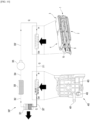
- FIG. 8 shows an operation mode of a cooling device connected to the electronic control unit according to the present invention
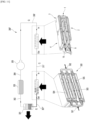
- FIG. 9 shows another operation mode of the cooling device shown in Fig. 8 .
- the cooling device 300 may be installed in the vehicle and may circulate and supply coolant to the electronic control unit installed in the vehicle.
- the cooling device 300 may be connected to the electronic control unit with a water pipe.
- the cooling device 300 comprises a heat exchanger 301, a coolant tank 303 connected to the heat exchanger 301 via a heat exchanger outlet pipe 302, a pump 305 connected to the coolant tank 303 via the pump inlet pipe 304 and a pump outlet pipe 306 connecting the pump 305 and the electronic control unit, and the electronic control unit and the heat exchanger 301 may be connected to a heat exchanger inlet pipe 307.
- the heat exchanger 301 may dissipate heat from the coolant into the atmosphere in an air-cooled manner.
- the cooling device 300 may comprise a cooling water valve 308.
- the coolant valve 308 may supply coolant to the second nipple 10. As shown in FIG. 9 , the coolant valve 308 may supply coolant to the first nipple 9.
- An example of the coolant valve 308 may be a four-way valve.
- the pump outlet pipe 306 may be connected to the cooling water valve 308.
- the heat exchanger inlet pipe 307 may be connected to the cooling water valve 308.
- the coolant valve 308 and the first nipple 9 may be connected to a first nipple connection pipe 309.
- the coolant valve 308 and the second nipple 10 may be connected to the second nipple connection pipe 310.
- the coolant valve 308 may be switched to supply the coolant to the second nipple 10
- the coolant valve 808 may be switched to supply the coolant to the first nipple 9.
- the coolant may circulate through the heat exchanger 301 and the electronic control unit and dissipate heat in the electronic control unit.
- FIG. 10 shows another cooling device connected to the electronic control unit of the present invention and a vehicle motor 400.
- the cooling device 300' may circulate cold cooling water through the electronic control unit and the motor 400.
- An example of the motor 400 may be a drive motor provided in an electric vehicle to provide driving force to the wheels.
- the motor 400 may comprise a motor housing 403 in which a coolant inlet port 401 and a coolant outlet port 402 are formed.
- the cooling device 300' may be connected to the electronic control unit and motor 400 through a water pipe.
- the cooling device 300' may comprise a heat exchanger 301, a coolant tank 303 connected to the heat exchanger 301 via a heat exchanger outlet pipe 302, a pump 305 connected to the coolant tank 303 via a pump inlet pipe 304, a pump outlet pipe 306' connecting the pump 305 and the electronic control unit, a connection passage 311 connecting the electronic control unit and the motor 400, and a heat exchanger inlet pipe 307' connected to the motor 400 and the heat exchanger 301.
- the heat exchanger 301, the heat exchanger outlet pipe 302, the cooling water tank 303, the pump inlet pipe 304, and the pump 305 are the same as the cooling device 300 shown in FIG. 9 , their descriptions will be omitted to avoid redundant explanation.
- the pump outlet pipe 306' may be connected to either the first nipple 9 or the second nipple 10.
- the heat exchanger inlet pipe 307' may be connected to the coolant outlet port 402 of the motor 400.
- connection passage 311 may be connected to the other one of the first nipple 9 or the second nipple 10.
- connection passage 311 may be connected to the coolant inlet port 401 of the motor 400.
- the coolant may circulate through the heat exchanger 301, the electronic control unit, and the motor 400, and may sequentially dissipate heat through the electronic control unit and the motor 400.
- FIG. 11 shows another cooling device connected to the electronic control unit of the present invention and an additional electronic control unit 500.
- the cooling device 300" may circulate cold cooling water to the electronic control unit of the present invention and the additional electronic control unit 500.
- the additional electronic control unit 500 may comprise an additional coolant jacket in which a coolant inlet 501 and a coolant outlet 502 are formed.
- An example of the additional electronic control unit 500 may be an electronic control unit provided separately from the electronic control unit of the present invention, and may comprise a plurality of additional coolant jackets 503, 504, and 505.
- the plurality of additional coolant jackets 503, 504, and 505 may be configured to have coolant flow paths connected in parallel.
- the cooling device 300" may be connected to the electronic control unit of the present invention and the additional electronic control unit 500 through a water pipe.
- the cooling device 300" may comprise a heat exchanger 301, a cooling water tank 303 connected to the heat exchanger 301 via the heat exchanger outlet pipe 302, a pump 305 connected to the cooling water tank 303 via the pump inlet pipe 304, a pump outlet pipe 306' connecting the pump 305 and the electronic control unit, a connection passage 311' connecting the electronic control unit and the additional electronic control unit 500, and a heat exchanger inlet pipe 307" connecting the additional electronic control unit 500 and the heat exchanger 301.
- the heat exchanger 301, the heat exchanger outlet pipe 302, the cooling water tank 303, the pump inlet pipe 304, the pump 305, and the pump outlet pipe 306' are the same as the cooling device 300' shown in FIG. 10 , their description will be omitted to avoid redundant explanation.
- the pump outlet pipe 306' may be connected to either the first nipple 9 or the second nipple 10.
- connection passage 311' may be connected to the other one of the first nipple 9 and the second nipple 10.
- connection passage 311' may be connected to the coolant inlet 501 of the additional electronic control unit 500.
- the heat exchanger inlet pipe 307" may be connected to the coolant outlet 502 of the additional electronic control unit 500.
- the coolant may circulate through the heat exchanger 301, the electronic control unit, and the additional electronic control unit 500, and may sequentially dissipate heat through the electronic control unit and the additional electronic control unit 500.
- the coolant may flow through the passage at a specific flow rate Q by the pump 305, and the coolant may flow into the electronic control unit, cool the heat source of the electronic control unit, and then flow out of the electronic control unit.
- the coolant flowing out of the electronic control unit may flow to the additional electronic control unit 500 to cool the heat source of the additional electronic control unit 500 and then may pass through the heat exchanger 301 to return to an initial temperature, and the coolant whose temperature has been initialized flows into the coolant tank 303.
- the above process may be repeated for the coolant stored in the coolant tank 303.
- the cooling devices shown in Figs. 8 to 11 are just exemplary devices for supplying coolant to the electronic control unit of the present invention, but different types of cooling devices can be adopted by a person skilled in the technology of refrigeration cycle.
- the coolant sequentially passing through the first (lower) coolant passage and the second (upper) coolant passage can cool the lower and upper surfaces of the first control board, and both sides of the first control board can be quickly cooled with a simple structure.
- the coolant passing through the first coolant passage can cool the first control board and the second control board together, and the first coolant passage can also serve as the coolant passage of the first control board and the coolant passage of the second control board, the structure is simple and compactization is possible.
- the coolant passing through the second coolant passage can cool the first control board and the third control board together, and the second coolant passage can also serve as the coolant passage of the first control board and the coolant passage of the third control board. the structure is simple and compactization is possible.
- the coolant passing through the second coolant passage can cool the first control board, the third control board, and the fourth control board together, and the second coolant passage is the coolant passage of the first control board and the coolant passage of the third control board and a coolant passage for the fourth control board, the structure is simple and compactization is possible.
- the electronic control unit may comprise a first control unit and a second control unit, or may comprise a first control unit, a second control unit and a third control unit, or may comprise a first control unit, a second control unit and a third control unit. unit and a fourth control unit, so the electronic control unit can be expanded depending on the vehicle.
- the coolant valve can allow the coolant to pass through the first coolant passage first or the second coolant passage first, allowing the coolant to cool the control board of the high heat source more quickly.
Landscapes
- Engineering & Computer Science (AREA)
- Microelectronics & Electronic Packaging (AREA)
- Physics & Mathematics (AREA)
- Thermal Sciences (AREA)
- Cooling Or The Like Of Semiconductors Or Solid State Devices (AREA)
- Cooling Or The Like Of Electrical Apparatus (AREA)
- Mechanical Engineering (AREA)
Abstract
The electronic control unit according to this embodiment comprises a first control unit, and the first control unit comprises a first coolant jacket in which a first passage and a second passage spaced apart from the first passage are formed; and a second coolant jacket in which a third passage communicate with the second passage and a fourth passage spaced apart from the third passage are formed. A first coolant passage through which coolant passes may be formed between the first passage and the second passage and a plurality of first cooling fins may be formed in a first coolant passage. A second coolant passage through which coolant passes may be formed between the third passage and the fourth passage and a plurality of second cooling fins may be formed in the second coolant passage. A first control board may be disposed between the first coolant jacket and the second coolant jacket.
Description
- The present invention relates to an electronic control unit, particularly suitable for a vehicle. The electronic control unit of the present invention includes at least one coolant flow passage for cooling of electronic devices in the electronic control unit.
- Assemblies installed in a vehicle comprise an engine control assembly (or motor control assembly), power transmission assembly, brake assembly, suspension assembly, steering assembly, instrument assembly, and information and communication control assembly.
- An electronic control unit (ECU) is a control device that has the function of controlling and managing the main assemblies of a vehicle. A number of electronic control units are installed in the vehicle depending on the assembly to control each assembly.
- The electronic control unit may comprise an electronic control unit with a built-in chip for autonomous driving or infotainment (software or media that adds entertainment to the transfer of information) installed in the vehicle, and it is desirable for the chip or the board (control board) on which the chip is installed to be properly cooled to prevent overheating of the chip.
- An example of an electronic control unit being cooled is an electronic module disclosed in U.S. Patent Publication No.
US 5323292 A (Patent, on June 21, 1994 ). The electronic module comprises an aluminum heat sink surrounding an integrated circuit chip and a substrate, and the aluminum heat sink comprises parallel fins that provide a larger surface area to dissipate heat into the surrounding atmosphere. - The present embodiment to provide an electronic control unit in which both sides of a control board can be cooled.
- The electronic control unit according to this embodiment comprises a first control unit. The first control unit comprises a first coolant jacket including a first passage located at an end portion of the first coolant jacket, and a second passage located at the other end portion of the first coolant jacket and communicating with the first passage; a second coolant jacket including a third passage located at an end portion of the second coolant jacket and communicating with the second passage, and a fourth passage spaced located at the other end portion of the second coolant jacket and communicating with the third passage; and a first control board disposed between the first coolant jacket and the second coolant jacket. A first coolant passage through which coolant flows may be formed between the first passage and the second passage, and a plurality of first cooling fins may be formed in the first coolant passage. A second coolant passage through which coolant flows may be formed between the third passage and the fourth passage, and a plurality of second cooling fins may be formed in the second coolant passage. The coolant may be water but different kinds of coolant may be used instead of water.
- The first coolant jacket may comprise a first jacket formed with the first passage, the second passage, the first coolant passage, and the plurality of first cooling fins; and a first inner cover disposed on a first surface of the first jacket facing the first control board and covering the first coolant passage and the plurality of first cooling fins.
- The second coolant jacket may comprise a second jacket formed with the third passage, the fourth passage, the second coolant passage, and the plurality of second cooling fins, and a second inner cover disposed on a first surface of the second jacket facing the first control board and covering the second coolant passage and the plurality of second cooling fins.
- The first control unit may further comprise an inner gasket sealing between the second passage and the third passage.
- The electronic control unit may further comprise a second control unit coupled to a side portion of the first coolant jacket in the manner that the first coolant jacket is disposed between the first control board and the second control unit.
- The second control unit may comprise a first case coupled to a surface of the first coolant jacket; a second case spaced apart from the first lower case; and a second control board accommodated between the first case and the second case of the second control unit.
- The electronic control unit may further comprise a first thermal pad disposed between the first coolant jacket and the first case of the second control unit.
- The electronic control unit may further comprise a third control unit coupled to a side portion of the second coolant jacket in the manner that the second coolant jacket is disposed between the first control board and the third control unit.
- The third control unit may comprise a first case coupled to a surface of the second coolant jacket; a second case spaced apart from the first case; and a third control board accommodated between the first case and the second case of the third control unit.
- The electronic control unit may further comprise a second thermal pad disposed between the second coolant jacket and the first case of the third control unit.
- The electronic control unit may further comprise a fourth control unit coupled to another side portion of the second coolant jacket in the manner that the second coolant jacket is disposed between the first control board and the fourth control unit.
- The fourth control unit may comprise a third case coupled to said side portion of the second coolant jacket; a fourth case spaced apart from the third case; and a fourth control board accommodated between the third case and the fourth case of the fourth control unit.
- The electronic control unit may further comprise a third thermal pad disposed between the second coolant jacket and the third case of the fourth control unit.
- The fourth control unit may be disposed in line with the third control unit in the longitudinal direction of the first control unit.
- The third control unit may be disposed closer to the fourth passage than to the third passage, and the fourth control unit may be disposed closer to the third passage than to the fourth passage.
- A vehicle according to this embodiment comprises an electronic control unit comprising a first control unit; and a cooling device flowing coolant to the first control unit.
- The electronic control unit according to this embodiment comprises a first control unit, and the first control unit comprises a first coolant jacket in which a first passage and a second passage spaced apart from the first passage are formed; a second coolant jacket in which a third passage communicate with the second passage and a fourth passage spaced apart from the third passage are formed, a first nipple disposed in the first passage; and a second nipple disposed in the fourth passage. A first coolant passage through which coolant passes may be formed between the first passage and the second passage, and a plurality of first cooling fins may be formed in the first coolant passage. A second coolant passage through which coolant passes may be formed between the third passage and the fourth passage, and a plurality of second cooling fins may be formed in the second coolant passage. A first control board may be disposed between the first coolant jacket and the second coolant jacket.
- The cooling device may comprise a coolant valve suppling coolant to the first nipple or to the second nipple.
- The vehicle may further comprise a second control unit disposed below a lower surface of the first coolant jacket and the coolant valve supplies coolant to the first nipple.
- The vehicle may further comprise a second control unit disposed below a lower surface of the first coolant jacket; and a third control unit disposed above an upper surface of the second coolant jacket, the coolant valve supplies coolant to the second nipple.
- The vehicle may further comprise a fourth control unit disposed above the upper surface of the second coolant jacket.
- The third control unit may be closer to the fourth passage than to the third passage, and the fourth control unit may be closer to the third passage than to the fourth passage.
-
-
FIG. 1 is a perspective view of an example of an electronic control unit according to the present invention; -
FIG. 2 is an exploded perspective view of an example of an electronic control unit according to the present invention; -
FIG. 3 is a partial cutaway perspective view of an example of an electronic control unit according to the present invention; -
FIG. 4 is an exploded perspective view of an example of a first control unit according to the present invention; -
FIG. 5 is an exploded perspective view of the first coolant jacket and second coolant jacket shown inFIG. 4 ; -
FIG. 6 is a perspective view of another example of an electronic control unit according to the present invention; -
FIG. 7 is a perspective view of the other example of an electronic control unit according to the present invention; -
FIG. 8 shows an operation mode of a cooling device connected to the electronic control unit according to the present invention; -
FIG. 9 shows another operation mode of the cooling device ofFig. 8 ; -
FIG. 10 shows another cooling device connected to the electronic control unit of the present invention and a vehicle motor; and -
FIG. 11 shows another cooling device connected to the electronic control unit of the present invention and an additional electronic control unit. - Hereinafter, detailed embodiments will be described in detail with reference to the accompanying drawings.
-
FIG. 1 is a perspective view of an example of an electronic control unit according to the present invention;FIG. 2 is an exploded perspective view of an example of an electronic control unit according to the present invention;FIG. 3 is a partial cutaway perspective view of an example of an electronic control unit according to the present invention;FIG. 4 is an exploded perspective view of an example of a first control unit according to the present invention; andFIG. 5 is an exploded perspective view of the first coolant jacket and second coolant jacket shown inFIG. 4 ; - The electronic control unit may be installed in a vehicle and may be a control unit for autonomous driving of the vehicle.
- The electronic control unit may be connected to a cooling device installed in the vehicle and may be cooled by coolant circulated by the cooling device.
- The electronic control unit may comprise at least one control unit. It is possible for the at least one control unit to comprise only one
first control unit 1, and it is also possible to further comprise at least one extended control unit in addition to thefirst control unit 1. - When the electronic control unit further comprises an extended control unit, the extended control unit may comprise only the
second control unit 2 mounted on thefirst control unit 1, or the extended control unit may comprise thesecond control unit 2 and thethird control unit 3 mounted on thefirst control unit 1, or the extended control unit may comprise asecond control unit 2, athird control unit 3, and a fourth control unit 4 mounted on thefirst control unit 1. - The
first control unit 1 may be an autonomous driving control unit for executinglevel 1 orlevel 2 of the autonomous driving levels. - The
second control unit 2 may be an autonomous driving control unit for executinglevel 2+ of the autonomous driving levels, or an infotainment control unit capable of executing the vehicle's infotainment (software or media that adds entertainment to the delivery of information). - The
second control unit 2 may be a control unit disposed below the lower surface of thefirst control unit 1. - The
third control unit 3 may be an autonomous driving control unit for executinglevel 3 of the autonomous driving levels. - The
third control unit 3 may be a control unit disposed above the upper surface of thefirst control unit 1. - The fourth control unit 4 may be an autonomous driving control unit for executing level 4 of the autonomous driving levels.
- The fourth control unit 4 may be a control unit disposed above the upper surface of the
first control unit 1 together with thethird control unit 3. - Each of the
first control unit 1, thesecond control unit 2, thethird control unit 3, and the fourth control unit 4 may comprise a control board. - The control board may have semiconductor chips such as MCUs for autonomous driving or infotainment installed on the board.
- A coolant passage capable of cooling the control board disposed in the
first control unit 1 may be formed in thefirst control unit 1, and a coolant passage may not be formed in each of thesecond control unit 2, thethird control unit 3, and the fourth control unit 4, and control boards of thesecond control unit 2,third control unit 3, and fourth control unit 4 can be cooled by coolant passing through a coolant passage formed in thefirst control unit 1. - Hereinafter, each control unit will be described.
- The
first control unit 1 may have a length in the front and rear direction X, a width in the left and right direction Y, and a thickness in the up and down direction Z. - The
first control unit 1 may comprise a first (bottom)coolant jacket 5, a second (top)coolant jacket 6, and afirst control board 7. - The
first coolant jacket 5 may be formed with afirst passage 51 and asecond passage 52 spaced apart from thefirst passage 51. - The
first coolant jacket 5 may be formed with a first (lower)coolant passage 53 and a plurality of first (lower) coolingfins 54 through which coolant passes between thefirst passage 51 and thesecond passage 52. - The
first passage 51 may be formed at one end of thefirst coolant jacket 5 in the longitudinal direction X. Thefirst passage 51 may be open in the longitudinal direction X of thefirst coolant jacket 5. - The
second passage 52 may be formed close to the other end of thefirst coolant jacket 5 in the longitudinal direction X. Thesecond passage 52 may be open in the thickness direction Z of thefirst coolant jacket 5. - The
first coolant passage 53 may be formed to be long in the longitudinal direction X of thefirst coolant jacket 5. - The plurality of
first cooling fins 54 may be located in thefirst coolant passage 53 and may be formed to be long in the longitudinal direction X of thefirst coolant jacket 5. The length of the plurality offirst cooling fins 54 may be shorter than the length of thefirst coolant passage 53. - The plurality of
first cooling fins 54 may be disposed in thefirst coolant passage 53. The plurality offirst cooling fins 54 may be spaced apart from each other in the width direction Y of thefirst coolant jacket 5. A unit passage through which coolant is distributed may be formed between a pair of adjacentfirst cooling fins 54. - The
first coolant jacket 5 may be composed of a combination of multiple members. Thefirst coolant jacket 5 may comprise a first (bottom)jacket 55 and a firstinner cover 56. - The
first passage 51, thesecond passage 52, thefirst coolant passage 53, and the plurality offirst cooling fins 54 may be formed in thefirst jacket 55. - The
first jacket 55 may have afirst opening 55a formed above the upper side of thefirst coolant passage 53 to expose thefirst coolant passage 53 and the plurality offirst cooling fins 54. - The first
inner cover 56 may be disposed on the upper surface of thefirst jacket 55. The firstinner cover 56 may be disposed in thefirst opening 55a. The firstinner cover 56 may cover thefirst coolant passage 53 and the plurality offirst cooling fins 54. - The
first coolant jacket 5 may comprise a plurality ofsupport legs 55b. - A plurality of
support legs 55b may be formed on thefirst jacket 55 to be spaced apart from each other in the horizontal direction. - The
second coolant jacket 6 may be vertically symmetrical with thefirst coolant jacket 5 with thefirst control board 7 interposed therebetween. Thefirst control board 7 is disposed between thesecond coolant jacket 6 and thefirst coolant jacket 5. - The
second coolant jacket 6 may be formed with athird passage 61 communicating with thesecond passage 52 and afourth passage 62 spaced apart from thethird passage 61. - The
second coolant jacket 6 may be formed with a second (upper)coolant passage 63 and a plurality of second (upper) coolingfins 64 through which coolant passes between thethird passage 61 and thefourth passage 62. - The
third passage 61 may be formed close to the other end of thesecond coolant jacket 6 in the longitudinal direction X. Thethird passage 61 may be open in the vertical direction Z of thesecond coolant jacket 6. - The
fourth passage 62 may be formed at one end of thesecond coolant jacket 6 in the longitudinal direction X. Thefourth passage 62 may be open in the longitudinal direction X of thesecond coolant jacket 6. - The
second coolant passage 63 may be formed to be long in the longitudinal direction X of thesecond coolant jacket 6. - The plurality of
second cooling fins 64 may be located in thesecond coolant passage 63 and may be formed to be long in the longitudinal direction X of thesecond coolant jacket 6. The length of the plurality ofsecond cooling fins 64 may be shorter than the length of thesecond coolant passage 63. - The plurality of
second cooling fins 64 may be disposed in thesecond coolant passage 63. The plurality ofsecond cooling fins 64 may be spaced apart from each other in the width direction Y of thesecond coolant jacket 6. A unit passage through which coolant is distributed may be formed between a pair of adjacentsecond cooling fins 64. - The
second coolant jacket 6 may be composed of a combination of multiple members. Thesecond coolant jacket 6 may comprise a second (top)jacket 65 and a secondinner cover 66. - The
third passage 61, thefourth passage 62, thesecond coolant passage 63, and the plurality ofsecond cooling fins 64 may be formed in thesecond jacket 65. - The
second jacket 65 may be formed with anupper opening 65a formed below the lower side of thesecond coolant passage 63 to expose thesecond coolant passage 63 and the plurality ofsecond cooling fins 64. - The second
inner cover 66 may be placed on the lower surface of thesecond jacket 65. The secondinner cover 66 may be disposed in theupper opening 65a. The secondinner cover 66 may cover thesecond coolant passage 63 and the plurality ofsecond cooling fins 64. - The
first coolant jacket 5 and thesecond coolant jacket 6 may be fastened with a fastening member such as a screw. - A space S1 in which the
first control board 7 can be accommodated may be formed between thefirst coolant jacket 5 and thesecond coolant jacket 6. - The
first control board 7 may be disposed between thefirst coolant jacket 5 and thesecond coolant jacket 6. Thefirst control board 7 may be accommodated in the space S1 formed between thefirst coolant jacket 5 and thesecond coolant jacket 6. - The
first control board 7 may comprise asubstrate 71 and asemiconductor chip 72 installed on thesubstrate 71. An example of thesemiconductor chip 72 may be to executelevel 1 orlevel 2 among the autonomous driving levels and may be an autonomous driving chip such as an MCU. - The
first control board 7 may be in thermal contact with each of thefirst coolant jacket 5 and thesecond coolant jacket 6. - The lower surface of the
substrate 71 or thesemiconductor chip 72 protruding from the lower surface of thesubstrate 71 may be in thermal contact with thefirst coolant jacket 5, particularly the firstinner cover 56. - The upper surface of the
substrate 71 or thesemiconductor chip 72 protruding from the upper surface of thesubstrate 71 may be in thermal contact with thesecond coolant jacket 6, particularly the secondinner cover 66. - A
groove 73 may be formed in thefirst control board 7 to avoid at least one of thesecond passage 52 and thethird passage 61. - The
first control unit 1 may further comprise aninner gasket 8 that seals between thesecond passage 52 and thethird passage 61. - The lower portion of the
inner gasket 8 may be inserted into thesecond passage 52, the upper portion may be inserted into thethird passage 61, and the protrusion formed at the center of theinner gasket 8 is placed between thefirst coolant jacket 5 and thesecond coolant jacket 6. - The coolant may pass through the
first coolant passage 53, the coolant may cool the lower surface of thefirst control board 7, and the coolant sequentially passes through thesecond passage 52, the inside of theinner gasket 8, and thethird passage 61. The Coolant may pass through thesecond coolant passage 63, and the coolant may cool the upper surface of thefirst control board 7 while passing through thesecond coolant passage 63. - Contrarily, the coolant may pass through the
second coolant passage 63, and the coolant may cool the upper surface of thefirst control board 7, and the coolant sequentially passes through thethird passage 61, the inside of theinner gasket 8, and thesecond passage 52. The Coolant may pass through thefirst coolant passage 53, and the coolant may cool the lower surface of thefirst control board 7 while passing through thefirst coolant passage 53. - The
first control unit 1 may comprise afirst nipple 9 disposed in thefirst passage 51; and asecond nipple 10 disposed in thefourth passage 62. - A portion of the
first nipple 9 may be inserted into thefirst passage 51. - A portion of the
second nipple 10 may be inserted into thefourth passage 62. - The
second control unit 2 may be parallel to thefirst control unit 1. Thesecond control unit 2 may have a length in the front and rear direction X, a width in the left and right direction Y, and a thickness in the up and down direction Z. - The
second control unit 2 may be disposed below the lower surface of thefirst coolant jacket 3. Thesecond control unit 2 may be coupled to a side portion of thefirst coolant jacket 5 in the manner that thefirst coolant jacket 5 is disposed between thefirst control board 7 and thesecond control unit 2. - The
second control unit 2 may comprise a firstlower case 21, a secondlower case 22, and asecond control board 23. - A coolant passage is not formed in the
second control unit 2, and thesecond control unit 2 may be disposed below the lower surface of thefirst coolant jacket 5, and thesecond control unit 2 may be cooled by the coolant passing through thefirst coolant passage 53. - The first
lower case 21 may be disposed below the lower surface of thefirst coolant jacket 5. - The second
lower case 22 may be disposed below the firstlower case 21. The secondlower case 22 may be fastened to the firstlower case 21 using a fastening member such as a screw. - The
second control board 23 may be accommodated between the firstlower case 21 and the secondlower case 22. - A space S2 in which the
second control board 23 can be accommodated may be formed between the firstlower case 21 and the secondlower case 22. - The
second control board 23 may comprise asubstrate 24 and asemiconductor chip 25 installed on thesubstrate 24. An example of thesemiconductor chip 25 may be capable of executinglevel 2+ among autonomous driving levels and may be an autonomous driving chip such as an MCU. Another example of thesemiconductor chip 25 may be capable of executing infotainment and may be an infotainment chip such as an MCU. - The
second control board 23 may be in thermally contact with thefirst coolant jacket 5. - The upper surface of the
substrate 24 or thesemiconductor chip 25 protruding from the upper surface of thesubstrate 24 may be thermally contacted with the coolant passing through thefirst coolant passage 53 through the firstlower case 21 and thefirst jacket 55. - The electronic control unit may further comprise a first
thermal pad 26 disposed between thefirst coolant jacket 5 and the upper surface of thesecond control unit 2. The firstthermal pad 26 may be disposed between the lower surface of thefirst coolant jacket 5 and the upper surface of the firstlower case 21. - If the electronic control unit further comprises a first
thermal pad 26, the upper surface of thesubstrate 24 or thesemiconductor chip 25 protruding on the upper surface of thesubstrate 24 may be thermally contacted with the coolant passing through thefirst coolant passage 53 through the firstlower case 21, the firstthermal pad 26 and thefirst jacket 55. - The
third control unit 3 may be parallel to thefirst control unit 1. Thethird control unit 3 may have a length in the front and rear direction X, a width in the left and right direction Y, and a thickness in the up and down direction Z. - The
third control unit 3 may be disposed above the upper surface of thesecond coolant jacket 6. Thethird control unit 3 may be coupled to a side portion of thesecond coolant jacket 6 in the manner that thesecond coolant jacket 6 is disposed between thefirst control board 7 and thethird control unit 3. - The size of the
third control unit 3 may be smaller than the size of thefirst control unit 1. - The
third control unit 3 comprises afirst case 31 and asecond case 32; and athird control board 33. - A coolant passage is not formed in the
third control unit 3, and thethird control unit 3 can be disposed above the upper surface of thesecond coolant jacket 6, and thethird control unit 3 may be cooled by the coolant passing through thesecond coolant passage 63. - The
first case 31 may be coupled to a surface of thesecond coolant jacket 6. Specifically, thefirst case 31 may be disposed above the upper surface of thesecond coolant jacket 6. - The
second case 32 may be displaced apart from or above thefirst case 31. - The
second case 32 may be fastened to thefirst case 31 using a fastening member such as a screw. - The
third control board 33 may be accommodated between thefirst case 31 and thesecond case 32 of thethird control unit 3. - A space S3 in which the
third control board 33 can be accommodated may be formed between thefirst case 31 and thesecond case 32. - The
third control board 33 may comprise asubstrate 34 and asemiconductor chip 35 installed on thesubstrate 34, and an example of thesemiconductor chip 35 is capable of executinglevel 3 of the autonomous driving levels and may be an autonomous driving chip such as an MCU. - The
third control board 33 may be in thermally contact with thesecond coolant jacket 6. - The lower surface of the
substrate 34 or thesemiconductor chip 35 protruding from the lower surface of thesubstrate 34 may be thermally contacted with the coolant passing through thesecond coolant passage 63 through thefirst case 31 and thesecond jacket 65. - The electronic control unit may comprise a second
thermal pad 36 disposed between the upper surface of thesecond coolant jacket 6 and the lower surface of thethird control unit 3. The secondthermal pad 36 may be disposed between the upper surface of thesecond coolant jacket 6 and thefirst case 31 of thethird control unit 3. - If the electronic control unit further comprises a first upper
thermal pad 36, the lower surface of thesubstrate 34 or thesemiconductor chip 35 protruding from the lower surface of thesubstrate 34 may be in thermally contact with the coolant passing through thesecond coolant passage 63 through thefirst case 31, the upperthermal pad 36 and thesecond jacket 65. - The fourth control unit 4 may be parallel to the
first control unit 1. The fourth control unit 4 may have a length in the front and rear direction X, a width in the left and right direction Y, and a thickness in the up and down direction Z. - The size of the fourth control unit 4 may be smaller than the size of the
first control unit 1. - The fourth control unit 4 may be disposed above the upper surface of the
second coolant jacket 6. The fourth control unit 4 may be coupled to another side portion of thesecond coolant jacket 6 in the manner that thesecond coolant jacket 6 is disposed between thefirst control board 7 and the fourth control unit 4.The fourth control unit 4 comprises athird case 41 and afourth case 42; and afourth control board 43. - A coolant passage is not formed in the fourth control unit 4, and the fourth control unit 4 may be disposed above the upper surface of the
second coolant jacket 6, and may be cooled by the coolant passing through thesecond coolant passage 63. - The
third case 41 may be coupled to said side portion of thesecond coolant jacket 6. Specifically, thethird case 41 may be disposed above the upper surface of thesecond coolant jacket 6. - The
fourth case 42 may be placed apart from or above thethird case 41. - The
fourth case 42 may be fastened to thethird case 41 using a fastening member such as a screw. - The
fourth control board 43 may be accommodated between thethird case 41 and thefourth case 42 of the fourth control unit 4. - A space S4 in which the
fourth control board 43 can be accommodated may be formed between thethird case 41 and thefourth case 42. - The
fourth control board 43 may comprise asubstrate 44 and asemiconductor chip 45 installed on thesubstrate 44, and an example of thesemiconductor chip 45 is capable of executing level 4 of the autonomous driving levels and may be an autonomous driving chip such as an MCU. - The
fourth control board 43 may be in thermally contact with thesecond coolant jacket 6. - The lower surface of the
substrate 44 or thesemiconductor chip 45 protruding from the lower surface of thesubstrate 44 may be thermally contacted with the coolant passing through thesecond coolant passage 63 through thethird case 41 and thesecond jacket 65. - The electronic control unit may further comprise a third
thermal pad 46 disposed between the upper surface of thesecond coolant jacket 6 and the lower surface of the fourth control unit 4. The thirdthermal pad 46 may be disposed between the upper surface of thesecond coolant jacket 6 and thethird case 41 of the third control unit. - If the electronic control unit further comprises a third
thermal pad 46, the lower surface of thesubstrate 44 or thesemiconductor chip 45 protruding from the lower surface of thesubstrate 44 may be in thermally contact with the coolant passing through thesecond coolant passage 63 through thethird case 41, the thirdthermal pad 46 and thesecond jacket 65. - The
third control unit 3 and the fourth control unit 4 may be disposed in line in the longitudinal direction X of thefirst control unit 1. Thethird control unit 3 may be disposed closer to thefourth passage 62 than to thethird passage 61. The fourth control unit 4 may be disposed closer to thethird passage 61 than to thefourth passage 62. - An example of an electronic control unit comprises all of the
first control unit 1, thesecond control unit 2, thethird control unit 3, and the fourth control unit 4, and the semiconductor chips of thefirst control board 7, thesecond control board 23, thethird control board 33, and thefourth control board 43 may be driven together for level 4 autonomous driving. - In the case of an example of an electronic control unit, the
first control board 7, thethird control board 33, and thefourth control board 43 may be a higher heat source than thesecond control board 23, and as shown inFigure 1 , it is preferable that the coolant may be supplied to the electronic control unit through thesecond nipple 10. -
FIG. 6 is a perspective view of another example of an electronic control unit according to the present invention. - Another example of an electronic control unit, as shown in
FIG. 6 , does not comprise a fourth control unit 4, but comprises thefirst control unit 1, thesecond control unit 2, and thethird control unit 3. Each semiconductor chips of thefirst control board 7, thesecond control board 23, and thethird control board 33, respectively, may be driven together forlevel 3 autonomous driving. - In the case of another example of the electronic control unit, the
first control board 7 and thethird control board 33 may be a higher heat source than thesecond control board 23, and as shown inFIG. 6 , it is preferable that the coolant may be supplied to the electronic control unit through thenipple 10. -
FIG. 7 is a perspective view of the other example of an electronic control unit according to the present invention. - The other example of the electronic control unit is as shown in
Figure 7 , the electronic control unit does not comprise thethird control unit 3 and the fourth control unit 4, but comprises thefirst control unit 1 and thesecond control unit 2. Each semiconductor chip of thefirst control board 7 and thesecond control board 23 can be driven forlevel 1,level 2, orlevel 2+ autonomous driving. - In the case of the other example of the electronic control unit, as shown in
FIG. 7 , it is preferable that the coolant may be supplied through thefirst nipple 9 so that each of thefirst control board 7 and thesecond control board 23 can be cooled quickly. -
FIG. 8 shows an operation mode of a cooling device connected to the electronic control unit according to the present invention; andFIG. 9 shows another operation mode of the cooling device shown inFig. 8 . - The
cooling device 300 may be installed in the vehicle and may circulate and supply coolant to the electronic control unit installed in the vehicle. - The
cooling device 300 may be connected to the electronic control unit with a water pipe. - The
cooling device 300 comprises aheat exchanger 301, acoolant tank 303 connected to theheat exchanger 301 via a heatexchanger outlet pipe 302, apump 305 connected to thecoolant tank 303 via thepump inlet pipe 304 and apump outlet pipe 306 connecting thepump 305 and the electronic control unit, and the electronic control unit and theheat exchanger 301 may be connected to a heatexchanger inlet pipe 307. - The
heat exchanger 301 may dissipate heat from the coolant into the atmosphere in an air-cooled manner. - The
cooling device 300 may comprise a coolingwater valve 308. - As shown in
FIG. 8 , thecoolant valve 308 may supply coolant to thesecond nipple 10. As shown inFIG. 9 , thecoolant valve 308 may supply coolant to thefirst nipple 9. - An example of the
coolant valve 308 may be a four-way valve. - The
pump outlet pipe 306 may be connected to the coolingwater valve 308. - The heat
exchanger inlet pipe 307 may be connected to the coolingwater valve 308. - The
coolant valve 308 and thefirst nipple 9 may be connected to a firstnipple connection pipe 309. - The
coolant valve 308 and thesecond nipple 10 may be connected to the secondnipple connection pipe 310. - As shown in
FIG. 1 , in case where the electronic control unit comprises thefirst control unit 1, thesecond control unit 2, thethird control unit 3 and the fourth control unit 4, or the electronic control unit comprises thefirst control unit 1, thesecond control unit 2, and thethird control unit 3, as shown inFIG. 8 , thecoolant valve 308 may be switched to supply the coolant to thesecond nipple 10 - As shown in
FIG. 7 , in case where the electronic control unit comprises afirst control unit 1 and asecond control unit 2, and the electronic control unit does not comprise athird control unit 3 and a fourth control unit 4, as shown inFIG. 9 , the coolant valve 808 may be switched to supply the coolant to thefirst nipple 9. - The coolant may circulate through the
heat exchanger 301 and the electronic control unit and dissipate heat in the electronic control unit. -
FIG. 10 shows another cooling device connected to the electronic control unit of the present invention and avehicle motor 400. - The cooling device 300' may circulate cold cooling water through the electronic control unit and the
motor 400. - An example of the
motor 400 may be a drive motor provided in an electric vehicle to provide driving force to the wheels. - The
motor 400 may comprise amotor housing 403 in which acoolant inlet port 401 and acoolant outlet port 402 are formed. - The cooling device 300' may be connected to the electronic control unit and
motor 400 through a water pipe. - The cooling device 300' may comprise a
heat exchanger 301, acoolant tank 303 connected to theheat exchanger 301 via a heatexchanger outlet pipe 302, apump 305 connected to thecoolant tank 303 via apump inlet pipe 304, a pump outlet pipe 306' connecting thepump 305 and the electronic control unit, aconnection passage 311 connecting the electronic control unit and themotor 400, and a heat exchanger inlet pipe 307' connected to themotor 400 and theheat exchanger 301. - The
heat exchanger 301, the heatexchanger outlet pipe 302, the coolingwater tank 303, thepump inlet pipe 304, and thepump 305 are the same as thecooling device 300 shown inFIG. 9 , their descriptions will be omitted to avoid redundant explanation. - The pump outlet pipe 306' may be connected to either the
first nipple 9 or thesecond nipple 10. - The heat exchanger inlet pipe 307' may be connected to the
coolant outlet port 402 of themotor 400. - One end of the
connection passage 311 may be connected to the other one of thefirst nipple 9 or thesecond nipple 10. - The other end of the
connection passage 311 may be connected to thecoolant inlet port 401 of themotor 400. - The coolant may circulate through the
heat exchanger 301, the electronic control unit, and themotor 400, and may sequentially dissipate heat through the electronic control unit and themotor 400. -
FIG. 11 shows another cooling device connected to the electronic control unit of the present invention and an additionalelectronic control unit 500. - The
cooling device 300" may circulate cold cooling water to the electronic control unit of the present invention and the additionalelectronic control unit 500. - The additional
electronic control unit 500 may comprise an additional coolant jacket in which acoolant inlet 501 and acoolant outlet 502 are formed. - An example of the additional
electronic control unit 500 may be an electronic control unit provided separately from the electronic control unit of the present invention, and may comprise a plurality ofadditional coolant jackets - The plurality of
additional coolant jackets - The
cooling device 300" may be connected to the electronic control unit of the present invention and the additionalelectronic control unit 500 through a water pipe. - The
cooling device 300" may comprise aheat exchanger 301, a coolingwater tank 303 connected to theheat exchanger 301 via the heatexchanger outlet pipe 302, apump 305 connected to the coolingwater tank 303 via thepump inlet pipe 304, a pump outlet pipe 306' connecting thepump 305 and the electronic control unit, a connection passage 311' connecting the electronic control unit and the additionalelectronic control unit 500, and a heatexchanger inlet pipe 307" connecting the additionalelectronic control unit 500 and theheat exchanger 301. - The
heat exchanger 301, the heatexchanger outlet pipe 302, the coolingwater tank 303, thepump inlet pipe 304, thepump 305, and the pump outlet pipe 306' are the same as the cooling device 300' shown inFIG. 10 , their description will be omitted to avoid redundant explanation. - The pump outlet pipe 306' may be connected to either the
first nipple 9 or thesecond nipple 10. - One end of the connection passage 311' may be connected to the other one of the
first nipple 9 and thesecond nipple 10. - The other end of the connection passage 311' may be connected to the
coolant inlet 501 of the additionalelectronic control unit 500. - The heat
exchanger inlet pipe 307" may be connected to thecoolant outlet 502 of the additionalelectronic control unit 500. - The coolant may circulate through the
heat exchanger 301, the electronic control unit, and the additionalelectronic control unit 500, and may sequentially dissipate heat through the electronic control unit and the additionalelectronic control unit 500. - The coolant may flow through the passage at a specific flow rate Q by the
pump 305, and the coolant may flow into the electronic control unit, cool the heat source of the electronic control unit, and then flow out of the electronic control unit. - The coolant flowing out of the electronic control unit may flow to the additional
electronic control unit 500 to cool the heat source of the additionalelectronic control unit 500 and then may pass through theheat exchanger 301 to return to an initial temperature, and the coolant whose temperature has been initialized flows into thecoolant tank 303. - The above process may be repeated for the coolant stored in the
coolant tank 303. - The cooling devices shown in
Figs. 8 to 11 are just exemplary devices for supplying coolant to the electronic control unit of the present invention, but different types of cooling devices can be adopted by a person skilled in the technology of refrigeration cycle. - According to the present invention, the coolant sequentially passing through the first (lower) coolant passage and the second (upper) coolant passage can cool the lower and upper surfaces of the first control board, and both sides of the first control board can be quickly cooled with a simple structure.
- In addition, the coolant passing through the first coolant passage can cool the first control board and the second control board together, and the first coolant passage can also serve as the coolant passage of the first control board and the coolant passage of the second control board, the structure is simple and compactization is possible.
- In addition, the coolant passing through the second coolant passage can cool the first control board and the third control board together, and the second coolant passage can also serve as the coolant passage of the first control board and the coolant passage of the third control board. the structure is simple and compactization is possible.
- In addition, the coolant passing through the second coolant passage can cool the first control board, the third control board, and the fourth control board together, and the second coolant passage is the coolant passage of the first control board and the coolant passage of the third control board and a coolant passage for the fourth control board, the structure is simple and compactization is possible.
- In addition, the electronic control unit may comprise a first control unit and a second control unit, or may comprise a first control unit, a second control unit and a third control unit, or may comprise a first control unit, a second control unit and a third control unit. unit and a fourth control unit, so the electronic control unit can be expanded depending on the vehicle.
- In addition, the coolant valve can allow the coolant to pass through the first coolant passage first or the second coolant passage first, allowing the coolant to cool the control board of the high heat source more quickly.
- The above description merely introduces exemplary embodiments of the present invention, and various modifications and variations can be made by those skilled in the art without departing from the present invention defined in the appended claims.
Claims (15)
- An electronic control unit comprising a first control unit (1),wherein the first control unit (1) comprisesa first coolant jacket (5) including a first passage (51) located at an end portion of the first coolant jacket (5); and a second passage (52) located at the other end portion of the first coolant jacket (5) and fluidly communicating with the first passage (51); anda second coolant jacket (6) including a third passage (61) located at an end portion of the second coolant jacket (6) and fluidly communicating with the second passage (52) and a fourth passage (62) located at the other end portion of the second coolant jacket (6) and fluidly communicating with the third passage (61); anda first control board (7) disposed between the first coolant jacket (5) and the second coolant jacket (6),wherein the first coolant jacket (5) further includes a first coolant passage (53) through which coolant flows from the first passage (51) to the second passage (52); and a plurality of first cooling fins (54) formed in the first coolant passage (53) for heat exchange with the coolant flowing in the first coolant passage (53), andwherein the second coolant jacket (6) further includes a second coolant passage (63) through which the coolant flows from the third passage (61) to the fourth passage (62); and a plurality of second cooling fins (64) formed in the second coolant passage (63) for heat exchange with the coolant flowing in the second coolant passage (63).
- The electronic control unit according to claim 1, further comprising;wherein the first coolant jacket (5) comprisesa first jacket (55) formed with the first passage (51), the second passage (52), the first coolant passage (53), and the plurality of first cooling fins (54); anda first inner cover (56) disposed on a first surface of the bottom jacket (55) facing the first control board (7) and covering the first coolant passage (53) and the plurality of first cooling fins (54).
- The electronic control unit according to claim 1 or 2,wherein the second coolant jacket (6) comprisesa second jacket (65) formed with the third passage (61), the fourth passage (62), the second coolant passage (63), and the plurality of second cooling fins (64), anda second inner cover (66) disposed on a first surface of the second jacket (65) facing the first control board (7) and covering the second coolant passage (63) and the plurality of second cooling fins (64).
- The electronic control unit according to any one of claims 1 to 3,
wherein the first control unit (1) further comprises an inner gasket (8) sealing between the second passage (52) and the third passage (61). - The electronic control unit according to any one of claims 1 to 4, further comprising;
a second control unit (2) coupled to a side portion of the first coolant jacket (5) in the manner that the first coolant jacket (5) is disposed between the first control board (7) and the second control unit (2). - The electronic control unit according to claim 5,wherein the second control unit (2) comprisesa first case (21) coupled to a surface of the first coolant jacket (5);a second case (22) spaced apart from the first lower case (21); anda second control board (23) accommodated between the first case (21) and the second case (22) of the second control unit (2).
- The electronic control unit according to claim 6, further comprising;
a first thermal pad (26) disposed between the first coolant jacket (5) and the first case (21) of the second control unit (2). - The electronic control unit according to any one of claims 5 to 7, further comprising
a third control unit (3) coupled to a side portion of the second coolant jacket (6) in the manner that the second coolant jacket (6) is disposed between the first control board (7) and the third control unit (3). - The electronic control unit according to claim 8,wherein the third control unit (3) comprisesa first case (31) coupled to a surface of the second coolant jacket (6);a second case (32) spaced apart from the first case (31); anda third control board (33) accommodated between the first case (31) and the second case (32) of the third control unit (3).
- The electronic control unit according to claim 9, further comprising
a second thermal pad (36) disposed between the second coolant jacket (6) and the first case (31) of the third control unit (3). - The electronic control unit according to any one of claims 8 to 10, further comprising
a fourth control unit (4) coupled to another side portion of the second coolant jacket (6) in the manner that the second coolant jacket (6) is disposed between the first control board (7) and the fourth control unit (4). - The electronic control unit according to claim 11,wherein the fourth control unit (4) comprisesa third case (41) coupled to said side portion of the second coolant jacket (6);a fourth case (42) spaced apart from the third case (41); anda fourth control board (43) accommodated between the third case (41) and the fourth case (42) of the fourth control unit (4).
- The electronic control unit according to claim 12, further comprising
a third thermal pad (46) disposed between the second coolant jacket (6) and the third case (41) of the fourth control unit (4). - The electronic control unit according to any one of claims 11 to 13,
wherein the fourth control unit (4) is arranged in line with the third control unit (3) in the longitudinal direction of the first control unit (1). - The electronic control unit according to any one of claims 11 to 14,
wherein the third control unit (3) is disposed closer to the fourth passage (62) than to the third passage (61), and the fourth control unit (4) is disposed closer to the third passage (61) than to the fourth passage (62).
Applications Claiming Priority (1)
| Application Number | Priority Date | Filing Date | Title |
|---|---|---|---|
| KR1020230120855A KR20250038308A (en) | 2023-09-12 | 2023-09-12 | Electronic Control Unit and Vehicle having the same |
Publications (1)
| Publication Number | Publication Date |
|---|---|
| EP4525578A1 true EP4525578A1 (en) | 2025-03-19 |
Family
ID=89843343
Family Applications (1)
| Application Number | Title | Priority Date | Filing Date |
|---|---|---|---|
| EP24155703.2A Pending EP4525578A1 (en) | 2023-09-12 | 2024-02-05 | Electronic control unit |
Country Status (4)
| Country | Link |
|---|---|
| US (1) | US12526966B2 (en) |
| EP (1) | EP4525578A1 (en) |
| KR (1) | KR20250038308A (en) |
| CN (1) | CN119629934A (en) |
Citations (6)
| Publication number | Priority date | Publication date | Assignee | Title |
|---|---|---|---|---|
| US5323292A (en) | 1992-10-06 | 1994-06-21 | Hewlett-Packard Company | Integrated multi-chip module having a conformal chip/heat exchanger interface |
| US7295433B2 (en) * | 2005-10-28 | 2007-11-13 | Delphi Technologies, Inc. | Electronics assembly having multiple side cooling and method |
| US9307680B2 (en) * | 2013-06-12 | 2016-04-05 | Deere & Company | Cooled electronic part enclosure |
| US10314207B1 (en) * | 2018-01-15 | 2019-06-04 | Ford Global Technologies, Llc | Power module assembly for a vehicle power inverter |
| WO2021042781A1 (en) * | 2019-09-04 | 2021-03-11 | 华为技术有限公司 | Double-sided water-cooled radiator |
| US20210280498A1 (en) * | 2018-07-09 | 2021-09-09 | Lg Electronics Inc. | Cooling apparatus |
Family Cites Families (9)
| Publication number | Priority date | Publication date | Assignee | Title |
|---|---|---|---|---|
| JP5110049B2 (en) * | 2009-07-16 | 2012-12-26 | 株式会社デンソー | Electronic control device |
| US9148946B1 (en) * | 2014-03-28 | 2015-09-29 | Deere & Company | Electronic assembly for an inverter |
| US10736236B2 (en) * | 2018-01-16 | 2020-08-04 | Ge Aviation Systems, Llc | Power electronic conversion system |
| US10665525B2 (en) | 2018-05-01 | 2020-05-26 | Semiconductor Components Industries, Llc | Heat transfer for power modules |
| US10720852B1 (en) * | 2019-01-30 | 2020-07-21 | The United States Of America As Represented By The Secretary Of The Army | High power direct current/alternating current inverter |
| KR102727969B1 (en) | 2019-06-10 | 2024-11-07 | 현대자동차주식회사 | Engine cooling water cooling system of vehicle |
| DE112022004973T5 (en) * | 2021-10-15 | 2024-08-14 | Denso Corporation | Power conversion device |
| KR20230090747A (en) * | 2021-12-15 | 2023-06-22 | 현대자동차주식회사 | Cooling apparatus for both sides of power module |
| US11950398B2 (en) | 2022-01-20 | 2024-04-02 | Borgwarner Luxembourg Automotive Systems Sa | Systems and methods for cooling electronic components of a vehicle |
-
2023
- 2023-09-12 KR KR1020230120855A patent/KR20250038308A/en active Pending
- 2023-10-04 US US18/376,642 patent/US12526966B2/en active Active
- 2023-10-24 CN CN202311381850.6A patent/CN119629934A/en active Pending
-
2024
- 2024-02-05 EP EP24155703.2A patent/EP4525578A1/en active Pending
Patent Citations (6)
| Publication number | Priority date | Publication date | Assignee | Title |
|---|---|---|---|---|
| US5323292A (en) | 1992-10-06 | 1994-06-21 | Hewlett-Packard Company | Integrated multi-chip module having a conformal chip/heat exchanger interface |
| US7295433B2 (en) * | 2005-10-28 | 2007-11-13 | Delphi Technologies, Inc. | Electronics assembly having multiple side cooling and method |
| US9307680B2 (en) * | 2013-06-12 | 2016-04-05 | Deere & Company | Cooled electronic part enclosure |
| US10314207B1 (en) * | 2018-01-15 | 2019-06-04 | Ford Global Technologies, Llc | Power module assembly for a vehicle power inverter |
| US20210280498A1 (en) * | 2018-07-09 | 2021-09-09 | Lg Electronics Inc. | Cooling apparatus |
| WO2021042781A1 (en) * | 2019-09-04 | 2021-03-11 | 华为技术有限公司 | Double-sided water-cooled radiator |
Also Published As
| Publication number | Publication date |
|---|---|
| US12526966B2 (en) | 2026-01-13 |
| KR20250038308A (en) | 2025-03-19 |
| CN119629934A (en) | 2025-03-14 |
| US20250089221A1 (en) | 2025-03-13 |
Similar Documents
| Publication | Publication Date | Title |
|---|---|---|
| KR100614011B1 (en) | Drive device | |
| US6234240B1 (en) | Fanless cooling system for computer | |
| US8929080B2 (en) | Immersion-cooling of selected electronic component(s) mounted to printed circuit board | |
| CN100585841C (en) | Electronic equipment | |
| US20070029069A1 (en) | Water-cooling heat dissipation device | |
| WO2003056687A1 (en) | Motor control unit cooling device | |
| US20170347498A1 (en) | Multi-compartment computing device with shared cooling device | |
| US20060021737A1 (en) | Liquid cooling device | |
| JP2004246615A (en) | Electronic device and its housing, and electronic module therefor | |
| CN113672059A (en) | Computer liquid cooling system | |
| US20250358955A1 (en) | Dual-liquid pump dual-circulation integrated liquid-cooling device | |
| CN211720957U (en) | Liquid cooling system | |
| JP2005079483A (en) | Electronic equipment | |
| TWI732553B (en) | Liquid cooling system | |
| EP4525578A1 (en) | Electronic control unit | |
| JP2008258340A (en) | COOLING DEVICE AND ELECTRONIC DEVICE HAVING THE SAME | |
| CN211827173U (en) | Computer liquid cooling system | |
| EP4525579A1 (en) | Electronic control unit | |
| CN108260328A (en) | Water cooling bar structure with built-in interlayer | |
| JP2007335624A (en) | Liquid cooling equipment for electronic equipment | |
| CN222235125U (en) | Double-sided liquid cooling heat exchange device and domain controller module | |
| CN215421337U (en) | Heat radiation structure and sub-low temperature therapeutic instrument | |
| JP4050760B2 (en) | Cooling device and electronic device having cooling device | |
| KR960009509Y1 (en) | Electronic Kimchi Storage Facility with Water Cooling Chiller | |
| CN118158961A (en) | A water-cooling heat dissipation device and a heat dissipation system having the same |
Legal Events
| Date | Code | Title | Description |
|---|---|---|---|
| PUAI | Public reference made under article 153(3) epc to a published international application that has entered the european phase |
Free format text: ORIGINAL CODE: 0009012 |
|
| STAA | Information on the status of an ep patent application or granted ep patent |
Free format text: STATUS: REQUEST FOR EXAMINATION WAS MADE |
|
| 17P | Request for examination filed |
Effective date: 20240305 |
|
| AK | Designated contracting states |
Kind code of ref document: A1 Designated state(s): AL AT BE BG CH CY CZ DE DK EE ES FI FR GB GR HR HU IE IS IT LI LT LU LV MC ME MK MT NL NO PL PT RO RS SE SI SK SM TR |