EP4525570A1 - Mounting arrangement for an electronic component - Google Patents
Mounting arrangement for an electronic component Download PDFInfo
- Publication number
- EP4525570A1 EP4525570A1 EP23197764.6A EP23197764A EP4525570A1 EP 4525570 A1 EP4525570 A1 EP 4525570A1 EP 23197764 A EP23197764 A EP 23197764A EP 4525570 A1 EP4525570 A1 EP 4525570A1
- Authority
- EP
- European Patent Office
- Prior art keywords
- housing
- mounting arrangement
- fixation member
- housing cover
- receptacle
- Prior art date
- Legal status (The legal status is an assumption and is not a legal conclusion. Google has not performed a legal analysis and makes no representation as to the accuracy of the status listed.)
- Pending
Links
Images

Classifications
-
- H—ELECTRICITY
- H05—ELECTRIC TECHNIQUES NOT OTHERWISE PROVIDED FOR
- H05K—PRINTED CIRCUITS; CASINGS OR CONSTRUCTIONAL DETAILS OF ELECTRIC APPARATUS; MANUFACTURE OF ASSEMBLAGES OF ELECTRICAL COMPONENTS
- H05K7/00—Constructional details common to different types of electric apparatus
- H05K7/14—Mounting supporting structure in casing or on frame or rack
- H05K7/1417—Mounting supporting structure in casing or on frame or rack having securing means for mounting boards, plates or wiring boards
-
- H—ELECTRICITY
- H05—ELECTRIC TECHNIQUES NOT OTHERWISE PROVIDED FOR
- H05K—PRINTED CIRCUITS; CASINGS OR CONSTRUCTIONAL DETAILS OF ELECTRIC APPARATUS; MANUFACTURE OF ASSEMBLAGES OF ELECTRICAL COMPONENTS
- H05K5/00—Casings, cabinets or drawers for electric apparatus
- H05K5/0026—Casings, cabinets or drawers for electric apparatus provided with connectors and printed circuit boards [PCB], e.g. automotive electronic control units
- H05K5/0047—Casings, cabinets or drawers for electric apparatus provided with connectors and printed circuit boards [PCB], e.g. automotive electronic control units having a two-part housing enclosing a PCB
- H05K5/006—Casings, cabinets or drawers for electric apparatus provided with connectors and printed circuit boards [PCB], e.g. automotive electronic control units having a two-part housing enclosing a PCB characterized by features for holding the PCB within the housing
-
- H—ELECTRICITY
- H05—ELECTRIC TECHNIQUES NOT OTHERWISE PROVIDED FOR
- H05K—PRINTED CIRCUITS; CASINGS OR CONSTRUCTIONAL DETAILS OF ELECTRIC APPARATUS; MANUFACTURE OF ASSEMBLAGES OF ELECTRICAL COMPONENTS
- H05K5/00—Casings, cabinets or drawers for electric apparatus
- H05K5/02—Details
- H05K5/0217—Mechanical details of casings
-
- H—ELECTRICITY
- H05—ELECTRIC TECHNIQUES NOT OTHERWISE PROVIDED FOR
- H05K—PRINTED CIRCUITS; CASINGS OR CONSTRUCTIONAL DETAILS OF ELECTRIC APPARATUS; MANUFACTURE OF ASSEMBLAGES OF ELECTRICAL COMPONENTS
- H05K5/00—Casings, cabinets or drawers for electric apparatus
- H05K5/02—Details
- H05K5/0247—Electrical details of casings, e.g. terminals, passages for cables or wiring
-
- H—ELECTRICITY
- H05—ELECTRIC TECHNIQUES NOT OTHERWISE PROVIDED FOR
- H05K—PRINTED CIRCUITS; CASINGS OR CONSTRUCTIONAL DETAILS OF ELECTRIC APPARATUS; MANUFACTURE OF ASSEMBLAGES OF ELECTRICAL COMPONENTS
- H05K5/00—Casings, cabinets or drawers for electric apparatus
- H05K5/06—Hermetically-sealed casings
- H05K5/061—Hermetically-sealed casings sealed by a gasket held between a removable cover and a body, e.g. O-ring, packing
-
- H—ELECTRICITY
- H05—ELECTRIC TECHNIQUES NOT OTHERWISE PROVIDED FOR
- H05K—PRINTED CIRCUITS; CASINGS OR CONSTRUCTIONAL DETAILS OF ELECTRIC APPARATUS; MANUFACTURE OF ASSEMBLAGES OF ELECTRICAL COMPONENTS
- H05K5/00—Casings, cabinets or drawers for electric apparatus
- H05K5/06—Hermetically-sealed casings
- H05K5/066—Hermetically-sealed casings sealed by fusion of the joining parts without bringing material; sealed by brazing
-
- H—ELECTRICITY
- H05—ELECTRIC TECHNIQUES NOT OTHERWISE PROVIDED FOR
- H05K—PRINTED CIRCUITS; CASINGS OR CONSTRUCTIONAL DETAILS OF ELECTRIC APPARATUS; MANUFACTURE OF ASSEMBLAGES OF ELECTRICAL COMPONENTS
- H05K7/00—Constructional details common to different types of electric apparatus
- H05K7/14—Mounting supporting structure in casing or on frame or rack
Definitions
- the invention relates to a mounting arrangement for holding an electronic component, such as a PCB.
- Electronic devices such as sensors, may consist of or comprise an electronic component e.g. for signal processing, which is mounted on a PCB.
- an electronic component e.g. for signal processing
- PCB PCB
- a mounting arrangement for holding an electronic component comprising a housing having a housing base and a housing cover configured to be mounted onto the housing base, a receptacle for accommodating an electronic component, such as a PCB, between the housing base and the mounted housing cover, and at least one component fixation member which is elastically deformable and configured to be located in the receptacle for fixating the electronic component in the receptacle.
- Such a mounting arrangement makes it possible to securely fixate an electronic component, without the mounting arrangement requiring a complex design or an elaborate assembly process. Only a few components are required, which reduces the design effort, the assembly effort and the production costs. Furthermore, the holding force exerted on the electronic component by the component fixation member can be flexibly adjusted depending on the use case. Since the component fixation member is elastically deformable, the holding force depends on the extent of the deformation of the component fixation member. A certain extent of deformation, and thus a specific holding force can be achieved, for example, by a suitable selection or positioning of the component fixation member in the receptacle.
- the component fixation member may be configured to press the electronic component that is accommodated in the receptacle, along a pressing direction.
- the pressing direction may extend along a normal direction of the electronic component, in particular perpendicular to the place of the PCB, and/or the receptacle and/or the housing base and/or the housing cover.
- a force may be exerted on the housing base and/or the housing cover along the pressing direction in order to elastically deform the at least one component fixation member and/or to maintain the deflection of the at least one component fixation member.
- a restoring force of a component fixation member may press the electronic component against the housing base or against the housing cover.
- the restoring force may act along the pressing direction with at least one directional component, and/or along the direction in which a component fixation member is deformable and/or deformed.
- the restoring force may counteract a deformation direction.
- a component fixation member may also be elastically compressible and/or deflectable, advantageously along the pressing direction.
- the housing base and the housing cover may be fixedly attachable and/or attached to each other.
- a component fixation member may be braced and/or clamped between the housing base and the housing cover opposite to its direction of action.
- the direction of action of a component fixation member may extend along the direction of the restoring force.
- An elastically deformed component fixation member may push or tend to push the housing base and the housing cover apart from each other, in particular along the direction of the restoring force and/or the direction of action of the component fixation member.
- At least two of the component fixation members used may differ in the direction of their restoring force and/or their direction of action. It is further possible that all component fixation members have the same direction of the restoring force or the same direction of action.
- the housing base and/or the housing cover may be part of or completely form a sensor housing.
- the housing base may be - advantageously monolithically formed - made of a plastic material, and the housing cover may be made of a weldable metallic or plastic material.
- the housing cover may be monolithically formed.
- the housing base and/or the housing cover may be provided with contact surfaces configured for making contact with the electronic component.
- the contact surfaces may comprise an electronically conductive or an insulating material.
- a component fixation member may be monolithically formed with the housing base. This way, the manufacturing costs of the housing base and thus of the mounting arrangement are reduced, in particular due to an automated production.
- the component fixation member may be integrally and/or materially formed with or joined to the housing base.
- the component fixation member may be welded, in particular laser-welded with the housing base.
- a component fixation member may be monolithically formed with the housing cover.
- a component fixation member may be integrally and/or materially formed with or joined to the housing cover.
- the component fixation member may be welded, particularly laser-welded with the housing cover.
- a component fixation member may be formed as a spring latch protruding at least partially towards the receptacle.
- a spring latch has a simple design and is therefore easy and inexpensive to manufacture.
- a component fixation member e.g. formed as a spring latch, may protrude from the housing base or the housing cover.
- a component fixation member that protrudes from the housing base may protrude towards the housing cover, and a component fixation member that protrudes from the housing cover may protrude towards the housing base.
- the spring latch, and additionally or cumulatively another component fixation member may - regardless of whether it protrudes from the housing base or the housing cover- extend towards the electronic component.
- the spring latch in particular a longitudinal axis of the spring latch and/or a plane of the spring latch, may be oriented in an angle to the pressing direction.
- the angle may, for example, be acute or obtuse.
- the spring latch may have a base and a free end.
- the base may be configured to be joined with the housing base or the housing cover.
- the base of the spring latch may be monolithically and/or integrally and/or materially formed with the housing base or the housing cover.
- the free end of the spring latch may be adapted to contact the electronic component, and may comprise an electronically conductive or insulating material.
- the spring latch may be completely formed from such material.
- the thickness of the spring latch may be smaller than 1 mm.
- a component fixation member may comprise a convex section protruding towards the receptacle. If such a component fixation member is elastically deformed, the tension is evenly distributed at the convex section, which results in a lower stress on the material and thus longer durability of the component fixation member.
- An apex of the convex section may protrude towards the receptacle.
- the apex may face in the direction of the receptacle and/or in the pressing direction.
- the convex section may have a rotary paraboloid shape that is rotationally symmetrical.
- the convex section may further be separated into segments, which may be arranged symmetrically, e.g. with respect to the normal direction extending from the apex of the convex section and/or with respect to the pressing direction.
- the convex section may change - in particular flatten - its shape to a rotary paraboloid.
- the deformed convex section may be completely flat, so that the contour of the deformed convex section fits into the contour of the housing cover of the housing base, in particular seamlessly and/or without a rounded transition.
- a component fixation member may comprise multiple convex sections that may be arranged symmetrically, e.g. with respect to a common axis.
- the common axis may extend along the pressing direction.
- a component fixation member or the convex section of a component fixation member may be a plate spring.
- a component fixation member may be an O-ring.
- the O-ring may be deformable along the pressing direction and/or along the axial direction of the O-ring. Both a toroidal and a hollow cylindrical design of the O-ring are possible.
- the O-ring may be a sealing ring.
- the mounting arrangement may comprise at least one component fixation member of the group of component fixation members comprising:
- the electronic component can be fixated redundantly and thus particularly securely in the receptacle of the mounting arrangement.
- At least two component fixation members may be designed differently from one another. In particular, all component fixation members may differ in what kind of element is used as component fixation member. If more than one component fixation member is provided, at least one component fixation member may, for example, be designed as a spring latch. At the same time, at least one component fixation member not designed as spring latch may be an O-ring, and at least one component fixation member that is not designed as a spring latch or an O-ring can have at least one convex section. Of course, other types of elements that a component fixation member can be designed as are also possible.
- All component fixation members may be designed as the same type of element.
- all component fixation members may be designed as a spring latch, or all component fixation members may be designed as an O-ring, or all component fixation members may be designed with at least one convex section, or all component fixation members may be designed in accordance with another embodiment.
- a component fixation member of a certain embodiment is not provided at all.
- at least one component fixation member may be a spring latch
- another component fixation member may be an O-ring
- no component fixation member may comprise a convex section.
- only a single component fixation member is provided, which may be designed either as a spring latch, as an O-ring, with at least one convex section, or in accordance with another embodiment.
- a component fixation member is a spring latch, an O-ring, comprises a convex section, or is designed according to another embodiment, it may be monolithically formed with the housing base or the housing cover. However, not every component fixation member must be connected to the housing base or the housing cover, let alone monolithically. A component fixation member may be separate from the housing base and the housing cover, i.e. it is neither joined with the housing base nor with the housing cover.
- the housing base and/or the housing cover may comprise at least one engagement protrusion at least partially penetrating the receptacle.
- Such an engagement protrusion enables the housing base and/or the housing cover to engage with other components of the mounting arrangement, so that the housing base and/or the housing cover can be aligned relative to such components.
- the at least one engagement protrusion and the at least one engagement hole may be engaged to prevent a shearing movement between the electronic component and the housing base and/or between the electronic component and the housing cover. In particular, movement perpendicular to the longitudinal axis of the engagement hole may be prevented.
- the housing base may comprise a collar surrounding the receptacle, and a sealing element may be provided, the sealing element extending around an outer side of the collar, the outer side facing away from the receptacle.
- a sealing element may be provided, the sealing element extending around an outer side of the collar, the outer side facing away from the receptacle.
- the housing may comprise at least one mounting flange, via which the mounting arrangement is connectable to another device.
- the device may correspond to a housing or a housing arrangement, e.g. being part of a sensor.
- the mounting flange may be provided with a through-hole adapted for engaging a fastening means and/or a complementary projection of a housing or housing arrangement.
- the through-hole of the mounting flange may be threaded.
- a component fixation member 6 may be an O-ring 40.
- the O-ring 40 may be located in the receptacle 4, in particular between the housing cover 10 and the PCB 14, such that the O-ring 40 abuts the housing cover 10 and the PCB 14.
- the O-ring 40 is elastically deformed or compressed between the housing cover 10 and the PCB 14.
- the deformation or compression of the O-ring 40 causes the restoring force 34 that tends to push the housing cover 10 and the PCB 14 apart, in particular along the pressing direction 22.
- the PCB 14 abuts the housing base 8 and the housing cover 10, and because the housing base 8 and the housing cover 10 are fixedly attached to each other, the PCB 14 is pressed against the housing base 8.
- the PCB 14 is thereby fixated in the receptacle 4, as the PCB 14 is clamped between the housing base 8 and the elastically deflected O-ring 40.
- the mounting arrangement 1 may comprise more than one component fixation member 6.
- the component fixation members 6 may each be designed differently.
- the mounting arrangement 1 may comprise, in addition to the O-ring 40, another component fixation member 6 that may be designed as a spring latch 16.
- the spring latch 16 protrudes from the housing cover 10 and into the receptacle 4.
- the base 18 of the spring latch 16 may be monolithically formed with the housing cover 10 and the free end 20 of the spring latch 16 may abut the PCB 14.
- the functionality of the spring latch 16 is similar to the functionality of the spring latch 16 described before with reference to Fig. 1 .
- the spring latch 16 pushes the PCB 14 against the housing base 8.
- Both component fixation members 6 shown in Fig. 3 namely the spring latch 16 and the O-ring 40, thus push the PCB 14 against the housing base 8, whereby the PCB 14 is fixated in the receptacle 4 of the mounting arrangement 1.
- the housing base 8 and/or the housing cover 10 may comprise at least one engagement protrusion 42.
- the housing base 8 is provided with an engagement protrusion 42.
- the engagement protrusion 42 may protrude perpendicular to a flat portion 44 of the housing base 8 and into the receptacle 4.
- the engagement protrusion 42 of the housing base 8 may penetrate a through-hole 46 in the PCB 14, the through-hole 46 being complementary to the engagement protrusion 42 of the housing base 8.
Landscapes
- Engineering & Computer Science (AREA)
- Microelectronics & Electronic Packaging (AREA)
- Casings For Electric Apparatus (AREA)
- Mounting Components In General For Electric Apparatus (AREA)
Abstract
The invention relates to a mounting arrangement (1) for holding an electronic component, comprising a housing (2) having a housing base (8) and a housing cover (10) configured to be mounted onto the housing base, a receptacle (4) for accommodating an electronic component (12), such as a PCB (14), between the housing base and the mounted housing cover, and at least one component fixation member (6) which is elastically deformable and configured to be located in the receptacle for fixating the electronic component in the receptacle. A mounting arrangement according to the invention is easy to assemble, inexpensive and capable of securely holding an electronic component.
Description
- The invention relates to a mounting arrangement for holding an electronic component, such as a PCB.
- Electronic devices, such as sensors, may consist of or comprise an electronic component e.g. for signal processing, which is mounted on a PCB. In order to ensure the functionality of the device, it must be assured that the electronic component of the electronic device is safely held in place, in particular in environments where shocks and vibrations may act on the device.
- The structure and assembly of such devices and components should be as simple as possible, as low production and assembly costs are generally desirable.
- It is therefore an object of the invention to provide a mounting arrangement that is easy to assemble, inexpensive, and capable of securely holding an electronic component.
- This object is solved by a mounting arrangement for holding an electronic component, comprising a housing having a housing base and a housing cover configured to be mounted onto the housing base, a receptacle for accommodating an electronic component, such as a PCB, between the housing base and the mounted housing cover, and at least one component fixation member which is elastically deformable and configured to be located in the receptacle for fixating the electronic component in the receptacle.
- Such a mounting arrangement makes it possible to securely fixate an electronic component, without the mounting arrangement requiring a complex design or an elaborate assembly process. Only a few components are required, which reduces the design effort, the assembly effort and the production costs. Furthermore, the holding force exerted on the electronic component by the component fixation member can be flexibly adjusted depending on the use case. Since the component fixation member is elastically deformable, the holding force depends on the extent of the deformation of the component fixation member. A certain extent of deformation, and thus a specific holding force can be achieved, for example, by a suitable selection or positioning of the component fixation member in the receptacle.
- The above invention may be further improved by adding one or more of the features described in the following, whereby each of these features is advantageous in itself, and may be combined independently and/or in any desired manner with any of the other features described herein.
- The component fixation member may be configured to press the electronic component that is accommodated in the receptacle, along a pressing direction. The pressing direction may extend along a normal direction of the electronic component, in particular perpendicular to the place of the PCB, and/or the receptacle and/or the housing base and/or the housing cover. In some embodiments, a force may be exerted on the housing base and/or the housing cover along the pressing direction in order to elastically deform the at least one component fixation member and/or to maintain the deflection of the at least one component fixation member.
- Further, a restoring force of a component fixation member may press the electronic component against the housing base or against the housing cover. The restoring force may act along the pressing direction with at least one directional component, and/or along the direction in which a component fixation member is deformable and/or deformed. In particular, the restoring force may counteract a deformation direction.
- In some embodiments, a component fixation member may also be elastically compressible and/or deflectable, advantageously along the pressing direction.
- The housing base and the housing cover may be fixedly attachable and/or attached to each other. When the housing cover is mounted onto the housing base, relative movement between the housing base and the housing cover may be prevented, in particular movement along the pressing direction. A component fixation member may be braced and/or clamped between the housing base and the housing cover opposite to its direction of action. The direction of action of a component fixation member may extend along the direction of the restoring force. An elastically deformed component fixation member may push or tend to push the housing base and the housing cover apart from each other, in particular along the direction of the restoring force and/or the direction of action of the component fixation member. In case more than one component fixation member is provided, at least two of the component fixation members used may differ in the direction of their restoring force and/or their direction of action. It is further possible that all component fixation members have the same direction of the restoring force or the same direction of action.
- The receptacle, in particular an inner volume of the receptacle, even more particular a contour of the inner volume of the receptacle may be at least sectionally complementary to a volume, an outline or a contour of the electronic component. The electronic component may completely fill the receptacle. In particular, the electronic component, an outline of the electronic component, or a contour of the electronic component may abut the housing base and/or the housing cover. The electronic component may further abut or contact a component fixation member, at least sectionally.
- The housing base and/or the housing cover may be part of or completely form a sensor housing. The housing base may be - advantageously monolithically formed - made of a plastic material, and the housing cover may be made of a weldable metallic or plastic material. The housing cover may be monolithically formed.
- In one embodiment, the housing base and/or the housing cover may be provided with contact surfaces configured for making contact with the electronic component. The contact surfaces may comprise an electronically conductive or an insulating material.
- According to another embodiment, a component fixation member may be monolithically formed with the housing base. This way, the manufacturing costs of the housing base and thus of the mounting arrangement are reduced, in particular due to an automated production. The component fixation member may be integrally and/or materially formed with or joined to the housing base. For example, the component fixation member may be welded, in particular laser-welded with the housing base.
- To reduce the production costs of the housing cover, in particular due to an automated production, and thus to lower the total costs of a mounting arrangement, a component fixation member may be monolithically formed with the housing cover. In analogy to the embodiment described above, a component fixation member may be integrally and/or materially formed with or joined to the housing cover. The component fixation member may be welded, particularly laser-welded with the housing cover.
- According to a further embodiment, a component fixation member may be formed as a spring latch protruding at least partially towards the receptacle. A spring latch has a simple design and is therefore easy and inexpensive to manufacture.
- A component fixation member, e.g. formed as a spring latch, may protrude from the housing base or the housing cover. A component fixation member that protrudes from the housing base may protrude towards the housing cover, and a component fixation member that protrudes from the housing cover may protrude towards the housing base. The spring latch, and additionally or cumulatively another component fixation member, may - regardless of whether it protrudes from the housing base or the housing cover- extend towards the electronic component.
- The spring latch, in particular a longitudinal axis of the spring latch and/or a plane of the spring latch, may be oriented in an angle to the pressing direction. The angle may, for example, be acute or obtuse.
- In one embodiment, the spring latch may have a base and a free end. The base may be configured to be joined with the housing base or the housing cover. In particular, the base of the spring latch may be monolithically and/or integrally and/or materially formed with the housing base or the housing cover. The free end of the spring latch may be adapted to contact the electronic component, and may comprise an electronically conductive or insulating material. In particular, the spring latch may be completely formed from such material.
- In one embodiment, the thickness of the spring latch may be smaller than 1 mm.
- According to another embodiment, a component fixation member may comprise a convex section protruding towards the receptacle. If such a component fixation member is elastically deformed, the tension is evenly distributed at the convex section, which results in a lower stress on the material and thus longer durability of the component fixation member.
- An apex of the convex section may protrude towards the receptacle. The apex may face in the direction of the receptacle and/or in the pressing direction.
- The convex section may have a rotary paraboloid shape that is rotationally symmetrical. The convex section may further be separated into segments, which may be arranged symmetrically, e.g. with respect to the normal direction extending from the apex of the convex section and/or with respect to the pressing direction. During deformation, the convex section may change - in particular flatten - its shape to a rotary paraboloid. In one embodiment, the deformed convex section may be completely flat, so that the contour of the deformed convex section fits into the contour of the housing cover of the housing base, in particular seamlessly and/or without a rounded transition.
- A component fixation member may comprise multiple convex sections that may be arranged symmetrically, e.g. with respect to a common axis. The common axis may extend along the pressing direction.
- In one embodiment, a component fixation member or the convex section of a component fixation member may be a plate spring.
- To reduce the manufacturing costs and the assembly effort, a component fixation member may be an O-ring. The O-ring may be deformable along the pressing direction and/or along the axial direction of the O-ring. Both a toroidal and a hollow cylindrical design of the O-ring are possible. In one embodiment, the O-ring may be a sealing ring.
- According to another embodiment, the mounting arrangement may comprise at least one component fixation member of the group of component fixation members comprising:
- a spring latch;
- a spring latch being monolithically formed with the housing base;
- a spring latch being monolithically formed with the housing cover;
- a component fixation member comprising a convex section;
- a component fixation member comprising a convex section, the component fixation member being monolithically formed with the housing base;
- a component fixation member comprising a convex section, the component fixation member being monolithically formed with the housing cover;
- an O-ring.
- Due to the variety of different component fixation members, the electronic component can be fixated redundantly and thus particularly securely in the receptacle of the mounting arrangement.
- If more than one component fixation member is provided in the mounting arrangement, at least two component fixation members may be designed differently from one another. In particular, all component fixation members may differ in what kind of element is used as component fixation member. If more than one component fixation member is provided, at least one component fixation member may, for example, be designed as a spring latch. At the same time, at least one component fixation member not designed as spring latch may be an O-ring, and at least one component fixation member that is not designed as a spring latch or an O-ring can have at least one convex section. Of course, other types of elements that a component fixation member can be designed as are also possible.
- All component fixation members may be designed as the same type of element. For example, all component fixation members may be designed as a spring latch, or all component fixation members may be designed as an O-ring, or all component fixation members may be designed with at least one convex section, or all component fixation members may be designed in accordance with another embodiment.
- It is further conceivable that a component fixation member of a certain embodiment is not provided at all. For example, at least one component fixation member may be a spring latch, another component fixation member may be an O-ring, but no component fixation member may comprise a convex section. Furthermore, it is also possible that only a single component fixation member is provided, which may be designed either as a spring latch, as an O-ring, with at least one convex section, or in accordance with another embodiment.
- Regardless of whether a component fixation member is a spring latch, an O-ring, comprises a convex section, or is designed according to another embodiment, it may be monolithically formed with the housing base or the housing cover. However, not every component fixation member must be connected to the housing base or the housing cover, let alone monolithically. A component fixation member may be separate from the housing base and the housing cover, i.e. it is neither joined with the housing base nor with the housing cover.
- According to another embodiment, the housing base and/or the housing cover may comprise at least one engagement protrusion at least partially penetrating the receptacle. Such an engagement protrusion enables the housing base and/or the housing cover to engage with other components of the mounting arrangement, so that the housing base and/or the housing cover can be aligned relative to such components.
- The at least one engagement protrusion may penetrate and/or protrude into the receptacle along the pressing direction. In one embodiment, an engagement protrusion may be formed as a collar protruding from the housing base or the housing cover, preferably perpendicularly.
- The electronic component may comprise at least one engagement hole complementary to the at least one engagement protrusion of the housing base and/or the housing cover. An engagement hole may be located in the center of the electronic component and may at least partially penetrate the electronic component. In one embodiment, an engagement hole may be a through-hole.
- The at least one engagement protrusion and the at least one engagement hole may be engaged to prevent a shearing movement between the electronic component and the housing base and/or between the electronic component and the housing cover. In particular, movement perpendicular to the longitudinal axis of the engagement hole may be prevented.
- To join the housing base and the housing cover with high accuracy and with low material stress, the housing base and the housing cover may be joined by laser-welding in at least one welding section. At least one welding section may be circular or may be formed as a single point. In one embodiment, all welding sections are circular or formed as a single point.
- According to another embodiment, a welding section may be located at an engagement protrusion. The welding section may be positioned at an end face of the engagement protrusion facing towards or protruding into the receptacle. The engagement protrusion of this embodiment serves at least two functions simultaneously, namely, to align multiple components of the mounting arrangement relative to each other, and to materially join the housing base to the housing cover. This functional integration reduces production costs.
- In another aspect, the housing base may comprise a collar surrounding the receptacle, and a sealing element may be provided, the sealing element extending around an outer side of the collar, the outer side facing away from the receptacle. Such a collar enables the mounting arrangement to be mated and aligned with a housing arrangement being formed at least partially complementary to the collar.
- The collar, in particular a wall of the collar, may be cylindrical or cuboid. The collar or a longitudinal axis of the collar, respectively, may extend along the pressing direction. The sealing element may be a ring such as an O-ring, or may be formed as a sealing block or a sealing strip. In one embodiment, the sealing element may extend along an inner side of the collar, the inner side facing towards the receptacle.
- According to a further embodiment, the housing cover may comprise at least one holder adapted for holding the sealing element in position, wherein the at least one holder surpasses the collar perpendicular to the pressing direction. The holder ensures that the sealing element is fixed to the housing base so that the sealing element cannot be lost, which simplifies the assembly of the mounting arrangement. The sealing element may be prevented from moving along the longitudinal axis of the collar and from falling off the collar. Thereby, the sealing element is secure against loss.
- A holder may extend from an inner side to an outer side of the collar, the inner side of the collar facing towards the receptacle and the outer side of the collar facing away from the receptacle. A holder may extend around an end face of the collar facing away from the receptacle. Therefore, a holder may comprise a U-shaped, L-shaped, or hook-shaped section. A holder may remain joined with the housing base after the mounting arrangement has been mated with a complimentary housing arrangement. Alternatively or cumulatively, a holder may at least be partially removed from the mounting arrangement.
- If more than one holder is provided, at least some of the holders may be arranged symmetrically, e.g. to the longitudinal axis of the collar and/or to the pressing direction.
- To lower the manufacturing costs, in particular due to an automated production, a holder may be monolithically formed with the housing cover. In some embodiments, multiple or all holders are monolithically formed with the housing cover. A holder may be welded to the housing cover or otherwise integrally or materially formed with or joined to the housing cover. Laser welding may be used as welding technology.
- According to another aspect, the housing may comprise at least one mounting flange, via which the mounting arrangement is connectable to another device. This offers the advantage that the mounting arrangement can be securely and firmly connected to other devices. The device may correspond to a housing or a housing arrangement, e.g. being part of a sensor. The mounting flange may be provided with a through-hole adapted for engaging a fastening means and/or a complementary projection of a housing or housing arrangement. The through-hole of the mounting flange may be threaded.
- In the following, the invention is explained exemplarily in more detail with reference to the drawings and in accordance with several embodiments, the different features of which can be combined with one another as desired in accordance with the above general description. Moreover, a feature may be omitted from the below embodiments if its technical effect is not required in a particular application. Likewise, a feature described above that is not present in an embodiment as described below may be added if its technical effect is essential for a particular application.
- In the following, the same reference numerals are used for elements that correspond to each other with respect to at least one of structure and function.
- Shown are:
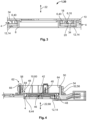
- Fig. 1
- a schematic sectional view of a mounting arrangement according to a possible embodiment, the component fixation member being a spring latch;
- Fig. 2
- a schematic sectional view of a mounting arrangement according to another possible embodiment, the component fixation member having convex sections;
- Fig. 3
- a schematic sectional view of a mounting arrangement according to a further possible embodiment, one component fixation member being an O-ring;
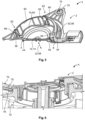
- Fig. 4
- a schematic sectional view of a mounting arrangement according to a another possible embodiment, comprising a sealing element and a holder;
- Fig. 5
- a schematic sectional view of a mounting arrangement according to yet another possible embodiment, further comprising mounting flanges;
- Fig. 6
- a schematic sectional view of a mounting arrangement according to a further possible embodiment, being assembled with a device.
- In the following, the structure and functionality of the mounting arrangement according to several embodiments is described with reference to
Fig. 1 to Fig. 6 . - As seen in
Fig. 1 , the mountingarrangement 1 comprises ahousing 2, areceptacle 4, and at least onecomponent fixation member 6. Thehousing 2 comprises ahousing base 8 and ahousing cover 10. Thehousing cover 10 is mounted onto thehousing base 8, such that they are fixedly attached to each other. Thereceptacle 4 is located between thehousing base 8 and thehousing cover 10 and is configured to accommodate an electronic component 12. In the embodiment shown inFig. 1 , thereceptacle 4 is substantially cuboid. The electronic component 12, which in this embodiment is a PCB 14, is received in thereceptacle 4, such that the PCB 14 is enclosed by thehousing base 8 and thehousing cover 10. - The
component fixation member 6 is elastically deformable and configured to be located in thereceptacle 4. In the embodiment ofFig. 1 , acomponent fixation member 6 is exemplary formed as a spring latch 16. The spring latch 16 may be formed monolithically with thehousing base 8 and may protrude towards thereceptacle 4. In the shown embodiment, the spring latch 16 comprises abase 18 and afree end 20. The base of the spring latch 16 may be monolithically formed with thehousing base 8, and thefree end 20 of the spring latch 16 contacts the PCB 14. The spring latch 16 is elastically deflectable along apressing direction 22, which in the shown embodiment extends along the normal direction 24 of thehousing base 8, the normal direction 26 of the PCB 14 and the normal direction 28 of thehousing cover 10. - The mounting
arrangement 1 shown inFig. 1 is in a mounted state 30. The PCB 14 is received in thereceptacle 4 between thehousing base 8 and thehousing cover 10 and the spring latch 16 is elastically deflected along a direction ofdeflection 32. In the shown embodiment, the direction ofdeflection 32 extends along thepressing direction 22. The elastically deflected spring latch 16 exerts a restoringforce 34, which acts opposite to the direction ofdeflection 32. As the spring latch 16, in particular thefree end 20 of the spring latch 16, abuts the PCB 14, the restoringforce 34 of the spring latch 16 is exerted on the PCB 14. As thehousing base 8 and thehousing cover 10 are fixedly connected to each other, relative movement between thehousing base 8 and thehousing cover 10 is prevented. In particular, movement is prevented along thepressing direction 22. Thus, thehousing cover 10 cannot escape the restoringforce 34 of the spring latch 16, which is why the PCB 14 is pushed against thehousing cover 10. The PCB 14 is clamped between thehousing base 8 and thehousing cover 10 and the PCB 14 is securely fixated in thereceptacle 4 of the mountingarrangement 1. - According to another embodiment, a
component fixation member 6 may comprise aconvex section 36. As shown inFig. 2 , thecomponent fixation member 6 may comprise twoconvex sections 36, which may be monolithically formed with thehousing cover 10. Eachconvex section 36 comprises an apex 38 that faces towards and/or protrudes into thereceptacle 4. Theconvex sections 36, in particular theapexes 38, are in contact with the PCB 14. The mountingarrangement 1 shown inFig. 2 is in the mounted state 30. The PCB 14 is accommodated in thereceptacle 4 between thehousing base 8 and thehousing cover 10 and theconvex sections 36 are elastically deformed along the direction ofdeflection 32 extending along thepressing direction 22. In analogy to the functionality of the mountingarrangement 1 according to the embodiment shown inFig. 1 , the elastically deformedconvex sections 36 exert the restoringforce 34, which counteracts the direction ofdeflection 32. As a consequence, the PCB 14 is pressed towards thehousing base 8 and thus clamped between thehousing cover 10 and thehousing base 8, such that the PCB 14 is securely fixated in thereceptacle 4. - As shown in the embodiment of
Fig. 3 , acomponent fixation member 6 may be an O-ring 40. The O-ring 40 may be located in thereceptacle 4, in particular between thehousing cover 10 and the PCB 14, such that the O-ring 40 abuts thehousing cover 10 and the PCB 14. In the mounted state 30, the O-ring 40 is elastically deformed or compressed between thehousing cover 10 and the PCB 14. The deformation or compression of the O-ring 40 causes the restoringforce 34 that tends to push thehousing cover 10 and the PCB 14 apart, in particular along thepressing direction 22. As the PCB 14 abuts thehousing base 8 and thehousing cover 10, and because thehousing base 8 and thehousing cover 10 are fixedly attached to each other, the PCB 14 is pressed against thehousing base 8. The PCB 14 is thereby fixated in thereceptacle 4, as the PCB 14 is clamped between thehousing base 8 and the elastically deflected O-ring 40. - In another embodiment, the mounting
arrangement 1 may comprise more than onecomponent fixation member 6. Thecomponent fixation members 6 may each be designed differently. As further shown inFig. 3 , the mountingarrangement 1 may comprise, in addition to the O-ring 40, anothercomponent fixation member 6 that may be designed as a spring latch 16. In the shown embodiment, the spring latch 16 protrudes from thehousing cover 10 and into thereceptacle 4. In particular, thebase 18 of the spring latch 16 may be monolithically formed with thehousing cover 10 and thefree end 20 of the spring latch 16 may abut the PCB 14. The functionality of the spring latch 16 is similar to the functionality of the spring latch 16 described before with reference toFig. 1 . In the mounted state 30, the spring latch 16 pushes the PCB 14 against thehousing base 8. Bothcomponent fixation members 6 shown inFig. 3 , namely the spring latch 16 and the O-ring 40, thus push the PCB 14 against thehousing base 8, whereby the PCB 14 is fixated in thereceptacle 4 of the mountingarrangement 1. - According to another embodiment, the
housing base 8 and/or thehousing cover 10 may comprise at least oneengagement protrusion 42. In the embodiment shown inFig. 4 , thehousing base 8 is provided with anengagement protrusion 42. Theengagement protrusion 42 may protrude perpendicular to aflat portion 44 of thehousing base 8 and into thereceptacle 4. In particular, theengagement protrusion 42 of thehousing base 8 may penetrate a through-hole 46 in the PCB 14, the through-hole 46 being complementary to theengagement protrusion 42 of thehousing base 8. When theengagement protrusion 42 of thehousing base 8 and the through-hole 46 of the PCB 14 are engaged, relative movement perpendicular to theengagement protrusion 42 between thehousing base 8 and the PCB 14 may be prevented. - As further shown in
Fig. 4 , in one embodiment, thehousing base 8 and thehousing cover 10 may comprisewelding sections 48, via which thehousing base 8 and thehousing cover 10 may be connected, e.g. by laser welding. At least one of thewelding sections 48 may - according to yet another embodiment - be located at theengagement protrusion 42 of thehousing base 8 or thehousing cover 10. In the embodiment shown inFig. 4 , twowelding sections 48 are located at theengagement protrusion 42 of thehousing base 8. - As best seen in
Figs. 4 and5 , thehousing base 8 may further comprise acollar 50 and a sealing element 52. In the shown embodiment, thecollar 50 is substantially cylindrical and perpendicularly protrudes from theflat portion 44 of thehousing base 8. Thecollar 50 may surround thereceptacle 4 that may be formed between theflat portion 44 of thehousing base 8 and thehousing cover 10. The sealing element 52 may circumferentially extend around anouter side 54 of thecollar 50, theouter side 54 of thecollar 50 facing away from thereceptacle 4 and the PCB 14 received in thereceptacle 4. InFigs. 4 and5 , the sealing element 52 is provided as a sealing ring 56 concentrically surrounding thecollar 50. - As shown in
Figs. 4 and5 , thehousing cover 10 may further comprise at least oneholder 58. In the shown embodiment, theholders 58 perpendicularly protrude from a substantially flat portion 60 of thehousing cover 10 and theholders 58 are monolithically formed with thehousing cover 10. Eachholder 58 may comprise aU-shaped section 62 away from the flat portion 60 of thehousing cover 10. When thehousing cover 10 is inserted into thecollar 50 of thehousing base 8, theholders 58 extend along aninner side 64 of thecollar 50 and theU-shaped sections 62 surpass thecollar 50 perpendicular to thepressing direction 22. In particular, theU-shaped sections 62 of theholders 58 may extend from theinner side 64 of thecollar 50 to theouter side 54 of thecollar 50. Aleg 66 of theU-shaped sections 62 of theholders 58 may be located on theouter side 54 of thecollar 50, being positioned next to the sealing element 52. Thereby, the sealing element 52 may be prevented from moving along a longitudinal axis 68 of thecollar 50 and/or along thepressing direction 22, such that the sealing element 52 may be securely retained to thehousing base 8. - As best seen in
Figs. 5 and 6 , thehousing 2 of the mountingarrangement 1 may comprise mountingflanges 70, through which the mountingarrangement 1 may be connected to anotherdevice 72. Such adevice 72 may, for example, correspond to another housing or housing arrangement. In the embodiment shown inFigs. 5 and 6 , the mountingflanges 70 each are provided with a through-hole 74 adapted for engaging acomplementary projection 76 of thedevice 72. In another embodiment, at least one through-hole 74 of the mountingflanges 70 may be threaded. -
- 1
- mounting arrangement
- 2
- housing
- 4
- receptacle
- 6
- component fixation member
- 8
- housing base
- 10
- housing cover
- 12
- electronic component
- 14
- PCB
- 16
- spring latch
- 18
- base
- 20
- free end
- 22
- pressing direction
- 24
- normal direction of the housing base
- 26
- normal direction of the PCB
- 28
- normal direction of the housing cover
- 30
- mounted state
- 32
- direction of deflection
- 34
- restoring force
- 36
- convex section
- 38
- apex
- 40
- O-ring
- 42
- engagement protrusion
- 44
- flat portion of the housing base
- 46
- through-hole of the PCB
- 48
- welding section
- 50
- collar
- 52
- sealing element
- 54
- outer side of the collar
- 56
- sealing ring
- 58
- holder
- 60
- flat portion of the housing cover
- 62
- U-shaped section
- 64
- inner side of the collar
- 66
- leg of the U-shaped section
- 68
- longitudinal axis of the collar
- 70
- mounting flange
- 72
- device
- 74
- through-hole
- 76
- projection
Claims (14)
- A mounting arrangement (1) for holding an electronic component, comprisinga housing (2) having a housing base (8) and a housing cover (10) configured to be mounted onto the housing base (8),a receptacle (4) for accommodating an electronic component (12), such as a PCB (14), between the housing base (8) and the mounted housing cover (8), andat least one component fixation member (6) which is elastically deformable and configured to be located in the receptacle (4) for fixating the electronic component (12) in the receptacle (4).
- A mounting arrangement (1) according to claim 1, wherein
a component fixation member (6) is monolithically formed with the housing base (8). - A mounting arrangement (1) according to claims 1 or 2, wherein
a component fixation member (6) is monolithically formed with the housing cover (10). - A mounting arrangement (1) according to any one of claims 1 to 3, wherein
a component fixation member (6) is formed as a spring latch (16) protruding towards the receptacle (4) at least partially. - A mounting arrangement (1) according to any one of claims 1 to 4, wherein
a component fixation member (6) comprises a convex section (36) protruding towards the receptacle (4). - A mounting arrangement (1) according to claim 1, wherein
a component fixation member (6) is an O-Ring (40). - A mounting arrangement (1) according to any one of claims 1 to 6, wherein
the mounting arrangement (1) comprises at least one component fixation member (6) of the group of component fixation members (6) comprising:- a spring latch (16);- a spring latch (16) being monolithically formed with the housing base (8);- a spring latch (16) being monolithically formed with the housing cover (10);- a component fixation member (6) comprising a convex section (36);- a component fixation member (6) comprising a convex section (36), the component fixation member (6) being monolithically formed with the housing base (8);- a component fixation member (6) comprising a convex section (36), the component fixation member (6) being monolithically formed with the housing cover (10);- an O-ring (40). - A mounting arrangement (1) according to any one of claims 1 to 7, wherein
the housing base (8) and/or the housing cover (10) comprises at least one engagement protrusion (42) at least partially penetrating the receptacle (4). - A mounting arrangement (1) according to any one of claims 1 to 8, wherein
the housing base (8) and the housing cover (10) are joined by laser welding in at least one welding section (48). - A mounting arrangement (1) according to claim 9, wherein
a welding section (48) is located at an engagement protrusion (42). - A mounting arrangement (1) according to any one of claims 1 to 10, whereinthe housing base (8) comprises a collar (50) surrounding the receptacle (4), anda sealing element (52) is provided, the sealing element (52) extending around an outer side (54) of the collar (50), the outer side (54) facing away from the receptacle (4).
- A mounting arrangement (1) according to claim 11, whereinthe housing cover (10) comprises at least one holder (58) adapted for holding the sealing element (52) in position, whereinthe at least one holder (58) surpasses the collar perpendicular to the pressing direction (22).
- A mounting arrangement (1) according to claim 12, wherein
a holder (58) is monolithically formed with the housing cover (10). - A mounting arrangement (1) according to any one of claims 1 to 13, wherein
the housing (2) comprises at least one mounting flange (70) via which the mounting arrangement (1) is connectable to another device (72).
Priority Applications (3)
| Application Number | Priority Date | Filing Date | Title |
|---|---|---|---|
| EP23197764.6A EP4525570A1 (en) | 2023-09-15 | 2023-09-15 | Mounting arrangement for an electronic component |
| CN202411274179.XA CN119653650A (en) | 2023-09-15 | 2024-09-12 | Mounting device for electronic components |
| US18/884,309 US20250098078A1 (en) | 2023-09-15 | 2024-09-13 | Mounting arrangement for an electronic component |
Applications Claiming Priority (1)
| Application Number | Priority Date | Filing Date | Title |
|---|---|---|---|
| EP23197764.6A EP4525570A1 (en) | 2023-09-15 | 2023-09-15 | Mounting arrangement for an electronic component |
Publications (1)
| Publication Number | Publication Date |
|---|---|
| EP4525570A1 true EP4525570A1 (en) | 2025-03-19 |
Family
ID=88197345
Family Applications (1)
| Application Number | Title | Priority Date | Filing Date |
|---|---|---|---|
| EP23197764.6A Pending EP4525570A1 (en) | 2023-09-15 | 2023-09-15 | Mounting arrangement for an electronic component |
Country Status (3)
| Country | Link |
|---|---|
| US (1) | US20250098078A1 (en) |
| EP (1) | EP4525570A1 (en) |
| CN (1) | CN119653650A (en) |
Citations (3)
| Publication number | Priority date | Publication date | Assignee | Title |
|---|---|---|---|---|
| DE10159063A1 (en) * | 2001-12-01 | 2003-08-14 | Hella Kg Hueck & Co | Circuit board and sensor enclosure, has fixing pins which are elastic and engage in recesses in circuit board such that a biasing force is exerted parallel to circuit board |
| CN207070539U (en) * | 2017-06-22 | 2018-03-02 | 合肥惠科金扬科技有限公司 | Circuit board mounting structure and display |
| CN219328892U (en) * | 2022-12-20 | 2023-07-11 | 国网黑龙江省电力有限公司供电服务中心 | Electric energy remote data acquisition device with wireless data interface |
Family Cites Families (28)
| Publication number | Priority date | Publication date | Assignee | Title |
|---|---|---|---|---|
| FR2191303B1 (en) * | 1972-06-30 | 1980-05-09 | Fischer Artur | |
| US5091606A (en) * | 1988-04-25 | 1992-02-25 | Peter J. Balsells | Gasket for sealing electromagnetic waves filled with a conductive material |
| US5280412A (en) * | 1993-04-06 | 1994-01-18 | Pacific Monolithics | Thermal/electrical feedthrough seal |
| US5402313A (en) * | 1993-05-21 | 1995-03-28 | Cummins Engine Company, Inc. | Electronic component heat sink attachment using a canted coil spring |
| US5745347A (en) * | 1996-10-11 | 1998-04-28 | Osram Sylvania Inc. | Adapter for connecting airbag accelerometer to a printed circuit board and assembly thereof |
| US6027693A (en) * | 1997-04-25 | 2000-02-22 | Brk Brands, Inc. | Sealed replaceable sensor |
| DE19722602C2 (en) * | 1997-05-30 | 2001-03-29 | Lenze Gmbh & Co Kg Aerzen | Heat-dissipating housing for holding electrical or electronic components |
| JP2001024301A (en) * | 1999-07-07 | 2001-01-26 | Fujitsu Ltd | Wiring board and conductive elastic member |
| DE10126189C2 (en) * | 2001-05-30 | 2003-12-18 | Bosch Gmbh Robert | Housing for an electrical device, in particular a switching or control device in a motor vehicle |
| US6838619B1 (en) * | 2003-12-30 | 2005-01-04 | Symbol Technologies, Inc. | Tamper resistance apparatus for an electrical device and an electrical device including the apparatus |
| DE102005044867B4 (en) * | 2005-09-20 | 2021-08-19 | Vitesco Technologies GmbH | Combined fastening and contacting system for electrical components on printed circuit boards arranged one above the other |
| US20080053700A1 (en) * | 2006-09-06 | 2008-03-06 | O'connor Kurt F | Sealed electronic component |
| DE102007001407B4 (en) * | 2007-01-09 | 2016-02-25 | Continental Automotive Gmbh | Mounting arrangement for fixing superposed printed circuit boards in a housing |
| JP4910996B2 (en) * | 2007-11-13 | 2012-04-04 | 株式会社デンソー | Electronic control device having heat dissipation structure |
| TWM361778U (en) * | 2009-01-13 | 2009-07-21 | Hon Hai Prec Ind Co Ltd | Electrical connector and assembly thereof |
| JP2010287796A (en) * | 2009-06-12 | 2010-12-24 | Sony Corp | Electronics |
| DE102010002765A1 (en) * | 2010-03-11 | 2011-09-15 | Robert Bosch Gmbh | Housing base of a multi-part housing and method for mounting a housing |
| TW201239938A (en) * | 2010-11-24 | 2012-10-01 | Panasonic Corp | Load control switch and load control switch system |
| TWI422107B (en) * | 2011-09-06 | 2014-01-01 | Inventec Corp | Cover plate structure |
| US9368917B2 (en) * | 2011-12-23 | 2016-06-14 | Commscope Technologies Llc | Telecommunications cabling system, and electrical connection module and shielding interface therefor |
| US9332680B2 (en) * | 2013-03-15 | 2016-05-03 | Autoliv Asp, Inc. | Electrical gasket and electronic module having electrical gasket |
| US8976536B2 (en) * | 2013-04-10 | 2015-03-10 | Lenovo Enterprise Solutions (Singapore) Pte. Ltd. | Latching cam handle assembly for securing mated circuit boards |
| US9698582B2 (en) * | 2014-08-29 | 2017-07-04 | New York Air Brakes, LLC | Quick connection identification module junction box |
| US10826208B1 (en) * | 2017-01-30 | 2020-11-03 | Superior Sensor Technology | Sensor with integrated electrical contacts |
| DE202018106719U1 (en) * | 2018-11-26 | 2020-02-27 | Weidmüller Interface GmbH & Co. KG | Housing for receiving at least one electromechanical, electrical and / or electronic component |
| US11277927B2 (en) * | 2019-11-05 | 2022-03-15 | Lear Corporation | System and method for mounting an electronics arrangement |
| US11374366B2 (en) * | 2020-06-19 | 2022-06-28 | Lear Corporation | System and method for providing an electrical ground connection for a circuit assembly |
| DE102023100219A1 (en) * | 2022-01-06 | 2023-07-06 | Te Connectivity Solutions Gmbh | Electrical connector system |
-
2023
- 2023-09-15 EP EP23197764.6A patent/EP4525570A1/en active Pending
-
2024
- 2024-09-12 CN CN202411274179.XA patent/CN119653650A/en active Pending
- 2024-09-13 US US18/884,309 patent/US20250098078A1/en active Pending
Patent Citations (3)
| Publication number | Priority date | Publication date | Assignee | Title |
|---|---|---|---|---|
| DE10159063A1 (en) * | 2001-12-01 | 2003-08-14 | Hella Kg Hueck & Co | Circuit board and sensor enclosure, has fixing pins which are elastic and engage in recesses in circuit board such that a biasing force is exerted parallel to circuit board |
| CN207070539U (en) * | 2017-06-22 | 2018-03-02 | 合肥惠科金扬科技有限公司 | Circuit board mounting structure and display |
| CN219328892U (en) * | 2022-12-20 | 2023-07-11 | 国网黑龙江省电力有限公司供电服务中心 | Electric energy remote data acquisition device with wireless data interface |
Also Published As
| Publication number | Publication date |
|---|---|
| CN119653650A (en) | 2025-03-18 |
| US20250098078A1 (en) | 2025-03-20 |
Similar Documents
| Publication | Publication Date | Title |
|---|---|---|
| US11258189B2 (en) | Connector and connecting method | |
| CN101567509B (en) | Connector | |
| US20140170886A1 (en) | Electrical connector assembled component | |
| EP2171805B1 (en) | Right angle type spring connector | |
| GB2342237A (en) | Jack | |
| KR20100007906A (en) | Coaxial connector | |
| US6971917B2 (en) | Socket for an electrically operated device | |
| US11588257B2 (en) | Terminal and connector | |
| US9312623B2 (en) | Connector for electronic device | |
| KR910003912Y1 (en) | Connectro socket with slide switch | |
| US9236199B2 (en) | Switch | |
| EP3675298B1 (en) | Electrical connection box | |
| CN114616723A (en) | connector device | |
| US20250098078A1 (en) | Mounting arrangement for an electronic component | |
| US20260092697A1 (en) | Appliance Light | |
| JP7006829B1 (en) | connector | |
| CN111226149A (en) | Optical connector, optical module and jig member | |
| EP3624275A1 (en) | Connection terminal | |
| WO2006025510A1 (en) | Spring connector | |
| JP3049383B2 (en) | Snap ring for connector | |
| EP1374630B1 (en) | Electroacoustic transducer having spring contacts | |
| JP6095180B1 (en) | connector | |
| CN111316391B (en) | Mounting position adjusting member and switch device | |
| US9812805B2 (en) | Abutting type connector | |
| CN111755922B (en) | Connector device and substrate mounting method |
Legal Events
| Date | Code | Title | Description |
|---|---|---|---|
| PUAI | Public reference made under article 153(3) epc to a published international application that has entered the european phase |
Free format text: ORIGINAL CODE: 0009012 |
|
| STAA | Information on the status of an ep patent application or granted ep patent |
Free format text: STATUS: THE APPLICATION HAS BEEN PUBLISHED |
|
| AK | Designated contracting states |
Kind code of ref document: A1 Designated state(s): AL AT BE BG CH CY CZ DE DK EE ES FI FR GB GR HR HU IE IS IT LI LT LU LV MC ME MK MT NL NO PL PT RO RS SE SI SK SM TR |
|
| STAA | Information on the status of an ep patent application or granted ep patent |
Free format text: STATUS: REQUEST FOR EXAMINATION WAS MADE |
|
| 17P | Request for examination filed |
Effective date: 20250917 |