EP4525550A1 - Benutzergerätebetriebsverfahren im zusammenhang mit sidelink-drx-konfiguration für mehrpfadrelaisbetrieb in einem drahtloskommunikationssystem - Google Patents
Benutzergerätebetriebsverfahren im zusammenhang mit sidelink-drx-konfiguration für mehrpfadrelaisbetrieb in einem drahtloskommunikationssystem Download PDFInfo
- Publication number
- EP4525550A1 EP4525550A1 EP23803864.0A EP23803864A EP4525550A1 EP 4525550 A1 EP4525550 A1 EP 4525550A1 EP 23803864 A EP23803864 A EP 23803864A EP 4525550 A1 EP4525550 A1 EP 4525550A1
- Authority
- EP
- European Patent Office
- Prior art keywords
- remote
- drx
- relay
- base station
- information
- Prior art date
- Legal status (The legal status is an assumption and is not a legal conclusion. Google has not performed a legal analysis and makes no representation as to the accuracy of the status listed.)
- Pending
Links
Images


Classifications
-
- H—ELECTRICITY
- H04—ELECTRIC COMMUNICATION TECHNIQUE
- H04W—WIRELESS COMMUNICATION NETWORKS
- H04W40/00—Communication routing or communication path finding
- H04W40/02—Communication route or path selection, e.g. power-based or shortest path routing
- H04W40/22—Communication route or path selection, e.g. power-based or shortest path routing using selective relaying for reaching a BTS [Base Transceiver Station] or an access point
-
- H—ELECTRICITY
- H04—ELECTRIC COMMUNICATION TECHNIQUE
- H04W—WIRELESS COMMUNICATION NETWORKS
- H04W76/00—Connection management
- H04W76/20—Manipulation of established connections
- H04W76/28—Discontinuous transmission [DTX]; Discontinuous reception [DRX]
-
- H—ELECTRICITY
- H04—ELECTRIC COMMUNICATION TECHNIQUE
- H04W—WIRELESS COMMUNICATION NETWORKS
- H04W76/00—Connection management
- H04W76/10—Connection setup
- H04W76/14—Direct-mode setup
-
- H—ELECTRICITY
- H04—ELECTRIC COMMUNICATION TECHNIQUE
- H04W—WIRELESS COMMUNICATION NETWORKS
- H04W72/00—Local resource management
- H04W72/20—Control channels or signalling for resource management
- H04W72/21—Control channels or signalling for resource management in the uplink direction of a wireless link, i.e. towards the network
-
- H—ELECTRICITY
- H04—ELECTRIC COMMUNICATION TECHNIQUE
- H04W—WIRELESS COMMUNICATION NETWORKS
- H04W72/00—Local resource management
- H04W72/40—Resource management for direct mode communication, e.g. D2D or sidelink
-
- H—ELECTRICITY
- H04—ELECTRIC COMMUNICATION TECHNIQUE
- H04W—WIRELESS COMMUNICATION NETWORKS
- H04W76/00—Connection management
- H04W76/20—Manipulation of established connections
- H04W76/27—Transitions between radio resource control [RRC] states
-
- H—ELECTRICITY
- H04—ELECTRIC COMMUNICATION TECHNIQUE
- H04W—WIRELESS COMMUNICATION NETWORKS
- H04W8/00—Network data management
- H04W8/005—Discovery of network devices, e.g. terminals
-
- H—ELECTRICITY
- H04—ELECTRIC COMMUNICATION TECHNIQUE
- H04W—WIRELESS COMMUNICATION NETWORKS
- H04W88/00—Devices specially adapted for wireless communication networks, e.g. terminals, base stations or access point devices
- H04W88/02—Terminal devices
- H04W88/04—Terminal devices adapted for relaying to or from another terminal or user
-
- H—ELECTRICITY
- H04—ELECTRIC COMMUNICATION TECHNIQUE
- H04W—WIRELESS COMMUNICATION NETWORKS
- H04W92/00—Interfaces specially adapted for wireless communication networks
- H04W92/16—Interfaces between hierarchically similar devices
- H04W92/18—Interfaces between hierarchically similar devices between terminal devices
Definitions
- the following description relates to a wireless communication system, and more specifically, to a method and apparatus for operating a remote UE or a relay UE related to a method of configuring a Sidelink (SL) Discontinuous Reception (DRX) configuration in a multi-path.
- SL Sidelink
- DRX Discontinuous Reception
- a wireless communication system is a multiple access system capable of supporting communication with multiple users by sharing available system resources (bandwidth, transmission power, etc.).
- Examples of the multiple access system include a code division multiple access (CDMA) system, a frequency division multiple access (FDMA) system, a time division multiple access (TDMA) system, an orthogonal frequency division multiple access (OFDMA) system, and a single carrier frequency division multiple access (SC-FDMA) system, and a multi carrier frequency division multiple access (MC-FDMA) system.
- CDMA code division multiple access
- FDMA frequency division multiple access
- TDMA time division multiple access
- OFDMA orthogonal frequency division multiple access
- SC-FDMA single carrier frequency division multiple access
- MC-FDMA multi carrier frequency division multiple access
- a wireless communication system uses various radio access technologies (RATs) such as long term evolution (LTE), LTE-advanced (LTE-A), and wireless fidelity (WiFi).
- RATs radio access technologies
- LTE long term evolution
- LTE-A LTE-advanced
- WiFi wireless fidelity
- 5th generation (5G) is such a wireless communication system.
- Three key requirement areas of 5G include (1) enhanced mobile broadband (eMBB), (2) massive machine type communication (mMTC), and (3) ultra-reliable and low latency communications (URLLC).
- eMBB enhanced mobile broadband
- mMTC massive machine type communication
- URLLC ultra-reliable and low latency communications
- KPI key performance indicator
- 5G supports such diverse use cases in a flexible and reliable way.
- eMBB goes far beyond basic mobile Internet access and covers rich interactive work, media and entertainment applications in the cloud or augmented reality (AR).
- Data is one of the key drivers for 5G and in the 5G era, we may for the first time see no dedicated voice service.
- voice is expected to be handled as an application program, simply using data connectivity provided by a communication system.
- the main drivers for an increased traffic volume are the increase in the size of content and the number of applications requiring high data rates.
- Streaming services (audio and video), interactive video, and mobile Internet connectivity will continue to be used more broadly as more devices connect to the Internet. Many of these applications require always-on connectivity to push real time information and notifications to users.
- Cloud storage and applications are rapidly increasing for mobile communication platforms. This is applicable for both work and entertainment.
- Cloud storage is one particular use case driving the growth of uplink data rates.
- 5G will also be used for remote work in the cloud which, when done with tactile interfaces, requires much lower end-to-end latencies in order to maintain a good user experience.
- Entertainment for example, cloud gaming and video streaming, is another key driver for the increasing need for mobile broadband capacity. Entertainment will be very essential on smart phones and tablets everywhere, including high mobility environments such as trains, cars and airplanes.
- AR augmented reality
- 5G is one of areas that play key roles in enabling smart city, asset tracking, smart utility, agriculture, and security infrastructure.
- URLLC includes services which will transform industries with ultra-reliable/available, low latency links such as remote control of critical infrastructure and self-driving vehicles.
- the level of reliability and latency are vital to smart-grid control, industrial automation, robotics, drone control and coordination, and so on.
- 5G may complement fiber-to-the home (FTTH) and cable-based broadband (or data-over-cable service interface specifications (DOCSIS)) as a means of providing streams at data rates of hundreds of megabits per second to giga bits per second.
- FTTH fiber-to-the home
- DOCSIS data-over-cable service interface specifications
- VR and AR applications mostly include immersive sport games.
- a special network configuration may be required for a specific application program.
- game companies may have to integrate a core server with an edge network server of a network operator in order to minimize latency.
- the automotive sector is expected to be a very important new driver for 5G, with many use cases for mobile communications for vehicles. For example, entertainment for passengers requires simultaneous high capacity and high mobility mobile broadband, because future users will expect to continue their good quality connection independent of their location and speed.
- Other use cases for the automotive sector are AR dashboards. These display overlay information on top of what a driver is seeing through the front window, identifying objects in the dark and telling the driver about the distances and movements of the objects.
- wireless modules will enable communication between vehicles themselves, information exchange between vehicles and supporting infrastructure and between vehicles and other connected devices (e.g., those carried by pedestrians).
- Safety systems may guide drivers on alternative courses of action to allow them to drive more safely and lower the risks of accidents.
- the next stage will be remote-controlled or self-driving vehicles.
- Smart cities and smart homes often referred to as smart society, will be embedded with dense wireless sensor networks.
- Distributed networks of intelligent sensors will identify conditions for cost- and energy-efficient maintenance of the city or home.
- a similar setup can be done for each home, where temperature sensors, window and heating controllers, burglar alarms, and home appliances are all connected wirelessly.
- Many of these sensors are typically characterized by low data rate, low power, and low cost, but for example, real time high definition (HD) video may be required in some types of devices for surveillance.
- HD high definition
- a smart grid interconnects such sensors, using digital information and communications technology to gather and act on information. This information may include information about the behaviors of suppliers and consumers, allowing the smart grid to improve the efficiency, reliability, economics and sustainability of the production and distribution of fuels such as electricity in an automated fashion.
- a smart grid may be seen as another sensor network with low delays.
- the health sector has many applications that may benefit from mobile communications.
- Communications systems enable telemedicine, which provides clinical health care at a distance. It helps eliminate distance barriers and may improve access to medical services that would often not be consistently available in distant rural communities. It is also used to save lives in critical care and emergency situations.
- Wireless sensor networks based on mobile communication may provide remote monitoring and sensors for parameters such as heart rate and blood pressure.
- Wireless and mobile communications are becoming increasingly important for industrial applications. Wires are expensive to install and maintain, and the possibility of replacing cables with reconfigurable wireless links is a plausible opportunity for many industries. However, achieving this requires that the wireless connection works with a similar delay, reliability and capacity as cables and that its management is simplified. Low delays and very low error probabilities are new requirements that need to be addressed with 5G
- logistics and freight tracking are important use cases for mobile communications that enable the tracking of inventory and packages wherever they are by using location-based information systems.
- the logistics and freight tracking use cases typically require lower data rates but need wide coverage and reliable location information.
- a wireless communication system is a multiple access system that supports communication of multiple users by sharing available system resources (a bandwidth, transmission power, etc.).
- multiple access systems include a CDMA system, an FDMA system, a TDMA system, an OFDMA system, an SC-FDMA system, and an MC-FDMA system.
- SL refers to a communication scheme in which a direct link is established between user equipments (UEs) and the UEs directly exchange voice or data without intervention of a base station (BS).
- UEs user equipments
- BS base station
- SL is considered as a solution of relieving the BS of the constraint of rapidly growing data traffic.
- V2X Vehicle-to-everything
- V2X is a communication technology in which a vehicle exchanges information with another vehicle, a pedestrian, and infrastructure by wired/wireless communication.
- V2X may be categorized into four types: vehicle-to-vehicle (V2V), vehicle-to-infrastructure (V2I), vehicle-to-network (V2N), and vehicle-to-pedestrian (V2P).
- V2X communication may be provided via a PC5 interface and/or a Uu interface.
- next-generation RAT in which eMBB, MTC, and URLLC are considered is referred to as new RAT or NR.
- new RAT In NR, V2X communication may also be supported.
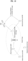
- FIG. 1 is a diagram illustrating V2X communication based on pre-NR RAT and V2X communication based on NR in comparison.
- V2X communication For V2X communication, a technique of providing safety service based on V2X messages such as basic safety message (BSM), cooperative awareness message (CAM), and decentralized environmental notification message (DENM) was mainly discussed in the pre-NR RAT.
- the V2X message may include location information, dynamic information, and attribute information.
- a UE may transmit a CAM of a periodic message type and/or a DENM of an event-triggered type to another UE.
- the CAM may include basic vehicle information including dynamic state information such as a direction and a speed, vehicle static data such as dimensions, an external lighting state, path details, and so on.
- the UE may broadcast the CAM which may have a latency less than 100 ms.
- the UE may generate the DENM and transmit the DENM to another UE.
- all vehicles within the transmission range of the UE may receive the CAM and/or the DENM.
- the DENM may have priority over the CAM.
- V2X scenarios are presented in NR.
- the V2X scenarios include vehicle platooning, advanced driving, extended sensors, and remote driving.
- vehicles may be dynamically grouped and travel together based on vehicle platooning.
- the vehicles of the group may receive periodic data from a leading vehicle.
- the vehicles of the group may widen or narrow their gaps based on the periodic data.
- a vehicle may be semi-automated or full-automated based on advanced driving.
- each vehicle may adjust a trajectory or maneuvering based on data obtained from a nearby vehicle and/or a nearby logical entity.
- each vehicle may also share a dividing intention with nearby vehicles.
- raw or processed data obtained through local sensor or live video data may be exchanged between vehicles, logical entities, terminals of pedestrians and/or V2X application servers. Accordingly, a vehicle may perceive an advanced environment relative to an environment perceivable by its sensor.
- a remote driver or a V2X application may operate or control a remote vehicle on behalf of a person incapable of driving or in a dangerous environment.
- cloud computing-based driving may be used in operating or controlling the remote vehicle.
- access to a cloud-based back-end service platform may also be used for remote driving.
- a scheme of specifying service requirements for various V2X scenarios including vehicle platooning, advanced driving, extended sensors, and remote driving is under discussion in NR-based V2X communication.
- One technical task of the present disclosure is to provide an SL DRX configuring method in multi-path, in which a remote UE and/or a relay UE directly reports an SL DRX configuration preferred by itself to a gNB so that the gNB directly may configure an SL DRX to use for SL communication with a counterpart UE.
- a method of operating a remote User Equipment (UE) in a wireless communication system including establishing a Radio Resource Control (RRC) connection with a relay UE by the remote UE and transmitting sidelink information including preferred DRX configuration information of the remote UE to a base station by the remote UE, wherein based on both the remote UE and the relay UE being RRC_CONNECTED with the base station, the remote UE receives an SL DRX configuration of the relay UE and an SL DRX configuration of the remote UE directly from the base station and applies the SL DRX configuration of the remote UE.
- RRC Radio Resource Control
- an apparatus for a remote UE in a wireless communication system including at least one processor and at least one computer memory operably connected to the at least one processor and storing instructions causing the at least one processor to perform operations when executed, the operations including establishing a Radio Resource Control (RRC) connection with a relay UE by the remote UE and transmitting sidelink information including preferred DRX configuration information of the remote UE to a base station by the remote UE, wherein based on both the remote UE and the relay UE being RRC_CONNECTED with the base station, the remote UE receives an SL DRX configuration of the relay UE and an SL DRX configuration of the remote UE directly from the base station and applies the SL DRX configuration of the remote UE.
- RRC Radio Resource Control
- the remote UE may directly transmit the preferred DRX configuration information to the base station.
- the remote UE may receive the SL DRX configuration from the base station through the relay UE.
- the remote UE may transmit the preferred DRX configuration information to the base station through the relay UE.
- Being unable to directly perform transmission and reception with the base station may include a case of the remote UE being out coverage or a case of the remote UE being RRC_CONNECTED_CONNECTED to a different base station other than the base station.
- the operations may be based on recognizing that the remote UE is capable of using a multi-path in which both a direct link to the base station and an indirect link to the base station through the relay UE are active.
- the remote UE may recognize that it is possible to use the multi-path based on the base station separately configuring a Uu bearer for the multi-path or an SL bearer for the multi-path.
- the remote UE may recognize that it is possible to use the multi-path.
- the remote UE may recognize that it is possible to use the multi-path.
- the remote UE may inform the relay UE that it is possible to use the multi-path.
- the sidelink information may be SidelinkUEInformation.
- the remote UE may operate in resource allocation mode 2.
- signal overhead for an SL DRX configuration reduced between a TX UE and an RX UE may be reduced, and a DRX configuration may be applied quickly compared to non-multipath cases
- A/B may mean “A and/or B”.
- A, B may mean “A and/or B”.
- A/B/C may mean “at least one of A, B and/or C”.
- A, B, C may mean “at least one of A, B and/or C”.
- CDMA code division multiple access
- FDMA frequency division multiple access
- TDMA time division multiple access
- OFDMA orthogonal frequency division multiple access
- SC-FDMA single carrier-frequency division multiple access
- CDMA may be implemented as a radio technology such as universal terrestrial radio access (UTRA) or CDMA2000.
- TDMA may be implemented as a radio technology such as global system for mobile communications (GSM)/general packet radio service (GPRS)/Enhanced Data Rates for GSM Evolution (EDGE).
- GSM global system for mobile communications
- GPRS general packet radio service
- EDGE Enhanced Data Rates for GSM Evolution
- OFDMA may be implemented as a radio technology such as IEEE 802.11 (Wi-Fi), IEEE 802.16 (WiMAX), IEEE 802.20, evolved-UTRA (E-UTRA), or the like.
- IEEE 802.16m is an evolution of IEEE 802.16e, offering backward compatibility with an IRRR 802.16e-based system.
- UTRA is a part of universal mobile telecommunications system (UMTS).
- 3rd generation partnership project (3GPP) long term evolution (LTE) is a part of evolved UMTS (E-UMTS) using evolved UTRA (E-UTRA).
- 3GPP LTE employs OFDMA for downlink (DL) and SC-FDMA for uplink (UL).
- LTE-advanced (LTE-A) is an evolution of 3GPP LTE.
- 5G new radio access technology is a new clean-state mobile communication system characterized by high performance, low latency, and high availability.
- 5G NR may use all available spectral resources including a low frequency band below 1 GHz, an intermediate frequency band between 1 GHz and 10 GHz, and a high frequency (millimeter) band of 24 GHz or above.
- FIG. 2 illustrates the structure of an LTE system according to an embodiment of the present disclosure. This may also be called an evolved UMTS terrestrial radio access network (E-UTRAN) or LTE/LTE-A system.
- E-UTRAN evolved UMTS terrestrial radio access network
- LTE/LTE-A system LTE/LTE-A system
- the E-UTRAN includes evolved Node Bs (eNBs) 20 which provide a control plane and a user plane to UEs 10.
- a UE 10 may be fixed or mobile, and may also be referred to as a mobile station (MS), user terminal (UT), subscriber station (SS), mobile terminal (MT), or wireless device.
- An eNB 20 is a fixed station communication with the UE 10 and may also be referred to as a base station (BS), a base transceiver system (BTS), or an access point.
- BS base station
- BTS base transceiver system
- eNBs 20 may be connected to each other via an X2 interface.
- An eNB 20 is connected to an evolved packet core (EPC) 39 via an S1 interface. More specifically, the eNB 20 is connected to a mobility management entity (MME) via an S1-MME interface and to a serving gateway (S-GW) via an S1-U interface.
- EPC evolved packet core
- MME mobility management entity
- S-GW serving gateway
- the radio protocol stack between a UE and a network may be divided into Layer 1 (L1), Layer 2 (L2) and Layer 3 (L3). These layers are defined in pairs between a UE and an Evolved UTRAN (E-UTRAN), for data transmission via the Uu interface.
- L1 Layer 1
- L2 Layer 2
- L3 Layer 3
- PHY physical
- RRC radio resource control
- FIG. 3(a) illustrates a user-plane radio protocol architecture according to an embodiment of the disclosure.
- FIG. 3(b) illustrates a control-plane radio protocol architecture according to an embodiment of the disclosure.
- a user plane is a protocol stack for user data transmission
- a control plane is a protocol stack for control signal transmission.
- the PHY layer provides an information transfer service to its higher layer on physical channels.
- the PHY layer is connected to the medium access control (MAC) layer through transport channels and data is transferred between the MAC layer and the PHY layer on the transport channels.
- the transport channels are divided according to features with which data is transmitted via a radio interface.
- the physical channels may be modulated in orthogonal frequency division multiplexing (OFDM) and use time and frequencies as radio resources.
- OFDM orthogonal frequency division multiplexing
- the MAC layer provides services to a higher layer, radio link control (RLC) on logical channels.
- RLC radio link control
- the MAC layer provides a function of mapping from a plurality of logical channels to a plurality of transport channels. Further, the MAC layer provides a logical channel multiplexing function by mapping a plurality of logical channels to a single transport channel.
- a MAC sublayer provides a data transmission service on the logical channels.
- the RLC layer performs concatenation, segmentation, and reassembly for RLC serving data units (SDUs).
- SDUs RLC serving data units
- the RLC layer provides three operation modes, transparent mode (TM), unacknowledged mode (UM), and acknowledged Mode (AM).
- TM transparent mode
- UM unacknowledged mode
- AM acknowledged Mode
- An AM RLC provides error correction through automatic repeat request (ARQ).
- the RRC layer is defined only in the control plane and controls logical channels, transport channels, and physical channels in relation to configuration, reconfiguration, and release of RBs.
- An RB refers to a logical path provided by L1 (the PHY layer) and L2 (the MAC layer, the RLC layer, and the packet data convergence protocol (PDCP) layer), for data transmission between the UE and the network.
- L1 the PHY layer
- L2 the MAC layer, the RLC layer, and the packet data convergence protocol (PDCP) layer
- the user-plane functions of the PDCP layer include user data transmission, header compression, and ciphering.
- the control-plane functions of the PDCP layer include control-plane data transmission and ciphering/integrity protection.
- RB establishment amounts to a process of defining radio protocol layers and channel features and configuring specific parameters and operation methods in order to provide a specific service.
- RBs may be classified into two types, signaling radio bearer (SRB) and data radio bearer (DRB).
- SRB is used as a path in which an RRC message is transmitted on the control plane
- DRB is used as a path in which user data is transmitted on the user plane.
- RRC_CONNECTED Once an RRC connection is established between the RRC layer of the UE and the RRC layer of the E-UTRAN, the UE is placed in RRC_CONNECTED state, and otherwise, the UE is placed in RRC_IDLE state.
- RRC_INACTIVE state is additionally defined.
- a UE in the RRC_INACTIVE state may maintain a connection to a core network, while releasing a connection from an eNB.
- DL transport channels carrying data from the network to the UE include a broadcast channel (BCH) on which system information is transmitted and a DL shared channel (DL SCH) on which user traffic or a control message is transmitted. Traffic or a control message of a DL multicast or broadcast service may be transmitted on the DL-SCH or a DL multicast channel (DL MCH).
- UL transport channels carrying data from the UE to the network include a random access channel (RACH) on which an initial control message is transmitted and an UL shared channel (UL SCH) on which user traffic or a control message is transmitted.
- RACH random access channel
- UL SCH UL shared channel
- the logical channels which are above and mapped to the transport channels include a broadcast control channel (BCCH), a paging control channel (PCCH), a common control channel (CCCH), a multicast control channel (MCCH), and a multicast traffic channel (MTCH).
- BCCH broadcast control channel
- PCCH paging control channel
- CCCH common control channel
- MCCH multicast control channel
- MTCH multicast traffic channel
- a physical channel includes a plurality of OFDM symbol in the time domain by a plurality of subcarriers in the frequency domain.
- One subframe includes a plurality of OFDM symbols in the time domain.
- An RB is a resource allocation unit defined by a plurality of OFDM symbols by a plurality of subcarriers.
- each subframe may use specific subcarriers of specific OFDM symbols (e.g., the first OFDM symbol) in a corresponding subframe for a physical DL control channel (PDCCH), that is, an L1/L2 control channel.
- a transmission time interval (TTI) is a unit time for subframe transmission.
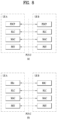
- FIG. 4 illustrates the structure of an NR system according to an embodiment of the present disclosure.
- a next generation radio access network may include a next generation Node B (gNB) and/or an eNB, which provides user-plane and control-plane protocol termination to a UE.
- the NG-RAN is shown as including only gNBs, by way of example.
- a gNB and an eNB are connected to each other via an Xn interface.
- the gNB and the eNB are connected to a 5G core network (5GC) via an NG interface.
- 5GC 5G core network
- the gNB and the eNB are connected to an access and mobility management function (AMF) via an NG-C interface and to a user plane function (UPF) via an NG-U interface.
- AMF access and mobility management function
- UPF user plane function
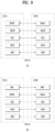
- FIG. 5 illustrates functional split between the NG-RAN and the 5GC according to an embodiment of the present disclosure.
- a gNB may provide functions including inter-cell radio resource management (RRM), radio admission control, measurement configuration and provision, and dynamic resource allocation.
- the AMF may provide functions such as non-access stratum (NAS) security and idle-state mobility processing.
- the UPF may provide functions including mobility anchoring and protocol data unit (PDU) processing.
- a session management function (SMF) may provide functions including UE Internet protocol (IP) address allocation and PDU session control.
- IP Internet protocol
- FIG. 6 illustrates a radio frame structure in NR, to which embodiment(s) of the present disclosure is applicable.
- a radio frame may be used for UL transmission and DL transmission in NR.
- a radio frame is 10ms in length, and may be defined by two 5-ms half-frames.
- An HF may include five 1-ms subframes.
- a subframe may be divided into one or more slots, and the number of slots in an SF may be determined according to a subcarrier spacing (SCS).
- SCS subcarrier spacing
- Each slot may include 12 or 14 OFDM(A) symbols according to a cyclic prefix (CP).
- CP cyclic prefix
- each slot may include 14 symbols, whereas in an extended CP (ECP) case, each slot may include 12 symbols.
- a symbol may be an OFDM symbol (or CP-OFDM symbol) or an SC-FDMA symbol (or DFT-s-OFDM symbol).
- Table 1 below lists the number of symbols per slot N slot symb , the number of slots per frame N frame,u slot , and the number of slots per subframe N subframe,u slot according to an SCS configuration ⁇ in the NCP case.
- different OFDM(A) numerologies e.g., SCSs, CP lengths, and so on
- SCSs subframe, slot, or TTI
- TU time unit
- various numerologies or SCSs may be supported to support various 5G services. For example, with an SCS of 15 kHz, a wide area in traditional cellular bands may be supported, while with an SCS of 30/60 kHz, a dense urban area, a lower latency, and a wide carrier bandwidth may be supported. With an SCS of 60 kHz or higher, a bandwidth larger than 24.25 GHz may be supported to overcome phase noise.
- An NR frequency band may be defined by two types of frequency ranges, FR1 and FR2.
- the numerals in each frequency range may be changed.
- the two types of frequency ranges may be given in [Table 3].
- FR1 may be a "sub 6 GHz range”
- FR2 may be an "above 6 GHz range” called millimeter wave (mmW).
- mmW millimeter wave
- [Table 3] Frequency Range designation Corresponding frequency range Subcarrier Spacing (SCS) FR1 450 MHz - 6000 MHz 15, 30, 60 kHz FR2 24250 MHz - 52600 MHz 60, 120, 240 kHz
- SCS Corresponding frequency range Subcarrier Spacing
- FR1 may range from 410 MHz to 7125 MHz as listed in [Table 4]. That is, FR1 may include a frequency band of 6 GHz (or 5850, 5900, and 5925 MHz) or above.
- the frequency band of 6 GHz (or 5850, 5900, and 5925 MHz) or above may include an unlicensed band.
- the unlicensed band may be used for various purposes, for example, vehicle communication (e.g., autonomous driving).
- FIG. 7 illustrates a slot structure in an NR frame according to an embodiment of the present disclosure.
- a slot includes a plurality of symbols in the time domain.
- one slot may include 14 symbols in an NCP case and 12 symbols in an ECP case.
- one slot may include 7 symbols in an NCP case and 6 symbols in an ECP case.
- a carrier includes a plurality of subcarriers in the frequency domain.
- An RB may be defined by a plurality of (e.g., 12) consecutive subcarriers in the frequency domain.
- a bandwidth part (BWP) may be defined by a plurality of consecutive (physical) RBs ((P)RBs) in the frequency domain and correspond to one numerology (e.g., SCS, CP length, or the like).
- a carrier may include up to N (e.g., 5) BWPs. Data communication may be conducted in an activated BWP.
- Each element may be referred to as a resource element (RE) in a resource grid, to which one complex symbol may be mapped.
- RE resource element
- a radio interface between UEs or a radio interface between a UE and a network may include L1, L2, and L3.
- L1 may refer to the PHY layer.
- L2 may refer to at least one of the MAC layer, the RLC layer, the PDCH layer, or the SDAP layer.
- L3 may refer to the RRC layer.
- FIG. 8 illustrates a radio protocol architecture for SL communication according to an embodiment of the present disclosure. Specifically, FIG. 8(a) illustrates a user-plane protocol stack in LTE, and FIG. 8(b) illustrates a control-plane protocol stack in LTE.
- FIG. 9 illustrates a radio protocol architecture for SL communication according to an embodiment of the present disclosure. Specifically, FIG. 9(a) illustrates a user-plane protocol stack in NR, and FIG. 9(b) illustrates a control-plane protocol stack in NR.
- FIG. 10 illustrates a synchronization source or synchronization reference of V2X according to an embodiment of the present disclosure.
- a UE may be directly synchronized with global navigation satellite systems (GNSS).
- GNSS global navigation satellite systems
- the UE may be indirectly synchronized with the GNSS through another UE (within or out of network coverage).
- the UE may calculate a direct frame number (DFN) and a subframe number based on a coordinated universal time (UTC) and a configured (or preconfigured) DFN offset.
- DFN direct frame number
- UTC coordinated universal time
- a UE may be directly synchronized with a BS or may be synchronized with another UE that is synchronized in time/frequency with the BS.
- the BS may be an eNB or a gNB.
- the UE may receive synchronization information provided by the BS and may be directly synchronized with the BS.
- the UE may provide the synchronization information to another adjacent UE.
- the UE may follow a cell associated with a corresponding frequency (when the UE is in cell coverage in frequency) or a primary cell or a serving cell (when the UE is out of cell coverage in frequency), for synchronization and DL measurement.
- the BS may provide a synchronization configuration for a carrier used for V2X/SL communication.
- the UE may conform to the synchronization configuration received from the BS. If the UE fails to detect any cell in the carrier used for V2X/SL communication and fails to receive the synchronization configuration from the serving cell, the UE may conform to a preset synchronization configuration.
- the UE may be synchronized with another UE that has failed to directly or indirectly acquire the synchronization information from the BS or the GNSS.
- a synchronization source and a preference may be preconfigured for the UE.
- the synchronization source and the preference may be configured through a control message provided by the BS.
- SL synchronization sources may be associated with synchronization priority levels.
- a relationship between synchronization sources and synchronization priorities may be defined as shown in Table 5 or 6.
- Table 5 or 6 is merely an example, and the relationship between synchronization sources and synchronization priorities may be defined in various ways.
- P0 may mean the highest priority
- P6 may mean the lowest priority
- the BS may include at least one of a gNB or an eNB.
- Whether to use GNSS-based synchronization or eNB/gNB-based synchronization may be (pre)configured.
- the UE may derive a transmission timing thereof from an available synchronization reference having the highest priority.
- SLSS sidelink synchronization signal
- the SLSS may include a primary sidelink synchronization signal (PSSS) and a secondary sidelink synchronization signal (SSSS).
- PSSS primary sidelink synchronization signal
- SSSS secondary sidelink synchronization signal
- the PSSS may be referred to as a sidelink primary synchronization signal (S-PSS)
- S-SSS sidelink secondary synchronization signal
- S-SSS sidelink secondary synchronization signal
- length-127 M-sequences may be used for the S-PSS
- length-127 gold sequences may be used for the S-SSS.
- the UE may use the S-PSS to detect an initial signal and obtain synchronization.
- the UE may use the S-PSS and the S-SSS to obtain detailed synchronization and detect a synchronization signal ID.
- a physical sidelink broadcast channel may be a (broadcast) channel for transmitting default (system) information that the UE needs to know first before transmitting and receiving SL signals.
- the default information may include information related to an SLSS, a duplex mode (DM), a time division duplex (TDD) UL/DL configuration, information related to a resource pool, an application type related to the SLSS, a subframe offset, broadcast information, etc.
- the payload size of the PSBCH may be 56 bits including a CRC of 24 bits.
- the S-PSS, S-SSS, and PSBCH may be included in a block format (e.g., SL synchronization signal (SS)/PSBCH block) supporting periodical transmission (hereinafter, the SL SS/PSBCH block is referred to as a sidelink synchronization signal block (S-SSB)).
- the S-SSB may have the same numerology (i.e., SCS and CP length) as that of a physical sidelink control channel (PSCCH)/physical sidelink shared channel (PSSCH) on a carrier, and the transmission bandwidth may exist within a configured (or preconfigured) SL BWP.
- the S-SSB may have a bandwidth of 11 RBs.
- the PSBCH may span 11 RBs.
- the frequency position of the S-SSB may be configured (or preconfigured). Therefore, the UE does not need to perform hypothesis detection on frequency to discover the S-SSB on the carrier.
- the NR SL system may support a plurality of numerologies with different SCSs and/or different CP lengths.
- the transmitting UE may transmit one or more S-SSBs to a receiving UE within one S-SSB transmission period based on the SCS.
- the number of S-SSBs that the transmitting UE transmits to the receiving UE within one S-SSB transmission period may be pre-configured or configured for the transmitting UE.
- the S-SSB transmission period may be 160 ms.
- an S-SSB transmission period of 160 ms may be supported for all SCSs.
- the transmitting UE may transmit one or two S-SSBs to the receiving UE within one S-SSB transmission period. For example, when the SCS is 30 kHz in FR1, the transmitting UE may transmit one or two S-SSBs to the receiving UE within one S-SSB transmission period. For example, when the SCS is 60 kHz in FR1, the transmitting UE may transmit one, two, or four S-SSBs to the receiving UE within one S-SSB transmission period.
- FIG. 11 illustrates a procedure of performing V2X or SL communication by a UE depending on a transmission mode according to an embodiment of the present disclosure.
- the embodiment of FIG. 11 may be combined with various embodiemnts of the present disclosure.
- a transmission mode may be referred to as a mode or a resource allocation mode.
- a transmission mode in LTE may be referred to as an LTE transmission mode
- a transmission mode in NR may be referred to as an NR resource allocation mode.
- FIG. 11(a) illustrates a UE operation related to LTE transmission mode 1 or LTE transmission mode 3.
- FIG. 11(a) illustrates a UE operation related to NR resource allocation mode 1.
- LTE transmission mode 1 may apply to general SL communication
- LTE transmission mode 3 may apply to V2X communication.
- FIG. 11(b) illustrates a UE operation related to LTE transmission mode 2 or LTE transmission mode 4.
- FIG. 11(b) illustrates a UE operation related to NR resource allocation mode 2.
- a BS may schedule an SL resource to be used for SL transmission by a UE.
- the BS may transmit information related to an SL resource and/or information related to a UE resource to a first UE.
- the UL resource may include a PUCCH resource and/or a PUSCH resource.
- the UL resource may be a resource to report SL HARQ feedback to the BS.
- the first UE may receive information related to a Dynamic Grant (DG) resource and/or information related to a Configured Grant (CG) resource from the BS.
- the CG resource may include a CG type 1 resource or a CG type 2 resource.
- the DG resource may be a resource configured/allocated by the BS to the first UE in Downlink Control Information (DCI).
- the CG resource may be a (periodic) resource configured/allocated by the BS to the first UE in DCI and/or an RRC message.
- the BS may transmit an RRC message including information related to the CG resource to the first UE.
- the BS may transmit an RRC message including information related to the CG resource to the first UE, and the BS may transmit DCI for activation or release of the CG resource to the first UE.
- the first UE may transmit a PSCCH (e.g., Sidelink Control Information (SCI) or 1st-stage SCI) to a second UE based on the resource scheduling.
- a PSCCH e.g., Sidelink Control Information (SCI) or 1st-stage SCI
- the first UE may transmit a PSSCH (e.g., 2nd-stage SCI, MAC PDU, data, etc.) related to the PSCCH to the second UE.
- the first UE may receive a PSFCH related to the PSCCH/PSSCH from the second UE.
- HARQ feedback information e.g., NACK information or ACK information
- the first UE may transmit/report HARQ feedback information to the BS over a PUCCH or PUSCH.
- the HARQ feedback information reported to the BS may include information generated by the first UE based on HARQ feedback information received from the second UE.
- the HARQ feedback information reported to the BS may include information generated by the first UE based on a preset rule.
- the DCI may be a DCI for scheduling of SL.
- the format of the DCI may include DCI format 3_0 or DCI format 3_1. Table 7 shows one example of DCI for scheduling of SL.
- DCI format 3_0 is used for scheduling of NR PSCCH and NR PSSCH in one cell.
- the following information is transmitted by means of the DCI format 3_0 with CRC scrambled by SL-RNTI or SL-CS-RNTI: - Resource pool index - log 2 I bits, where I is the number of resource pools for transmission configured by the higher layer parameter sl-TxPoolScheduling.
- DCI format 3_1 is used for scheduling of LTE PSCCH and LTE PSSCH in one cell.
- the following information is transmitted by means of the DCI format 3_1 with CRC scrambled by SL Semi-Persistent Scheduling V-RNTI: - Timing offset - 3 bits determined by higher layer parameter sl-TimeOffsetEUTRA-List, as defined in clause 16.6 of [5, TS 38.213] - Carrier indicator -3 bits as defined in 5.3.3.1.9A of [11, TS 36.212]. - Lowest index of the subchannel allocation to the initial transmission - log 2 N subchannel SL bits as defined in 5.3.3.1.9A of [11, TS 36.212].
- a UE may determine an SL transmission resource within an SL resource configured by a BS/network or a preconfigured SL resource.
- the configured SL resource or the preconfigured SL resource may be a resource pool.
- the UE may autonomously select or schedule resources for SL transmission.
- the UE may perform SL communication by selecting a resource by itself within a configured resource pool.
- the UE may perform sensing and resource (re)selection procedures to select a resource by itself within a selection window.
- the sensing may be performed in unit of a sub-channel.
- the first UE having self-selected a resource in the resource pool may transmit PSCCH (e.g., Side Link Control Information (SCI) or 1 st -stage SCI) to the second UE using the resource.
- PSCCH e.g., Side Link Control Information (SCI) or 1 st -stage SCI
- the first UE may transmit PSSCH (e.g., 2 nd -stage SCI, MAC PDU, data, etc.) related to the PSCCH to the second UE.
- PSSCH e.g., 2 nd -stage SCI, MAC PDU, data, etc.
- the first UE may receive PSFCH related to the PSCCH/PSSCH from the second UE.
- the first UE may transmit the SCI to the second UE on the PSCCH.
- the first UE may transmit two consecutive SCIs (e.g., two-stage SCI) to the second UE on the PSCCH and/or PSSCH.
- the second UE may decode the two consecutive SCIs (e.g., two-stage SCI) to receive the PSSCH from the first UE.
- the SCI transmitted on the PSCCH may be referred to as a 1 st SCI, a 1 st -stage SCI, or a 1 st -stage SCI format
- the SCI transmitted on the PSSCH may be referred to as a 2nd SCI, a 2nd SCI, a 2nd-stage SCI format
- the 1st-stage SCI format may include SCI format 1-A
- the 2 nd -stage SCI format may include SCI format 2-A and/or SCI format 2-B.
- Table 8 shows one example of a 1 st -stage SCI format.
- SCI format 1-A is used for the scheduling of PSSCH and 2 nd -stage-SCI on PSSCH The following information is transmitted by means of the SCI format 1-A: - Priority - 3 bits as specified in clause 5.4.3.3 of [12, TS 23.287] and clause 5.22.1.3.1 of [8, TS 38.321].
- Value '000' of Priority field corresponds to priority value '1'
- value '001' of Priority field corresponds to priority value '2', and so on.
- Time resource assignment - 5 bits when the value of the higher layer parameter sl-MaxNumPerReserve is configured to 2; otherwise 9 bits when the value of the higher layer parameter sl-MaxNumPerReserve is configured to 3, as defined in clause 8.1.5 of [6, TS 38.214].
- - Resource reservation period - log 2 N rsv_period bits as defined in clause 16.4 of [5, TS 38.213], where N rsv_period is the number of entries in the higher layer parameter sl-ResourceReservePeriodList, if higher layer parameter sl-MultiReserveResource is configured; 0 bit otherwise.
- N pattern is the number of DMRS patterns configured by higher layer parameter sl-PSSCH-DMRS-TimePatternList.
- Modulation and coding scheme - 5 bits as defined in clause 8.1.3 of [6, TS 38.214].
- - Additional MCS table indicator as defined in clause 8.1.3.1 of [6, TS 38.214]: 1 bit if one MCS table is configured by higher layer parameter sl-Additional-MCS-Table ; 2 bits if two MCS tables are configured by higher layer parameter sl-Additional-MCS-Table ; 0 bit otherwise.
- - Reserved a number of bits as determined by higher layer parameter sl-NumReservedBits, with value set to zero.
- Table 9 shows exemplary 2nd-stage SCI formats.
- 8.4 Sidelink control information on PSSCH SCI carried on PSSCH is a 2nd-stage SCI, which transports sidelink scheduling information.
- 8.4.1 2nd-stage SCI formats The fields defined in each of the 2 nd -stage SCI formats below are mapped to the information bits a 0 to a A -1 as follows: Each field is mapped in the order in which it appears in the description, with the first field mapped to the lowest order information bit a 0 and each successive field mapped to higher order information bits. The most significant bit of each field is mapped to the lowest order information bit for that field, e.g. the most significant bit of the first field is mapped to a 0 .
- SCI format 2-A is used for the decoding of PSSCH, with HARQ operation when HARQ-ACK information includes ACK or NACK, when HARQ-ACK information includes only NACK, or when there is no feedback of HARQ-ACK information.
- the following information is transmitted by means of the SCI format 2-A: - HARQ process number - 4 bits. - New data indicator - 1 bit. - Redundancy version - 2 bits as defined in Table 7.3.1.1.1-2. - Source ID - 8 bits as defined in clause 8.1 of [6, TS 38.214]. - Destination ID - 16 bits as defined in clause 8.1 of [6, TS 38.214].
- - HARQ feedback enabled/disabled indicator - 1 bit as defined in clause 16.3 of [5, TS 38.213].
- - Cast type indicator - 2 bits as defined in Table 8.4.1.1-1 and in clause 8.1 of [6, TS 38.214].
- - CSI request - 1 bit as defined in clause 8.2.1 of [6, TS 38.214] and in clause 8.1 of [6, TS 38.214].
- a first UE may receive a PSFCH based on Table 10.
- the first UE and a second UE may determine a PSFCH resource based on Table 10, and the second UE may transmit HARQ feedback to the first UE on the PSFCH resource.
- [Table 10] 16.3 UE procedure for reporting HARQ-ACK on sidelink A UE can be indicated by an SCI format scheduling a PSSCH reception to transmit a PSFCH with HARQ-ACK information in response to the PSSCH reception.
- the UE provides HARQ-ACK information that includes ACK or NACK, or only NACK.
- a UE can be provided, by sl-PSFCH-Period , a number of slots in a resource pool for a period of PSFCH transmission occasion resources. If the number is zero, PSFCH transmissions from the UE in the resource pool are disabled.
- a UE may be indicated by higher layers to not transmit a PSFCH in response to a PSSCH reception [11, TS 38.321].
- a UE receives a PSSCH in a resource pool and the HARQ feedback enabled/disabled indicator field in an associated SCI format 2-A or a SCI format 2-B has value 1 [5, TS 38.212], the UE provides the HARQ-ACK information in a PSFCH transmission in the resource pool.
- the UE transmits the PSFCH in a first slot that includes PSFCH resources and is at least a number of slots, provided by sl-MinTimeGapPSFCH, of the resource pool after a last slot of the PSSCH reception.
- a UE is provided by sl-PSFCH-RB-Set a set of M PRB , set PSFCH PRBs in a resource pool for PSFCH transmission in a PRB of the resource pool. For a number of N subch sub-channels for the resource pool, provided by sl-NumSubchannel, and a number of PSSCH slots associated with a PSFCH slot that is less than or equal to N PSSCH PSFCH , the UE allocates the i + j ⁇ N PSSCH PSFCH .
- M subch , slot PSFCH , i + 1 + j ⁇ N PSSCH PSFCH ⁇ M subch , slot PSFCH ⁇ 1 PRBs from the M PRB , set PSFCH PRBs to slot i among the PSSCH slots associated with the PSFCH slot and sub-channel j , where M subch , slot PSFCH M PRB , set PSFCH / N subch ⁇ N PSSCH PSFCH , 0 ⁇ i ⁇ N PSSCH PSFCH , 0 ⁇ j ⁇ N subch , and the allocation starts in an ascending order of i and continues in an ascending order of j .
- the UE expects that M PRB , set PSFCH is a multiple of N subch ⁇ N PSSCH PSFCH .
- the PSFCH resources are first indexed according to an ascending order of the PRB index, from the N type PSFCH ⁇ M subch , slot PSFCH PRBs, and then according to an ascending order of the cyclic shift pair index from the N CS PSFCH cyclic shift pairs.
- a UE determines an index of a PSFCH resource for a PSFCH transmission in response to a PSSCH reception as P ID + M ID modR PRB , CS PSFCH where P ID is a physical layer source ID provided by SCI format 2-A or 2-B [5, TS 38.212] scheduling the PSSCH reception, and M ID is the identity of the UE receiving the PSSCH as indicated by higher layers if the UE detects a SCI format 2-A with Cast type indicator field value of "01"; otherwise, M ID is zero.
- a UE determines a m 0 value, for computing a value of cyclic shift ⁇ [4, TS 38.211], from a cyclic shift pair index corresponding to a PSFCH resource index and from N CS PSFCH using Table 16.3-1.
- the first UE may transmit SL HARQ feedback to the BS over a PUCCH and/or PUSCH based on Table 11.
- Table 11 16.5 UE procedure for reporting HARQ-ACK on uplink
- a UE can be provided PUCCH resources or PUSCH resources [12, TS 38.331] to report HARQ-ACK information that the UE generates based on HARQ-ACK information that the UE obtains from PSFCH receptions, or from absence of PSFCH receptions.
- the UE reports HARQ-ACK information on the primary cell of the PUCCH group, as described in clause 9, of the cell where the UE monitors PDCCH for detection of DCI format 3_0.
- the UE For SL configured grant Type 1 or Type 2 PSSCH transmissions by a UE within a time period provided by sl-PeriodCG, the UE generates one HARQ-ACK information bit in response to the PSFCH receptions to multiplex in a PUCCH transmission occasion that is after a last time resource, in a set of time resources.
- a UE For PSSCH transmissions scheduled by a DCI format 3_0, a UE generates HARQ-ACK information in response to PSFCH receptions to multiplex in a PUCCH transmission occasion that is after a last time resource in a set of time resources provided by the DCI format 3_0.
- the UE From a number of PSFCH reception occasions, the UE generates HARQ-ACK information to report in a PUCCH or PUSCH transmission.
- the UE can be indicated by a SCI format to perform one of the following and the UE constructs a HARQ-ACK codeword with HARQ-ACK information, when applicable - for one or more PSFCH reception occasions associated with SCI format 2-A with Cast type indicator field value of "10" - generate HARQ-ACK information with same value as a value of HARQ-ACK information the UE determines from the last PSFCH reception from the number of PSFCH reception occasions corresponding to PSSCH transmissions or, if the UE determines that a PSFCH is not received at the last PSFCH reception occasion and ACK is not received in any of previous PSFCH reception occasions, generate NACK - for one or more PSFCH reception occasions associated with SCI format 2-A with Cast type indicator field value of "01" - generate ACK if the UE determines ACK from at least one
- the UE generates a NACK when, due to prioritization, as described in clause 16.2.4, the UE does not receive PSFCH in any PSFCH reception occasion associated with a PSSCH transmission in a resource provided by a DCI format 3_0 or, for a configured grant, in a resource provided in a single period and for which the UE is provided a PUCCH resource to report HARQ-ACK information.
- the priority value of the NACK is same as the priority value of the PSSCH transmission.
- the UE generates a NACK when, due to prioritization as described in clause 16.2.4, the UE does not transmit a PSSCH in any of the resources provided by a DCI format 3_0 or, for a configured grant, in any of the resources provided in a single period and for which the UE is provided a PUCCH resource to report HARQ-ACK information.
- the priority value of the NACK is same as the priority value of the PSSCH that was not transmitted due to prioritization.
- the UE generates an ACK if the UE does not transmit a PSCCH with a SCI format 1-A scheduling a PSSCH in any of the resources provided by a configured grant in a single period and for which the UE is provided a PUCCH resource to report HARQ-ACK information.
- the priority value of the ACK is same as the largest priority value among the possible priority values for the configured grant.
- Table 12 shows details of selection and reselection of an SL relay UE defined in 3GPP TS 36.331. The contents of Table 12 are used as the prior art of the present disclosure, and related necessary details may be found in 3GPP TS 36.331.
- a UE capable of sidelink remote UE operation that is configured by upper layers to search for a sidelink relay UE shall: if out of coverage on the frequency used for sidelink communication, as defined in TS 36.304 [4], clause 11.4; or if the serving frequency is used for sidelink communication and the RSRP measurement of the cell on which the UE camps (RRC_IDLE)/ the PCell (RRC_CONNECTED) is below threshHigh within remoteUE-Config : 2> search for candidate sidelink relay UEs, in accordance with TS 36.133 [16] 2> when evaluating the one or more detected sidelink relay UEs, apply layer 3 filtering as specified in 5.5.3.2 across measurements that concern the same ProSe Relay UE ID and using the filterCoefficient in SystemInformationBlockType19 (in coverage) or the preconfigured filterCoefficient as defined in 9.3(out of coverage), before using the SD-RSRP measurement results; NOTE
- sidelink relay UE reselection 3> select a candidate sidelink relay UE which SD-RSRP exceeds q-RxLevMin included in either reselectionInfoIC (in coverage) or reselectionInfoOoC (out of coverage) by minHyst; 2> else if the UE did not detect any candidate sidelink relay UE which SD-RSRP exceeds q-RxLevMin included in either reselectionInfoIC (in coverage) or reselectionInfoOoC (out of coverage) by minHyst: 3> consider no sidelink relay UE to be selected; NOTE 2: The UE may perform sidelink relay UE reselection in a manner resulting in selection of the sidelink relay UE, amongst all candidate sidelink relay UEs meeting higher layer criteria, that has the best radio link quality.
- a UE capable of sidelink remote UE operation shall: 1> if the threshold conditions specified in this clause were not met: 2> if threshHigh is not included in remoteUE-Config within SystemInformationBlockType19 ; or 2> if threshHigh is included in remoteUE-Config within SystemInformationBlockTypel9; and the RSRP measurement of the PCell, or the cell on which the UE camps, is below threshHigh by hystMax (also included within remoteUE-Config ): 3> consider the threshold conditions to be met (entry); else: 2> if threshHigh is included in remoteUE-Config within SystemInformationBlockTypel9; and the RSRP measurement of the PCell, or the cell on which the UE camps, is above threshHigh (also included within remoteUE-Config ): 3> consider the threshold conditions not to be met (
- a MAC entity may be configured by an RRC as a DRX function of controlling a PDCCH monitoring activity of a UE for C-RNTI, CI-RNTI, CS-RNTI, INT-RNTI, SFI-RNTI, SP-CSI-RNTI, TPC-PUCCH-RNTI, TPC-PUSCH-RNTI, TPC-SRS-RNTI, AI-RNTI, SL-RNTI, SLCS-RNTI, and SL Semi-Persistent Scheduling V-RNTI of the MAC entity.
- a MAC entity should monitor PDCCH according to prescribed requirements.
- DRX is configured in RRC_CONNECTED, a MAC entity may discontinuously monitor PDCCH for all activated serving cells.
- RRC may control a DRX operation by configuring the following parameters.
- a serving cell of a MAC entity may be configured by RRC in two DRX groups having separate DRX parameters.
- RRC does not configure a secondary DRX group
- a single DRX group exists only and all serving cells belong to the single DRX group.
- each serving cell is uniquely allocated to each of the two groups.
- DRX paramters separately configured for each DRX group include drx-onDurationTimer and drx-InactivityTimer.
- a DRX parameter common to a DRX group is as follows.
- drx-SlotOffset drx-RetransmissionTimerDL, drx-Retrans drx-SlotOffset, drx-RetransmissionTimerDL, drx-RetransmissionTimerUL, drx-LongCycleStartOffset, drx-ShortCycle (optional), drx-ShortCycleTimer (optional), drx-HARQ-RTT-TimerDL, and drx-HARQ-RTT-TimerUL.
- drx-HARQ-RTT-TimerDL drx-HARQ-RTT-TimerUL
- drx-RetransmissionTimerDL drx-RetransmissionTimerUL
- drx-RetransmissionTimerUL drx-RetransmissionTimerUL
- SL DRX-related contents of TS 38.321 and R2-2111419 may be referred to as the related art.
- the MAC entity may be configured by RRC with a DRX functionality that controls the UE's PDCCH monitoring activity for the MAC entity's C-RNTI, CI-RNTI, CS-RNTI, INT-RNTI, SFI-RNTI, SP-CSI-RNTI, TPC-PUCCH-RNTI, TPC-PUSCH-RNTI, TPC-SRS-RNTI, and AI-RNTI.
- the MAC entity shall also monitor PDCCH according to requirements found in other clauses of this specification.
- the MAC entity may monitor the PDCCH discontinuously using the DRX operation specified in this clause; otherwise the MAC entity shall monitor the PDCCH as specified in TS 38.213 [6].
- NOTE 1 If Sidelink resource allocation mode 1 is configured by RRC, a DRX functionality is not configured.
- RRC controls DRX operation by configuring the following parameters: - drx-onDurationTimer: the duration at the beginning of a DRX cycle; - drx-SlotOffset: the delay before starting the drx-onDurationTimer; - drx-InactivityTimer: the duration after the PDCCH occasion in which a PDCCH indicates a new UL or DL transmission for the MAC entity; - drx-RetransmissionTimerDL (per DL HARQ process except for the broadcast process): the maximum duration until a DL retransmission is received; - drx-RetransmissionTimerUL (per UL HARQ process): the maximum duration until a grant for UL retransmission is received; - drx-LongCycleStartOffset: the Long DRX cycle and drx-StartOffset which defines the subframe where the Long and Short DRX cycle starts; - drx-ShortCy
- Serving Cells of a MAC entity may be configured by RRC in two DRX groups with separate DRX parameters.
- RRC does not configure a secondary DRX group, there is only one DRX group and all Serving Cells belong to that one DRX group.
- each Serving Cell is uniquely assigned to either of the two groups.
- the DRX parameters that are separately configured for each DRX group are: drx-onDurationTimer, drx-InactivityTimer.
- the DRX parameters that are common to the DRX groups are: drx-SlotOffset, drx-RetransmissionTimerDL, drx-RetransmissionTimerUL, drx-LongCycleStartOffset, drx-ShortCycle (optional), drx-ShortCycleTimer (optional), drx-HARQ-RTT-TimerDL, and drx-HARQ-RTT-TimerUL.
- the Active Time for Serving Cells in a DRX group includes the time while: - drx-onDurationTimer or drx-InactivityTimer configured for the DRX group is running; or - drx-RetransmissionTimerDL or drx-RetransmissionTimerUL is running on any Serving Cell in the DRX group; [Table 14] or - ra-ContentionResolutionTimer (as described in clause 5.1.5) or msgB-ResponseWindow (as described in clause 5.1.4a) is running; or - a Scheduling Request is sent on PUCCH and is pending (as described in clause 5.4.4); or - a PDCCH indicating a new transmission addressed to the C-RNTI of the MAC entity has not been received after successful reception of a Random Access Response for the Random Access Preamble not selected by the MAC entity among the contention-based Random Access Preamble (as described in clauses 5.1.4 and 5.
- the MAC entity shall: 1> if a MAC PDU is received in a configured downlink assignment: 2> start the drx-HARQ-RTT-TimerDL for the corresponding HARQ process in the first symbol after the end of the corresponding transmission carrying the DL HARQ feedback; 2> stop the drx-RetransmissionTimerDL for the corresponding HARQ process.
- a DRX group is in Active Time: 2> monitor the PDCCH on the Serving Cells in this DRX group as specified in TS 38.213 [6]; 2> if the PDCCH indicates a DL transmission: 3> start the drx-HARQ-RTT-TimerDL for the corresponding HARQ process in the first symbol after the end of the corresponding transmission carrying the DL HARQ feedback; NOTE 3: When HARQ feedback is postponed by PDSCH-to-HARQ_feedback timing indicating a non-numerical k1 value, as specified in TS 38.213 [6], the corresponding transmission opportunity to send the DL HARQ feedback is indicated in a later PDCCH requesting the HARQ-ACK feedback.
- the MAC entity transmits HARQ feedback, aperiodic CSI on PUSCH, and aperiodic SRS defined in TS 38.214 [7] on the Serving Cells in the DRX group when such is expected.
- the MAC entity needs not to monitor the PDCCH if it is not a complete PDCCH occasion (e.g. the Active Time starts or ends in the middle of a PDCCH occasion).
- a sidelink UE may transmit a SidelinkUEInformationNR message to a network.
- the purpose of this procedure is to inform the network that the UE is interested in or no longer interested in receiving NR sidelink communication, request allocation or release of Transmission (TX) resources for the NR sidelink communication, and report parameters related to the NR sidelink communication.
- SidelinkUEInformationNR includes sl-QoS-InfoList including a QoS profile of a sidelink QoS flow and sl-DestinationIdentity indicating a destination where SL failure is reported for unicast.
- UEAssistanceInformation refers to the contents disclosed in 3GPP TS 38.331.
- the UEAssistanceInformation is for indication of UE support information to the network and is transmitted from the UE to the network.
- the UEAssistanceInformation may include a sl-QoS-FlowIdentity information element.
- the sl-QoS-FlowIdentity is an ID that uniquely identifies one sidelink QoS flow between the UE and the network within a UE scope, and has a unique value for different destinations and cast types.
- the UEAssistanceInformation refers to the contents disclosed in 3GPP TS 38.331.
- the MAC entity shall for each SCI corresponding to a new transmission: 1> select a Destination associated to one of unicast, groupcast and broadcast, having at least one of the MAC CE and the logical channel with the highest priority, among the logical channels that satisfy all the following conditions and MAC CE(s), if any, for the SL grant associated to the SCI: 2> SL data is available for transmission; and 2> SBj > 0, in case there is any logical channel having SBj > 0; and 2> sl-configuredGrantType1Allowed, if configured, is set to true in case the SL grant is a Configured Grant Type 1; and 2> sl-AllowedCG-List, if configured, includes the configured grant index associated to the SL grant; and 2> sl-HARQ-FeedbackEn
- sl-AllowedCG-List if configured, includes the configured grant index associated to the SL grant; and 2> sl-HARQ-FeedbackEnabled is set to the value that satisfies the following conditions: 3> if PSFCH is configured for the sidelink grant associated to the SCI: 4> sl-HARQ-FeedbackEnabled is set to enabled, if sl-HARQ-FeedbackEnabled is set to enabled for the highest priority logical channel satisfying the above conditions; or 4> sl-HARQ-FeedbackEnabled is set to disabled, if sl-HARQ-FeedbackEnabled is set to disabled for the highest priority logical channel satisfying the above conditions. 3> else: 4> sl-HARQ-Feedback-Enabled is set to disabled. NOTE 2: HARQ feedback enabled/disabled indicator is set to disabled for the transmission of a MAC PDU only carrying CSI reporting MAC CE.
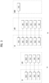
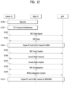
- FIG. 12 shows connection management captured in the TR document (3GPP TR 38.836) related to Rel-17 NR SL and a procedure for path switching from direct to indirect.
- TR document 3GPP TR 38.836
- a remote UE needs to establish its own PDU session/DRB with a network before user plane data transmission.
- APC5 unicast link establishment procedure in terms of PC5-RRC of Rel-16 NR V2X may be reused to establish a secure unicast link for L2 UE-to-network relaying between the remote UE and a relay UE before the remote UE establishes a Uu RRC connection with the network through the relay UE.
- a PC5 L2 configuration for transmission between the remote UE and the UE-to-network relay UE may be based on an RLC/MAC configuration defined in the standard. Establishment of Uu SRB1/SRB2 and DRB of the remote UE complies with a legacy Uu configuration procedure for L2 UE-to-network relay.
- a high-level connection establishment procedure shown in FIG. 12 is applied to the L2 UE-to-network relay.
- the remote and relay UEs may perform a discovery procedure and establish a PC5-RRC connection in operation S1201 based on the existing Rel-16 procedure.
- the remote UE may transmit a first RRC message (i.e., RRCSetupRequest) for connection establishment with the gNB through the relay UE by using a default L2 configuration of PC5.
- the gNB responds to the remote UE with an RRCSetup message (S1203).
- Transmission of RRCSetup to the remote UE uses a default configuration of PC5.
- the relay UE does not start in RRC_CONNECTED, the relay UE needs to perform its own connection setup upon receiving a message about the default L2 configuration of PC5. In this operation, details for the relay UE to transmit the RRCSetupRequest/RRCSetup message to the remote UE may be discussed in stage WI.
- the gNB and the relay UE perform a relay channel setup procedure via Uu.
- the relay/remote UE establishes an RLC channel for relaying SRB1 with the remote UE via PC5.
- a relay channel for SRB1 is prepared.
- the remote UE SRB1 message (e.g., RRCSetupComplete message) is transmitted to the gNB via the relay UE by using the SRB1 relay channel via PC5.
- the remote UE performs RRC connection via Uu.
- the remote UE and the gNB configure security according to a legacy procedure, and a security message is transmitted through the relay UE.
- the gNB configures an additional RLC channel between the gNB and the relay UE for traffic relay.
- the relay/remote UE configures an RLC channel between the remote UE and the relay UE for traffic relay.
- the gNB transmits RRCReconfiguration to the remote UE through the relay UE to configure relay SRB2/DRB.
- the remote UE transmits RRCReconfigurationComplete in response to the gNB through the relay UE.
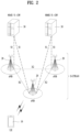
- FIG. 13 illustrates direct to indirect path switching.
- the procedure in FIG. 13 may be used when a remote UE switches to an indirect relay UE.
- the remote UE measures/discovers a candidate relay UE and then reports one or several candidate relay UEs.
- the remote UE may filter out an appropriate relay UE that meets higher layer standard during reporting.
- the report may include the ID and SL RSRP information of the relay UE, and in this case, the PC5 measurement details may be determined later.
- the gNB determines to switch to a target relay UE and the target (re)configuration is optionally transmitted to the relay UE.
- the RRC reconfiguration message for the remote UE may include the ID of the target relay UE, target Uu, and PC5 configuration.
- the remote UE feeds back RRCReconfigurationComplete to the gNB via a target path by using the target configuration provided in RRCReconfiguration.
- a method for configuring the aforementioned SL DRX is determined in a direction specific manner, and a TX UE determines the SL DRX of an RX UE.
- the RX UE may transmit a preferred SL DRX to the TX UE through SL assistance information.
- a service gNB of the TX UE determines SL DRX of the RX UE.
- the TX UE determines the SL DRX of the RX UE.
- the method of determining the SL DRX may be different, and embodiments of the present disclosure related thereto will be described below.
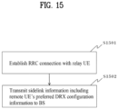
- a remote User Equipment may establish a Radio Resource Control (RRC) connection with a relay UE (S1501 of FIG. 15 ), and transmit side link information including preferred DRX configuration information of the remote UE to a base station (S1502).
- RRC Radio Resource Control
- the relay UE may establish an RRC connection with the base station, and the present disclosure is not limited by an RRC connection establishment sequence with each of the base station and the relay UE.
- the remote UE may directly receive an SL DRX configuration of the relay UE and an SL DRX configuration of the remote UE from the base station, and apply the SL DRX configuration of the remote UE.
- the remote UE may directly transmit the preferred DRX configuration information to the base station. The above operations may be based on that the remote UE recognizes that both a direct link to the base station and an indirect link to the base station via the relay UE may use an active multi-path.
- each of the remote UE and the relay UE may directly notify the gNB of (multiple) SL DRX configuration preferred by itself as an RX UE through an AUI/SUI (SidelinkUEInformation) message or the like.
- the gNB may directly configure an SL DRX to each of the remote UE and the relay UE.
- the gNB may receive a preferred SL DRX from the remote UE and directly configure an SL DRX to be used by the remote UE directly to each of the remote UE and the relay UE.
- the gNB may receive the preferred SL DRX from the relay UE and directly configure the SL DRX to be used by the relay UE to each of the remote UE and the relay UE.
- the gNB directly receives a preferred SL DRX configuration from each of the remote UE and the relay UE, and inform the remote UE and the relay UE of an SL DRX, which is to be used by the remote UE, through the relay UE in a manner similar to the existing one.
- the SL DRX to be used by the relay UE may also be notified to the remote UE and the relay UE via the remote UE.
- the remote UE may receive the SL DRX configuration from the base station via the relay UE based on that the remote UE is unable to perform direct transmission/reception with the base station.
- the remote UE may transmit the preferred DRX configuration information to the base station via the relay UE.
- the inability of the direction transmission/reception with the base station may include a case where the remote UE is out coverage or a case where the remote UE is RRC_CONNECTED with a base station other than the above-described base station.
- the remote UE may operate in resource allocation mode 2. That is, even when the remote UE and/or the relay UE operate in mode 2, the gNB may determine SL DRX of the remote UE and/or the relay UE. For example, even when the remote UE and/or the relay UE are RRC_CONNECTED and operate in mode 2, the gNB may directly configure the SL DRX for SL alignment with a Uu link of the remote UE and/or the relay UE, or in order to optimize the latency of a message transmitted via a relay. Of course, the remote UE (and/or the relay UE) may operate in resource allocation mode 1 in an existing manner.
- the remote UE may recognize that it is possible to use the multi-path when the base station separately configures a Uu bearer for the multi-path or an SL bearer for the multi-path. That is, when the gNB separately configures the U bearer for the multi-path, and when the SL bearer for the multi-path is separately configured, the remote UE may recognize that it is possible to use the multi-path link through the relay UE.
- the remote UE may recognize that it is possible to use multi-path when the base station has configure an SL bearer associated with (mapped to) the bearer of the Uu link.
- the remote UE may recognize that it is possible to use multi-path when the RRC configuration to require the base station to establish an SL connection with the relay UE includes an indicator to maintain the current Uu link. That is, if the RRC configuration to establish the SL connection with the relay UE includes an indication to maintain the current Uu link (notifying that multi-path connection is possible), the remote UE may recognize that it is possible for the remote UE to use the multi-path link through the relay UE.
- the remote UE may recognize that it is possible for the remote UE to use a multi-path link through the relay UE.
- the remote UE may inform the relay UE that it is possible to use the multi-path. That is, the relay UE may recognize that the remote UE connected to the relay UE is capable of the multi-path operation. The way to know this is that the gNB may give indication to the relay UE, or that the remote UE may inform the relay UE that the remote UE is capable of the multi-path operation (that the configuration for this purpose is received).
- the remote UE device includes at least one processor and at least one computer memory operably connected to the at least one processor and storing instructions causing the at least one processor to perform operations when executed.
- the operations include establishing a Radio Resource Control (RRC) connection with a relay UE by the remote UE; and transmitting sidelink information including preferred DRX configuration information of the remote UE to the base station by the remote UE.
- RRC Radio Resource Control
- the remote UE may receive SL DRX configuration of the relay UE and SL DRX configuration of the remote UE directly from the base station and apply the SL DRX configuration of the remote UE.
- the above-described multi-path may have a connection configured according to an embodiment described below.
- a method of configuring a multi-path connection through a sidelink relay in the following may be used independently of the above-described embodiment.
- a direct U link may be considered as a first link. That is, a remote UE may establish a multi-path via a relay UE after establishing a direct link first. Whether the remote UE may perform a multi-path configuration may be determined by capability of the remote UE and/or a configuration of a gNB. In this case, the gNB may configure the remote UE to find a relay UE for an indirect connection (measurement & report). This is different from the existing configuration for the relay, and a value different from an RSRP threshold value for selecting the existing relay UE may be set.
- the remote UE may report only a candidate relay UE having the same cell ID (PCI and/or NGCI) as the direct link to the gNB. This is because the multi-path may be performed for the same gNB.
- PCI and/or NGCI cell ID
- the gNB may select one relay UE to be used by the remote UE for a multi-path connection and inform the remote UE of it.
- the remote UE established an SL connection with the relay UE selected by the gNB, and in this process, may inform the relay UE of its cell ID (Pcell, NGcell). If the relay UE is in RRC_IDLE/INACTIVE state, the relay UE may have to preferentially access the same cell as the cell ID informed by the remote UE.
- the RRC_IDLE/INACTIVE relay UE determines several cells as candidate cells that are suitable (or acceptable) by performing a cell search and measuring signal strength, if a cell ID given by the remote UE is included in the candidate cell, it is necessary to perform an access to the corresponding cell. If the cell ID informed from the remote UE is not included the suitable(/acceptable) candidate cell ID found by the relay UE, the corresponding relay UE may determine that it is unable to access the same cell as the remote, and may have to inform the remote UE of this. In this case, the relay UE may also transmit a cause message failing in Uu connection.
- the remote UE has established an SL connection for multi-path with the relay UE selected by the gNB, if the remote UE is reported from the relay UE that the corresponding relay UE failed to access the gNB of the same cell as the remote UE, the remote UE may have to inform the gNB of this. The gNB may select another relay UE based on this and inform the remote UE of it again.
- FIG. 16 illustrates a communication system 1 applied to the present disclosure.
- a communication system 1 applied to the present disclosure includes wireless devices, BSs, and a network.
- the wireless devices represent devices performing communication using RAT (e.g., 5G NR or LTE) and may be referred to as communication/radio/5G devices.
- the wireless devices may include, without being limited to, a robot 100a, vehicles 100b-1 and 100b-2, an extended reality (XR) device 100c, a hand-held device 100d, a home appliance 100e, an Internet of things (IoT) device 100f, and an artificial intelligence (AI) device/server 400.
- the vehicles may include a vehicle having a wireless communication function, an autonomous driving vehicle, and a vehicle capable of performing communication between vehicles.
- the vehicles may include an unmanned aerial vehicle (UAV) (e.g., a drone).
- UAV unmanned aerial vehicle
- the XR device may include an augmented reality (AR)/virtual reality (VR)/mixed reality (MR) device and may be implemented in the form of a head-mounted device (HMD), a head-up display (HUD) mounted in a vehicle, a television, a smartphone, a computer, a wearable device, a home appliance device, a digital signage, a vehicle, a robot, etc.
- the hand-held device may include a smartphone, a smartpad, a wearable device (e.g., a smartwatch or a smartglasses), and a computer (e.g., a notebook).
- the home appliance may include a TV, a refrigerator, and a washing machine.
- the IoT device may include a sensor and a smartmeter.
- the BSs and the network may be implemented as wireless devices and a specific wireless device 200a may operate as a BS/network node with respect to other wireless devices.
- the wireless devices 100a to 100f may be connected to the network 300 via the BSs 200.
- An AI technology may be applied to the wireless devices 100a to 100f and the wireless devices 100a to 100f may be connected to the AI server 400 via the network 300.
- the network 300 may be configured using a 3G network, a 4G (e.g., LTE) network, or a 5G (e.g., NR) network.
- the wireless devices 100a to 100f may communicate with each other through the BSs 200/network 300, the wireless devices 100a to 100f may perform direct communication (e.g., sidelink communication) with each other without passing through the BSs/network.
- the vehicles 100b-1 and 100b-2 may perform direct communication (e.g. V2V/V2X communication).
- the IoT device e.g., a sensor
- Wireless communication/connections 150a, 150b, or 150c may be established between the wireless devices 100a to 100f/BS 200, or BS 200/BS 200.
- the wireless communication/connections may be established through various RATs (e.g., 5G NR) such as UL/DL communication 150a, sidelink communication 150b (or, D2D communication), or inter BS communication (e.g. relay, integrated access backhaul (IAB)).
- the wireless devices and the BSs/the wireless devices may transmit/receive radio signals to/from each other through the wireless communication/connections 150a and 150b.
- the wireless communication/connections 150a and 150b may transmit/receive signals through various physical channels.
- various configuration information configuring processes various signal processing processes (e.g., channel encoding/decoding, modulation/demodulation, and resource mapping/demapping), and resource allocating processes, for transmitting/receiving radio signals, may be performed based on the various proposals of the present disclosure.
- various signal processing processes e.g., channel encoding/decoding, modulation/demodulation, and resource mapping/demapping
- resource allocating processes for transmitting/receiving radio signals
- FIG. 17 illustrates wireless devices applicable to the present disclosure.
- a first wireless device 100 and a second wireless device 200 may transmit radio signals through a variety of RATs (e.g., LTE and NR).
- ⁇ the first wireless device 100 and the second wireless device 200 ⁇ may correspond to ⁇ the wireless device 100x and the BS 200 ⁇ and/or ⁇ the wireless device 100x and the wireless device 100x ⁇ of FIG. 14 .
- the first wireless device 100 may include one or more processors 102 and one or more memories 104 and additionally further include one or more transceivers 106 and/or one or more antennas 108.
- the processor(s) 102 may control the memory(s) 104 and/or the transceiver(s) 106 and may be configured to implement the descriptions, functions, procedures, proposals, methods, and/or operational flowcharts disclosed in this document.
- the processor(s) 102 may process information within the memory(s) 104 to generate first information/signals and then transmit radio signals including the first information/signals through the transceiver(s) 106.
- the processor(s) 102 may receive radio signals including second information/signals through the transceiver 106 and then store information obtained by processing the second information/signals in the memory(s) 104.
- the memory(s) 104 may be connected to the processor(s) 102 and may store a variety of information related to operations of the processor(s) 102.
- the memory(s) 104 may store software code including commands for performing a part or the entirety of processes controlled by the processor(s) 102 or for performing the descriptions, functions, procedures, proposals, methods, and/or operational flowcharts disclosed in this document.
- the processor(s) 102 and the memory(s) 104 may be a part of a communication modem/circuit/chip designed to implement RAT (e.g., LTE or NR).
- the transceiver(s) 106 may be connected to the processor(s) 102 and transmit and/or receive radio signals through one or more antennas 108.
- Each of the transceiver(s) 106 may include a transmitter and/or a receiver.
- the transceiver(s) 106 may be interchangeably used with Radio Frequency (RF) unit(s).
- the wireless device may represent a communication modem/circuit/chip.
- the second wireless device 200 may include one or more processors 202 and one or more memories 204 and additionally further include one or more transceivers 206 and/or one or more antennas 208.
- the processor(s) 202 may control the memory(s) 204 and/or the transceiver(s) 206 and may be configured to implement the descriptions, functions, procedures, proposals, methods, and/or operational flowcharts disclosed in this document.
- the processor(s) 202 may process information within the memory(s) 204 to generate third information/signals and then transmit radio signals including the third information/signals through the transceiver(s) 206.
- the processor(s) 202 may receive radio signals including fourth information/signals through the transceiver(s) 106 and then store information obtained by processing the fourth information/signals in the memory(s) 204.
- the memory(s) 204 may be connected to the processor(s) 202 and may store a variety of information related to operations of the processor(s) 202.
- the memory(s) 204 may store software code including commands for performing a part or the entirety of processes controlled by the processor(s) 202 or for performing the descriptions, functions, procedures, proposals, methods, and/or operational flowcharts disclosed in this document.
- the processor(s) 202 and the memory(s) 204 may be a part of a communication modem/circuit/chip designed to implement RAT (e.g., LTE or NR).
- the transceiver(s) 206 may be connected to the processor(s) 202 and transmit and/or receive radio signals through one or more antennas 208.
- Each of the transceiver(s) 206 may include a transmitter and/or a receiver.
- the transceiver(s) 206 may be interchangeably used with RF unit(s).
- the wireless device may represent a communication modem/circuit/chip.
- One or more protocol layers may be implemented by, without being limited to, one or more processors 102 and 202.
- the one or more processors 102 and 202 may implement one or more layers (e.g., functional layers such as PHY, MAC, RLC, PDCP, RRC, and SDAP).
- the one or more processors 102 and 202 may generate one or more Protocol Data Units (PDUs) and/or one or more service data unit (SDUs) according to the descriptions, functions, procedures, proposals, methods, and/or operational flowcharts disclosed in this document.
- PDUs Protocol Data Units
- SDUs service data unit
- the one or more processors 102 and 202 may generate messages, control information, data, or information according to the descriptions, functions, procedures, proposals, methods, and/or operational flowcharts disclosed in this document.
- the one or more processors 102 and 202 may generate signals (e.g., baseband signals) including PDUs, SDUs, messages, control information, data, or information according to the descriptions, functions, procedures, proposals, methods, and/or operational flowcharts disclosed in this document and provide the generated signals to the one or more transceivers 106 and 206.
- the one or more processors 102 and 202 may receive the signals (e.g., baseband signals) from the one or more transceivers 106 and 206 and acquire the PDUs, SDUs, messages, control information, data, or information according to the descriptions, functions, procedures, proposals, methods, and/or operational flowcharts disclosed in this document.
- signals e.g., baseband signals
- the one or more processors 102 and 202 may be referred to as controllers, microcontrollers, microprocessors, or microcomputers.
- the one or more processors 102 and 202 may be implemented by hardware, firmware, software, or a combination thereof.
- ASICs application specific integrated circuits
- DSPs digital signal processors
- DSPDs digital signal processing devices
- PLDs programmable logic devices
- FPGAs field programmable gate arrays
- the descriptions, functions, procedures, proposals, methods, and/or operational flowcharts disclosed in this document may be implemented using firmware or software and the firmware or software may be configured to include the modules, procedures, or functions.
- Firmware or software configured to perform the descriptions, functions, procedures, proposals, methods, and/or operational flowcharts disclosed in this document may be included in the one or more processors 102 and 202 or stored in the one or more memories 104 and 204 so as to be driven by the one or more processors 102 and 202.
- the descriptions, functions, procedures, proposals, methods, and/or operational flowcharts disclosed in this document may be implemented using firmware or software in the form of code, commands, and/or a set of commands.
- the one or more memories 104 and 204 may be connected to the one or more processors 102 and 202 and store various types of data, signals, messages, information, programs, code, instructions, and/or commands.
- the one or more memories 104 and 204 may be configured by read-only memories (ROMs), random access memories (RAMs), electrically erasable programmable read-only memories (EPROMs), flash memories, hard drives, registers, cash memories, computer-readable storage media, and/or combinations thereof.
- the one or more memories 104 and 204 may be located at the interior and/or exterior of the one or more processors 102 and 202.
- the one or more memories 104 and 204 may be connected to the one or more processors 102 and 202 through various technologies such as wired or wireless connection.
- the one or more transceivers 106 and 206 may transmit user data, control information, and/or radio signals/channels, mentioned in the methods and/or operational flowcharts of this document, to one or more other devices.
- the one or more transceivers 106 and 206 may receive user data, control information, and/or radio signals/channels, mentioned in the descriptions, functions, procedures, proposals, methods, and/or operational flowcharts disclosed in this document, from one or more other devices.
- the one or more transceivers 106 and 206 may be connected to the one or more processors 102 and 202 and transmit and receive radio signals.
- the one or more processors 102 and 202 may perform control so that the one or more transceivers 106 and 206 may transmit user data, control information, or radio signals to one or more other devices.
- the one or more processors 102 and 202 may perform control so that the one or more transceivers 106 and 206 may receive user data, control information, or radio signals from one or more other devices.
- the one or more transceivers 106 and 206 may be connected to the one or more antennas 108 and 208 and the one or more transceivers 106 and 206 may be configured to transmit and receive user data, control information, and/or radio signals/channels, mentioned in the descriptions, functions, procedures, proposals, methods, and/or operational flowcharts disclosed in this document, through the one or more antennas 108 and 208.
- the one or more antennas may be a plurality of physical antennas or a plurality of logical antennas (e.g., antenna ports).
- the one or more transceivers 106 and 206 may convert received radio signals/channels etc.
- the one or more transceivers 106 and 206 may convert the user data, control information, radio signals/channels, etc. processed using the one or more processors 102 and 202 from the base band signals into the RF band signals.
- the one or more transceivers 106 and 206 may include (analog) oscillators and/or filters.
- FIG. 18 illustrates a vehicle or an autonomous driving vehicle applied to the present disclosure.
- the vehicle or autonomous driving vehicle may be implemented by a mobile robot, a car, a train, a manned/unmanned aerial vehicle (AV), a ship, etc.
- AV manned/unmanned aerial vehicle
- a vehicle or autonomous driving vehicle 100 may include an antenna unit 108, a communication unit 110, a control unit 120, a driving unit 140a, a power supply unit 140b, a sensor unit 140c, and an autonomous driving unit 140d.
- the antenna unit 108 may be configured as a part of the communication unit 110.
- the communication unit 110 may transmit and receive signals (e.g., data and control signals) to and from external devices such as other vehicles, BSs (e.g., gNBs and road side units), and servers.
- the control unit 120 may perform various operations by controlling elements of the vehicle or the autonomous driving vehicle 100.
- the control unit 120 may include an ECU.
- the driving unit 140a may cause the vehicle or the autonomous driving vehicle 100 to drive on a road.
- the driving unit 140a may include an engine, a motor, a powertrain, a wheel, a brake, a steering device, etc.
- the power supply unit 140b may supply power to the vehicle or the autonomous driving vehicle 100 and include a wired/wireless charging circuit, a battery, etc.
- the sensor unit 140c may acquire a vehicle state, ambient environment information, user information, etc.
- the sensor unit 140c may include an inertial measurement unit (IMU) sensor, a collision sensor, a wheel sensor, a speed sensor, a slope sensor, a weight sensor, a heading sensor, a position module, a vehicle forward/backward sensor, a battery sensor, a fuel sensor, a tire sensor, a steering sensor, a temperature sensor, a humidity sensor, an ultrasonic sensor, an illumination sensor, a pedal position sensor, etc.
- IMU inertial measurement unit
- the autonomous driving unit 140d may implement technology for maintaining a lane on which a vehicle is driving, technology for automatically adjusting speed, such as adaptive cruise control, technology for autonomously driving along a determined path, technology for driving by automatically setting a path if a destination is set, and the like.
- the communication unit 110 may receive map data, traffic information data, etc. from an external server.
- the autonomous driving unit 140d may generate an autonomous driving path and a driving plan from the obtained data.
- the control unit 120 may control the driving unit 140a such that the vehicle or the autonomous driving vehicle 100 may move along the autonomous driving path according to the driving plan (e.g., speed/direction control).
- the communication unit 110 may aperiodically/periodically acquire recent traffic information data from the external server and acquire surrounding traffic information data from neighboring vehicles.
- the sensor unit 140c may obtain a vehicle state and/or surrounding environment information.
- the autonomous driving unit 140d may update the autonomous driving path and the driving plan based on the newly obtained data/information.
- the communication unit 110 may transfer information about a vehicle position, the autonomous driving path, and/or the driving plan to the external server.
- the external server may predict traffic information data using AI technology, etc., based on the information collected from vehicles or autonomous driving vehicles and provide the predicted traffic information data to the vehicles or the autonomous driving vehicles.
- FIG. 19 illustrates a vehicle applied to the present disclosure.
- the vehicle may be implemented as a transport means, an aerial vehicle, a ship, etc.
- a vehicle 100 may include a communication unit 110, a control unit 120, a memory unit 130, an I/O unit 140a, and a positioning unit 140b.
- the communication unit 110 may transmit and receive signals (e.g., data and control signals) to and from external devices such as other vehicles or BSs.
- the control unit 120 may perform various operations by controlling constituent elements of the vehicle 100.
- the memory unit 130 may store data/parameters/programs/code/commands for supporting various functions of the vehicle 100.
- the I/O unit 140a may output an AR/VR object based on information within the memory unit 130.
- the I/O unit 140a may include an HUD.
- the positioning unit 140b may acquire information about the position of the vehicle 100.
- the position information may include information about an absolute position of the vehicle 100, information about the position of the vehicle 100 within a traveling lane, acceleration information, and information about the position of the vehicle 100 from a neighboring vehicle.
- the positioning unit 140b may include a GPS and various sensors.
- the communication unit 110 of the vehicle 100 may receive map information and traffic information from an external server and store the received information in the memory unit 130.
- the positioning unit 140b may obtain the vehicle position information through the GPS and various sensors and store the obtained information in the memory unit 130.
- the control unit 120 may generate a virtual object based on the map information, traffic information, and vehicle position information and the I/O unit 140a may display the generated virtual object in a window in the vehicle (1410 and 1420).
- the control unit 120 may determine whether the vehicle 100 normally drives within a traveling lane, based on the vehicle position information. If the vehicle 100 abnormally exits from the traveling lane, the control unit 120 may display a warning on the window in the vehicle through the I/O unit 140a. In addition, the control unit 120 may broadcast a warning message regarding driving abnormity to neighboring vehicles through the communication unit 110. According to situation, the control unit 120 may transmit the vehicle position information and the information about driving/vehicle abnormality to related organizations.
- FIG. 20 illustrates an XR device applied to the present disclosure.
- the XR device may be implemented by an HMD, an HUD mounted in a vehicle, a television, a smartphone, a computer, a wearable device, a home appliance, a digital signage, a vehicle, a robot, etc.
- an XR device 100a may include a communication unit 110, a control unit 120, a memory unit 130, an I/O unit 140a, a sensor unit 140b, and a power supply unit 140c.
- the communication unit 110 may transmit and receive signals (e.g., media data and control signals) to and from external devices such as other wireless devices, hand-held devices, or media servers.
- the media data may include video, images, and sound.
- the control unit 120 may perform various operations by controlling constituent elements of the XR device 100a.
- the control unit 120 may be configured to control and/or perform procedures such as video/image acquisition, (video/image) encoding, and metadata generation and processing.
- the memory unit 130 may store data/parameters/programs/code/commands needed to drive the XR device 100a/generate XR object.
- the I/O unit 140a may obtain control information and data from the exterior and output the generated XR object.
- the I/O unit 140a may include a camera, a microphone, a user input unit, a display unit, a speaker, and/or a haptic module.
- the sensor unit 140b may obtain an XR device state, surrounding environment information, user information, etc.
- the sensor unit 140b may include a proximity sensor, an illumination sensor, an acceleration sensor, a magnetic sensor, a gyro sensor, an inertial sensor, an RGB sensor, an IR sensor, a fingerprint recognition sensor, an ultrasonic sensor, a light sensor, a microphone and/or a radar.
- the power supply unit 140c may supply power to the XR device 100a and include a wired/wireless charging circuit, a battery, etc.
- the memory unit 130 of the XR device 100a may include information (e.g., data) needed to generate the XR object (e.g., an AR/VR/MR object).
- the I/O unit 140a may receive a command for manipulating the XR device 100a from a user and the control unit 120 may drive the XR device 100a according to a driving command of a user. For example, when a user desires to watch a film or news through the XR device 100a, the control unit 120 transmits content request information to another device (e.g., a hand-held device 100b) or a media server through the communication unit 130.
- another device e.g., a hand-held device 100b
- a media server e.g., a media server
- the communication unit 130 may download/stream content such as films or news from another device (e.g., the hand-held device 100b) or the media server to the memory unit 130.
- the control unit 120 may control and/or perform procedures such as video/image acquisition, (video/image) encoding, and metadata generation/processing with respect to the content and generate/output the XR object based on information about a surrounding space or a real object obtained through the I/O unit 140a/sensor unit 140b.
- the XR device 100a may be wirelessly connected to the hand-held device 100b through the communication unit 110 and the operation of the XR device 100a may be controlled by the hand-held device 100b.
- the hand-held device 100b may operate as a controller of the XR device 100a.
- the XR device 100a may obtain information about a 3D position of the hand-held device 100b and generate and output an XR object corresponding to the hand-held device 100b.
- FIG. 21 illustrates a robot applied to the present disclosure.
- the robot may be categorized into an industrial robot, a medical robot, a household robot, a military robot, etc., according to a used purpose or field.
- a robot 100 may include a communication unit 110, a control unit 120, a memory unit 130, an I/O unit 140a, a sensor unit 140b, and a driving unit 140c.
- the blocks 110 to 130/140a to 140c correspond to the blocks 110 to 130/140 of FIG. 15 , respectively.
- the communication unit 110 may transmit and receive signals (e.g., driving information and control signals) to and from external devices such as other wireless devices, other robots, or control servers.
- the control unit 120 may perform various operations by controlling constituent elements of the robot 100.
- the memory unit 130 may store data/parameters/programs/code/commands for supporting various functions of the robot 100.
- the I/O unit 140a may obtain information from the exterior of the robot 100 and output information to the exterior of the robot 100.
- the I/O unit 140a may include a camera, a microphone, a user input unit, a display unit, a speaker, and/or a haptic module.
- the sensor unit 140b may obtain internal information of the robot 100, surrounding environment information, user information, etc.
- the sensor unit 140b may include a proximity sensor, an illumination sensor, an acceleration sensor, a magnetic sensor, a gyro sensor, an inertial sensor, an IR sensor, a fingerprint recognition sensor, an ultrasonic sensor, a light sensor, a microphone, a radar, etc.
- the driving unit 140c may perform various physical operations such as movement of robot joints. In addition, the driving unit 140c may cause the robot 100 to travel on the road or to fly.
- the driving unit 140c may include an actuator, a motor, a wheel, a brake, a propeller, etc.
- FIG. 22 illustrates an AI device applied to the present disclosure.
- the AI device may be implemented by a fixed device or a mobile device, such as a TV, a projector, a smartphone, a PC, a notebook, a digital broadcast terminal, a tablet PC, a wearable device, a Set Top Box (STB), a radio, a washing machine, a refrigerator, a digital signage, a robot, a vehicle, etc.
- an AI device 100 may include a communication unit 110, a control unit 120, a memory unit 130, an I/O unit 140a/140b, a learning processor unit 140c, and a sensor unit 140d.
- the blocks 110 to 130/140a to 140d correspond to blocks 110 to 130/140 of FIG. 15 , respectively.
- the control unit 120 may determine at least one feasible operation of the AI device 100, based on information which is determined or generated using a data analysis algorithm or a machine learning algorithm.
- the control unit 120 may perform an operation determined by controlling constituent elements of the AI device 100. For example, the control unit 120 may request, search, receive, or use data of the learning processor unit 140c or the memory unit 130 and control the constituent elements of the AI device 100 to perform a predicted operation or an operation determined to be preferred among at least one feasible operation.
- the control unit 120 may collect history information including the operation contents of the AI device 100 and operation feedback by a user and store the collected information in the memory unit 130 or the learning processor unit 140c or transmit the collected information to an external device such as an AI server (400 of FIG. 14 ). The collected history information may be used to update a learning model.
- the input unit 140a may acquire various types of data from the exterior of the AI device 100.
- the input unit 140a may acquire learning data for model learning, and input data to which the learning model is to be applied.
- the input unit 140a may include a camera, a microphone, and/or a user input unit.
- the output unit 140b may generate output related to a visual, auditory, or tactile sense.
- the output unit 140b may include a display unit, a speaker, and/or a haptic module.
- the sensing unit 140 may obtain at least one of internal information of the AI device 100, surrounding environment information of the AI device 100, and user information, using various sensors.
Landscapes
- Engineering & Computer Science (AREA)
- Computer Networks & Wireless Communication (AREA)
- Signal Processing (AREA)
- Mobile Radio Communication Systems (AREA)
Applications Claiming Priority (3)
| Application Number | Priority Date | Filing Date | Title |
|---|---|---|---|
| KR20220058492 | 2022-05-12 | ||
| KR20220061592 | 2022-05-19 | ||
| PCT/KR2023/006415 WO2023219441A1 (ko) | 2022-05-12 | 2023-05-11 | 무선통신시스템에서 멀티 패스 릴레이 동작을 위한 사이드링크 drx configuration에 관련된 ue의 동작 방법 |
Publications (1)
| Publication Number | Publication Date |
|---|---|
| EP4525550A1 true EP4525550A1 (de) | 2025-03-19 |
Family
ID=88730714
Family Applications (1)
| Application Number | Title | Priority Date | Filing Date |
|---|---|---|---|
| EP23803864.0A Pending EP4525550A1 (de) | 2022-05-12 | 2023-05-11 | Benutzergerätebetriebsverfahren im zusammenhang mit sidelink-drx-konfiguration für mehrpfadrelaisbetrieb in einem drahtloskommunikationssystem |
Country Status (4)
| Country | Link |
|---|---|
| US (1) | US20260020099A1 (de) |
| EP (1) | EP4525550A1 (de) |
| CN (1) | CN119563375A (de) |
| WO (1) | WO2023219441A1 (de) |
Families Citing this family (1)
| Publication number | Priority date | Publication date | Assignee | Title |
|---|---|---|---|---|
| WO2025105994A1 (en) * | 2023-11-17 | 2025-05-22 | Telefonaktiebolaget Lm Ericsson (Publ) | Methods, ncr, network node and ue for handling drx configurations in a communications network |
Family Cites Families (4)
| Publication number | Priority date | Publication date | Assignee | Title |
|---|---|---|---|---|
| WO2021127485A1 (en) * | 2019-12-19 | 2021-06-24 | Convida Wireless LLC | Paging remote ue using a relay |
| KR20210125421A (ko) * | 2020-04-07 | 2021-10-18 | 주식회사 케이티 | 사이드링크 통신을 제어하는 방법 및 그 장치 |
| WO2021219212A1 (en) * | 2020-04-29 | 2021-11-04 | Huawei Technologies Co., Ltd. | Methods and devices for discontinueous reception operation on sidelink communication channel |
| WO2022027548A1 (en) * | 2020-08-07 | 2022-02-10 | Qualcomm Incorporated | Radio link failure in sidelink relay |
-
2023
- 2023-05-11 CN CN202380039724.4A patent/CN119563375A/zh active Pending
- 2023-05-11 US US18/865,244 patent/US20260020099A1/en active Pending
- 2023-05-11 EP EP23803864.0A patent/EP4525550A1/de active Pending
- 2023-05-11 WO PCT/KR2023/006415 patent/WO2023219441A1/ko not_active Ceased
Also Published As
| Publication number | Publication date |
|---|---|
| WO2023219441A1 (ko) | 2023-11-16 |
| US20260020099A1 (en) | 2026-01-15 |
| CN119563375A (zh) | 2025-03-04 |
Similar Documents
| Publication | Publication Date | Title |
|---|---|---|
| EP4383817A1 (de) | Verfahren zum betrieb eines entfernten benutzergeräts im zusammenhang mit pfadumschaltung und messberichterstattung in einem drahtloskommunikationssystem | |
| US12219649B2 (en) | Method of operating a UE related to sidelink DRX in a wireless communication system | |
| EP4373157A1 (de) | Betriebsverfahren im zusammenhang mit der übergabe in einem sidelink-relais in einem drahtloskommunikationssystem | |
| EP4408068A1 (de) | Verfahren und vorrichtung für betrieb im zusammenhang mit sidelink-drx und übergabe in einem drahtloskommunikationssystem | |
| EP4546872A1 (de) | Betriebsverfahren für benutzergerät im zusammenhang mit einem leerlaufrelais-benutzergerät in einem mehrpfadrelais in einem drahtloskommunikationssystem | |
| EP4274362B1 (de) | Verfahren und vorrichtung zum betrieb eines benutzergeräts im zusammenhang mit der übertragung von daten mit verschiedenen sl-drx-konfigurationen in einem drahtloskommunikationssystem | |
| US20250175865A1 (en) | Operation method of remote ue in path switching in wireless communication system | |
| EP4395450A1 (de) | Betriebsverfahren und -vorrichtung im zusammenhang mit pfadumschaltung und zeitgeber eines sidelink-remote-benutzergeräts in einem drahtloskommunikationssystem | |
| EP4525550A1 (de) | Benutzergerätebetriebsverfahren im zusammenhang mit sidelink-drx-konfiguration für mehrpfadrelaisbetrieb in einem drahtloskommunikationssystem | |
| US12047976B2 (en) | UE operation method related to discovery resource pool in wireless communication system | |
| EP4593514A1 (de) | Verfahren zum betrieb eines relais-ue in zusammenhang mit der konfiguration einer ue-zu-ue-relaisverbindung in einem drahtloskommunikationssystem | |
| US20260113612A1 (en) | Operating method of source remote ue related to ue-to-ue relay in wireless communication system | |
| EP4518564A1 (de) | Betriebsverfahren eines benutzergeräts im zusammenhang mit rlf in mehrpfadrelais in einem drahtloskommunikationssystem | |
| US20230388771A1 (en) | Method of operating sidelink remote ue in relation to path switching in wireless communication system | |
| EP4383928A1 (de) | Betriebsverfahren im zusammenhang mit der rrc-wiederherstellung in sidelink in einem drahtloskommunikationssystem | |
| EP4369810A1 (de) | Betriebsverfahren im zusammenhang mit der funkrufüberwachung in sidelink-relais in einem drahtloskommunikationssystem | |
| EP4408076A1 (de) | Verfahren zum betrieb eines remote-benutzergeräts im zusammenhang mit funkrufen in einem drahtloskommunikationssystem | |
| US20240407044A1 (en) | Operation method and device related to sidelink drx and initial transmission in wireless communication system | |
| EP4383907A1 (de) | Betriebsverfahren im zusammenhang mit einem ressourcenzuweisungsmodus und verbindungsaufbau eines sidelink-remote-benutzergeräts in einem drahtloskommunikationssystem | |
| EP4340454A1 (de) | Sib-assoziiertes betriebsverfahren und vorrichtung eines sidelink-fernbenutzergeräts und relaisbenutzergeräts in einem drahtloskommunikationssystem | |
| EP4546939A1 (de) | Verfahren für remote-ue-betrieb im zusammenhang mit einem verfahren zur indirekten verbindungsherstellung in einem mehrpfadrelais in einem drahtloskommunikationssystem | |
| US20250151157A1 (en) | Method and device for operating tx ue related to sl drx capability of base station in sidelink drx in wireless communication system | |
| EP4664973A1 (de) | Betriebsverfahren für relais-ue in zusammenhang mit strahlausfall in einem mehrpfad-relais in einem drahtloskommunikationssystem | |
| EP4664998A1 (de) | Betriebsverfahren eines relais-ue in zusammenhang mit der übergabe eines relais-ue in einem mehrpfad-relais in einem drahtloskommunikationssystem | |
| EP4440236A1 (de) | Betriebsverfahren in zusammenhang mit der rrc-rekonfiguration eines relais-ue in einem drahtloskommunikationssystem |
Legal Events
| Date | Code | Title | Description |
|---|---|---|---|
| STAA | Information on the status of an ep patent application or granted ep patent |
Free format text: STATUS: THE INTERNATIONAL PUBLICATION HAS BEEN MADE |
|
| PUAI | Public reference made under article 153(3) epc to a published international application that has entered the european phase |
Free format text: ORIGINAL CODE: 0009012 |
|
| STAA | Information on the status of an ep patent application or granted ep patent |
Free format text: STATUS: REQUEST FOR EXAMINATION WAS MADE |
|
| 17P | Request for examination filed |
Effective date: 20241128 |
|
| AK | Designated contracting states |
Kind code of ref document: A1 Designated state(s): AL AT BE BG CH CY CZ DE DK EE ES FI FR GB GR HR HU IE IS IT LI LT LU LV MC ME MK MT NL NO PL PT RO RS SE SI SK SM TR |
|
| DAV | Request for validation of the european patent (deleted) | ||
| DAX | Request for extension of the european patent (deleted) |