EP4525193A1 - Battery current collector disc and battery - Google Patents
Battery current collector disc and battery Download PDFInfo
- Publication number
- EP4525193A1 EP4525193A1 EP23851949.0A EP23851949A EP4525193A1 EP 4525193 A1 EP4525193 A1 EP 4525193A1 EP 23851949 A EP23851949 A EP 23851949A EP 4525193 A1 EP4525193 A1 EP 4525193A1
- Authority
- EP
- European Patent Office
- Prior art keywords
- connection portion
- current collector
- terminal
- collector plate
- battery
- Prior art date
- Legal status (The legal status is an assumption and is not a legal conclusion. Google has not performed a legal analysis and makes no representation as to the accuracy of the status listed.)
- Pending
Links
Images


Classifications
-
- H—ELECTRICITY
- H01—ELECTRIC ELEMENTS
- H01M—PROCESSES OR MEANS, e.g. BATTERIES, FOR THE DIRECT CONVERSION OF CHEMICAL ENERGY INTO ELECTRICAL ENERGY
- H01M50/00—Constructional details or processes of manufacture of the non-active parts of electrochemical cells other than fuel cells, e.g. hybrid cells
- H01M50/50—Current conducting connections for cells or batteries
- H01M50/572—Means for preventing undesired use or discharge
- H01M50/574—Devices or arrangements for the interruption of current
- H01M50/581—Devices or arrangements for the interruption of current in response to temperature
-
- H—ELECTRICITY
- H01—ELECTRIC ELEMENTS
- H01M—PROCESSES OR MEANS, e.g. BATTERIES, FOR THE DIRECT CONVERSION OF CHEMICAL ENERGY INTO ELECTRICAL ENERGY
- H01M50/00—Constructional details or processes of manufacture of the non-active parts of electrochemical cells other than fuel cells, e.g. hybrid cells
- H01M50/50—Current conducting connections for cells or batteries
- H01M50/531—Electrode connections inside a battery casing
-
- H—ELECTRICITY
- H01—ELECTRIC ELEMENTS
- H01M—PROCESSES OR MEANS, e.g. BATTERIES, FOR THE DIRECT CONVERSION OF CHEMICAL ENERGY INTO ELECTRICAL ENERGY
- H01M50/00—Constructional details or processes of manufacture of the non-active parts of electrochemical cells other than fuel cells, e.g. hybrid cells
- H01M50/50—Current conducting connections for cells or batteries
- H01M50/531—Electrode connections inside a battery casing
- H01M50/533—Electrode connections inside a battery casing characterised by the shape of the leads or tabs
-
- H—ELECTRICITY
- H01—ELECTRIC ELEMENTS
- H01M—PROCESSES OR MEANS, e.g. BATTERIES, FOR THE DIRECT CONVERSION OF CHEMICAL ENERGY INTO ELECTRICAL ENERGY
- H01M50/00—Constructional details or processes of manufacture of the non-active parts of electrochemical cells other than fuel cells, e.g. hybrid cells
- H01M50/50—Current conducting connections for cells or batteries
- H01M50/572—Means for preventing undesired use or discharge
- H01M50/574—Devices or arrangements for the interruption of current
- H01M50/583—Devices or arrangements for the interruption of current in response to current, e.g. fuses
-
- H—ELECTRICITY
- H01—ELECTRIC ELEMENTS
- H01M—PROCESSES OR MEANS, e.g. BATTERIES, FOR THE DIRECT CONVERSION OF CHEMICAL ENERGY INTO ELECTRICAL ENERGY
- H01M50/00—Constructional details or processes of manufacture of the non-active parts of electrochemical cells other than fuel cells, e.g. hybrid cells
- H01M50/50—Current conducting connections for cells or batteries
- H01M50/572—Means for preventing undesired use or discharge
- H01M50/584—Means for preventing undesired use or discharge for preventing incorrect connections inside or outside the batteries
- H01M50/59—Means for preventing undesired use or discharge for preventing incorrect connections inside or outside the batteries characterised by the protection means
- H01M50/593—Spacers; Insulating plates
-
- Y—GENERAL TAGGING OF NEW TECHNOLOGICAL DEVELOPMENTS; GENERAL TAGGING OF CROSS-SECTIONAL TECHNOLOGIES SPANNING OVER SEVERAL SECTIONS OF THE IPC; TECHNICAL SUBJECTS COVERED BY FORMER USPC CROSS-REFERENCE ART COLLECTIONS [XRACs] AND DIGESTS
- Y02—TECHNOLOGIES OR APPLICATIONS FOR MITIGATION OR ADAPTATION AGAINST CLIMATE CHANGE
- Y02E—REDUCTION OF GREENHOUSE GAS [GHG] EMISSIONS, RELATED TO ENERGY GENERATION, TRANSMISSION OR DISTRIBUTION
- Y02E60/00—Enabling technologies; Technologies with a potential or indirect contribution to GHG emissions mitigation
- Y02E60/10—Energy storage using batteries
Definitions
- the present application relates to battery technology, particularly to a battery current collector plate and a battery.
- a cylindrical lithium-ion battery typically includes a core inside the battery's case.
- a positive terminal is connected to positive tabs of the core through a positive current collector plate, and/or a negative terminal is connected to negative tabs of the core through a negative current collector plate, resulting in the positive terminal carrying a positive charge and the negative terminal carrying a negative charge.
- a current collector plate of a battery is a sheet-like integrally formed structure.
- the internal structural components of the battery generate significant heat over an extended period due to the high current conditions. It increases an internal pressure of the battery at high temperatures, ultimately leading to the battery exploding or the explosion-proof valve opening.
- an embodiment of the present application further provides a battery comprising a case, a core, one or more terminals, and the aforementioned battery current collector plate.
- the battery current collector plate is disposed inside the case, between the core and the terminal, and the tab connection portion of the battery current collector plate is electrically connected to the one or more tabs of the core, and the terminal connection portion of the battery current collector plate is electrically connected to the terminal.
- the terminal connection portion 2 and the tab connection portion 1 of the battery current collector plate are electrically connected through the fuse 3, allowing the terminal 30 to carry a charge.
- the internal temperature of the battery increases, causing the fuse 3 to melt. This prevents the battery from exploding or the explosion-proof valve from opening due to a short circuit, ensuring the battery's safety.
- the thickness of the battery current collector plate in this embodiment is not increased, meaning that the addition of the fuse 3 does not sacrifice the height of the core 20 to meet the requirements for electrical clearance specified in GB standards.
Landscapes
- Chemical & Material Sciences (AREA)
- Chemical Kinetics & Catalysis (AREA)
- Electrochemistry (AREA)
- General Chemical & Material Sciences (AREA)
- Connection Of Batteries Or Terminals (AREA)
Abstract
Description
- The present application relates to battery technology, particularly to a battery current collector plate and a battery.
- A cylindrical lithium-ion battery typically includes a core inside the battery's case. A positive terminal is connected to positive tabs of the core through a positive current collector plate, and/or a negative terminal is connected to negative tabs of the core through a negative current collector plate, resulting in the positive terminal carrying a positive charge and the negative terminal carrying a negative charge.
- Currently, a current collector plate of a battery is a sheet-like integrally formed structure. When a short circuit occurs in the battery, the internal structural components of the battery generate significant heat over an extended period due to the high current conditions. It increases an internal pressure of the battery at high temperatures, ultimately leading to the battery exploding or the explosion-proof valve opening.
- Therefore, there is an urgent need for a battery current collector plate and battery to address the above-mentioned technical issues.
- The purpose of the present application is to propose a battery current collector plate and battery that prevent the battery from exploding or the explosion-proof valve from opening due to a short circuit.
- To achieve this purpose, the present application employs the following technical solutions:
In a first aspect, an embodiment of the present application provides a battery current collector plate, comprising: - a tab connection portion configured to electrically connect to one or more tabs of a battery, wherein the tab connection portion represents an annular structure;
- a terminal connection portion configured to electrically connect to a terminal of the battery, wherein the terminal connection portion is disposed at a center of the tab connection portion, and an annular gap is formed between a circumferential edge of the terminal connection portion and an inner circumferential edge of the tab connection portion;
- one or more fuses, each having two ends respectively connected to the circumferential edge of the terminal connection portion and the inner circumferential edge of the tab connection portion.
- In a second aspect, an embodiment of the present application further provides a battery comprising a case, a core, one or more terminals, and the aforementioned battery current collector plate. The battery current collector plate is disposed inside the case, between the core and the terminal, and the tab connection portion of the battery current collector plate is electrically connected to the one or more tabs of the core, and the terminal connection portion of the battery current collector plate is electrically connected to the terminal.
- The battery current collector plate provided by the present application, when used, electrically connects the tab connection portion of the battery current collector plate to the tab of the battery and the terminal connection portion of the battery current collector plate to the terminal of the battery. Due to the formation of an electrical connection between the terminal connection portion and the tab connection portion through the fuse, the terminal is electrified. When a short circuit occurs, the internal temperature of the battery increases, causing the fuse to melt and breaking the electrical connection between the terminal connection portion and the tab connection portion. This prevents the battery from exploding or the explosion-proof valve from opening due to a short circuit, ensuring the battery's safety.
- The battery provided by the present application includes a case, core, terminal, and the aforementioned battery current collector plate. The battery current collector plate is positioned inside the case, between the core and the terminal. The tab connection portion of the battery current collector plate is electrically connected to the tab of the core, and the terminal connection portion of the battery current collector plate is electrically connected to the terminal. Due to the formation of an electrical connection between the terminal connection portion and the tab connection portion through the fuse, the terminal is electrified. When a short circuit occurs, the internal temperature of the battery increases, causing the fuse to melt and preventing the battery from exploding or the explosion-proof valve from opening, ensuring the battery's safety.
-
-
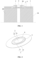
Figure 1 is a partial cross-sectional view of a battery provided by one or more embodiments of the present application. -
Figure 2 is a structural diagram of the battery current collector plate provided by one or more embodiments of the present application. -
Figure 3 is a rear view of the battery current collector plate provided by one or more embodiments of the present application. -
Figure 4 is a front view of the battery current collector plate provided by one or more embodiments of the present application. -
Figure 5 is a partial cross-sectional view of section A-A inFigure 4 . - In the figures:
- 10 - Case; 20 - Core; 30 - Terminal;
- 1 - Tab connection portion; 2 - Terminal connection portion; 3 - Fuse; 4 - Insulation part; 5 - Insulation layer;
- 11 - Second folding edge; 12 - Tab connection body; 21 - First folding edge; 22 - Terminal connection body.
- In the description of the present application, unless otherwise expressly stated and limited, terms such as "connected," "joined," and "fixed" should be broadly interpreted. For example, they can represent fixed connections, detachable connections, or integral connections; they can be mechanical connections or electrical connections; they can be direct connections or indirect connections through an intermediate medium; they can represent communication within two components or the interaction between two components.
- In the present application, unless otherwise expressly stated and limited, the phrase "above" or "below" the first feature from the second feature can include direct contact between the first and second features, or contact through another feature between them. Furthermore, the phrase "above," "on top of," or "on" the first feature from the second feature includes both the first feature being directly above the second feature and at an angle above, or it simply means that the first feature's horizontal height is higher than the second feature's height. The phrase "below," "beneath," or "underneath" the first feature from the second feature includes both the first feature being directly below the second feature and at an angle below, or it simply means that the first feature's horizontal height is lower than the second feature's height.
- In the description of this embodiment, terms such as "up," "down," "right," and other directional or positional relationships are based on the orientation or position shown in the drawings. They are used for descriptive convenience and simplification of the operation and do not indicate or imply that the indicated device or component must have a specific orientation, be constructed or operated in a specific orientation. Hence, they should not be understood as limitations on the present application. Additionally, terms such as "first" and "second" are used merely to distinguish between descriptions and do not imply any particular meaning.
- The following provides further detailed explanations of the technical solutions of the present application in conjunction with the drawings.
- In the related art, the current collector plate of a cylindrical lithium-ion battery is a sheet-like integrally formed structure. When a short circuit occurs in the battery, the circuit on the current collector plate remains conductive, maintaining the electrical connection between the tabs of the core and the terminal, and allowing current to continuously flow inside the battery. This results in severe overheating of the internal structural components inside the battery over an extended period due to the high current conditions, leading to the battery exploding or the explosion-proof valve opening.
- To address this issue, in this embodiment, a battery is provided in which the internal current collector plate of the battery breaks the circuit when a short circuit occurs, disconnecting the electrical connection between the tabs of the core and the terminal. This effectively interrupts the circuit, preventing severe overheating of the battery and avoiding the battery exploding or the explosion-proof valve opening.
- Specifically, the positive and negative terminals are led out from the same end of the battery.
- As shown in
Figure 1 , the battery of this embodiment includes acase 10, acore 20, one ormore terminals 30, and one or more battery current collector plates. The battery current collector plate is positioned inside thecase 10, between thecore 20 and thecorresponding terminal 30. One side of the battery current collector plate is electrically connected to theterminal 30, while the other side is electrically connected to the tabs of thecore 20. - Optionally, the battery includes one battery current collector plate, with the
terminal 30 being the positive terminal. The battery current collector plate is positioned between the positive tabs of thecore 20 and theterminal 30, allowing theterminal 30 to carry a positive charge. The negative tabs of thecore 20 is connected to thecase 10, allowing thecase 10 to carry a negative charge. - Optionally, the battery includes one battery current collector plate, with the
terminal 30 being the negative terminal. The battery current collector plate is positioned between the negative tabs of thecore 20 and theterminal 30, allowing thenegative terminal 30 to carry a negative charge. The positive tabs of thecore 20 is connected to thecase 10, allowing thecase 10 to carry a positive charge. - Optionally, the battery includes two battery current collector plates and two
terminals 30, with oneterminal 30 being the positive terminal and theother terminal 30 being the negative terminal. One battery current collector plate is positioned between the positive tabs of thecore 20 and the positive terminal, allowing the positive terminal to carry a positive charge. The other battery current collector plate is positioned between the negative tabs of thecore 20 and the negative terminal, allowing the negative terminal to carry a negative charge. - Specifically, as shown in
Figure 2 , the battery current collector plate provided by this embodiment includes atab connection portion 1, aterminal connection portion 2, and afuse 3. Thetab connection portion 1 is electrically connected to the tabs of the core 20, and it represents a ring-shaped structure. Theterminal connection portion 2 is electrically connected to theterminal 30 of the battery and positioned at the center of thetab connection portion 1, and an annular gap is formed between the circumferential edge of theterminal connection portion 2 and the inner circumferential edge of thetab connection portion 1. Thefuse 3 is connected, with its two ends connected to the circumferential edge of theterminal connection portion 2 and the inner circumferential edge of thetab connection portion 1 respectively. - The
terminal connection portion 2 and thetab connection portion 1 of the battery current collector plate are electrically connected through thefuse 3, allowing the terminal 30 to carry a charge. When a short circuit occurs, the internal temperature of the battery increases, causing thefuse 3 to melt. This prevents the battery from exploding or the explosion-proof valve from opening due to a short circuit, ensuring the battery's safety. At the same time, the thickness of the battery current collector plate in this embodiment is not increased, meaning that the addition of thefuse 3 does not sacrifice the height of the core 20 to meet the requirements for electrical clearance specified in GB standards. - The battery current collector plate provided by this embodiment also includes an
insulation part 4, which is placed in the space formed by theterminal connection portion 2, thetab connection portion 1, and thefuse 3. Theinsulation part 4 not only enhances the stability of the connection between theterminal connection portion 2 and thetab connection portion 1, but also acts as insulation protection, preventing the meltedfuse 3 from accidentally contacting adjacent metal components and re-establishing an electrical connection in the circuit. As shown inFigure 1 , the battery current collector plate includes thefuse 3 positioned within a small segment of the annular gap between theterminal connection portion 2 and thetab connection portion 1, and the remaining portion is occupied by theinsulation part 4. - Optionally,
multiple fuses 3 are installed, distributed evenly around the circumference of theterminal connection portion 2 of the battery current collector plate. In this embodiment, the number offuses 3 is preferably 1-3. - Specifically, as shown in
Figure 2 andFigure 5 , theterminal connection portion 2 forms afirst folding edge 21 by having its outer circumferential edge bent toward a side away from the tabs. Thetab connection portion 1 forms asecond folding edge 11 by having its inner circumferential edge bent toward the side away from the tabs. Thefuse 3 is connected between thefirst folding edge 21 and thesecond folding edge 11, and the space defined by the first and second folding edges 21, 22 and thefuse 3 forms a space where theinsulation part 4 is located. Thefuse 3 is connected to the end of thefirst folding edge 21 and the end of thesecond folding edge 11. Moreover, the arrangement of thefirst folding edge 21 and thesecond folding edge 11 allows theinsulation part 4 to be positioned on the side of thefuse 3 facing thecore 20, further preventing the meltedfuse 3 from accidentally contacting adjacent metal components and re-establishing an electrical connection in the circuit. - As shown in
Figure 2 andFigure 5 , theterminal connection portion 2 includes aterminal connection body 22, and thefirst folding edge 21 is connected to the outer circumferential edge of theterminal connection body 22. Theterminal connection body 22 is electrically connected to the terminal. Thetab connection portion 1 includes a ring-shapedtab connection body 12, and thesecond folding edge 11 is connected to the inner circumferential edge of thetab connection body 12. Thetab connection body 12 is electrically connected to the tabs. In this embodiment, theterminal connection body 22 and thefirst folding edge 21 are integrally formed, and thetab connection body 12 and thesecond folding edge 11 are integrally formed. Theterminal connection body 22 is welded to the end of the terminal 30, and thetab connection body 12 is welded to the tabs of thecore 20. - As shown in
Figure 5 , on the side facing the tabs, the surface of thetab connection portion 1, the surface of theterminal connection portion 2, and the surface of theinsulation part 4 lie in the same plane. It can be understood that the surface of thetab connection portion 1 facing the tabs is the surface of thetab connection body 12 facing the tabs, and the surface of theterminal connection portion 2 facing the tabs is the surface of theterminal connection body 22 facing the tabs. With this arrangement, a rational layout of the internal components of thecase 10 is ensured. Besides, theinsulation part 4 can be made as thick as possible to ensure the stability of the connection between theterminal connection portion 2 and thetab connection portion 1. In this embodiment, thefuse 3 is connected to the edge boundaries of thefirst folding edge 21 and thesecond folding edge 11. - In more detail, as shown in
Figure 5 , on the side away from the tabs, the end face of thesecond folding edge 11, the surface of theinsulation part 4, and the surface of thefuse 3 are flush. With this arrangement, the rational layout of the internal components of thecase 10 is further ensured, and theinsulation part 4 can be made as thick as possible to ensure the stability of the connection between theterminal connection portion 2 and thetab connection portion 1. - In this embodiment, the
insulation part 4 is made of high-temperature resistant plastic. The high-temperature resistant plastic is injected into the space formed by thefirst folding edge 21, thesecond folding edge 11, and thefuse 3 to form theinsulation part 4. - Optionally, the high-temperature resistant plastic is made of polypropylene (PP), polyethylene terephthalate (PET), or polyimide (PI). It can be any one of these materials or a combination of two or three of them.
- As shown in
Figure 3 andFigure 5 , the battery current collector plate provided by this embodiment also includes several insulation layers 5. Multiple layers of the insulation layers 5 are overlapped and placed on the side of theterminal connection portion 2 away from the terminal 30. Theoutermost insulation layer 5 is in contact with the end of thecore 20 and is made of brown high-temperature resistant glue. The insulation layers 5 prevent the tabs of the core 20 from contact with theterminal connection portion 2, ensuring thefuse 3 plays a protective role. In this embodiment, two layers ofinsulation layers 5 are used. - Preferably, the
terminal connection body 22 represents an annular structure, and thefirst folding edge 21 is an annular structure. The orthographic projection of thefirst folding edge 21 onto the plane where theinsulation layer 5 is located does not exceed the boundary of theinsulation layer 5. In other words, theinsulation layer 5 completely insulates theterminal connection portion 2 from thecore 20, further ensuring the protective function of thefuse 3. As shown inFigure 1 , in this case, the center of theinsulation layer 5 contacts the side of theterminal connection body 22 away from the terminal 30, and the edge portion of theinsulation layer 5 contacts the side of theinsulation part 4 away from the terminal 30. - Specifically, as shown in
Figure 4 andFigure 5 , the outer diameter a of thetab connection body 12 is in the range of: 18mm≤a≤50mm. - The diameter c of the
terminal connection body 22 is in the range of: 0≤c≤0.5a. - The width d of the
fuse 3 is in the range of: 0<d≤0.6c. - The outer diameter b of the
second folding edge 11 is in the range of: 0.2a<b≤0.8a. - The thickness f of the
fuse 3 in the battery current collector plate is in the range of: 0<f≤2mm. - The thickness g of the
tab connection body 12 is in the range of: 0< g≤1mm. - The thickness h of the
terminal connection body 22 is in the range of: 0 <h≤2mm. In this embodiment, the thicknesses of thefuse 3, thefirst folding edge 21, and thesecond folding edge 11 are all equal to the thickness of theterminal connection body 22. - The specific design process of the
fuse 3 in the battery current collector plate provided by this embodiment is as follows: - 1. calculate the current-carrying capacity of the current collector plate material and the temperature rise under a short-circuit condition;
- 2. based on the results of the calculation in
step 1, determine the cross-sectional area of thefuse 3, thereby determining the width d of thefuse 3, so that thefuse 3 can melt under certain short-circuit conditions and ensure the current-carrying capacity of the entire battery current collector plate under normal operating conditions; - 3. use electromagnetic-thermal simulation to determine the design structure and position of the
fuse 3. - 4. validate the reasonableness of design of the
fuse 3 through battery sample preparation and safety testing. - Clearly, the embodiments provided above are only given for illustrative purposes to explain the present application and should not be understood as limiting the embodiments of the present application. Ordinary skilled persons in the relevant field can make various changes and modifications in different forms based on the descriptions above. It is impossible and unnecessary to exhaustively enumerate all embodiment variations. Any modifications, equivalents, replacements, and improvements made within the scope of the spirit and principles of the present application should be included within the protection scope defined by the claims of the present application.
Claims (12)
- A battery current collector plate comprising:a tab connection portion configured to electrically connect to one or more tabs of a battery, wherein the tab connection portion represents an annular structure;a terminal connection portion configured to electrically connect to a terminal of the battery, wherein the terminal connection portion is disposed at a center of the tab connection portion, and an annular gap is formed between a circumferential edge of the terminal connection portion and an inner circumferential edge of the tab connection portion;one or more fuses, each having two ends respectively connected to the circumferential edge of the terminal connection portion and the inner circumferential edge of the tab connection portion.
- The battery current collector plate according to claim 1, further comprising an insulation part disposed in a space formed by the terminal connection portion, the tab connection portion, and each fuse.
- The battery current collector plate according to claim 2, characterized in that an outer circumferential edge of the terminal connection portion is bent toward a side facing away from the one or more tabs to form a first folding edge , and an inner circumferential edge of the tab connection portion is bent toward the side facing away from the one or more tabs to form a second folding edge, with each fuse connected between the first folding edge and the second folding edge, and the insulation part is disposed in a space formed by the first folding edge, the second folding edge, and each fuse.
- The battery current collector plate according to claim 3, characterized in that on a side facing the one or more tabs, a surface of the tab connection portion, a surface of the terminal connection portion, and a surface of the insulation part are coplanar.
- The battery current collector plate according to claim 3, characterized in that on the side facing away from the one or more tabs, an end face of the second folding edge, a surface of the insulation part, and a surface of each fuse are flush.
- The battery current collector plate according to claim 3, characterized in that the terminal connection portion comprises a terminal connection body, and the first folding edge is connected to an outer circumferential edge of the terminal connection body, the terminal connection body is configured to electrically connect to the terminal; and
the tab connection portion comprises an annular tab connection body, and the second folding edge is connected to an inner circumferential edge of the tab connection body. - The battery current collector plate according to claim 6, characterized in that an outer diameter a of the tab connection body is in a range of 18mm to50mm, a diameter c of the terminal connection body is in a range of 0 to 0.5a, and a width d of each fuse is in a range of 0 to 0.6c.
- The battery current collector plate according to any of claims 1-7, further comprising a plurality of insulation layers overlapped and disposed on a side of the terminal connection portion away from the terminal.
- The battery current collector plate according to any of claims 1-7, characterized in that a plurality of the fuses are evenly disposed around a circumference of the terminal connection portion.
- The battery current collector plate according to any of claims 2-7, characterized in that the insulation part is made of high-temperature resistant plastic.
- The battery current collector plate according to claim 10, characterized in that the high-temperature resistant plastic is polypropylene (PP), polyethylene terephthalate (PET), or polyimide (PI).
- A battery comprising a case, a core, one or more terminals, and a battery current collector plate according to any of claims 1-11, characterized in that the battery current collector plate is disposed inside the case, between the core and the terminal, and the tab connection portion of the battery current collector plate is electrically connected to the one or more tabs of the core, and the terminal connection portion of the battery current collector plate is electrically connected to the terminal.
Applications Claiming Priority (2)
| Application Number | Priority Date | Filing Date | Title |
|---|---|---|---|
| CN202222096591.XU CN218300161U (en) | 2022-08-10 | 2022-08-10 | Battery current collecting disc and battery |
| PCT/CN2023/112292 WO2024032729A1 (en) | 2022-08-10 | 2023-08-10 | Battery current collector disc and battery |
Publications (2)
| Publication Number | Publication Date |
|---|---|
| EP4525193A1 true EP4525193A1 (en) | 2025-03-19 |
| EP4525193A4 EP4525193A4 (en) | 2025-11-26 |
Family
ID=84793716
Family Applications (1)
| Application Number | Title | Priority Date | Filing Date |
|---|---|---|---|
| EP23851949.0A Pending EP4525193A4 (en) | 2022-08-10 | 2023-08-10 | BATTERY POWER COLLECTOR DISC AND BATTERY |
Country Status (6)
| Country | Link |
|---|---|
| US (1) | US20250158256A1 (en) |
| EP (1) | EP4525193A4 (en) |
| CN (1) | CN218300161U (en) |
| DE (1) | DE212023000172U1 (en) |
| HU (1) | HU6049U (en) |
| WO (1) | WO2024032729A1 (en) |
Families Citing this family (5)
| Publication number | Priority date | Publication date | Assignee | Title |
|---|---|---|---|---|
| CN218300161U (en) * | 2022-08-10 | 2023-01-13 | 湖北亿纬动力有限公司 | Battery current collecting disc and battery |
| CN115911775B (en) * | 2023-02-09 | 2023-05-16 | 深圳海润新能源科技有限公司 | Current collecting component, energy storage device and electric equipment |
| KR20260038576A (en) * | 2024-09-12 | 2026-03-19 | 삼성에스디아이 주식회사 | Secondary battery and battery pack including the same |
| CN118943458B (en) * | 2024-10-15 | 2025-04-18 | 中创新航科技集团股份有限公司 | Cylindrical batteries and battery packs |
| CN121965071A (en) * | 2024-10-31 | 2026-05-01 | 宁德时代新能源科技股份有限公司 | Battery cell, battery device and electricity utilization device |
Family Cites Families (8)
| Publication number | Priority date | Publication date | Assignee | Title |
|---|---|---|---|---|
| US20100291426A1 (en) * | 2009-05-15 | 2010-11-18 | Sinoelectric Powertrain Corporation | Flexible fusible link, systems, and methods |
| KR101854216B1 (en) * | 2012-02-03 | 2018-05-03 | 삼성에스디아이 주식회사 | Secondary battery |
| JP2018170069A (en) * | 2015-08-27 | 2018-11-01 | 株式会社豊田自動織機 | Current interrupting device and manufacturing method thereof |
| KR102804868B1 (en) * | 2019-07-26 | 2025-05-09 | 삼성에스디아이 주식회사 | Secondary Battery |
| CN215578674U (en) * | 2021-05-21 | 2022-01-18 | 湖北亿纬动力有限公司 | Assembling structure of positive pole and positive current collecting plate and battery |
| CN214797656U (en) * | 2021-05-31 | 2021-11-19 | 蜂巢能源科技(无锡)有限公司 | Cylindrical battery |
| CN114171841B (en) * | 2021-12-06 | 2024-07-02 | 宁德新能源科技有限公司 | Cover plate assembly, battery and electricity utilization device |
| CN218300161U (en) * | 2022-08-10 | 2023-01-13 | 湖北亿纬动力有限公司 | Battery current collecting disc and battery |
-
2022
- 2022-08-10 CN CN202222096591.XU patent/CN218300161U/en active Active
-
2023
- 2023-08-10 WO PCT/CN2023/112292 patent/WO2024032729A1/en not_active Ceased
- 2023-08-10 HU HUU2400254U patent/HU6049U/en unknown
- 2023-08-10 DE DE212023000172.1U patent/DE212023000172U1/en active Active
- 2023-08-10 EP EP23851949.0A patent/EP4525193A4/en active Pending
-
2025
- 2025-01-17 US US19/026,449 patent/US20250158256A1/en active Pending
Also Published As
| Publication number | Publication date |
|---|---|
| HU6049U (en) | 2026-03-28 |
| EP4525193A4 (en) | 2025-11-26 |
| DE212023000172U1 (en) | 2024-11-08 |
| WO2024032729A1 (en) | 2024-02-15 |
| CN218300161U (en) | 2023-01-13 |
| US20250158256A1 (en) | 2025-05-15 |
Similar Documents
| Publication | Publication Date | Title |
|---|---|---|
| US20250158256A1 (en) | Battery current collector plate and battery | |
| EP3933954B1 (en) | Cap assembly and secondary battery | |
| JP5703573B2 (en) | Secondary battery | |
| US8057928B2 (en) | Cell cap assembly with recessed terminal and enlarged insulating gasket | |
| CN201413838Y (en) | Lithium ion battery combined cap | |
| CN107305936B (en) | Secondary battery | |
| CN114824608A (en) | Battery module | |
| WO2020251134A1 (en) | Cylindrical secondary battery having multilayer-structured battery case, and method for manufacturing same | |
| CN101802953A (en) | Protection element and secondary battery device | |
| CN114204222B (en) | Battery and battery pack | |
| KR20060115207A (en) | Secondary battery | |
| EP4415109B1 (en) | Energy storage apparatus and electric device | |
| CN118920010A (en) | Battery pack and battery pack | |
| CN219717190U (en) | Current collecting disc and battery | |
| CN221176422U (en) | End cover assembly, battery cell, battery pack and electricity utilization device | |
| JP7377363B2 (en) | Cover plate assembly, battery, battery module, power battery pack and electric vehicle | |
| JP2001313202A (en) | Protective equipment | |
| CN206685462U (en) | A kind of cell electrode assemblies, cover plate assembly and battery | |
| CN215771453U (en) | Utmost point ear and have its battery package | |
| WO2026081747A1 (en) | Cylindrical battery and battery pack | |
| CN102694135B (en) | A battery cap assembly and a lithium battery | |
| EP4254621A1 (en) | Cylindrical battery cover plate structure, and cylindrical battery | |
| CN217847865U (en) | Temperature safety device and battery pack | |
| WO2018153156A1 (en) | Battery electrode assembly and cover plate assembly, and battery | |
| CN222637443U (en) | Battery cover plate and battery |
Legal Events
| Date | Code | Title | Description |
|---|---|---|---|
| STAA | Information on the status of an ep patent application or granted ep patent |
Free format text: STATUS: THE INTERNATIONAL PUBLICATION HAS BEEN MADE |
|
| PUAI | Public reference made under article 153(3) epc to a published international application that has entered the european phase |
Free format text: ORIGINAL CODE: 0009012 |
|
| STAA | Information on the status of an ep patent application or granted ep patent |
Free format text: STATUS: REQUEST FOR EXAMINATION WAS MADE |
|
| 17P | Request for examination filed |
Effective date: 20241210 |
|
| AK | Designated contracting states |
Kind code of ref document: A1 Designated state(s): AL AT BE BG CH CY CZ DE DK EE ES FI FR GB GR HR HU IE IS IT LI LT LU LV MC ME MK MT NL NO PL PT RO RS SE SI SK SM TR |
|
| DAV | Request for validation of the european patent (deleted) | ||
| DAX | Request for extension of the european patent (deleted) | ||
| A4 | Supplementary search report drawn up and despatched |
Effective date: 20251024 |
|
| RIC1 | Information provided on ipc code assigned before grant |
Ipc: H01M 50/531 20210101AFI20251020BHEP Ipc: H01M 50/581 20210101ALI20251020BHEP Ipc: H01M 10/0525 20100101ALI20251020BHEP |