EP4525161A1 - Modular battery pack - Google Patents
Modular battery pack Download PDFInfo
- Publication number
- EP4525161A1 EP4525161A1 EP23907694.6A EP23907694A EP4525161A1 EP 4525161 A1 EP4525161 A1 EP 4525161A1 EP 23907694 A EP23907694 A EP 23907694A EP 4525161 A1 EP4525161 A1 EP 4525161A1
- Authority
- EP
- European Patent Office
- Prior art keywords
- pack
- add
- base
- battery cells
- disposed
- Prior art date
- Legal status (The legal status is an assumption and is not a legal conclusion. Google has not performed a legal analysis and makes no representation as to the accuracy of the status listed.)
- Pending
Links
Images




Classifications
-
- H—ELECTRICITY
- H01—ELECTRIC ELEMENTS
- H01M—PROCESSES OR MEANS, e.g. BATTERIES, FOR THE DIRECT CONVERSION OF CHEMICAL ENERGY INTO ELECTRICAL ENERGY
- H01M50/00—Constructional details or processes of manufacture of the non-active parts of electrochemical cells other than fuel cells, e.g. hybrid cells
- H01M50/20—Mountings; Secondary casings or frames; Racks, modules or packs; Suspension devices; Shock absorbers; Transport or carrying devices; Holders
- H01M50/258—Modular batteries; Casings provided with means for assembling
- H01M50/26—Assemblies sealed to each other in a non-detachable manner
-
- H—ELECTRICITY
- H01—ELECTRIC ELEMENTS
- H01M—PROCESSES OR MEANS, e.g. BATTERIES, FOR THE DIRECT CONVERSION OF CHEMICAL ENERGY INTO ELECTRICAL ENERGY
- H01M10/00—Secondary cells; Manufacture thereof
- H01M10/42—Methods or arrangements for servicing or maintenance of secondary cells or secondary half-cells
- H01M10/425—Structural combination with electronic components, e.g. electronic circuits integrated to the outside of the casing
-
- H—ELECTRICITY
- H01—ELECTRIC ELEMENTS
- H01M—PROCESSES OR MEANS, e.g. BATTERIES, FOR THE DIRECT CONVERSION OF CHEMICAL ENERGY INTO ELECTRICAL ENERGY
- H01M50/00—Constructional details or processes of manufacture of the non-active parts of electrochemical cells other than fuel cells, e.g. hybrid cells
- H01M50/20—Mountings; Secondary casings or frames; Racks, modules or packs; Suspension devices; Shock absorbers; Transport or carrying devices; Holders
- H01M50/204—Racks, modules or packs for multiple batteries or multiple cells
- H01M50/207—Racks, modules or packs for multiple batteries or multiple cells characterised by their shape
- H01M50/209—Racks, modules or packs for multiple batteries or multiple cells characterised by their shape adapted for prismatic or rectangular cells
-
- H—ELECTRICITY
- H01—ELECTRIC ELEMENTS
- H01M—PROCESSES OR MEANS, e.g. BATTERIES, FOR THE DIRECT CONVERSION OF CHEMICAL ENERGY INTO ELECTRICAL ENERGY
- H01M50/00—Constructional details or processes of manufacture of the non-active parts of electrochemical cells other than fuel cells, e.g. hybrid cells
- H01M50/20—Mountings; Secondary casings or frames; Racks, modules or packs; Suspension devices; Shock absorbers; Transport or carrying devices; Holders
- H01M50/204—Racks, modules or packs for multiple batteries or multiple cells
- H01M50/207—Racks, modules or packs for multiple batteries or multiple cells characterised by their shape
- H01M50/213—Racks, modules or packs for multiple batteries or multiple cells characterised by their shape adapted for cells having curved cross-section, e.g. round or elliptic
-
- H—ELECTRICITY
- H01—ELECTRIC ELEMENTS
- H01M—PROCESSES OR MEANS, e.g. BATTERIES, FOR THE DIRECT CONVERSION OF CHEMICAL ENERGY INTO ELECTRICAL ENERGY
- H01M50/00—Constructional details or processes of manufacture of the non-active parts of electrochemical cells other than fuel cells, e.g. hybrid cells
- H01M50/20—Mountings; Secondary casings or frames; Racks, modules or packs; Suspension devices; Shock absorbers; Transport or carrying devices; Holders
- H01M50/247—Mountings; Secondary casings or frames; Racks, modules or packs; Suspension devices; Shock absorbers; Transport or carrying devices; Holders specially adapted for portable devices, e.g. mobile phones, computers, hand tools or pacemakers
-
- H—ELECTRICITY
- H01—ELECTRIC ELEMENTS
- H01M—PROCESSES OR MEANS, e.g. BATTERIES, FOR THE DIRECT CONVERSION OF CHEMICAL ENERGY INTO ELECTRICAL ENERGY
- H01M50/00—Constructional details or processes of manufacture of the non-active parts of electrochemical cells other than fuel cells, e.g. hybrid cells
- H01M50/20—Mountings; Secondary casings or frames; Racks, modules or packs; Suspension devices; Shock absorbers; Transport or carrying devices; Holders
- H01M50/258—Modular batteries; Casings provided with means for assembling
-
- H—ELECTRICITY
- H01—ELECTRIC ELEMENTS
- H01M—PROCESSES OR MEANS, e.g. BATTERIES, FOR THE DIRECT CONVERSION OF CHEMICAL ENERGY INTO ELECTRICAL ENERGY
- H01M50/00—Constructional details or processes of manufacture of the non-active parts of electrochemical cells other than fuel cells, e.g. hybrid cells
- H01M50/20—Mountings; Secondary casings or frames; Racks, modules or packs; Suspension devices; Shock absorbers; Transport or carrying devices; Holders
- H01M50/284—Mountings; Secondary casings or frames; Racks, modules or packs; Suspension devices; Shock absorbers; Transport or carrying devices; Holders with incorporated circuit boards, e.g. printed circuit boards [PCB]
-
- H—ELECTRICITY
- H01—ELECTRIC ELEMENTS
- H01M—PROCESSES OR MEANS, e.g. BATTERIES, FOR THE DIRECT CONVERSION OF CHEMICAL ENERGY INTO ELECTRICAL ENERGY
- H01M50/00—Constructional details or processes of manufacture of the non-active parts of electrochemical cells other than fuel cells, e.g. hybrid cells
- H01M50/20—Mountings; Secondary casings or frames; Racks, modules or packs; Suspension devices; Shock absorbers; Transport or carrying devices; Holders
- H01M50/296—Mountings; Secondary casings or frames; Racks, modules or packs; Suspension devices; Shock absorbers; Transport or carrying devices; Holders characterised by terminals of battery packs
-
- H—ELECTRICITY
- H01—ELECTRIC ELEMENTS
- H01M—PROCESSES OR MEANS, e.g. BATTERIES, FOR THE DIRECT CONVERSION OF CHEMICAL ENERGY INTO ELECTRICAL ENERGY
- H01M50/00—Constructional details or processes of manufacture of the non-active parts of electrochemical cells other than fuel cells, e.g. hybrid cells
- H01M50/50—Current conducting connections for cells or batteries
- H01M50/502—Interconnectors for connecting terminals of adjacent batteries; Interconnectors for connecting cells outside a battery casing
- H01M50/503—Interconnectors for connecting terminals of adjacent batteries; Interconnectors for connecting cells outside a battery casing characterised by the shape of the interconnectors
-
- H—ELECTRICITY
- H01—ELECTRIC ELEMENTS
- H01M—PROCESSES OR MEANS, e.g. BATTERIES, FOR THE DIRECT CONVERSION OF CHEMICAL ENERGY INTO ELECTRICAL ENERGY
- H01M50/00—Constructional details or processes of manufacture of the non-active parts of electrochemical cells other than fuel cells, e.g. hybrid cells
- H01M50/50—Current conducting connections for cells or batteries
- H01M50/502—Interconnectors for connecting terminals of adjacent batteries; Interconnectors for connecting cells outside a battery casing
- H01M50/509—Interconnectors for connecting terminals of adjacent batteries; Interconnectors for connecting cells outside a battery casing characterised by the type of connection, e.g. mixed connections
- H01M50/51—Connection only in series
-
- H—ELECTRICITY
- H01—ELECTRIC ELEMENTS
- H01M—PROCESSES OR MEANS, e.g. BATTERIES, FOR THE DIRECT CONVERSION OF CHEMICAL ENERGY INTO ELECTRICAL ENERGY
- H01M50/00—Constructional details or processes of manufacture of the non-active parts of electrochemical cells other than fuel cells, e.g. hybrid cells
- H01M50/50—Current conducting connections for cells or batteries
- H01M50/502—Interconnectors for connecting terminals of adjacent batteries; Interconnectors for connecting cells outside a battery casing
- H01M50/509—Interconnectors for connecting terminals of adjacent batteries; Interconnectors for connecting cells outside a battery casing characterised by the type of connection, e.g. mixed connections
- H01M50/512—Connection only in parallel
-
- H—ELECTRICITY
- H01—ELECTRIC ELEMENTS
- H01M—PROCESSES OR MEANS, e.g. BATTERIES, FOR THE DIRECT CONVERSION OF CHEMICAL ENERGY INTO ELECTRICAL ENERGY
- H01M10/00—Secondary cells; Manufacture thereof
- H01M10/42—Methods or arrangements for servicing or maintenance of secondary cells or secondary half-cells
- H01M10/425—Structural combination with electronic components, e.g. electronic circuits integrated to the outside of the casing
- H01M2010/4271—Battery management systems including electronic circuits, e.g. control of current or voltage to keep battery in healthy state, cell balancing
-
- Y—GENERAL TAGGING OF NEW TECHNOLOGICAL DEVELOPMENTS; GENERAL TAGGING OF CROSS-SECTIONAL TECHNOLOGIES SPANNING OVER SEVERAL SECTIONS OF THE IPC; TECHNICAL SUBJECTS COVERED BY FORMER USPC CROSS-REFERENCE ART COLLECTIONS [XRACs] AND DIGESTS
- Y02—TECHNOLOGIES OR APPLICATIONS FOR MITIGATION OR ADAPTATION AGAINST CLIMATE CHANGE
- Y02E—REDUCTION OF GREENHOUSE GAS [GHG] EMISSIONS, RELATED TO ENERGY GENERATION, TRANSMISSION OR DISTRIBUTION
- Y02E60/00—Enabling technologies; Technologies with a potential or indirect contribution to GHG emissions mitigation
- Y02E60/10—Energy storage using batteries
Definitions
- the present invention relates to a modular battery pack. More particularly, the present invention relates to a modular battery pack that can be assembled and used in different sizes and capacities without the need to manufacture new dies and molds.
- a battery pack including a lithium secondary battery is used as a power tool in a variety of applications, and the number of battery cells constituting the battery pack may be changed depending on the required capacity and output. Depending on the number of battery cells, a housing configured to receive the battery cells may be changed, making it substantially difficult to change the number of battery cells as initially designed.
- Patent Document 1 relates to a battery device for vehicles including a basic battery pack that is basically mounted in a vehicle and an auxiliary battery pack that may be optionally mounted in the vehicle, wherein each of the basic battery pack and the auxiliary battery pack includes a plurality of battery cells, the plurality of battery cells being connected to each other in series and/or parallel.
- the auxiliary battery pack may be further connected to the basic battery pack in order to increase electrical energy of the vehicle.
- the auxiliary battery pack may be connected to the basic battery pack in series via at least one junction box, which makes it easy and reliable to further mount the auxiliary battery pack to the basic battery pack.
- Patent Document 1 discloses a configuration and method for connecting and using a single auxiliary battery pack to a basic battery pack, but does not disclose technology for further coupling and using additional auxiliary battery packs.
- Patent Document 2 relates to a battery including two or more battery modules, wherein each of the battery modules includes a plurality of battery cells electrically connected to each other in series and/or parallel, a positive electrode tab and a first module connection member are connected to each other in an electrically conductive manner, a negative electrode tab and a second module connection member are connected to each other in an electrically conductive manner, a module connection member of the first battery module and a module connection member of the second battery module are connected to each other in an electrically conductive manner, and the module connection members are electrically conductively connected to each other through plug connection.
- Patent Document 2 discloses a configuration in which a first module connection member of the first battery module and a first module connection member of the second battery module are connected to each other in an electrically conductive manner, or a second module connection member of the first battery module and a second module connection member of the second battery module are connected to each other in an electrically conductive manner, but does not disclose a configuration in which three or more battery modules are connected to each other.
- the present invention has been made in view of the above problems, and it is an object of the present invention to provide a new modular battery pack capable of easily increasing or decreasing the capacity of the battery pack and reducing manufacturing costs of dies and molds while reducing the number of parts.
- the present invention provides a modular battery pack including a base pack having received therein two or more cylindrical battery cells connected to each other in series, the base pack configured in a cuboidal shape overall, and at least one add-on pack having received therein two or more cylindrical battery cells connected to each other in series, the add-on pack configured in a cuboidal shape overall, wherein the two or more cylindrical battery cells are disposed side by side in parallel in each of the base pack and the add-on pack, the base pack and the add-on pack are disposed such that side surfaces of the two or more cylindrical battery cells face each other, and the base pack and the add-on pack are connected to each other in parallel.
- the base pack may include a battery pack connector configured to function as a terminal of an entirety of the modular battery pack and a BMS configured to manage the entirety of the modular battery pack.
- Each of the base pack and the add-on pack may include a first surface and a second surface configured to face the side surfaces of the two or more cylindrical battery cells therein, the battery pack connector and the BMS may be disposed at the first surface of the base pack while the first surface of the add-on pack may be disposed so as to face the second surface of the base pack, and when two or more add-on packs are connected, the two or more add-on packs may be stacked such that a first surface of an additional add-on pack faces the second surface of the add-on pack which is already disposed.
- Coupling terminals for electrical parallel connection of the base pack and the add-on pack may be disposed at the second surface of the base pack, and at the first surface and the second surface of the add-on pack.
- Fixing portions for physical coupling of the base pack and the add-on pack may be disposed at the second surface of the base pack, and at the first surface and second surface of the add-on pack.
- the base pack and the add-on pack may be physically coupled to each other via the coupling terminals.
- Each of the coupling terminals may have at least one of a plate-shaped structure, a leaf spring shape, a ring spring shape, and a blade-clip shape.
- the two or more cylindrical battery cells may be disposed in parallel in each of the base pack and the add-on pack, and adjacent cylindrical battery cells of the two or more cylindrical battery cells may be disposed such that cap assemblies thereof face in opposite directions.
- a number of the two or more cylindrical battery cells received in the base pack and the number of the two or more cylindrical battery cells received in the add-on pack may be equal to each other.
- the two or more cylindrical battery cells received in each of the base pack and the add-on pack may be connected to each other in series via a busbar.
- One end of the busbar coupled to electrode terminals of the two or more cylindrical battery cells may be bent so as to extend through a pack case of each of the base pack and the add-on pack.
- a plurality of add-on packs may be coupled to the second surface of the base pack in a parallel connection, and the plurality of add-on packs may be coupled to each other in a parallel connection.
- the present invention may provide various combinations of the above solving means.
- a modular battery pack according to the present invention is configured such that a plurality of add-on packs can be coupled to a single base pack, whereby it is possible to provide a battery pack having a desired capacity through simple assembly.
- the base pack and the add-on pack are connected to each other in parallel, and the add-on packs are connected to each other in parallel, whereby separation therebetween may be easily achieved even during use.
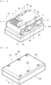
- FIG. 1 is a perspective view of a modular battery pack according to the present invention
- FIG. 2 is a perspective view of a modular battery pack according to a first embodiment with a case of a base pack removed
- FIG. 3 is a perspective view of an add-on pack in the modular battery pack according to the first embodiment.
- the add-on pack of FIG. 3 may also be utilized as an add-on pack of a modular battery pack according to a second embodiment, a description of which will follow.
- the modular battery pack includes a base pack 100 equipped with a battery pack connector 110 configured to function as a terminal of the battery pack and an add-on pack 200 coupled to the base pack 100 in order to increase the capacity of the battery pack.
- the battery pack connector 110 is disposed on a first surface 101 of the base pack 100, which is an upper surface, the battery pack connector 110 is electrically connected to a coupling terminal of the base pack 100 in a pack case 210, and the base pack 100 and the add-on pack 200 are electrically connected to each other in parallel, whereby the battery pack connector 110 functions as a terminal of the entirety of the battery pack. That is, the battery pack connector 110 may function as at least one of an external input/output terminal, a power terminal, and a communication terminal.
- cylindrical battery cells 10 are arranged in tight contact with each other, and adjacent cylindrical battery cells 10 are alternately arranged such that a direction in which a cap assembly 11 faces and a direction in which a can bottom 12 faces are opposite each other.
- a BMS may be disposed on an upper surface of the cylindrical battery cell 10, and the BMS may be connected to the battery pack connector 110.
- a coupling terminal of the base pack 100 may be exposed at a position corresponding to a through-hole 201 and a coupling terminal 230 formed at the first surface 101 of the add-on pack 200 shown in FIG. 3 , and may be in contact with the coupling terminal 230 in an overlapping fashion in an upward-downward direction.
- the coupling terminal protruding from the second surface of the pack case 210 of the base pack 100 is configured to be in contact with the coupling terminal 230 of the add-on pack 200 located under the base pack 100 between the same polarities, whereby the base pack 100 and the add-on pack 200 are connected to each other in parallel.
- the busbar 301 may protrude outward from the pack case 210 through the through-hole 201 of the pack case 210 so as to function as a coupling terminal.
- a separate coupling terminal 230 may be coupled to the other end 302 of the busbar 301, which is bent, and the coupling terminal 230 may be disposed so as to extend through the through-hole 201 of the pack case 210.
- the other end 302 of the busbar which is bent to the first surface of the pack case 210, may be bent upward, as shown in FIG. 2 , or may not be bent upward so as to come into face-to-face contact with a lower surface of the BMS.
- the through-hole 201 may be formed in the pack case 210 adjacent to the other end 302 of the busbar 301, which is bent, and the busbar 301 is disposed between two cylindrical battery cells 10, wherein the position of the through-hole corresponding to the other end 302 of the busbar coupled to the end of a first side A of the cylindrical battery cell and the position of the through-hole corresponding to the other end 302 of the busbar coupled to the end of a second side B of the cylindrical battery cell are disposed so as to mismatch in direction X of FIG. 3 .
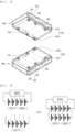
- FIG. 4 is an exploded perspective view of a modular battery pack according to a second embodiment
- FIG. 5 is an exploded perspective view showing coupling terminals of the base pack and the add-on pack according to the first embodiment.
- the modular battery pack according to the second embodiment is configured to have a structure in which an add-on pack 200 is further added to the lowermost end of the modular battery pack according to the first embodiment, and therefore a description of the base pack and the add-on pack of the first embodiment may be equally applied to the modular battery pack according to the second embodiment.
- the modular battery pack according to the second embodiment includes a base pack 100 having received therein two or more cylindrical battery cells 10 connected to each other in series, the base pack being formed in an overall cuboidal shape, and at least one add-on pack 200 having received therein two or more cylindrical battery cells 10 connected to each other in series, the add-on pack being formed in an overall cuboidal shape.
- FIG. 4 shows two add-on packs 200.
- the cylindrical battery cells 10 are disposed side by side in parallel in each of the base pack 100 and the add-on pack 200, and cylindrical side surfaces of the cylindrical battery cells 10 face a first surface 101 and a second surface 102 of each of the base pack 100 and the add-on pack 200.
- each of the base pack 100 and the add-on pack 200 is disposed such that the side surfaces of the cylindrical battery cells 10 face each other.
- the number of the cylindrical battery cells 10 received in the base pack 100 may be equal to the number of the cylindrical battery cells 10 received in the add-on pack 200, and therefore the base pack 100 and the add-on pack 200 may have the same area in a stacking direction.
- the cylindrical battery cells 10 are disposed in parallel in each of the base pack 100 and the add-on pack 200, and adjacent cylindrical battery cells 10 are disposed such that a cap assembly 11 and a can bottom 12 face in opposite directions. That is, when viewed in direction A, the adjacent cylindrical battery cells 10 are disposed such that the cap assembly 11 and the can bottom 12 are alternately repeated.
- the cylindrical battery cells 10 are connected to each other in series, wherein the cylindrical battery cells 10 are connected to each other in series via a busbar 301 in each of the base pack 100 and the add-on pack 200.
- the busbar 301 which is configured to allow the cylindrical battery cells 10 to be connected to each other in series therethrough, may be coupled so as to connect the cap assembly 11 and the can bottom 12 of neighboring cylindrical battery cells to each other, whereby electrical connection may be formed.
- the cylindrical battery cells 10 are connected to each other in series in a pack case of each of the base pack 100 and the add-on pack 200, and only the busbar 301 for electrical connection to the outside or coupling terminals 130 and 230 coupled to the busbar 301 protrude outward.
- the number of the add-on pack packs coupled to the base pack may be set in consideration of the capacity and usage time of an energy source required by a device in which the battery pack is used, and the base pack 100 and the add-on pack packs 200 may be connected to each other in parallel to increase the overall capacity of the battery pack.
- the number of cylindrical battery cells to be connected to each other in series may be determined by first setting desired voltage.
- both the base pack and the add-on pack have i) only series-connection configurations therein and ii) the same number of cylindrical battery cells.
- a battery pack connector 110 configured to function as a terminal of the entirety of the battery pack and a BMS 120 configured to manage the battery pack may be added to the base pack 100.
- Each of the base pack 100 and the add-on pack 200 includes a first surface 101 and a second surface 102 that face side surfaces of the cylindrical battery cells 10 therein.
- the first surface 101 refers to an upper surface of each of the base pack 100 and the add-on pack 200
- the second surface 102 refers to a lower surface of each of the base pack 100 and the add-on pack 200.
- the battery pack connector 110 and the BMS 120 are disposed at the first surface 101 of the base pack 100, and the first surface 101 of the add-on pack 200 is disposed so as to face the second surface 102 of the base pack 100.
- the two or more add-on packs 200 When two or more add-on packs 200 are connected, the two or more add-on packs are stacked such that a first surface 101 of a new add-on pack 200 faces the second surface 102 of the already disposed add-on pack 200.
- coupling terminals 130 and 230 for electrical parallel connection are disposed at the second surface 102 of the base pack 100 and the first surface 101 and second surface 102 of the add-on pack 200.
- the coupling terminals 230 may include two distal terminals 232 located at the outermost ends of series connection and four intermediate terminals 231 excluding the distal terminals.
- the stacked add-on packs 200 are disposed such that the coupling terminals 230 protruding outward from the pack case are in tight contact with each other or in contact with each other in the upward-downward direction, wherein the distal terminal 232 protruding from the second surface of the add-on pack 200 located above may contact the distal terminals 232 protruding from the first surface of the add-on pack 200 located below, and the intermediate terminal 231 protruding from the second surface of the add-on pack 200 located above may contact the intermediate terminal protruding from the first surface of the add-on pack 200 located below, whereby electrical connection may be formed. Consequently, parallel connection may be formed between the two distal terminals 232.
- the two distal terminals 232 and the four intermediate terminals 231 must be disposed on the first surface 101 and the second surface 102 in the same shape at the same positions in order to form continuous parallel connection in the state in which a plurality of add-on packs is stacked.
- a separate terminal may be added to each of the first surface 101 and the second surface 102 in order to measure the voltage of each of the cylindrical battery cells 10 in each of the base pack 100 and the add-on pack 200.
- the terminal is not intended to supply power and is for voltage measurement purposes only, and may be different in width or thickness from the two distal terminals 232 and the four intermediate terminals 231.
- a terminal configured to transmit the voltage measurement result to the BMS 120 of the base pack 100 may be provided separately from the coupling terminals 130 and 230.
- the battery cells 10 in the add-on packs 200 may be connected to the BMS 120 of the base pack 100 via the coupling terminals 130 and 230, whereby the BMS of the base pack may measure the voltage of the base pack and the add-on pack connected thereto.
- the add-on pack 200 includes a first add-on pack directly connected to the base pack 100, and a second add-on pack coupled to the first add-on pack under the first add-on pack
- a coupling terminal 230 for electrical connection with the base pack 100 is located at a first surface 101 of the first add-on pack
- a coupling terminal 230 for electrical connection with the second add-on pack is located at a second surface of the first add-on pack.
- the coupling terminal 130 located at the second surface 102 of the base pack 100 and the coupling terminal 230 located at the first surface of the first add-on pack are in physical contact with each other to form electrical parallel connection.
- the BMS 120 located at the first surface 101 of the base pack 100 may be electrical connected to all of the cylindrical battery cells 10 in the base pack 100, whereby an electrical connection structure between the cylindrical battery cells 10 and the BMS 120 and the battery pack connector 110 may be formed at the first surface 101 of the base pack 100.
- Coupling terminals 230 for electrical connection with the first add-on pack located thereabove and another add-on pack located thereunder are located at the first surface and the second surface of the second add-on pack, wherein the coupling terminal 230 located at the second surface of the first add-on pack and the coupling terminal 230 located at the first surface of the second add-on pack may be in physical contact with each other to form electrical parallel connection.
- a coupling terminal 130 including two distal terminals 132 and four intermediate terminals 131 is located at the second surface 102 of the base pack 100, which is a lower surface
- a coupling terminal 230 including two distal terminals 232 and four intermediate terminals 231 is located at the first surface 101 of the add-on pack 200, which is an upper surface.
- the distal terminals 132 of the base pack 100 come into tight contact with the distal terminals 232 of the add-on pack 200, and the intermediate terminals 131 of the base pack 100 come into tight contact with the intermediate terminals 231 of the add-on pack.
- the coupling terminal 130 of the base pack 100 and the coupling terminal 230 of the add-on pack 200 may protrude outward.
- the distal terminal 132 may have at least one of a leaf spring shape, a ring spring shape, and a blade-clip shape
- the distal terminal 232 may have a plate-shaped structure.
- the relationship between the intermediate terminal 131 and the intermediate terminal 231 may be identical to the relationship between the distal terminal 132 and the distal terminal 232.
- the coupling terminal 130 located at the second surface 102 of the base pack 100 of FIG. 5 may be identical in shape to the coupling terminal 230 located at the second surface 102 of the add-on pack 200.
- the coupling terminals 230 of the add-on packs 200 may be arranged so as to be in contact with each other to form electrical connection.
- a detachable member configured to further physically couple the base pack 100 and the add-on pack 200 to each other may be disposed at the second surface 102 of the base pack 100 and the first surface 101 and the second surface 102 of the add-on pack 200.
- a spring configured to allow the base pack 100 and the add-on pack 200 to be coupled to or separated from each other therethrough
- a configuration in which the spring is compressively deformed to couple the base pack 100 and the add-on pack 200 to each other and is decompressed to separate the base pack 100 and the add-on pack 200 from each other may be used.
- a lever structure or a fixing hook may be as the detachable member such that the base pack 100 and the add-on pack 200 cannot be easily separated from each other.
- the detachable member is preferably disposed at the first surface 101 and the second surface 102, and may be disposed separately at side surfaces of the base pack 100 and the add-on pack 200.
- the base pack and the add-on pack may be coupled to each other as a whole and may then be separately fixed such that the exteriors of the base pack and the add-on pack are entirely wrapped.
- a battery pack (1S Pack) including a single cylindrical battery cell requires two terminals V- and V+.
- FIG. 6 is a circuit diagram of the modular battery pack according to the first embodiment.
- 5S1P means that five battery cells are connected to each other in series to constitute one parallel connection unit.
- V- a battery pack
- V1, V2, V3, V4, and V+ V5
- 5S1P connection above may be configured for a base pack, and all battery cells are connected to a BMS in parallel.
- 5S1P connection below may be configured for an add-on pack, and all battery cells are connected to a series circuit in parallel. Consequently, in a circuit diagram, in which the base pack and the add-on pack are coupled to each other, located at the right side, all of the battery cells are substantially connected to each other in parallel and in series.
- the resistance of the base pack and the add-on pack may be measured even though a single BMS is applied, and a battery pack with lower resistance may be manufactured.
- FIG. 7 is a see-through sectional view in direction A of FIG. 4 .
- a base pack 100 and two add-on packs 200 are stacked and configured to have the same horizontal planar sizes.
- the base pack 100 and the add-on packs 200 are stacked in an overlapping state such that outer peripheries thereof coincide with each other in a stacking direction.
- a coupling terminal 130 is located at a second surface 1023 of the base pack 100, and coupling terminals 230 are located at a first surface and a second surface of each of the add-on packs 200 so as to coincide in position with the coupling terminal 130.
- the coupling terminal 130 of the base pack 100 and the coupling terminal 230 of the add-on pack 200 are disposed in tight contact with each other and are physically and electrically connected to each other, and the coupling terminals 230 of the add-on packs are disposed in tight contact with each other and are physically and electrically connected to each other.
- FIG. 8 is a perspective view of a modular battery pack according to a third embodiment with a case of a base pack removed
- FIG. 9 is a perspective view of an add-on pack in the modular battery pack according to the third embodiment.
- the modular battery pack according to the third embodiment is identical to the modular battery packs according to the first and second embodiments in that the base pack disposed on the add-on pack 200 is configured such that five cylindrical battery cells 10 received therein are connected to each other in series via a busbar 301, but the modular battery pack according to the third embodiment is different from the modular battery packs according to the first and second embodiments in that only the other ends 302 of opposite end busbars 301 constituting series connection of the cylindrical battery cells 10 are bent upward.
- two through-holes 201 are formed in a first surface 101 of a pack case 210, and a coupling terminal 230 protrudes through each through-hole 201, which is in the form of having only distal terminals without intermediate terminals.
- the configuration of the through-holes 201 and the coupling terminals 230 formed at the first surface of the add-on pack 200 shown in FIG. 9 may be equally applied to through-holes 201 and coupling terminals 230 formed at a second surface of the base pack of the modular battery pack according to the third embodiment.
- FIG. 10 is an exploded see-through perspective view of a modular battery pack according to a fourth embodiment, wherein the add-on pack 200 shown in FIG. 9 may constitute an add-on pack of the modular battery pack according to the fourth embodiment shown in FIG. 10 .
- FIG. 11 is an exploded see-through perspective view showing coupling terminals of the base pack and the add-on pack according to the fourth embodiment
- FIG. 12 is a circuit diagram of the modular battery pack according to the fourth embodiment.
- the modular battery pack according to the fourth embodiment is configured to have a structure in which an add-on pack 200 is further added to the lowermost end of the modular battery pack according to the third embodiment, and therefore a description of the base pack and the add-on pack of the third embodiment may be equally applied to the modular battery pack according to the fourth embodiment.
- each of the modular battery packs according to the third and fourth embodiments is configured such that the coupling terminal 230 exposed out of the pack case is constituted by two distal terminals 232, the battery cells disposed in the base pack 100 are not connected to the battery cells disposed in the add-on pack 200 in parallel, and the battery cells disposed in the add-on pack 200 are not connected to the battery cells disposed in the other add-on pack 200 in parallel.
- one of the distal terminals of the base pack 100 which is a positive electrode
- one of the distal terminals of the add-on pack 200 which is a positive electrode
- the other of the distal terminals of the base pack 100 which is a negative electrode
- the positive electrode and the negative electrode constituting the distal terminals of the add-on pack 200 are coupled to a positive electrode and a negative electrode constituting distal terminals of the other add-on pack 200, respectively, whereby parallel connection is formed between the base pack and the add-on pack and between the add-on packs.
- 5S1P connection above may be configured for a base pack, and all battery cells are connected to a BMS in parallel.
- 5S1P connection below may be configured for an add-on pack, and all battery cells constitute a series circuit. Consequently, in a circuit diagram, in which the base pack and the add-on pack are coupled to each other, located at the right side, the base pack and the add-on pack are connected to each other in parallel, and all of the battery cells in the base pack are connected to the BMS in parallel, whereby the BMS may measure the voltage of each of the battery cells in the add-on pack.
- the BMS may be configured to be coupled to only opposite ends of the battery cells constituting the base pack.
- modular battery packs according to the first and second embodiments may be equally applied to the modular battery packs according to the third and fourth embodiments.
- FIG. 13 is a see-through sectional view in direction A of FIG. 10 .
- the BMS 120 is located at an upper part of the base pack 100, wherein the other end 302 of the busbar connected to the cylindrical battery cells 10 in the base pack 100 is disposed so as to extend through the BMS 120 and is coupled to the BMS 120.
- the battery pack according to the present invention includes one base pack and one or more add-on packs, and is configured to have a structure in which add-on packs can be theoretically continuously coupled to each other without limit to number, whereby it is possible to provide a large-capacity battery pack in a simple and easy way in consideration of required capacity and usage time of a power tool.
Landscapes
- Chemical & Material Sciences (AREA)
- Chemical Kinetics & Catalysis (AREA)
- Electrochemistry (AREA)
- General Chemical & Material Sciences (AREA)
- Engineering & Computer Science (AREA)
- Microelectronics & Electronic Packaging (AREA)
- Manufacturing & Machinery (AREA)
- Life Sciences & Earth Sciences (AREA)
- Biophysics (AREA)
- Computer Hardware Design (AREA)
- Battery Mounting, Suspending (AREA)
- Connection Of Batteries Or Terminals (AREA)
Abstract
Description
- This application claims the benefit of priority to
Korean Patent Application No. 2022-0182120 filed on December 22, 2022 - The present invention relates to a modular battery pack. More particularly, the present invention relates to a modular battery pack that can be assembled and used in different sizes and capacities without the need to manufacture new dies and molds.
- A battery pack including a lithium secondary battery is used as a power tool in a variety of applications, and the number of battery cells constituting the battery pack may be changed depending on the required capacity and output. Depending on the number of battery cells, a housing configured to receive the battery cells may be changed, making it substantially difficult to change the number of battery cells as initially designed.
- Patent Document 1 relates to a battery device for vehicles including a basic battery pack that is basically mounted in a vehicle and an auxiliary battery pack that may be optionally mounted in the vehicle, wherein each of the basic battery pack and the auxiliary battery pack includes a plurality of battery cells, the plurality of battery cells being connected to each other in series and/or parallel.
- The auxiliary battery pack may be further connected to the basic battery pack in order to increase electrical energy of the vehicle. In addition, the auxiliary battery pack may be connected to the basic battery pack in series via at least one junction box, which makes it easy and reliable to further mount the auxiliary battery pack to the basic battery pack.
- Patent Document 1 discloses a configuration and method for connecting and using a single auxiliary battery pack to a basic battery pack, but does not disclose technology for further coupling and using additional auxiliary battery packs.
- Patent Document 2 relates to a battery including two or more battery modules, wherein each of the battery modules includes a plurality of battery cells electrically connected to each other in series and/or parallel, a positive electrode tab and a first module connection member are connected to each other in an electrically conductive manner, a negative electrode tab and a second module connection member are connected to each other in an electrically conductive manner, a module connection member of the first battery module and a module connection member of the second battery module are connected to each other in an electrically conductive manner, and the module connection members are electrically conductively connected to each other through plug connection.
- Patent Document 2 discloses a configuration in which a first module connection member of the first battery module and a first module connection member of the second battery module are connected to each other in an electrically conductive manner, or a second module connection member of the first battery module and a second module connection member of the second battery module are connected to each other in an electrically conductive manner, but does not disclose a configuration in which three or more battery modules are connected to each other.
- Conventionally, as described above, methods of increasing additional capacity only to a limited extent were proposed. Technology capable of providing battery packs of various sizes and capacities in an easy, simple, and economical manner has not yet been proposed.
-
- (Patent Document 1)
Korean Patent Application Publication No. 2017-0053071 (2017.05.15 - (Patent Document 2)
Korean Patent Application Publication No. 2018-0124090 (2018.11.20 - The present invention has been made in view of the above problems, and it is an object of the present invention to provide a new modular battery pack capable of easily increasing or decreasing the capacity of the battery pack and reducing manufacturing costs of dies and molds while reducing the number of parts.
- In order to accomplish the above object, the present invention provides a modular battery pack including a base pack having received therein two or more cylindrical battery cells connected to each other in series, the base pack configured in a cuboidal shape overall, and at least one add-on pack having received therein two or more cylindrical battery cells connected to each other in series, the add-on pack configured in a cuboidal shape overall, wherein the two or more cylindrical battery cells are disposed side by side in parallel in each of the base pack and the add-on pack, the base pack and the add-on pack are disposed such that side surfaces of the two or more cylindrical battery cells face each other, and the base pack and the add-on pack are connected to each other in parallel.
- The base pack may include a battery pack connector configured to function as a terminal of an entirety of the modular battery pack and a BMS configured to manage the entirety of the modular battery pack.
- Each of the base pack and the add-on pack may include a first surface and a second surface configured to face the side surfaces of the two or more cylindrical battery cells therein, the battery pack connector and the BMS may be disposed at the first surface of the base pack while the first surface of the add-on pack may be disposed so as to face the second surface of the base pack, and when two or more add-on packs are connected, the two or more add-on packs may be stacked such that a first surface of an additional add-on pack faces the second surface of the add-on pack which is already disposed.
- Coupling terminals for electrical parallel connection of the base pack and the add-on pack may be disposed at the second surface of the base pack, and at the first surface and the second surface of the add-on pack.
- Fixing portions for physical coupling of the base pack and the add-on pack may be disposed at the second surface of the base pack, and at the first surface and second surface of the add-on pack.
- The base pack and the add-on pack may be physically coupled to each other via the coupling terminals.
- Each of the coupling terminals may have at least one of a plate-shaped structure, a leaf spring shape, a ring spring shape, and a blade-clip shape.
- The two or more cylindrical battery cells may be disposed in parallel in each of the base pack and the add-on pack, and adjacent cylindrical battery cells of the two or more cylindrical battery cells may be disposed such that cap assemblies thereof face in opposite directions.
- A number of the two or more cylindrical battery cells received in the base pack and the number of the two or more cylindrical battery cells received in the add-on pack may be equal to each other.
- The two or more cylindrical battery cells received in each of the base pack and the add-on pack may be connected to each other in series via a busbar.
- One end of the busbar coupled to electrode terminals of the two or more cylindrical battery cells may be bent so as to extend through a pack case of each of the base pack and the add-on pack.
- A plurality of add-on packs may be coupled to the second surface of the base pack in a parallel connection, and the plurality of add-on packs may be coupled to each other in a parallel connection.
- In addition, the present invention may provide various combinations of the above solving means.
- As is apparent from the above description, a modular battery pack according to the present invention is configured such that a plurality of add-on packs can be coupled to a single base pack, whereby it is possible to provide a battery pack having a desired capacity through simple assembly.
- Since one base pack and add-on packs having a certain shape are provided, it is possible to reduce the number of parts and reduce manufacturing costs of dies and molds.
- The base pack and the add-on pack are connected to each other in parallel, and the add-on packs are connected to each other in parallel, whereby separation therebetween may be easily achieved even during use.
-
-
FIG. 1 is a perspective view of a modular battery pack according to the present invention. -
FIG. 2 is a perspective view of a modular battery pack according to a first embodiment with a case of a base pack removed. -
FIG. 3 is a perspective view of an add-on pack in the modular battery pack according to the first embodiment. -
FIG. 4 is an exploded perspective view of a modular battery pack according to a second embodiment. -
FIG. 5 is an exploded perspective view showing coupling terminals of the base pack and the add-on pack according to the first embodiment. -
FIG. 6 is a circuit diagram of the modular battery pack according to the first embodiment. -
FIG. 7 is a see-through sectional view in direction A ofFIG. 4 . -
FIG. 8 is a perspective view of a modular battery pack according to a third embodiment with a case of a base pack removed. -
FIG. 9 is a perspective view of an add-on pack in the modular battery pack according to the third embodiment. -
FIG. 10 is an exploded see-through perspective view of a modular battery pack according to a fourth embodiment. -
FIG. 11 is an exploded see-through perspective view showing coupling terminals of the base pack and the add-on pack according to the fourth embodiment. -
FIG. 12 is a circuit diagram of the modular battery pack according to the fourth embodiment. -
FIG. 13 is a see-through sectional view in direction A ofFIG. 10 . - Now, preferred embodiments of the present invention will be described in detail with reference to the accompanying drawings such that the preferred embodiments of the present invention can be easily implemented by a person having ordinary skill in the art to which the present invention pertains. In describing the principle of operation of the preferred embodiments of the present invention in detail, however, a detailed description of known functions and configurations incorporated herein will be omitted when the same may obscure the subject matter of the present invention.
- In addition, the same reference numbers will be used throughout the drawings to refer to parts that perform similar functions or operations. In the case in which one part is said to be connected to another part throughout the specification, not only may the one part be directly connected to the other part, but also, the one part may be indirectly connected to the other part via a further part. In addition, that a certain element is included does not mean that other elements are excluded, but means that such elements may be further included unless mentioned otherwise.
- In addition, a description to embody elements through limitation or addition may be applied to all inventions, unless particularly restricted, and does not limit a specific invention.
- Also, in the description of the invention and the claims of the present application, singular forms are intended to include plural forms unless mentioned otherwise.
- Also, in the description of the invention and the claims of the present application, "or" includes "and" unless mentioned otherwise. Therefore, "including A or B" means three cases, namely, the case including A, the case including B, and the case including A and B.
- Embodiments of the present invention will be described in detail with reference to the drawings.
-
FIG. 1 is a perspective view of a modular battery pack according to the present invention,FIG. 2 is a perspective view of a modular battery pack according to a first embodiment with a case of a base pack removed, andFIG. 3 is a perspective view of an add-on pack in the modular battery pack according to the first embodiment. The add-on pack ofFIG. 3 may also be utilized as an add-on pack of a modular battery pack according to a second embodiment, a description of which will follow. - Referring to
FIGS. 1 to 3 , the modular battery pack according to the present invention includes abase pack 100 equipped with abattery pack connector 110 configured to function as a terminal of the battery pack and an add-onpack 200 coupled to thebase pack 100 in order to increase the capacity of the battery pack. - The
battery pack connector 110 is disposed on afirst surface 101 of thebase pack 100, which is an upper surface, thebattery pack connector 110 is electrically connected to a coupling terminal of thebase pack 100 in apack case 210, and thebase pack 100 and the add-onpack 200 are electrically connected to each other in parallel, whereby thebattery pack connector 110 functions as a terminal of the entirety of the battery pack. That is, thebattery pack connector 110 may function as at least one of an external input/output terminal, a power terminal, and a communication terminal. - In each of the
base pack 100 and the add-onpack 200,cylindrical battery cells 10 are arranged in tight contact with each other, and adjacentcylindrical battery cells 10 are alternately arranged such that a direction in which acap assembly 11 faces and a direction in which a can bottom 12 faces are opposite each other. - A
busbar 301 is coupled to electrode terminals of thecylindrical battery cells 10, and a plurality ofcylindrical battery cells 10 is connected to each other in series via thebusbar 301. - The
other end 302 of thebusbar 301 coupled to the electrode terminals of thecylindrical battery cells 10 is bent so as to extend through thepack case 210 of the add-onpack 200, as shown inFIG. 3 , and the add-onpack 200 has a through-hole 201 formed in an upper surface of thepack case 210, whereby theother end 302 of thebusbar 301, which is bent, may protrude out of thepack case 210 through the through-hole 201. - In the case of the
base pack 100, a BMS may be disposed on an upper surface of thecylindrical battery cell 10, and the BMS may be connected to thebattery pack connector 110. Theother end 302 of thebusbar 301 coupled to the electrode terminal of thecylindrical battery cell 10 received in the base pack, which is bent to thefirst surface 101, which is an upper surface, is connected to theBMS 120 in thepack case 210. Since no through-hole is formed in thefirst surface 101 of thepack case 210 of thebase pack 100, a configuration in which the coupling terminal is exposed through the through-hole is not included; however, at a second surface of thebase pack 100, which is an outer surface opposite thefirst surface 101, a coupling terminal of thebase pack 100 may be exposed at a position corresponding to a through-hole 201 and acoupling terminal 230 formed at thefirst surface 101 of the add-onpack 200 shown inFIG. 3 , and may be in contact with thecoupling terminal 230 in an overlapping fashion in an upward-downward direction. - Accordingly, the coupling terminal protruding from the second surface of the
pack case 210 of thebase pack 100 is configured to be in contact with thecoupling terminal 230 of the add-onpack 200 located under thebase pack 100 between the same polarities, whereby thebase pack 100 and the add-onpack 200 are connected to each other in parallel. - In the
base pack 100, theother end 302 of thebusbar 301 is connected to theBMS 120 to enable measurement of voltage or current at each terminal. In thebase pack 100, first and last parts of series connection of theother end 302 of thebusbar 301 are connected to the externalbattery pack connector 110 of the entire battery pack. - The
busbar 301 may protrude outward from thepack case 210 through the through-hole 201 of thepack case 210 so as to function as a coupling terminal. Alternatively, aseparate coupling terminal 230 may be coupled to theother end 302 of thebusbar 301, which is bent, and thecoupling terminal 230 may be disposed so as to extend through the through-hole 201 of thepack case 210. - In the
base pack 100, theother end 302 of the busbar, which is bent to the first surface of thepack case 210, may be bent upward, as shown inFIG. 2 , or may not be bent upward so as to come into face-to-face contact with a lower surface of the BMS. - The through-
hole 201 may be formed in thepack case 210 adjacent to theother end 302 of thebusbar 301, which is bent, and thebusbar 301 is disposed between twocylindrical battery cells 10, wherein the position of the through-hole corresponding to theother end 302 of the busbar coupled to the end of a first side A of the cylindrical battery cell and the position of the through-hole corresponding to theother end 302 of the busbar coupled to the end of a second side B of the cylindrical battery cell are disposed so as to mismatch in direction X ofFIG. 3 . -
FIG. 4 is an exploded perspective view of a modular battery pack according to a second embodiment, andFIG. 5 is an exploded perspective view showing coupling terminals of the base pack and the add-on pack according to the first embodiment. - Referring to
FIG. 4 , the modular battery pack according to the second embodiment is configured to have a structure in which an add-onpack 200 is further added to the lowermost end of the modular battery pack according to the first embodiment, and therefore a description of the base pack and the add-on pack of the first embodiment may be equally applied to the modular battery pack according to the second embodiment. - The modular battery pack according to the second embodiment includes a
base pack 100 having received therein two or morecylindrical battery cells 10 connected to each other in series, the base pack being formed in an overall cuboidal shape, and at least one add-onpack 200 having received therein two or morecylindrical battery cells 10 connected to each other in series, the add-on pack being formed in an overall cuboidal shape.FIG. 4 shows two add-on packs 200. - The
cylindrical battery cells 10 are disposed side by side in parallel in each of thebase pack 100 and the add-onpack 200, and cylindrical side surfaces of thecylindrical battery cells 10 face afirst surface 101 and asecond surface 102 of each of thebase pack 100 and the add-onpack 200. In addition, each of thebase pack 100 and the add-onpack 200 is disposed such that the side surfaces of thecylindrical battery cells 10 face each other. - The number of the
cylindrical battery cells 10 received in thebase pack 100 may be equal to the number of thecylindrical battery cells 10 received in the add-onpack 200, and therefore thebase pack 100 and the add-onpack 200 may have the same area in a stacking direction. - The
cylindrical battery cells 10 are disposed in parallel in each of thebase pack 100 and the add-onpack 200, and adjacentcylindrical battery cells 10 are disposed such that acap assembly 11 and a can bottom 12 face in opposite directions. That is, when viewed in direction A, the adjacentcylindrical battery cells 10 are disposed such that thecap assembly 11 and thecan bottom 12 are alternately repeated. - In this state, the
cylindrical battery cells 10 are connected to each other in series, wherein thecylindrical battery cells 10 are connected to each other in series via abusbar 301 in each of thebase pack 100 and the add-onpack 200. Specifically, thebusbar 301, which is configured to allow thecylindrical battery cells 10 to be connected to each other in series therethrough, may be coupled so as to connect thecap assembly 11 and thecan bottom 12 of neighboring cylindrical battery cells to each other, whereby electrical connection may be formed. - The
cylindrical battery cells 10 are connected to each other in series in a pack case of each of thebase pack 100 and the add-onpack 200, and only thebusbar 301 for electrical connection to the outside orcoupling terminals busbar 301 protrude outward. - The number of the add-on pack packs coupled to the base pack may be set in consideration of the capacity and usage time of an energy source required by a device in which the battery pack is used, and the
base pack 100 and the add-on pack packs 200 may be connected to each other in parallel to increase the overall capacity of the battery pack. - In a basic design process, the number of cylindrical battery cells to be connected to each other in series may be determined by first setting desired voltage. In an embodiment of the present invention, both the base pack and the add-on pack have i) only series-connection configurations therein and ii) the same number of cylindrical battery cells.
- i) In the case of the base pack, the cylindrical battery cells connected to each other in series therein may be connected to each other in parallel again. When applied to
FIG. 4 , abase pack 100 including five cylindrical battery cells and two add-onpacks 200 each including five cylindrical battery cells may be stacked to manufacture a three-layered battery pack. - ii) Although
FIG. 4 shows that each of the base pack and the add-on pack includes five cylindrical battery cells, the number of cylindrical battery cells may be increased to constitute a large-capacity base pack or a large-capacity add-on pack, as needed. In this case, it is preferable for the cylindrical battery cells to be connected to each other in series in each of the base pack and the add-on pack and to be connected to each other in parallel between the base pack and the add-on pack. When applied toFIG. 4 , the cylindrical battery cells may be increased in multiples of 5, such as 5, 10, 15, 20, and 25, by increasing the number of add-on packs coupled to the base pack. - In order to charge and discharge the entire battery pack, a
battery pack connector 110 configured to function as a terminal of the entirety of the battery pack and aBMS 120 configured to manage the battery pack may be added to thebase pack 100. - Each of the
base pack 100 and the add-onpack 200 includes afirst surface 101 and asecond surface 102 that face side surfaces of thecylindrical battery cells 10 therein. Throughout this specification, thefirst surface 101 refers to an upper surface of each of thebase pack 100 and the add-onpack 200, and thesecond surface 102 refers to a lower surface of each of thebase pack 100 and the add-onpack 200. - The
battery pack connector 110 and theBMS 120 are disposed at thefirst surface 101 of thebase pack 100, and thefirst surface 101 of the add-onpack 200 is disposed so as to face thesecond surface 102 of thebase pack 100. - When two or more add-on
packs 200 are connected, the two or more add-on packs are stacked such that afirst surface 101 of a new add-onpack 200 faces thesecond surface 102 of the already disposed add-onpack 200. - In this case,
coupling terminals second surface 102 of thebase pack 100 and thefirst surface 101 andsecond surface 102 of the add-onpack 200. - Referring back to
FIG. 4 , the five cylindrical battery cells are received in the add-onpack 200, and sixcoupling terminals 230 are disposed at thefirst surface 101 of the add-on pack. Thecoupling terminals 230 may include twodistal terminals 232 located at the outermost ends of series connection and fourintermediate terminals 231 excluding the distal terminals. - The stacked add-on
packs 200 are disposed such that thecoupling terminals 230 protruding outward from the pack case are in tight contact with each other or in contact with each other in the upward-downward direction, wherein thedistal terminal 232 protruding from the second surface of the add-onpack 200 located above may contact thedistal terminals 232 protruding from the first surface of the add-onpack 200 located below, and theintermediate terminal 231 protruding from the second surface of the add-onpack 200 located above may contact the intermediate terminal protruding from the first surface of the add-onpack 200 located below, whereby electrical connection may be formed. Consequently, parallel connection may be formed between the twodistal terminals 232. - In the case of
FIG. 4 , since the twodistal terminals 232 and the fourintermediate terminals 231 are connected to thebusbar 301 coupled to the electrode terminals of thecylindrical battery cells 10, all of thecylindrical battery cells 10 are electrically connected to each other via thedistal terminals 232 and theintermediate terminals 231. - The two
distal terminals 232 and the fourintermediate terminals 231 must be disposed on thefirst surface 101 and thesecond surface 102 in the same shape at the same positions in order to form continuous parallel connection in the state in which a plurality of add-on packs is stacked. - Although not shown in
FIG. 4 , a separate terminal may be added to each of thefirst surface 101 and thesecond surface 102 in order to measure the voltage of each of thecylindrical battery cells 10 in each of thebase pack 100 and the add-onpack 200. The terminal is not intended to supply power and is for voltage measurement purposes only, and may be different in width or thickness from the twodistal terminals 232 and the fourintermediate terminals 231. In addition, although not shown in the figure, a terminal configured to transmit the voltage measurement result to theBMS 120 of thebase pack 100 may be provided separately from thecoupling terminals packs 200, thebattery cells 10 in the add-onpacks 200 may be connected to theBMS 120 of thebase pack 100 via thecoupling terminals - When the add-on
pack 200 includes a first add-on pack directly connected to thebase pack 100, and a second add-on pack coupled to the first add-on pack under the first add-on pack, acoupling terminal 230 for electrical connection with thebase pack 100 is located at afirst surface 101 of the first add-on pack, and acoupling terminal 230 for electrical connection with the second add-on pack is located at a second surface of the first add-on pack. Thecoupling terminal 130 located at thesecond surface 102 of thebase pack 100 and thecoupling terminal 230 located at the first surface of the first add-on pack are in physical contact with each other to form electrical parallel connection. TheBMS 120 located at thefirst surface 101 of thebase pack 100 may be electrical connected to all of thecylindrical battery cells 10 in thebase pack 100, whereby an electrical connection structure between thecylindrical battery cells 10 and theBMS 120 and thebattery pack connector 110 may be formed at thefirst surface 101 of thebase pack 100. - Coupling
terminals 230 for electrical connection with the first add-on pack located thereabove and another add-on pack located thereunder are located at the first surface and the second surface of the second add-on pack, wherein thecoupling terminal 230 located at the second surface of the first add-on pack and thecoupling terminal 230 located at the first surface of the second add-on pack may be in physical contact with each other to form electrical parallel connection. - Referring to
FIG. 5 , acoupling terminal 130 including twodistal terminals 132 and fourintermediate terminals 131 is located at thesecond surface 102 of thebase pack 100, which is a lower surface, and acoupling terminal 230 including twodistal terminals 232 and fourintermediate terminals 231 is located at thefirst surface 101 of the add-onpack 200, which is an upper surface. - When the
base pack 100 and the add-onpack 200 are stacked so as to overlap each other, thedistal terminals 132 of thebase pack 100 come into tight contact with thedistal terminals 232 of the add-onpack 200, and theintermediate terminals 131 of thebase pack 100 come into tight contact with theintermediate terminals 231 of the add-on pack. - The
coupling terminal 130 of thebase pack 100 and thecoupling terminal 230 of the add-onpack 200 may protrude outward. When thedistal terminal 132 has a plate-shaped structure, thedistal terminal 232 may have at least one of a leaf spring shape, a ring spring shape, and a blade-clip shape, and when thedistal terminal 132 has at least one of a leaf spring shape, a ring spring shape, and a blade-clip shape, thedistal terminal 232 may have a plate-shaped structure. - The relationship between the
intermediate terminal 131 and theintermediate terminal 231 may be identical to the relationship between thedistal terminal 132 and thedistal terminal 232. - The
coupling terminal 130 located at thesecond surface 102 of thebase pack 100 ofFIG. 5 may be identical in shape to thecoupling terminal 230 located at thesecond surface 102 of the add-onpack 200. Thus, even on a stacking plane where two add-onpacks 200 are stacked, thecoupling terminals 230 of the add-onpacks 200 may be arranged so as to be in contact with each other to form electrical connection. - Physical coupling between the
base pack 100 and the add-onpack 200 and physical coupling between the add-onpacks 200 may be formed only by coupling between thecoupling terminals - Although not shown in
FIG. 5 , a detachable member configured to further physically couple thebase pack 100 and the add-onpack 200 to each other may be disposed at thesecond surface 102 of thebase pack 100 and thefirst surface 101 and thesecond surface 102 of the add-onpack 200. - For example, when a spring is used as the detachable member configured to allow the
base pack 100 and the add-onpack 200 to be coupled to or separated from each other therethrough, a configuration in which the spring is compressively deformed to couple thebase pack 100 and the add-onpack 200 to each other and is decompressed to separate thebase pack 100 and the add-onpack 200 from each other may be used. Alternatively, a lever structure or a fixing hook may be as the detachable member such that thebase pack 100 and the add-onpack 200 cannot be easily separated from each other. - The detachable member is preferably disposed at the
first surface 101 and thesecond surface 102, and may be disposed separately at side surfaces of thebase pack 100 and the add-onpack 200. In addition, the base pack and the add-on pack may be coupled to each other as a whole and may then be separately fixed such that the exteriors of the base pack and the add-on pack are entirely wrapped. - In a specific example, when cylindrical battery cells are disposed in series, on the assumption that the terminals located at opposite ends thereof are represented by V- and V+, a battery pack (1S Pack) including a single cylindrical battery cell requires two terminals V- and V+.
-
FIG. 6 is a circuit diagram of the modular battery pack according to the first embodiment. - In another embodiment, referring to
FIG. 6 , 5S1P means that five battery cells are connected to each other in series to constitute one parallel connection unit. - For a battery pack (5S Pack) constituted by five cylindrical battery cells connected to each other in series, six terminals V- (=V0), V1, V2, V3, V4, and V+ (=V5) are required. In
FIG. 6 , 5S1P connection above may be configured for a base pack, and all battery cells are connected to a BMS in parallel. 5S1P connection below may be configured for an add-on pack, and all battery cells are connected to a series circuit in parallel. Consequently, in a circuit diagram, in which the base pack and the add-on pack are coupled to each other, located at the right side, all of the battery cells are substantially connected to each other in parallel and in series. - In this configuration, the resistance of the base pack and the add-on pack may be measured even though a single BMS is applied, and a battery pack with lower resistance may be manufactured.
-
FIG. 7 is a see-through sectional view in direction A ofFIG. 4 . - Referring to
FIG. 7 , abase pack 100 and two add-onpacks 200 are stacked and configured to have the same horizontal planar sizes. Thus, thebase pack 100 and the add-onpacks 200 are stacked in an overlapping state such that outer peripheries thereof coincide with each other in a stacking direction. - A
coupling terminal 130 is located at a second surface 1023 of thebase pack 100, andcoupling terminals 230 are located at a first surface and a second surface of each of the add-onpacks 200 so as to coincide in position with thecoupling terminal 130. Thecoupling terminal 130 of thebase pack 100 and thecoupling terminal 230 of the add-onpack 200 are disposed in tight contact with each other and are physically and electrically connected to each other, and thecoupling terminals 230 of the add-on packs are disposed in tight contact with each other and are physically and electrically connected to each other. -
FIG. 8 is a perspective view of a modular battery pack according to a third embodiment with a case of a base pack removed, andFIG. 9 is a perspective view of an add-on pack in the modular battery pack according to the third embodiment. - Referring to
FIGS. 8 and9 , when comparing the modular battery pack according to the third embodiment with the modular battery packs according to the first and second embodiments, the modular battery pack according to the third embodiment is identical to the modular battery packs according to the first and second embodiments in that the base pack disposed on the add-onpack 200 is configured such that fivecylindrical battery cells 10 received therein are connected to each other in series via abusbar 301, but the modular battery pack according to the third embodiment is different from the modular battery packs according to the first and second embodiments in that only the other ends 302 ofopposite end busbars 301 constituting series connection of thecylindrical battery cells 10 are bent upward. - Furthermore, in the add-on
pack 200 of the modular battery pack according to the third embodiment, two through-holes 201 are formed in afirst surface 101 of apack case 210, and acoupling terminal 230 protrudes through each through-hole 201, which is in the form of having only distal terminals without intermediate terminals. - The configuration of the through-
holes 201 and thecoupling terminals 230 formed at the first surface of the add-onpack 200 shown inFIG. 9 may be equally applied to through-holes 201 andcoupling terminals 230 formed at a second surface of the base pack of the modular battery pack according to the third embodiment. - In addition,
FIG. 10 is an exploded see-through perspective view of a modular battery pack according to a fourth embodiment, wherein the add-onpack 200 shown inFIG. 9 may constitute an add-on pack of the modular battery pack according to the fourth embodiment shown inFIG. 10 . -
FIG. 11 is an exploded see-through perspective view showing coupling terminals of the base pack and the add-on pack according to the fourth embodiment, andFIG. 12 is a circuit diagram of the modular battery pack according to the fourth embodiment. - Referring to
FIGS. 11 and 12 , the modular battery pack according to the fourth embodiment is configured to have a structure in which an add-onpack 200 is further added to the lowermost end of the modular battery pack according to the third embodiment, and therefore a description of the base pack and the add-on pack of the third embodiment may be equally applied to the modular battery pack according to the fourth embodiment. - Since each of the modular battery packs according to the third and fourth embodiments is configured such that the
coupling terminal 230 exposed out of the pack case is constituted by twodistal terminals 232, the battery cells disposed in thebase pack 100 are not connected to the battery cells disposed in the add-onpack 200 in parallel, and the battery cells disposed in the add-onpack 200 are not connected to the battery cells disposed in the other add-onpack 200 in parallel. - However, one of the distal terminals of the
base pack 100, which is a positive electrode, is coupled to one of the distal terminals of the add-onpack 200, which is a positive electrode, the other of the distal terminals of thebase pack 100, which is a negative electrode, is coupled to the other of the distal terminals of the add-onpack 200, which is a negative electrode, and the positive electrode and the negative electrode constituting the distal terminals of the add-onpack 200 are coupled to a positive electrode and a negative electrode constituting distal terminals of the other add-onpack 200, respectively, whereby parallel connection is formed between the base pack and the add-on pack and between the add-on packs. - Referring to
FIG. 12 , 5S1P connection above may be configured for a base pack, and all battery cells are connected to a BMS in parallel. 5S1P connection below may be configured for an add-on pack, and all battery cells constitute a series circuit. Consequently, in a circuit diagram, in which the base pack and the add-on pack are coupled to each other, located at the right side, the base pack and the add-on pack are connected to each other in parallel, and all of the battery cells in the base pack are connected to the BMS in parallel, whereby the BMS may measure the voltage of each of the battery cells in the add-on pack. - Unlike what is shown in
FIG. 12 , the BMS may be configured to be coupled to only opposite ends of the battery cells constituting the base pack. - In addition, a description of the modular battery packs according to the first and second embodiments may be equally applied to the modular battery packs according to the third and fourth embodiments.
-
FIG. 13 is a see-through sectional view in direction A ofFIG. 10 . - Referring to
FIG. 13 , theBMS 120 is located at an upper part of thebase pack 100, wherein theother end 302 of the busbar connected to thecylindrical battery cells 10 in thebase pack 100 is disposed so as to extend through theBMS 120 and is coupled to theBMS 120. - Two
coupling terminals 130 formed at thesecond surface 102 of thebase pack 100 are stacked so as to contact twocoupling terminals 230 formed at the first surface of the add-onpack 200, and the add-onpacks 200 are disposed such that thecoupling terminals 230 are in contact with each other at opposing surfaces thereof to form parallel connection, whereby electrical connection may be formed between thebase pack 100 and the one or more add-on packs 200. - As such, the battery pack according to the present invention includes one base pack and one or more add-on packs, and is configured to have a structure in which add-on packs can be theoretically continuously coupled to each other without limit to number, whereby it is possible to provide a large-capacity battery pack in a simple and easy way in consideration of required capacity and usage time of a power tool.
- Those skilled in the art to which the present invention pertains will appreciate that various applications and modifications are possible within the category of the present invention based on the above description.
-
- 10: Cylindrical battery cell
- 11: Cap assembly
- 12: Can bottom
- 100: Base pack
- 101: First surface
- 102: Second surface
- 110: Battery pack connector
- 120: BMS
- 130, 230: Coupling terminals
- 131, 231: Intermediate terminals
- 132, 232: Distal terminals
- 200: Add-on pack
- 201: Through-hole
- 210: Pack case
- 301: Busbar
- 302: Other end
- A: First side
- B: Second side
Claims (12)
- A modular battery pack comprising:a base pack having received therein two or more cylindrical battery cells connected to each other in series, the base pack configured in a cuboidal shape overall; andat least one add-on pack having received therein two or more cylindrical battery cells connected to each other in series, the add-on pack configured in a cuboidal shape overall, whereinthe two or more cylindrical battery cells are disposed side by side in parallel in each of the base pack and the add-on pack,the base pack and the add-on pack are disposed such that side surfaces of the two or more cylindrical battery cells face each other, andthe base pack and the add-on pack are connected to each other in parallel.
- The modular battery pack according to claim 1, wherein the base pack includes a battery pack connector configured to function as a terminal of an entirety of the modular battery pack and a BMS configured to manage the entirety of the modular battery pack.
- The modular battery pack according to claim 2, wherein each of the base pack and the add-on pack comprises a first surface and a second surface configured to face the side surfaces of the two or more cylindrical battery cells therein,wherein the battery pack connector and the BMS are disposed at the first surface of the base pack while the first surface of the add-on pack is disposed so as to face the second surface of the base pack, andwherein when two or more add-on packs are connected, the two or more add-on packs are stacked such that a first surface of an additional add-on pack faces the second surface of the add-on pack which is already disposed.
- The modular battery pack according to claim 3, wherein coupling terminals for electrical parallel connection of the base pack and the add-on pack are disposed at the second surface of the base pack, and at the first surface and the second surface of the add-on pack.
- The modular battery pack according to claim 3, wherein fixing portions for physical coupling of the base pack and the add-on pack are disposed at the second surface of the base pack, and at the first surface and second surface of the add-on pack.
- The modular battery pack according to claim 4, wherein the base pack and the add-on pack are physically coupled to each other via the coupling terminals.
- The modular battery pack according to claim 4, wherein each of the coupling terminals has at least one of a plate-shaped structure, a leaf spring shape, a ring spring shape, and a blade-clip shape.
- The modular battery pack according to claim 1, wherein the two or more cylindrical battery cells are disposed in parallel in each of the base pack and the add-on pack, and
wherein adjacent cylindrical battery cells of the two or more cylindrical battery cells are disposed such that cap assemblies thereof face in opposite directions. - The modular battery pack according to claim 1, wherein a number of the two or more cylindrical battery cells received in the base pack and a number of the two or more cylindrical battery cells received in the add-on pack are equal to each other.
- The modular battery pack according to claim 1, wherein the two or more cylindrical battery cells received in each of the base pack and the add-on pack are connected to each other in series via a busbar.
- The modular battery pack according to claim 10, wherein one end of the busbar coupled to electrode terminals of the two or more cylindrical battery cells is bent so as to extend through a pack case of each of the base pack and the add-on pack.
- The modular battery pack according to claim 3, wherein a plurality of add-on packs is coupled to the second surface of the base pack in a parallel connection, and
wherein the plurality of add-on packs are coupled to each other in a parallel connection.
Applications Claiming Priority (2)
| Application Number | Priority Date | Filing Date | Title |
|---|---|---|---|
| KR1020220182120A KR20240100050A (en) | 2022-12-22 | 2022-12-22 | Modular Battery Pack |
| PCT/KR2023/021017 WO2024136411A1 (en) | 2022-12-22 | 2023-12-19 | Modular battery pack |
Publications (2)
| Publication Number | Publication Date |
|---|---|
| EP4525161A1 true EP4525161A1 (en) | 2025-03-19 |
| EP4525161A4 EP4525161A4 (en) | 2025-12-10 |
Family
ID=91589493
Family Applications (1)
| Application Number | Title | Priority Date | Filing Date |
|---|---|---|---|
| EP23907694.6A Pending EP4525161A4 (en) | 2022-12-22 | 2023-12-19 | MODULAR BATTERY SET |
Country Status (6)
| Country | Link |
|---|---|
| US (1) | US20250385372A1 (en) |
| EP (1) | EP4525161A4 (en) |
| JP (1) | JP2025520214A (en) |
| KR (1) | KR20240100050A (en) |
| CN (1) | CN119452514A (en) |
| WO (1) | WO2024136411A1 (en) |
Family Cites Families (10)
| Publication number | Priority date | Publication date | Assignee | Title |
|---|---|---|---|---|
| JP4784906B2 (en) * | 2006-02-28 | 2011-10-05 | 日立工機株式会社 | Cordless power tool and battery device used therefor |
| KR101539693B1 (en) * | 2012-10-04 | 2015-07-27 | 주식회사 엘지화학 | Apparatus for waking up multi-bms |
| KR20150115250A (en) * | 2014-04-03 | 2015-10-14 | 주식회사 엘지화학 | Battery pack having inner tention-bar |
| KR20170053071A (en) | 2015-11-05 | 2017-05-15 | 현대자동차주식회사 | Vehicle battery apparatus |
| DE102016204681A1 (en) | 2016-03-22 | 2017-09-28 | Robert Bosch Gmbh | Battery and method of manufacturing a battery |
| US20200313128A1 (en) * | 2016-06-22 | 2020-10-01 | Commeo Gmbh | Accumulator module |
| US20200044212A1 (en) * | 2017-03-31 | 2020-02-06 | Tti (Macao Commercial Offshore) Limited | Scalable battery system |
| CN213816298U (en) * | 2020-12-24 | 2021-07-27 | 格力博(江苏)股份有限公司 | Battery pack systems and power tools |
| CN112356733A (en) * | 2020-10-27 | 2021-02-12 | 厦门市戴尔乐新能源汽车有限公司 | Electric vehicle lithium battery with quick module replacement |
| KR102885098B1 (en) * | 2020-12-28 | 2025-11-11 | 주식회사 엘지에너지솔루션 | A battery module with multiple parallel battery cells |
-
2022
- 2022-12-22 KR KR1020220182120A patent/KR20240100050A/en active Pending
-
2023
- 2023-12-19 JP JP2024573094A patent/JP2025520214A/en active Pending
- 2023-12-19 US US18/876,075 patent/US20250385372A1/en active Pending
- 2023-12-19 EP EP23907694.6A patent/EP4525161A4/en active Pending
- 2023-12-19 WO PCT/KR2023/021017 patent/WO2024136411A1/en not_active Ceased
- 2023-12-19 CN CN202380050630.7A patent/CN119452514A/en active Pending
Also Published As
| Publication number | Publication date |
|---|---|
| CN119452514A (en) | 2025-02-14 |
| WO2024136411A1 (en) | 2024-06-27 |
| US20250385372A1 (en) | 2025-12-18 |
| EP4525161A4 (en) | 2025-12-10 |
| JP2025520214A (en) | 2025-07-01 |
| KR20240100050A (en) | 2024-07-01 |
Similar Documents
| Publication | Publication Date | Title |
|---|---|---|
| US10211434B2 (en) | Battery pack | |
| EP3660949B1 (en) | Power tool system and battery pack thereof | |
| KR100889243B1 (en) | Method of Preparing Battery Core Pack | |
| KR101446148B1 (en) | Battery module assembly for vehicle's battery pack | |
| EP2538469B1 (en) | Battery pack | |
| EP2624335B1 (en) | Rechargeable battery assembly and pack including the same | |
| US11563258B2 (en) | ICB assembly, battery module comprising the same and method for fabricating the battery module | |
| CA2591190A1 (en) | Process for preparation of secondary battery module | |
| KR20190042341A (en) | Battery module and battery pack having the same | |
| EP3793015B1 (en) | Icb assembly, battery module comprising the same and method for fabricating the battery module | |
| KR20200056715A (en) | Battery module and battery pack including the same | |
| US20220037707A1 (en) | Battery Pack and Holder | |
| US20020081489A1 (en) | Prismatic battery with maximized and balanced current transmission between electrodes and terminals | |
| KR102115481B1 (en) | Compact secondary battery module integrated with BMS | |
| KR20060073433A (en) | Detachable connecting member and method for manufacturing secondary battery module using the same | |
| KR101783917B1 (en) | Compact secondary battery module having hook structure | |
| CN107919446A (en) | Battery module | |
| EP3699980B1 (en) | Battery pack | |
| US20250385372A1 (en) | Modular battery pack | |
| KR101077874B1 (en) | Electrical Connecting Member of Assembling Type and Secondary Battery Pack Containing the Same | |
| KR20230058852A (en) | Battery Module and Battery Pack Having the same | |
| WO2014178567A1 (en) | Battery module aggregate included in battery pack for vehicle | |
| EP4376207B1 (en) | Secondary battery with improved connection structure | |
| EP4421963A1 (en) | Battery pack with improved energy density through improvement in bonding of sensing wire of busbar | |
| CN223514187U (en) | Battery module and electric equipment |
Legal Events
| Date | Code | Title | Description |
|---|---|---|---|
| STAA | Information on the status of an ep patent application or granted ep patent |
Free format text: STATUS: THE INTERNATIONAL PUBLICATION HAS BEEN MADE |
|
| PUAI | Public reference made under article 153(3) epc to a published international application that has entered the european phase |
Free format text: ORIGINAL CODE: 0009012 |
|
| STAA | Information on the status of an ep patent application or granted ep patent |
Free format text: STATUS: REQUEST FOR EXAMINATION WAS MADE |
|
| 17P | Request for examination filed |
Effective date: 20241212 |
|
| AK | Designated contracting states |
Kind code of ref document: A1 Designated state(s): AL AT BE BG CH CY CZ DE DK EE ES FI FR GB GR HR HU IE IS IT LI LT LU LV MC ME MK MT NL NO PL PT RO RS SE SI SK SM TR |
|
| A4 | Supplementary search report drawn up and despatched |
Effective date: 20251106 |
|
| RIC1 | Information provided on ipc code assigned before grant |
Ipc: H01M 50/258 20210101AFI20251031BHEP Ipc: H01M 50/284 20210101ALI20251031BHEP Ipc: H01M 50/512 20210101ALI20251031BHEP Ipc: H01M 50/209 20210101ALI20251031BHEP Ipc: H01M 50/247 20210101ALI20251031BHEP Ipc: H01M 50/213 20210101ALI20251031BHEP Ipc: H01M 50/503 20210101ALI20251031BHEP Ipc: H01M 50/296 20210101ALI20251031BHEP Ipc: H01M 10/42 20060101ALI20251031BHEP |
|
| DAV | Request for validation of the european patent (deleted) | ||
| DAX | Request for extension of the european patent (deleted) |