EP4525158A1 - Battery module - Google Patents
Battery module Download PDFInfo
- Publication number
- EP4525158A1 EP4525158A1 EP23827456.7A EP23827456A EP4525158A1 EP 4525158 A1 EP4525158 A1 EP 4525158A1 EP 23827456 A EP23827456 A EP 23827456A EP 4525158 A1 EP4525158 A1 EP 4525158A1
- Authority
- EP
- European Patent Office
- Prior art keywords
- battery
- adhesion portion
- battery cells
- battery module
- cell
- Prior art date
- Legal status (The legal status is an assumption and is not a legal conclusion. Google has not performed a legal analysis and makes no representation as to the accuracy of the status listed.)
- Pending
Links
Images


Classifications
-
- H—ELECTRICITY
- H01—ELECTRIC ELEMENTS
- H01M—PROCESSES OR MEANS, e.g. BATTERIES, FOR THE DIRECT CONVERSION OF CHEMICAL ENERGY INTO ELECTRICAL ENERGY
- H01M50/00—Constructional details or processes of manufacture of the non-active parts of electrochemical cells other than fuel cells, e.g. hybrid cells
- H01M50/20—Mountings; Secondary casings or frames; Racks, modules or packs; Suspension devices; Shock absorbers; Transport or carrying devices; Holders
- H01M50/262—Mountings; Secondary casings or frames; Racks, modules or packs; Suspension devices; Shock absorbers; Transport or carrying devices; Holders with fastening means, e.g. locks
-
- H—ELECTRICITY
- H01—ELECTRIC ELEMENTS
- H01M—PROCESSES OR MEANS, e.g. BATTERIES, FOR THE DIRECT CONVERSION OF CHEMICAL ENERGY INTO ELECTRICAL ENERGY
- H01M10/00—Secondary cells; Manufacture thereof
- H01M10/60—Heating or cooling; Temperature control
- H01M10/65—Means for temperature control structurally associated with the cells
- H01M10/651—Means for temperature control structurally associated with the cells characterised by parameters specified by a numeric value or mathematical formula, e.g. ratios, sizes or concentrations
-
- H—ELECTRICITY
- H01—ELECTRIC ELEMENTS
- H01M—PROCESSES OR MEANS, e.g. BATTERIES, FOR THE DIRECT CONVERSION OF CHEMICAL ENERGY INTO ELECTRICAL ENERGY
- H01M10/00—Secondary cells; Manufacture thereof
- H01M10/60—Heating or cooling; Temperature control
- H01M10/65—Means for temperature control structurally associated with the cells
- H01M10/653—Means for temperature control structurally associated with the cells characterised by electrically insulating or thermally conductive materials
-
- H—ELECTRICITY
- H01—ELECTRIC ELEMENTS
- H01M—PROCESSES OR MEANS, e.g. BATTERIES, FOR THE DIRECT CONVERSION OF CHEMICAL ENERGY INTO ELECTRICAL ENERGY
- H01M10/00—Secondary cells; Manufacture thereof
- H01M10/60—Heating or cooling; Temperature control
- H01M10/65—Means for temperature control structurally associated with the cells
- H01M10/655—Solid structures for heat exchange or heat conduction
-
- H—ELECTRICITY
- H01—ELECTRIC ELEMENTS
- H01M—PROCESSES OR MEANS, e.g. BATTERIES, FOR THE DIRECT CONVERSION OF CHEMICAL ENERGY INTO ELECTRICAL ENERGY
- H01M10/00—Secondary cells; Manufacture thereof
- H01M10/60—Heating or cooling; Temperature control
- H01M10/65—Means for temperature control structurally associated with the cells
- H01M10/655—Solid structures for heat exchange or heat conduction
- H01M10/6554—Rods or plates
-
- H—ELECTRICITY
- H01—ELECTRIC ELEMENTS
- H01M—PROCESSES OR MEANS, e.g. BATTERIES, FOR THE DIRECT CONVERSION OF CHEMICAL ENERGY INTO ELECTRICAL ENERGY
- H01M50/00—Constructional details or processes of manufacture of the non-active parts of electrochemical cells other than fuel cells, e.g. hybrid cells
- H01M50/20—Mountings; Secondary casings or frames; Racks, modules or packs; Suspension devices; Shock absorbers; Transport or carrying devices; Holders
- H01M50/204—Racks, modules or packs for multiple batteries or multiple cells
- H01M50/207—Racks, modules or packs for multiple batteries or multiple cells characterised by their shape
- H01M50/211—Racks, modules or packs for multiple batteries or multiple cells characterised by their shape adapted for pouch cells
-
- H—ELECTRICITY
- H01—ELECTRIC ELEMENTS
- H01M—PROCESSES OR MEANS, e.g. BATTERIES, FOR THE DIRECT CONVERSION OF CHEMICAL ENERGY INTO ELECTRICAL ENERGY
- H01M50/00—Constructional details or processes of manufacture of the non-active parts of electrochemical cells other than fuel cells, e.g. hybrid cells
- H01M50/20—Mountings; Secondary casings or frames; Racks, modules or packs; Suspension devices; Shock absorbers; Transport or carrying devices; Holders
- H01M50/289—Mountings; Secondary casings or frames; Racks, modules or packs; Suspension devices; Shock absorbers; Transport or carrying devices; Holders characterised by spacing elements or positioning means within frames, racks or packs
- H01M50/291—Mountings; Secondary casings or frames; Racks, modules or packs; Suspension devices; Shock absorbers; Transport or carrying devices; Holders characterised by spacing elements or positioning means within frames, racks or packs characterised by their shape
-
- H—ELECTRICITY
- H01—ELECTRIC ELEMENTS
- H01M—PROCESSES OR MEANS, e.g. BATTERIES, FOR THE DIRECT CONVERSION OF CHEMICAL ENERGY INTO ELECTRICAL ENERGY
- H01M10/00—Secondary cells; Manufacture thereof
- H01M10/60—Heating or cooling; Temperature control
- H01M10/64—Heating or cooling; Temperature control characterised by the shape of the cells
- H01M10/647—Prismatic or flat cells, e.g. pouch cells
-
- H—ELECTRICITY
- H01—ELECTRIC ELEMENTS
- H01M—PROCESSES OR MEANS, e.g. BATTERIES, FOR THE DIRECT CONVERSION OF CHEMICAL ENERGY INTO ELECTRICAL ENERGY
- H01M10/00—Secondary cells; Manufacture thereof
- H01M10/60—Heating or cooling; Temperature control
- H01M10/65—Means for temperature control structurally associated with the cells
- H01M10/655—Solid structures for heat exchange or heat conduction
- H01M10/6554—Rods or plates
- H01M10/6555—Rods or plates arranged between the cells
-
- H—ELECTRICITY
- H01—ELECTRIC ELEMENTS
- H01M—PROCESSES OR MEANS, e.g. BATTERIES, FOR THE DIRECT CONVERSION OF CHEMICAL ENERGY INTO ELECTRICAL ENERGY
- H01M50/00—Constructional details or processes of manufacture of the non-active parts of electrochemical cells other than fuel cells, e.g. hybrid cells
- H01M50/20—Mountings; Secondary casings or frames; Racks, modules or packs; Suspension devices; Shock absorbers; Transport or carrying devices; Holders
- H01M50/233—Mountings; Secondary casings or frames; Racks, modules or packs; Suspension devices; Shock absorbers; Transport or carrying devices; Holders characterised by physical properties of casings or racks, e.g. dimensions
- H01M50/242—Mountings; Secondary casings or frames; Racks, modules or packs; Suspension devices; Shock absorbers; Transport or carrying devices; Holders characterised by physical properties of casings or racks, e.g. dimensions adapted for protecting batteries against vibrations, collision impact or swelling
-
- Y—GENERAL TAGGING OF NEW TECHNOLOGICAL DEVELOPMENTS; GENERAL TAGGING OF CROSS-SECTIONAL TECHNOLOGIES SPANNING OVER SEVERAL SECTIONS OF THE IPC; TECHNICAL SUBJECTS COVERED BY FORMER USPC CROSS-REFERENCE ART COLLECTIONS [XRACs] AND DIGESTS
- Y02—TECHNOLOGIES OR APPLICATIONS FOR MITIGATION OR ADAPTATION AGAINST CLIMATE CHANGE
- Y02E—REDUCTION OF GREENHOUSE GAS [GHG] EMISSIONS, RELATED TO ENERGY GENERATION, TRANSMISSION OR DISTRIBUTION
- Y02E60/00—Enabling technologies; Technologies with a potential or indirect contribution to GHG emissions mitigation
- Y02E60/10—Energy storage using batteries
Definitions
- the present invention relates to a battery module.
- secondary batteries include nickelcadmium batteries, nickel-hydrogen batteries, lithium ion batteries, and lithium ion polymer batteries.
- Such a secondary battery is being applied to be used in small-sized products such as digital cameras, P-DVDs, MP3Ps, mobile phones, PDAs, portable game devices, power tools, E-bikes, and the like as well as large-sized products requiring high power such as electric vehicles and hybrid vehicles, power storage devices for storing surplus power or renewable energy, and backup power storage devices.
- electrode active material slurry is applied to a positive electrode collector and a negative electrode collector to manufacture a positive electrode and a negative electrode. Then, the electrodes are stacked on both sides of a separator to form an electrode assembly. Also, the electrode assembly is accommodated in a battery case, and then the battery case is sealed after an electrolyte is injected therein.
- a pouch-type battery case is manufactured by performing press processing on a pouch film having flexibility to form a cup part. Then, when the cup part is formed, the secondary battery is manufactured by accommodating the electrode assembly inside the cup part and sealing a corner part, which is a peripheral portion of the cup part.
- a battery module is manufactured by coupling a plurality of secondary batteries and putting the secondary batteries, which are coupled to each other, in a case.
- a secondary battery that is, a battery cell is accommodated inside the case and is connected and fixed to an inner surface of the case through an adhesive having a resin component.
- the swelling refers to a phenomenon in which a lithium ion electrolyte in the pouch is vaporized, and thus, the battery becomes convex due to a pressure.
- the pouch is constituted by a cup part forming an inner accommodation space and a corner part that is a sealing section around the cup part. Since a reduction in a thickness of a raw material of the corner part is greater than that of the cup part during a press molding process of the pouch, more tensile force is applied to the corner part when the tension is generated on an outer surface of the pouch.
- An object of the present invention for solving the above problem is to provide a battery module that improves a structure of a connection part connecting the fixing part to the battery cell to prevent the battery cell from being damaged.
- a battery module include a case in which an accommodation space is defined, a plurality of battery cells disposed in the accommodation space, a fixing part provided on an inner bottom surface of the case, and a connection part comprising a cell adhesion portion disposed between the plurality of battery cells and a fixed adhesion portion connected to the cell adhesion portion and adhered to the fixing part.
- the plurality of battery cells may be stacked in a direction parallel to a bottom surface of the case, and the cell adhesion portion may be perpendicular to the bottom surface of the case.
- a longitudinal direction of the fixed adhesion portion may be perpendicular to that of the cell adhesion portion.
- Each of the plurality of battery cells and the fixing part may be spaced a predetermined distance from each other.
- the fixed adhesion portion may be disposed between the battery cell and the fixing part.
- a top surface of the fixed adhesion portion may be spaced apart from a bottom surface of the battery cell.
- connection part may further include an inclined portion provided to be inclined between the cell adhesion portion and the fixed adhesion portion.
- the battery module may further include an adhesive pad configured to bond the plurality of battery cells to each other in a stacking direction of the plurality of battery cells.
- the adhesive pad and the cell adhesion portion may be alternately stacked in the stacking direction of the plurality of battery cells.
- connection part may be provided in plurality.
- Thermal conductivity of the connection part may be greater than that of each of the battery cells.
- Thermal conductivity of the fixing part may be greater than that of each of the battery cells.
- connection part connecting the fixing part to the battery cell may be improved to prevent the battery cell from being damaged and exploded, thereby improving the stability and lifespan of the battery module.
- FIG. 1 is a cross-sectional view of a battery module according to a comparative example.
- a battery module according to a comparison example may include a case C1 and battery cells C2 provided inside the case C1.
- the battery module according to the comparison example may include an adhesive layer C3 on an inner bottom surface of the case C1, and the plurality of battery cells C2 may be adhered and fixed through the adhesive layer C3.
- FIG. 2 is a cross-sectional view illustrating a state in which swelling occurs in the battery cell C2 according to the comparative example.
- the battery cells C2 may receive external force to one side in a direction of an arrow in FIG. 2 .
- each of the battery cells C2 is a pouch-type battery constituted by a cup part and a corner part
- a reduction in thickness of the corner part is greater than that of the cup part during the press molding process of the pouch
- large tensile force may act on the corner part connected to the adhesive layer C3.
- the battery module 1 may include the following structures and functions.
- FIG. 3 is a cross-sectional view of a battery module 1 according to an embodiment.
- the battery module 1 may accumulate electric energy by accommodating a plurality of battery cells 11 inside a case 10 and may output the accumulated electric energy to the outside by being connected to an external terminal.
- the battery module 1 may include a case 10 defining an accommodation space therein, and the plurality of battery cells 11 may be stacked on each other and disposed and fixed in the accommodation space.
- the battery cell 11 may include a pouch, which are constituted by a cup part and a corner part, and an electrode assembly accommodated in the pouch.
- the cup part may refer to a portion formed to be recessed in a central portion of the pouch through a press-forming process of the pouch
- the corner part may refer to a side sealing part formed along a circumference of the cup part.
- the battery module 1 may prevent a plurality of battery cells 11 from being damaged due to swelling through a connection structure in which the plurality of battery cells 11 are connected to an inner surface of a case 10. In other words, the battery module 1 may improve the connection structure in order to reduce damage of the corner part of the pouch of the battery cells 11. In addition, the battery module 1 may more effectively release heat generated in the plurality of battery cells 11 to the outside through the connection structure.
- the battery module 1 may further include a fixing part 12 and a connection part 13.
- the fixing part 12 may fix the plurality of battery cells 11 to the inside of the case 10.
- the fixing part 12 may be provided on an inner bottom surface of the case 10 and be connected to the plurality of battery cells 11.
- the bottom surface of the fixing part 12 may be connected to the inner bottom surface of the case 10, and the top surface of the fixing part 12 may be connected to the plurality of battery cells 11.
- a top surface of the fixing part 12 may be connected to the plurality of battery cells 11 through the connection part 13 to be described later.
- the sealing part 12 may include an adhesive material.
- the fixing part 12 may include a resin material and may be applied to an inner top surface of the case 10 and then be solidified in a state of being adhered and connected to the connection part 13 to be described later after being applied to the inner bottom surface of the case 10 to connect the inner bottom surface of the case 10 to the plurality of battery cells 11.
- connection part 13 is connected to the plurality of battery cells 11 and the fixing part 12 to connect the plurality of battery cells 11 to the fixing part 12.
- the connection part 13 may be provided between the plurality of battery cells 11 to protrude from the plurality of battery cells 11 to one side in the state of being coupled to the plurality of battery cells 11 so as to be connected to the fixing part 12, thereby connecting the plurality of battery cells 11 to the fixing part 12.
- the plurality of battery cells 11 are connected to the fixing part 12 only through the connection part 13, and the plurality of battery cells 11 may not be in contact with the fixing part 12.
- the plurality of battery cells 11 and the fixing part 12 may be disposed to be spaced a predetermined distance from each other.
- connection part 13 may include a cell adhesion portion 130 and a fixed adhesion portion 131.
- the cell adhesion portion 130 may be disposed between the plurality of battery cells 11.
- the cell adhesion portion 130 may be disposed between the plurality of battery cells 11 according to a direction in which the plurality of battery cells 11 are stacked.
- the plurality of battery cells 11 may be stacked in a direction parallel to the bottom surface of the case 10. That is, since the cell adhesion portion 130 is disposed in a space between the plurality of battery cells 11, which are stacked, the cell adhesion portion 130 may include a structure in which the battery cell 11 are coupled and connected to both sides thereof.
- a longitudinal direction of the cell adhesion portion 130 may be perpendicular to a bottom surface of the case 10.
- the cell adhesion portion 130 may include a structure extending toward the top and bottom surfaces of the case 10.
- the cell adhesion portion 130 may protrude from the plurality of battery cells 11 to a bottom surface of the case 10 in a state of being disposed and connected between the plurality of battery cells 11 and then may be connected to the fixed adhesion portion 131.
- the fixed adhesion portion 131 may be connected to the cell adhesion portion 130 and adhered to the fixing part 12.
- the top surface of the fixed adhesion portion 131 may be connected to a lower portion of the cell adhesion portion 130, and the bottom surface of the fixed adhesion portion 131 may be adhered to a top surface of the fixing part 12. That is, the fixed adhesion portion 131 may be disposed between the plurality of battery cells 11 and the fixing part 12 to connect the cell adhesion portion 130 to the fixing part 12.
- the fixed adhesion portion 131 may not be in contact with the plurality of battery cells 11. Since the fixed adhesion portion 131 does not in contact with the plurality of battery cells 11, even if the plurality of battery cells 11 are pushed due to the swelling, the structure in which the fixed adhesion portion 131 and the plurality of battery cells 11 are disposed to be spaced apart from each other may allow the tensile force to act on the battery cell 11 by the fixed adhesion portion 131 or prevent the battery cell 11 from being damaged.
- a longitudinal direction of the fixed adhesion portion 131 may be perpendicular to the longitudinal direction of the cell adhesion portion 130.
- the fixed adhesion portion 131 may be vertically connected to the cell adhesion portion 130 and may be disposed to be arranged parallel to the bottom surface of the case 10.
- the connection part 13 may include an 'L' shape. Specifically, when viewed in the side view, an adhesion length of the fixed adhesion portion 131 with the fixing part 12 may be greater than a width of the cell adhesion portion 130.
- connection part 13 when viewed in the side view, in a state in which the connection part 13 is coupled between the plurality of stacked battery cells 11, the bottom surface of the connection part 13, i.e., the bottom surface of the fixed adhesion portion 131 may be in contact with and connected to the fixing part 12 on a wider area.
- the connection part 13 may be coupled to the battery cell 11 on the wider area through the cell adhesion portion 130 and connected to the fixing part on the wider area through the fixing adhesion portion 131, and thus, the coupling force and fixing force between the plurality of battery cells 11 may increase.
- the cell adhesion portion 130 is not limited to a specific area of the pouch of the battery cell 11, but is coupled to the battery cell 11 over the wide area including the cup part and the corner part of the pouch of the battery cell 11, the tensile force due to the swelling may be dispersed to the wide area of the pouch of the battery cell 11.
- the fixed adhesion portion 131 is coupled to the fixing part 12 on the wide area, the tensile force generated between the fixed adhesion portion 131 and the fixing part 12 may be dispersed to the wide area.
- the structure of the connecting portion 13 as described above may prevent the pouch from being damaged due to concentration of the tensile force generated in the relatively weak corner part due to the swelling phenomenon. As a result, secondary problem situations such as the explosion of the battery module 1 may be prevented from occurring.
- thermal conductivity of the fixing part 12 and the connection part 13 may be higher than that of the battery cell 11.
- the fixing part 12 may include an adhesive made of a resin material having thermal conductivity greater than that of the battery cell 11.
- connection part 13 may include a plate shape made of a metal material having thermal conductivity greater than that of the battery cell 11.
- connection part 13 may more effectively transfer the heat generated in the battery cell 11 to the outside through the structural features of the cell adhesion portion 130 and the fixed adhesion portion 131 described above.
- the battery cell C2 may be directly connected to the adhesive layer C3, and the high-temperature heat generated due to the internal vaporization may be transferred to the adhesive layer C3.
- heat at one side of the battery cell C2 directly connected to the adhesive layer C3 may be immediately released through the adhesive layer C3, but heat at the other side of the battery cell C2, which is not connected to the adhesive layer C3, may not be released effectively.
- connection part 13 since the connection part 13 according to the present invention is disposed between the plurality of battery cells 11, is connected to the plurality of battery cells 11 on the wider area, and is relatively far apart from the fixing part 12, the high-temperature heat generated in the battery cell 11 may be more effectively released.
- connection part 13 may be provided in plurality, which are disposed between the plurality of battery cells 11, respectively. That is, while the fixing part 12 is integrally formed on the inner bottom surface of the case 10, the connection part 13 may be provided in plurality to prevent each of the battery cells 11 from being damaged and to effectively transfer the heat generated in each battery cell 11 to the fixing part 12.
- An adhesive pad 14 may adhere the plurality of battery cells 11 according to the stacking direction of the plurality of battery cells 11.
- the adhesive pad 14 may be disposed between the stacked battery cells 11 to allow the plurality of battery cells 11 to be in contact with and coupled to each other. That is, the adhesive pad 14 may have a longitudinal direction perpendicular to the bottom surface of the case 10, like the cell adhesion portion 130.
- the adhesive pad 14 and the cell adhesion portion 130 may be alternately stacked with each other in the stacking direction of the plurality of battery cells 11. In other words, the battery cell 11, the cell adhesion portion 130, the battery cell 11, and the adhesive pad may be repeatedly stacked in the order.
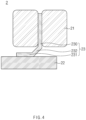
- FIG. 4 is a cross-sectional view illustrating a battery cell 21, a connection part 23, and a fixing part 22 of a battery module 2 according to another embodiment.
- the battery module 2 may include a plurality of battery cells 21, a connection part 23, and a fixing part 22, which have the same configuration of the battery module 1 described above.
- the connection part 23 may include a cell adhesion portion 230 and a fixed adhesion portion 231.
- connection part 23 may further include an inclined portion 232.
- the inclined portion 232 may be provided between the cell adhesion portion 230 and the fixed adhesion portion 231 so as to be inclined.
- the inclined portion 232 may include a shape inclined with respect to a longitudinal direction of the cell adhesion portion 230 and the fixed adhesion portion 231.
- the cell adhesion portion 230 and the fixed adhesion portion 231 may be perpendicular to each other, and the inclined portion 232 may include a shape inclined at an angle of 45 degrees with respect to the cell adhesion portion 230 and the fixed adhesion portion 231.
- the inclined portion 232 may buffer external force transmitted from the battery cell 21 to the fixing part to perform a function of reducing the tensile force between the fixed adhesion portion 231 and the fixing part 22.
- connection part 23 since the connection part 23 according to another embodiment further includes the inclined portion 232, damage of the battery cell 21 due to the swelling may be more minimized to prevent a secondary problem such as an explosion phenomenon that occurs due to the damage of the battery cell 21, from occurring.
Landscapes
- Chemical & Material Sciences (AREA)
- Chemical Kinetics & Catalysis (AREA)
- Electrochemistry (AREA)
- General Chemical & Material Sciences (AREA)
- Engineering & Computer Science (AREA)
- Manufacturing & Machinery (AREA)
- Physics & Mathematics (AREA)
- Algebra (AREA)
- General Physics & Mathematics (AREA)
- Mathematical Analysis (AREA)
- Mathematical Optimization (AREA)
- Pure & Applied Mathematics (AREA)
- Battery Mounting, Suspending (AREA)
Abstract
Description
- The present application claims the benefit of the priority of
Korean Patent Application No. 10-2022-0077843, filed on June 24, 2022 - The present invention relates to a battery module.
- In general, secondary batteries include nickelcadmium batteries, nickel-hydrogen batteries, lithium ion batteries, and lithium ion polymer batteries. Such a secondary battery is being applied to be used in small-sized products such as digital cameras, P-DVDs, MP3Ps, mobile phones, PDAs, portable game devices, power tools, E-bikes, and the like as well as large-sized products requiring high power such as electric vehicles and hybrid vehicles, power storage devices for storing surplus power or renewable energy, and backup power storage devices.
- In general, in order to manufacture the secondary battery, first, electrode active material slurry is applied to a positive electrode collector and a negative electrode collector to manufacture a positive electrode and a negative electrode. Then, the electrodes are stacked on both sides of a separator to form an electrode assembly. Also, the electrode assembly is accommodated in a battery case, and then the battery case is sealed after an electrolyte is injected therein.
- Such a secondary battery is classified into a pouch-type secondary battery and a can-type secondary battery according to a material of a case accommodating the electrode assembly. In the pouch-type secondary battery, an electrode assembly is accommodated in a pouch made of a flexible polymer material. Also, in the can-type secondary battery, an electrode assembly is accommodated in a case made of a metal or plastic material.
- In general, a pouch-type battery case is manufactured by performing press processing on a pouch film having flexibility to form a cup part. Then, when the cup part is formed, the secondary battery is manufactured by accommodating the electrode assembly inside the cup part and sealing a corner part, which is a peripheral portion of the cup part.
- Furthermore, a battery module is manufactured by coupling a plurality of secondary batteries and putting the secondary batteries, which are coupled to each other, in a case. Such a secondary battery, that is, a battery cell is accommodated inside the case and is connected and fixed to an inner surface of the case through an adhesive having a resin component.
- In a state in which the battery cell is coupled to the inner surface of the case through an adhesive, when a swelling phenomenon of the battery cell occurs, large tensile force acts on the case of the battery cell. Here, the swelling refers to a phenomenon in which a lithium ion electrolyte in the pouch is vaporized, and thus, the battery becomes convex due to a pressure. Particularly, in the case of the pouch-type battery cell, as described above, the pouch is constituted by a cup part forming an inner accommodation space and a corner part that is a sealing section around the cup part. Since a reduction in a thickness of a raw material of the corner part is greater than that of the cup part during a press molding process of the pouch, more tensile force is applied to the corner part when the tension is generated on an outer surface of the pouch.
- As a result, when the battery cell connected to the adhesive is pushed by the swelling, large tensile force is applied to the corner part, causing gas explosion or leakage of the battery cell. In order to prevent this phenomenon, there is a need for a battery module having an improved connection structure between the adhesive and the battery cell.
- An object of the present invention for solving the above problem is to provide a battery module that improves a structure of a connection part connecting the fixing part to the battery cell to prevent the battery cell from being damaged.
- A battery module according to an embodiment of the present invention include a case in which an accommodation space is defined, a plurality of battery cells disposed in the accommodation space, a fixing part provided on an inner bottom surface of the case, and a connection part comprising a cell adhesion portion disposed between the plurality of battery cells and a fixed adhesion portion connected to the cell adhesion portion and adhered to the fixing part.
- The plurality of battery cells may be stacked in a direction parallel to a bottom surface of the case, and the cell adhesion portion may be perpendicular to the bottom surface of the case.
- A longitudinal direction of the fixed adhesion portion may be perpendicular to that of the cell adhesion portion.
- Each of the plurality of battery cells and the fixing part may be spaced a predetermined distance from each other.
- The fixed adhesion portion may be disposed between the battery cell and the fixing part.
- A top surface of the fixed adhesion portion may be spaced apart from a bottom surface of the battery cell.
- The connection part may further include an inclined portion provided to be inclined between the cell adhesion portion and the fixed adhesion portion..
- The battery module may further include an adhesive pad configured to bond the plurality of battery cells to each other in a stacking direction of the plurality of battery cells.
- The adhesive pad and the cell adhesion portion may be alternately stacked in the stacking direction of the plurality of battery cells.
- The connection part may be provided in plurality.
- Thermal conductivity of the connection part may be greater than that of each of the battery cells.
- Thermal conductivity of the fixing part may be greater than that of each of the battery cells.
- According to the preferred embodiment of the present invention, the structure of the connection part connecting the fixing part to the battery cell may be improved to prevent the battery cell from being damaged and exploded, thereby improving the stability and lifespan of the battery module.
- In addition, the effects that are obvious to those skilled in the art may be predicted from the configurations according to the embodiment of the present invention.
- The following drawings attached in this specification illustrate a preferred embodiment of the present invention and function to make further understood the technical spirit of the present invention along with the detailed description of the invention, and thus, the present invention should not be construed as being limited to only the drawings.
-
FIG. 1 is a cross-sectional view of a battery module according to a comparative example. -
FIG. 2 is a cross-sectional view illustrating a state in which swelling occurs in a battery cell according to the comparative example. -
FIG. 3 is a cross-sectional view of a battery module according to an embodiment. -
FIG. 4 is a cross-sectional view illustrating a battery cell, a connection part, and a fixing part of a battery module according to another embodiment. - Hereinafter, preferred embodiments of the present invention will be described in detail with reference to the accompanying drawings so that those of ordinary skill in the art can easily carry out the present invention. However, the present invention may be implemented in several different forms and is not limited or restricted by the following examples.
- In order to clearly explain the present invention, detailed descriptions of portions that are irrelevant to the description or related known technologies that may unnecessarily obscure the gist of the present invention have been omitted, and in the present specification, reference symbols are added to components in each drawing. In this case, the same or similar reference numerals are assigned to the same or similar elements throughout the specification.
- Also, terms or words used in this specification and claims should not be restrictively interpreted as ordinary meanings or dictionary-based meanings, but should be interpreted as meanings and concepts conforming to the scope of the present invention on the basis of the principle that an inventor can properly define the concept of a term to describe and explain his or her invention in the best ways.
-
FIG. 1 is a cross-sectional view of a battery module according to a comparative example. - Referring to
FIG. 1 , a battery module according to a comparison example may include a case C1 and battery cells C2 provided inside the case C1. For example, the battery module according to the comparison example may include an adhesive layer C3 on an inner bottom surface of the case C1, and the plurality of battery cells C2 may be adhered and fixed through the adhesive layer C3. -
FIG. 2 is a cross-sectional view illustrating a state in which swelling occurs in the battery cell C2 according to the comparative example. - Referring to
FIG. 2 , in the structure of the comparative example, when a swelling phenomenon of the battery cell C2 occurs due to internal vaporization and damage of the battery cell C2, referring toFIG. 2 , in a state in which bottom surfaces of the plurality of battery cells are fixed to the adhesive layer C3, the battery cells C2 may receive external force to one side in a direction of an arrow inFIG. 2 . - When each of the battery cells C2 is a pouch-type battery constituted by a cup part and a corner part, since a reduction in thickness of the corner part is greater than that of the cup part during the press molding process of the pouch, when tension occurs at a connection part between the pouch and the adhesive layer C3, large tensile force may act on the corner part connected to the adhesive layer C3.
- Therefore, according to the structure according to the comparative example, when the swelling occurs, the possibility of damage to the corner part of the battery cell C2, which is vulnerable to the tension, may increase. As a result, an accident in which the battery module is exploded may occur due to discharge of an internal gas and flame due to the damage or destruction of the battery cell C2.
- In order to compensate for this problem, the
battery module 1 according to an embodiment of the present invention may include the following structures and functions. -
FIG. 3 is a cross-sectional view of abattery module 1 according to an embodiment. - Referring to
FIG. 3 , thebattery module 1 may accumulate electric energy by accommodating a plurality ofbattery cells 11 inside acase 10 and may output the accumulated electric energy to the outside by being connected to an external terminal. For example, thebattery module 1 may include acase 10 defining an accommodation space therein, and the plurality ofbattery cells 11 may be stacked on each other and disposed and fixed in the accommodation space. In this case, thebattery cell 11 may include a pouch, which are constituted by a cup part and a corner part, and an electrode assembly accommodated in the pouch. The cup part may refer to a portion formed to be recessed in a central portion of the pouch through a press-forming process of the pouch, and the corner part may refer to a side sealing part formed along a circumference of the cup part. - The
battery module 1 may prevent a plurality ofbattery cells 11 from being damaged due to swelling through a connection structure in which the plurality ofbattery cells 11 are connected to an inner surface of acase 10. In other words, thebattery module 1 may improve the connection structure in order to reduce damage of the corner part of the pouch of thebattery cells 11. In addition, thebattery module 1 may more effectively release heat generated in the plurality ofbattery cells 11 to the outside through the connection structure. - Specifically, the
battery module 1 may further include a fixingpart 12 and aconnection part 13. - The fixing
part 12 may fix the plurality ofbattery cells 11 to the inside of thecase 10. For example, the fixingpart 12 may be provided on an inner bottom surface of thecase 10 and be connected to the plurality ofbattery cells 11. Specifically, the bottom surface of the fixingpart 12 may be connected to the inner bottom surface of thecase 10, and the top surface of the fixingpart 12 may be connected to the plurality ofbattery cells 11. More specifically, a top surface of the fixingpart 12 may be connected to the plurality ofbattery cells 11 through theconnection part 13 to be described later. - The sealing
part 12 may include an adhesive material. For example, the fixingpart 12 may include a resin material and may be applied to an inner top surface of thecase 10 and then be solidified in a state of being adhered and connected to theconnection part 13 to be described later after being applied to the inner bottom surface of thecase 10 to connect the inner bottom surface of thecase 10 to the plurality ofbattery cells 11. - The
connection part 13 is connected to the plurality ofbattery cells 11 and the fixingpart 12 to connect the plurality ofbattery cells 11 to the fixingpart 12. For example, theconnection part 13 may be provided between the plurality ofbattery cells 11 to protrude from the plurality ofbattery cells 11 to one side in the state of being coupled to the plurality ofbattery cells 11 so as to be connected to the fixingpart 12, thereby connecting the plurality ofbattery cells 11 to the fixingpart 12. In this case, the plurality ofbattery cells 11 are connected to the fixingpart 12 only through theconnection part 13, and the plurality ofbattery cells 11 may not be in contact with the fixingpart 12. The plurality ofbattery cells 11 and the fixingpart 12 may be disposed to be spaced a predetermined distance from each other. - The
connection part 13 may include acell adhesion portion 130 and a fixedadhesion portion 131. - The
cell adhesion portion 130 may be disposed between the plurality ofbattery cells 11. For example, thecell adhesion portion 130 may be disposed between the plurality ofbattery cells 11 according to a direction in which the plurality ofbattery cells 11 are stacked. In this case, the plurality ofbattery cells 11 may be stacked in a direction parallel to the bottom surface of thecase 10. That is, since thecell adhesion portion 130 is disposed in a space between the plurality ofbattery cells 11, which are stacked, thecell adhesion portion 130 may include a structure in which thebattery cell 11 are coupled and connected to both sides thereof. - Specifically, a longitudinal direction of the
cell adhesion portion 130 may be perpendicular to a bottom surface of thecase 10. In other words, when viewed in a side view, thecell adhesion portion 130 may include a structure extending toward the top and bottom surfaces of thecase 10. Thecell adhesion portion 130 may protrude from the plurality ofbattery cells 11 to a bottom surface of thecase 10 in a state of being disposed and connected between the plurality ofbattery cells 11 and then may be connected to the fixedadhesion portion 131. - The fixed
adhesion portion 131 may be connected to thecell adhesion portion 130 and adhered to the fixingpart 12. For example, the top surface of the fixedadhesion portion 131 may be connected to a lower portion of thecell adhesion portion 130, and the bottom surface of the fixedadhesion portion 131 may be adhered to a top surface of the fixingpart 12. That is, the fixedadhesion portion 131 may be disposed between the plurality ofbattery cells 11 and the fixingpart 12 to connect thecell adhesion portion 130 to the fixingpart 12. - In this case, the fixed
adhesion portion 131 may not be in contact with the plurality ofbattery cells 11. Since the fixedadhesion portion 131 does not in contact with the plurality ofbattery cells 11, even if the plurality ofbattery cells 11 are pushed due to the swelling, the structure in which the fixedadhesion portion 131 and the plurality ofbattery cells 11 are disposed to be spaced apart from each other may allow the tensile force to act on thebattery cell 11 by the fixedadhesion portion 131 or prevent thebattery cell 11 from being damaged. - A longitudinal direction of the fixed
adhesion portion 131 may be perpendicular to the longitudinal direction of thecell adhesion portion 130. In other words, the fixedadhesion portion 131 may be vertically connected to thecell adhesion portion 130 and may be disposed to be arranged parallel to the bottom surface of thecase 10. For example, due to the structure of thecell adhesion portion 130 and the fixedadhesion portion 131, theconnection part 13 may include an 'L' shape. Specifically, when viewed in the side view, an adhesion length of the fixedadhesion portion 131 with the fixingpart 12 may be greater than a width of thecell adhesion portion 130. - According to the structure of the
connection part 13, when viewed in the side view, in a state in which theconnection part 13 is coupled between the plurality of stackedbattery cells 11, the bottom surface of theconnection part 13, i.e., the bottom surface of the fixedadhesion portion 131 may be in contact with and connected to the fixingpart 12 on a wider area. In other words, theconnection part 13 may be coupled to thebattery cell 11 on the wider area through thecell adhesion portion 130 and connected to the fixing part on the wider area through the fixingadhesion portion 131, and thus, the coupling force and fixing force between the plurality ofbattery cells 11 may increase. - Supplementally, since the
cell adhesion portion 130 is not limited to a specific area of the pouch of thebattery cell 11, but is coupled to thebattery cell 11 over the wide area including the cup part and the corner part of the pouch of thebattery cell 11, the tensile force due to the swelling may be dispersed to the wide area of the pouch of thebattery cell 11. Similarly, even if thebattery cell 11 is pushed by the swelling, since the fixedadhesion portion 131 is coupled to the fixingpart 12 on the wide area, the tensile force generated between the fixedadhesion portion 131 and the fixingpart 12 may be dispersed to the wide area. - Thus, the structure of the connecting
portion 13 as described above may prevent the pouch from being damaged due to concentration of the tensile force generated in the relatively weak corner part due to the swelling phenomenon. As a result, secondary problem situations such as the explosion of thebattery module 1 may be prevented from occurring. - Additionally, when high-temperature heat is generated in the
battery cell 11 by the swelling, in order to more effectively release the heat of thebattery cell 11, thermal conductivity of the fixingpart 12 and theconnection part 13 may be higher than that of thebattery cell 11. Specifically, the fixingpart 12 may include an adhesive made of a resin material having thermal conductivity greater than that of thebattery cell 11. In addition, theconnection part 13 may include a plate shape made of a metal material having thermal conductivity greater than that of thebattery cell 11. - The
connection part 13 may more effectively transfer the heat generated in thebattery cell 11 to the outside through the structural features of thecell adhesion portion 130 and the fixedadhesion portion 131 described above. In other words, in the case of the comparative example in which theconnection part 13 does not exist, the battery cell C2 may be directly connected to the adhesive layer C3, and the high-temperature heat generated due to the internal vaporization may be transferred to the adhesive layer C3. In this process, heat at one side of the battery cell C2 directly connected to the adhesive layer C3 may be immediately released through the adhesive layer C3, but heat at the other side of the battery cell C2, which is not connected to the adhesive layer C3, may not be released effectively. Unlike the comparative embodiment, since theconnection part 13 according to the present invention is disposed between the plurality ofbattery cells 11, is connected to the plurality ofbattery cells 11 on the wider area, and is relatively far apart from the fixingpart 12, the high-temperature heat generated in thebattery cell 11 may be more effectively released. - Additionally, in order to improve the damage prevention effect and the heat dissipation effect of the
connection part 13 and the fixingpart 13, theconnection part 13 may be provided in plurality, which are disposed between the plurality ofbattery cells 11, respectively. That is, while the fixingpart 12 is integrally formed on the inner bottom surface of thecase 10, theconnection part 13 may be provided in plurality to prevent each of thebattery cells 11 from being damaged and to effectively transfer the heat generated in eachbattery cell 11 to the fixingpart 12. - An
adhesive pad 14 may adhere the plurality ofbattery cells 11 according to the stacking direction of the plurality ofbattery cells 11. For example, theadhesive pad 14 may be disposed between thestacked battery cells 11 to allow the plurality ofbattery cells 11 to be in contact with and coupled to each other. That is, theadhesive pad 14 may have a longitudinal direction perpendicular to the bottom surface of thecase 10, like thecell adhesion portion 130. Specifically, in a state in which thebattery cell 11 is provided between thecell adhesion portion 130 and theadhesive pad 14, theadhesive pad 14 and thecell adhesion portion 130 may be alternately stacked with each other in the stacking direction of the plurality ofbattery cells 11. In other words, thebattery cell 11, thecell adhesion portion 130, thebattery cell 11, and the adhesive pad may be repeatedly stacked in the order. - Due to the function of the
adhesive pad 14 as described above, coupling force between the plurality ofbattery cells 11 may increase, and thus, the plurality ofbattery cells 11 may be more fixed to the inside of thecase 10, and the damage of thebattery cell 11 due to the swelling may be reduced. - Hereinafter, a
battery module 2 according to another embodiment in which the structure of the connection part is partially modified will be described. Details identical to the configuration and function of the battery module described above will be omitted below. -
FIG. 4 is a cross-sectional view illustrating abattery cell 21, aconnection part 23, and a fixingpart 22 of abattery module 2 according to another embodiment. - Referring to
FIG. 4 , thebattery module 2 according to another embodiment may include a plurality ofbattery cells 21, aconnection part 23, and a fixingpart 22, which have the same configuration of thebattery module 1 described above. In addition, theconnection part 23 according to another embodiment may include acell adhesion portion 230 and a fixedadhesion portion 231. - Additionally, the
connection part 23 according to another embodiment may further include aninclined portion 232. - The
inclined portion 232 may be provided between thecell adhesion portion 230 and the fixedadhesion portion 231 so as to be inclined. For example, theinclined portion 232 may include a shape inclined with respect to a longitudinal direction of thecell adhesion portion 230 and the fixedadhesion portion 231. In other words, thecell adhesion portion 230 and the fixedadhesion portion 231 may be perpendicular to each other, and theinclined portion 232 may include a shape inclined at an angle of 45 degrees with respect to thecell adhesion portion 230 and the fixedadhesion portion 231. - According to the structure of the
inclined portion 232, even if thebattery cell 21 is pushed by swelling, and tensile force is generated between the fixedadhesion portion 231 and a fixing part, theinclined portion 232 may buffer external force transmitted from thebattery cell 21 to the fixing part to perform a function of reducing the tensile force between the fixedadhesion portion 231 and the fixingpart 22. - As a result, since the
connection part 23 according to another embodiment further includes theinclined portion 232, damage of thebattery cell 21 due to the swelling may be more minimized to prevent a secondary problem such as an explosion phenomenon that occurs due to the damage of thebattery cell 21, from occurring. - The above-disclosed subject matter is to be considered illustrative, and not restrictive, and the appended claims are intended to cover all such modifications, enhancements, and other embodiments, which fall within the true spirit and scope of the present invention.
- Thus, the embodiment of the present invention is to be considered illustrative, and not restrictive, and the technical spirit of the present invention is not limited to the foregoing embodiment.
- Therefore, the scope of the present invention is defined not by the detailed description of the invention but by the appended claims, and all differences within the scope will be construed as being included in the present invention.
-
- 1:
- Battery module
- 10:
- Case
- 11:
- Battery cell
- 12:
- Fixing part
- 13:
- Connection part
- 14:
- Adhesive pad
- 130:
- Cell adhesion portion
- 131:
- Fixed adhesion portion
- 232:
- Inclined portion
Claims (12)
- A battery module comprising:a case in which an accommodation space is defined;a plurality of battery cells disposed in the accommodation space;a fixing part provided on an inner bottom surface of the case; anda connection part comprising a cell adhesion portion disposed between the plurality of battery cells and a fixed adhesion portion connected to the cell adhesion portion and adhered to the fixing part.
- The battery module of claim 1, wherein the plurality of battery cells are stacked in a direction parallel to a bottom surface of the case, and
the cell adhesion portion is perpendicular to the bottom surface of the case. - The battery module of claim 2, wherein a longitudinal direction of the fixed adhesion portion is perpendicular to that of the cell adhesion portion.
- The battery module of claim 1, wherein each of the plurality of battery cells and the fixing part are spaced a predetermined distance from each other.
- The battery module of claim 4, wherein the fixed adhesion portion is disposed between the battery cell and the fixing part.
- The battery module of claim 5, wherein a top surface of the fixed adhesion portion is spaced apart from a bottom surface of the battery cell.
- The battery module of claim 6, wherein the connection part further comprises an inclined portion provided to be inclined between the cell adhesion portion and the fixed adhesion portion.
- The battery module of claim 1, further comprising an adhesive pad configured to bond the plurality of battery cells to each other in a stacking direction of the plurality of battery cells.
- The battery module of claim 8, wherein the adhesive pad and the cell adhesion portion are alternately stacked in the stacking direction of the plurality of battery cells.
- The battery module of claim 1, wherein the connection part is provided in plurality.
- The battery module of claim 1, wherein thermal conductivity of the connection part is greater than that of each of the battery cells.
- The battery module of claim 1, wherein thermal conductivity of the fixing part is greater than that of each of the battery cells.
Applications Claiming Priority (2)
| Application Number | Priority Date | Filing Date | Title |
|---|---|---|---|
| KR1020220077843A KR102940522B1 (en) | 2022-06-24 | 2022-06-24 | Battery module |
| PCT/KR2023/008413 WO2023249339A1 (en) | 2022-06-24 | 2023-06-16 | Battery module |
Publications (2)
| Publication Number | Publication Date |
|---|---|
| EP4525158A1 true EP4525158A1 (en) | 2025-03-19 |
| EP4525158A4 EP4525158A4 (en) | 2025-08-13 |
Family
ID=89380261
Family Applications (1)
| Application Number | Title | Priority Date | Filing Date |
|---|---|---|---|
| EP23827456.7A Pending EP4525158A4 (en) | 2022-06-24 | 2023-06-16 | BATTERY MODULE |
Country Status (5)
| Country | Link |
|---|---|
| EP (1) | EP4525158A4 (en) |
| JP (1) | JP2025520517A (en) |
| KR (1) | KR102940522B1 (en) |
| CN (1) | CN119343818A (en) |
| WO (1) | WO2023249339A1 (en) |
Families Citing this family (1)
| Publication number | Priority date | Publication date | Assignee | Title |
|---|---|---|---|---|
| USD1070969S1 (en) * | 2024-06-23 | 2025-04-15 | Ningbo Skl International Co., Ltd. | Roller stamp |
Family Cites Families (11)
| Publication number | Priority date | Publication date | Assignee | Title |
|---|---|---|---|---|
| DE102010022908B4 (en) | 2010-06-07 | 2024-06-13 | Vitesco Technologies GmbH | Battery with temperature detection, as well as use of such a battery |
| US9196938B2 (en) * | 2010-07-06 | 2015-11-24 | Samsung Sdi Co., Ltd. | Battery module |
| JP2012248299A (en) * | 2011-05-25 | 2012-12-13 | Sanyo Electric Co Ltd | Battery module, battery system, electric vehicle, mobile object, power storage device and power supply device |
| KR102065748B1 (en) * | 2013-01-07 | 2020-01-14 | 에스케이이노베이션 주식회사 | Thermal pad for secondary battery and Battery module having the same |
| KR101783916B1 (en) * | 2014-10-30 | 2017-10-10 | 주식회사 엘지화학 | Battery Module and a Method of making the same |
| JP6494870B2 (en) * | 2015-09-08 | 2019-04-03 | エルジー・ケム・リミテッド | Battery module with improved cooling performance |
| EP3340365B1 (en) * | 2015-09-21 | 2020-04-22 | LG Chem, Ltd. | Battery module including array of cooling fins having different thicknesses |
| KR102317273B1 (en) * | 2017-12-12 | 2021-10-22 | 주식회사 엘지에너지솔루션 | Battery module having a crush plate and Method for manufacturing the same |
| KR20190082180A (en) * | 2019-07-01 | 2019-07-09 | 에스케이이노베이션 주식회사 | Secondary Battery Module |
| KR102857893B1 (en) * | 2019-11-01 | 2025-09-09 | 주식회사 엘지에너지솔루션 | Battery module and battery pack including the same |
| KR102383165B1 (en) | 2020-12-02 | 2022-04-08 | 주식회사 바디프랜드 | Massage apparatus having independently movable leg massage unit |
-
2022
- 2022-06-24 KR KR1020220077843A patent/KR102940522B1/en active Active
-
2023
- 2023-06-16 JP JP2024573820A patent/JP2025520517A/en active Pending
- 2023-06-16 CN CN202380044751.0A patent/CN119343818A/en active Pending
- 2023-06-16 WO PCT/KR2023/008413 patent/WO2023249339A1/en not_active Ceased
- 2023-06-16 EP EP23827456.7A patent/EP4525158A4/en active Pending
Also Published As
| Publication number | Publication date |
|---|---|
| WO2023249339A1 (en) | 2023-12-28 |
| KR102940522B1 (en) | 2026-03-18 |
| EP4525158A4 (en) | 2025-08-13 |
| CN119343818A (en) | 2025-01-21 |
| JP2025520517A (en) | 2025-07-03 |
| KR20240000974A (en) | 2024-01-03 |
Similar Documents
| Publication | Publication Date | Title |
|---|---|---|
| US9160039B2 (en) | Battery cell of excellent heat dissipation property and middle or large-sized battery module employed with the same | |
| KR101001320B1 (en) | Battery cell of improved thermal stability and medium and large battery module including the same | |
| KR101067627B1 (en) | Battery module with compact structure and excellent heat dissipation | |
| KR102058194B1 (en) | battery module | |
| EP3736883A1 (en) | Battery module including secondary battery and bus bar | |
| KR101098196B1 (en) | Battery Cell Having Improved Thermal Stability and Middle or Large-sized Battery Module Employed with the Same | |
| US12046731B2 (en) | Battery module, method for preparing the same and battery pack including the same | |
| US20130280576A1 (en) | Battery | |
| KR101825007B1 (en) | Pouch type secondary battery and method of fabricating the same | |
| JP7395231B2 (en) | Battery module and battery pack containing it | |
| KR102940522B1 (en) | Battery module | |
| KR20220043024A (en) | Pouch battery cell and battery module including the same | |
| EP4181274A1 (en) | Battery module and battery pack including same | |
| EP4693657A1 (en) | Battery pack and device including same | |
| EP4567990A1 (en) | Battery pack case and battery pack comprising same | |
| EP4560813A1 (en) | Battery pack case and battery pack including same | |
| KR20240000975A (en) | Battery module | |
| EP4708502A1 (en) | Cell assembly, battery module including same, and method for manufacturing cell assembly | |
| KR102920616B1 (en) | Battery cell and manufacturing device for the same | |
| CN116250116B (en) | Battery pack and apparatus including the battery pack | |
| EP4187689B1 (en) | Pouch battery cell and battery module including the same | |
| EP4175018A1 (en) | Battery cell and battery module having the same | |
| US20230070655A1 (en) | Battery Cell and Manufacturing Device for the Same | |
| EP3813145A1 (en) | Battery pack and device including same |
Legal Events
| Date | Code | Title | Description |
|---|---|---|---|
| STAA | Information on the status of an ep patent application or granted ep patent |
Free format text: STATUS: THE INTERNATIONAL PUBLICATION HAS BEEN MADE |
|
| PUAI | Public reference made under article 153(3) epc to a published international application that has entered the european phase |
Free format text: ORIGINAL CODE: 0009012 |
|
| STAA | Information on the status of an ep patent application or granted ep patent |
Free format text: STATUS: REQUEST FOR EXAMINATION WAS MADE |
|
| 17P | Request for examination filed |
Effective date: 20241212 |
|
| AK | Designated contracting states |
Kind code of ref document: A1 Designated state(s): AL AT BE BG CH CY CZ DE DK EE ES FI FR GB GR HR HU IE IS IT LI LT LU LV MC ME MK MT NL NO PL PT RO RS SE SI SK SM TR |
|
| A4 | Supplementary search report drawn up and despatched |
Effective date: 20250711 |
|
| RIC1 | Information provided on ipc code assigned before grant |
Ipc: H01M 50/242 20210101AFI20250707BHEP Ipc: H01M 50/211 20210101ALI20250707BHEP Ipc: H01M 10/655 20140101ALI20250707BHEP Ipc: H01M 10/651 20140101ALI20250707BHEP Ipc: H01M 10/6554 20140101ALI20250707BHEP Ipc: H01M 10/647 20140101ALI20250707BHEP Ipc: H01M 50/291 20210101ALI20250707BHEP |
|
| DAV | Request for validation of the european patent (deleted) | ||
| DAX | Request for extension of the european patent (deleted) | ||
| STAA | Information on the status of an ep patent application or granted ep patent |
Free format text: STATUS: EXAMINATION IS IN PROGRESS |
|
| 17Q | First examination report despatched |
Effective date: 20251209 |