EP4525147A2 - Secondary battery and electronic apparatus - Google Patents
Secondary battery and electronic apparatus Download PDFInfo
- Publication number
- EP4525147A2 EP4525147A2 EP24199847.5A EP24199847A EP4525147A2 EP 4525147 A2 EP4525147 A2 EP 4525147A2 EP 24199847 A EP24199847 A EP 24199847A EP 4525147 A2 EP4525147 A2 EP 4525147A2
- Authority
- EP
- European Patent Office
- Prior art keywords
- edge
- region
- secondary battery
- connecting portion
- sealing
- Prior art date
- Legal status (The legal status is an assumption and is not a legal conclusion. Google has not performed a legal analysis and makes no representation as to the accuracy of the status listed.)
- Pending
Links
Images



Classifications
-
- H—ELECTRICITY
- H01—ELECTRIC ELEMENTS
- H01M—PROCESSES OR MEANS, e.g. BATTERIES, FOR THE DIRECT CONVERSION OF CHEMICAL ENERGY INTO ELECTRICAL ENERGY
- H01M10/00—Secondary cells; Manufacture thereof
- H01M10/05—Accumulators with non-aqueous electrolyte
- H01M10/052—Li-accumulators
- H01M10/0525—Rocking-chair batteries, i.e. batteries with lithium insertion or intercalation in both electrodes; Lithium-ion batteries
-
- H—ELECTRICITY
- H01—ELECTRIC ELEMENTS
- H01M—PROCESSES OR MEANS, e.g. BATTERIES, FOR THE DIRECT CONVERSION OF CHEMICAL ENERGY INTO ELECTRICAL ENERGY
- H01M10/00—Secondary cells; Manufacture thereof
- H01M10/04—Construction or manufacture in general
- H01M10/0436—Small-sized flat cells or batteries for portable equipment
-
- H—ELECTRICITY
- H01—ELECTRIC ELEMENTS
- H01M—PROCESSES OR MEANS, e.g. BATTERIES, FOR THE DIRECT CONVERSION OF CHEMICAL ENERGY INTO ELECTRICAL ENERGY
- H01M10/00—Secondary cells; Manufacture thereof
- H01M10/05—Accumulators with non-aqueous electrolyte
- H01M10/058—Construction or manufacture
-
- H—ELECTRICITY
- H01—ELECTRIC ELEMENTS
- H01M—PROCESSES OR MEANS, e.g. BATTERIES, FOR THE DIRECT CONVERSION OF CHEMICAL ENERGY INTO ELECTRICAL ENERGY
- H01M50/00—Constructional details or processes of manufacture of the non-active parts of electrochemical cells other than fuel cells, e.g. hybrid cells
- H01M50/10—Primary casings; Jackets or wrappings
- H01M50/102—Primary casings; Jackets or wrappings characterised by their shape or physical structure
- H01M50/105—Pouches or flexible bags
-
- H—ELECTRICITY
- H01—ELECTRIC ELEMENTS
- H01M—PROCESSES OR MEANS, e.g. BATTERIES, FOR THE DIRECT CONVERSION OF CHEMICAL ENERGY INTO ELECTRICAL ENERGY
- H01M50/00—Constructional details or processes of manufacture of the non-active parts of electrochemical cells other than fuel cells, e.g. hybrid cells
- H01M50/10—Primary casings; Jackets or wrappings
- H01M50/183—Sealing members
- H01M50/186—Sealing members characterised by the disposition of the sealing members
-
- H—ELECTRICITY
- H01—ELECTRIC ELEMENTS
- H01M—PROCESSES OR MEANS, e.g. BATTERIES, FOR THE DIRECT CONVERSION OF CHEMICAL ENERGY INTO ELECTRICAL ENERGY
- H01M50/00—Constructional details or processes of manufacture of the non-active parts of electrochemical cells other than fuel cells, e.g. hybrid cells
- H01M50/50—Current conducting connections for cells or batteries
- H01M50/543—Terminals
- H01M50/547—Terminals characterised by the disposition of the terminals on the cells
- H01M50/55—Terminals characterised by the disposition of the terminals on the cells on the same side of the cell
-
- H—ELECTRICITY
- H01—ELECTRIC ELEMENTS
- H01M—PROCESSES OR MEANS, e.g. BATTERIES, FOR THE DIRECT CONVERSION OF CHEMICAL ENERGY INTO ELECTRICAL ENERGY
- H01M50/00—Constructional details or processes of manufacture of the non-active parts of electrochemical cells other than fuel cells, e.g. hybrid cells
- H01M50/50—Current conducting connections for cells or batteries
- H01M50/572—Means for preventing undesired use or discharge
- H01M50/584—Means for preventing undesired use or discharge for preventing incorrect connections inside or outside the batteries
- H01M50/586—Means for preventing undesired use or discharge for preventing incorrect connections inside or outside the batteries inside the batteries, e.g. incorrect connections of electrodes
-
- H—ELECTRICITY
- H01—ELECTRIC ELEMENTS
- H01M—PROCESSES OR MEANS, e.g. BATTERIES, FOR THE DIRECT CONVERSION OF CHEMICAL ENERGY INTO ELECTRICAL ENERGY
- H01M50/00—Constructional details or processes of manufacture of the non-active parts of electrochemical cells other than fuel cells, e.g. hybrid cells
- H01M50/50—Current conducting connections for cells or batteries
- H01M50/572—Means for preventing undesired use or discharge
- H01M50/584—Means for preventing undesired use or discharge for preventing incorrect connections inside or outside the batteries
- H01M50/59—Means for preventing undesired use or discharge for preventing incorrect connections inside or outside the batteries characterised by the protection means
- H01M50/593—Spacers; Insulating plates
-
- H—ELECTRICITY
- H01—ELECTRIC ELEMENTS
- H01M—PROCESSES OR MEANS, e.g. BATTERIES, FOR THE DIRECT CONVERSION OF CHEMICAL ENERGY INTO ELECTRICAL ENERGY
- H01M2220/00—Batteries for particular applications
- H01M2220/30—Batteries in portable systems, e.g. mobile phone, laptop
-
- H—ELECTRICITY
- H01—ELECTRIC ELEMENTS
- H01M—PROCESSES OR MEANS, e.g. BATTERIES, FOR THE DIRECT CONVERSION OF CHEMICAL ENERGY INTO ELECTRICAL ENERGY
- H01M50/00—Constructional details or processes of manufacture of the non-active parts of electrochemical cells other than fuel cells, e.g. hybrid cells
- H01M50/10—Primary casings; Jackets or wrappings
- H01M50/116—Primary casings; Jackets or wrappings characterised by the material
- H01M50/121—Organic material
-
- H—ELECTRICITY
- H01—ELECTRIC ELEMENTS
- H01M—PROCESSES OR MEANS, e.g. BATTERIES, FOR THE DIRECT CONVERSION OF CHEMICAL ENERGY INTO ELECTRICAL ENERGY
- H01M50/00—Constructional details or processes of manufacture of the non-active parts of electrochemical cells other than fuel cells, e.g. hybrid cells
- H01M50/10—Primary casings; Jackets or wrappings
- H01M50/116—Primary casings; Jackets or wrappings characterised by the material
- H01M50/124—Primary casings; Jackets or wrappings characterised by the material having a layered structure
-
- H—ELECTRICITY
- H01—ELECTRIC ELEMENTS
- H01M—PROCESSES OR MEANS, e.g. BATTERIES, FOR THE DIRECT CONVERSION OF CHEMICAL ENERGY INTO ELECTRICAL ENERGY
- H01M50/00—Constructional details or processes of manufacture of the non-active parts of electrochemical cells other than fuel cells, e.g. hybrid cells
- H01M50/10—Primary casings; Jackets or wrappings
- H01M50/183—Sealing members
- H01M50/19—Sealing members characterised by the material
- H01M50/193—Organic material
-
- Y—GENERAL TAGGING OF NEW TECHNOLOGICAL DEVELOPMENTS; GENERAL TAGGING OF CROSS-SECTIONAL TECHNOLOGIES SPANNING OVER SEVERAL SECTIONS OF THE IPC; TECHNICAL SUBJECTS COVERED BY FORMER USPC CROSS-REFERENCE ART COLLECTIONS [XRACs] AND DIGESTS
- Y02—TECHNOLOGIES OR APPLICATIONS FOR MITIGATION OR ADAPTATION AGAINST CLIMATE CHANGE
- Y02E—REDUCTION OF GREENHOUSE GAS [GHG] EMISSIONS, RELATED TO ENERGY GENERATION, TRANSMISSION OR DISTRIBUTION
- Y02E60/00—Enabling technologies; Technologies with a potential or indirect contribution to GHG emissions mitigation
- Y02E60/10—Energy storage using batteries
Definitions
- This application relates to the field of pouch battery technologies, and in particular, to a secondary battery and an electronic apparatus.
- Secondary batteries are widely used in electric vehicles and consumer electronic products due to their advantages such as high energy density, high output power, and long cycle life. However, secondary batteries are likely to pose safety issues such as fire in the case of abnormal situations such as dropping or collision.
- An objective of this application is to propose a secondary battery, which can reduce the risk of internal short circuits.
- a first aspect of this application provides a secondary battery including an electrode assembly, a packaging bag, and a fixing member.
- the packaging bag includes a first packaging portion and a second packaging portion disposed opposite to each other in a first direction.
- the first packaging portion includes a first region and a second region connected to each other.
- the second packaging portion includes a third region and a fourth region connected to each other.
- the second region and the fourth region are arranged in the first direction form a body portion for accommodating the electrode assembly, and the first region and the third region are arranged in the first direction form a sealing portion for sealing the body portion.
- the fixing member includes a fixing portion and a connecting portion connected to each other.
- the fixing portion surrounds the electrode assembly.
- the connecting portion is disposed between the first region and the third region, and viewed along the first direction, the connecting portion overlaps with the sealing portion.
- the fixing portion surrounds the electrode assembly to fasten the electrode assembly, reducing the risk of short circuits due to contact between adjacent positive electrode plate and negative electrode plate caused by shrinkage of a separator.
- the connecting portion is disposed between the first region and the third region, such that the fixing member is connected to the packaging bag via the connecting portion, which improves stability between the electrode assembly and the packaging bag and reduces the risk of sliding of the electrode assembly in the packaging bag.
- the connecting portion includes a first sealing layer, where the first sealing layer includes a first surface and a second surface disposed opposite to each other in the first direction.
- the connecting portion is connected to the first region via the first surface and connected to the third region via the second surface.
- the first sealing layer being connected to the first region and the third region can reduce manufacturing costs.
- the connecting portion is connected to the first region and the third region via the first surface.
- the connecting portion further includes a metal layer and a second sealing layer, where in the first direction, the first sealing layer, the metal layer, and the second sealing layer are stacked sequentially, and the connecting portion is connected to the first region via the first sealing layer and connected to the third region via the second sealing layer.
- the connecting portion further includes a metal layer and a second sealing layer, where in the first direction, the first sealing layer, the metal layer, and the second sealing layer are stacked sequentially, and the connecting portion is connected to the first region and the third region via the first sealing layer.
- the connecting portion and the fixing portion are integrally disposed or separately disposed.
- the first sealing layer and/or the second sealing layer includes at least one of polypropylene, modified polypropylene, polyethylene, ethylene-propylene copolymer, ethylene-vinyl acetate copolymer, or ethylene-ethyl acrylate copolymer.
- the secondary battery further includes a first adhesive layer, where the first adhesive layer is disposed on a surface of the fixing portion facing the packaging bag and is adhered to the body portion. This is conducive to reducing the risk of sliding of the electrode assembly in the packaging bag.
- the electrode assembly in a second direction perpendicular to the first direction, includes a first edge and a second edge located on a side opposite the first edge, and the first adhesive layer includes a third edge located on a side of the first edge and a fourth edge located on a side opposite the third edge and on a side of the second edge, where a distance by which the first edge extends beyond the third edge is greater than or equal to 2 mm.
- the first adhesive layer includes at least one of polyethylene, polypropylene, phenolic resin, melamine resin, unsaturated polyester resin, epoxy resin, silicone resin, or polyurethane.
- the first adhesive layer in a second direction, extends to the connecting portion; and viewed along the first direction, the first adhesive layer does not overlap with the sealing portion. This reduces the risk of the first adhesive layer being sealed into the sealing portion, improving the sealing reliability in the second direction.
- the first adhesive layer in the second direction, includes a third edge and a fourth edge located on a side opposite the third edge, and the connecting portion includes a fifth edge located on a side of the third edge and a sixth edge located on a side opposite the fifth edge and on a side of the fourth edge, where a distance between the third edge and the fifth edge is 2 mm to 10 mm. This is conducive to improving the sealing reliability.
- the secondary battery further includes a second adhesive layer, where the second adhesive layer is disposed on a surface of the fixing portion facing the electrode assembly and is adhered to the electrode assembly.
- the secondary battery further includes a first metal plate, a second metal plate, a first insulating layer, and a second insulating layer.
- the first metal plate is electrically connected to the electrode assembly and extends out of the packaging bag in a second direction through the sealing portion.
- the second metal plate is electrically connected to the electrode assembly and extends out of the packaging bag in the second direction through the sealing portion.
- the first insulating layer covers a surface of the first metal plate.
- the second insulating layer covers a surface of the second metal plate.
- the first metal plate, the second metal plate, and the connecting portion are located on a same side of the secondary battery.
- a distance between the first metal plate and the second metal plate is less than 1.5 mm, the first direction, the second direction, and the third direction being perpendicular to each other; and viewed along the first direction, the connecting portion overlaps with the first insulating layer and the second insulating layer, and the connecting portion includes a first face facing the first region and a second face facing the third region, where the first face is adhered to the first insulating layer, and the second face is adhered to the second insulating layer.
- the first metal plate and the second metal plate are isolated by the first insulating layer, the connecting portion, and the second insulating layer adhered, reducing the risk of short circuits due to contact between the first metal plate and the second metal plate.
- the connecting portion is located between the first metal plate and the second metal plate and does not overlap with the first insulating layer and the second insulating layer, the first direction, the second direction, and the third direction being perpendicular to each other.
- the connecting portion in the second direction, includes a fifth edge and a sixth edge located on a side opposite the fifth edge, and the sealing portion includes a seventh edge located on a side of the fifth edge and an eighth edge located on a side opposite the seventh edge and on a side of the sixth edge, where a distance by which the fifth edge extends beyond the seventh edge is L1. This is conducive to improving the sealing reliability.
- the sealing portion in the second direction, includes a seventh edge and an eighth edge located on a side opposite the seventh edge, and the first insulating layer includes a ninth edge located on a side of the seventh edge and a tenth edge located on a side opposite the ninth edge and on a side of the eighth edge, where a distance by which the ninth edge extends beyond the seventh edge is L2, and 0.05 mm ⁇ L2 ⁇ 2 mm.
- width of the fixing portion is 3 mm to 50 mm. This is conducive to improving the fastening effect of the fixing member on the electrode assembly.
- an area of an orthographic projection of the fixing portion on the electrode assembly is S1
- an area of an orthographic projection of the electrode assembly is S2, satisfying 15% ⁇ S1/S2 ⁇ 80%.
- the fixing member is provided in plurality, and viewed along the first direction, the plurality of fixing members intersect.
- a second aspect of this application provides an electronic apparatus including the secondary battery according to any one of the foregoing embodiments.
- first, second, third, and the like may be used herein to describe various elements, components, regions, layers, and/or portions, these elements, components, regions, layers, and/or portions should not be limited by these terms. These terms are used to distinguish one element, component, region, layer, or portion from another element, component, region, layer, or portion. Therefore, the first element, component, region, layer, or portion discussed below may be referred to as the second element, component, region, layer, or portion without departing from the teachings of the example embodiments.
- the element A being adhered to the element B means that the element A and the element B are heated to soften and melt for adhering.
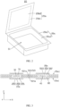
- FIG. 1 is a view of a secondary battery according to an embodiment of this application viewed along a first direction.
- a secondary battery 100 includes an electrode assembly 10, a packaging bag 20, a first metal plate 30, and a second metal plate 40.
- the electrode assembly 10 is accommodated in the packaging bag 20.
- the first metal plate 30 and the second metal plate 40 are both electrically connected to the electrode assembly 10, and extend out of the packaging bag 20 along a second direction Y to connect to an external element.
- the first metal plate 30 and the second metal plate 40 are located on a same side of the secondary battery 100 in the second direction Y. In other embodiments, the first metal plate 30 and the second metal plate 40 may be located on different sides of the secondary battery 100.
- FIG. 2 is a schematic diagram of a packaging bag before sealing.
- the packaging bag 20 includes a first packaging portion 20a and a second packaging portion 20b disposed opposite to each other in a first direction Z perpendicular to the second direction Y, and the first packaging portion 20a and the second packaging portion 20b are integrally disposed and sealed to form the packaging bag 20.
- the first packaging portion 20a includes a first region 20a1 and a second region 20a2 connected to each other, where three side edges of the second region 20a2 are surrounded by the first region 20a1.
- the second packaging portion 20b includes a third region 20b1 and a fourth region 20b2 connected to each other, where three side edges of the fourth region 20b2 are surrounded by the third region 20b1.
- the second region 20a2 and the fourth region 20b2 are arranged in the first direction Z.
- the fourth region 20b2 is substantially in a flat plate shape, the second region 20a2 is provided with a recess S1 for accommodating the electrode assembly 10, and the second region 20a2 and the fourth region 20b2 form a body portion 21 (referring to FIG. 1 ) for accommodating the electrode assembly 10.
- the first region 20a1 and the third region 20b1 are arranged in the first direction Z and are connected to form a sealing portion 22 (referring to FIG. 1 ) for sealing the body portion 21.
- the first metal plate 30 and the second metal plate 40 extend out of the packaging bag 20 through the sealing portion 22.
- FIG. 3 is a cross-sectional view along III-III in FIG. 1 .
- the packaging bag 20 has a film stacking structure.
- the first packaging portion 20a and the second packaging portion 20b both include a sealing layer 201, a metal layer 202, and a protective layer 203 stacked, where the sealing layer 201 is disposed close to the electrode assembly 10, and the protective layer 203 is disposed away from the electrode assembly 10 and exposed outside the secondary battery 100.
- the protective layer 203 may be made of polymer resin, which is used to protect the metal layer 202.
- the metal layer 202 may be made of aluminum, steel, or the like, which is used to prevent penetration of moisture from an external environment and enhance strength of the packaging bag 20.
- the sealing layer 201 may be made of a polymer, such as polypropylene or polyamide.
- the sealing layers 201 located in the first region 20a1 and the third region 20b1 may be directly connected through heat fusion to form the sealing portion 22.
- another fusible element is provided between the sealing layers 201 located in the first region 20a1 and the third region 20b1, allowing the sealing layers 201 located in the first region 20a1 and the third region 20b1 to be indirectly connected through heat fusion to form the sealing portion 22.
- the sealing layers 201 located in the first region 20a1 and the third region 20b1 are connected through adhesion to form the sealing portion 22, for example, an adhesive layer is disposed between the sealing layers 201 located in the first region 20a1 and the third region 20b1 and the sealing layers 201 are adhered together through the adhesive layer.
- the packaging bag 20 is an aluminum-plastic film or a steel-plastic film.
- FIG. 4 is a cross-sectional view along IV-IV in FIG. 1 .
- the electrode assembly 10 includes a first electrode plate 11, a second electrode plate 12, and a separator 13 disposed between the first electrode plate 11 and the second electrode plate 12.
- the first electrode plate 11, the separator 13, and the second electrode plate 12 are alternately stacked in the first direction Z to form a laminated structure.
- the first electrode plate 11, the separator 13, and the second electrode plate 12 are stacked and then wound to form a wound structure.
- the first electrode plate 11 includes a first current collector and a first active substance layer disposed on at least one surface of the first current collector.
- the second electrode plate 12 includes a second current collector and a second active substance layer disposed on at least one surface of the second current collector.
- the first electrode plate 11 is a positive electrode plate
- the second electrode plate 12 is a negative electrode plate.
- the first current collector and the second current collector both include at least one of Ni, Ti, Cu, Ag, Au, Pt, Fe, or Al.
- the first active substance layer includes a positive electrode active substance, and the positive electrode active substance may include at least one of lithium cobalt oxide, lithium manganese oxide, lithium nickel oxide, lithium nickel cobalt manganese oxide, lithium iron phosphate, lithium manganese iron phosphate, lithium vanadium phosphate, lithium vanadyl phosphate, lithium-rich manganese-based material, lithium nickel cobalt aluminate, or combinations thereof.
- the second active substance layer includes a negative electrode active substance, and the negative electrode active substance may be at least one selected from graphite materials, alloy materials, and lithium metal and alloys thereof.
- the graphite materials may be at least one selected from artificial graphite and natural graphite; and the alloy materials may be at least one selected from silicon, silicon oxide, tin, and titanium sulfide.
- the secondary battery 100 further includes a fixing member 50.
- the fixing member 50 includes a fixing portion 51 and a connecting portion 52 connected to each other.
- the fixing portion 51 surrounds the electrode assembly 10 and is configured to fasten the electrode assembly 10, reducing the risk of short circuits due to contact between the adjacent positive electrode plate and negative electrode plate caused by shrinkage of the separator 13.
- the connecting portion 52 is disposed between the first region 20a1 and the third region 20b 1; and viewed along the first direction Z, the connecting portion 52 overlaps with the sealing portion 22.
- the fixing member 50 is connected to the packaging bag 20 via the connecting portion 52, which improves stability between the electrode assembly 10 and the packaging bag 20 and reduces the risk of sliding of the electrode assembly 10 in the packaging bag 20, improving safety of the secondary battery 100.
- the fixing portion 51 and the connecting portion 52 are arranged in the second direction Y, and the connecting portion 52 overlaps with a portion of the sealing portion 22 located on a side of the electrode assembly 10 in the second direction Y.
- the connecting portion 52 includes a first sealing layer 521, where the first sealing layer 521 includes a first surface 521a and a second surface 521b disposed opposite to each other in the first direction Z, and the connecting portion 52 is connected to the sealing layer 201 in the first region 20a1 via the first surface 521a and connected to the sealing layer 201 in the third region 20b1 via the second surface 521b.
- the first sealing layer 521 and the sealing layer 201 may be adhered through heating to soften and melt. In other embodiments, the first sealing layer 521 and the sealing layer 201 are adhered through adhesion.
- the first sealing layer 521 includes at least one of polypropylene, modified polypropylene, polyethylene, ethylene-propylene copolymer, ethylene-vinyl acetate copolymer, or ethylene-ethyl acrylate copolymer.
- the secondary battery 100 further includes a first insulating layer 70 and a second insulating layer 80.
- the first insulating layer 70 covers a surface of the first metal plate 30, and the first metal plate 30 is connected to the first region 20a1 and third region 20b1 of the packaging bag 20 via the first insulating layer 70.
- the second insulating layer 80 covers a surface of the second metal plate 40, and the second metal plate 40 is connected to the first region 20a1 and third region 20b1 of the packaging bag 20 via the second insulating layer 80.
- the first metal plate 30, the second metal plate 40, and the connecting portion 52 are located on a same side of the secondary battery 100.
- the first insulating layer 70 and the second insulating layer 80 are spaced apart, and the connecting portion 52 is located between the first metal plate 30 and the second metal plate 40 and does not overlap with the first insulating layer 70 and the second insulating layer 80.
- the first insulating layer 70 and/or the second insulating layer 80 may include at least one of polyethylene, polypropylene, phenolic resin, melamine resin, unsaturated polyester resin, epoxy resin, silicone resin, or polyurethane.
- the first insulating layer 70 and the sealing layer 201 of the packaging bag 20 are adhered to connect the first insulating layer 70 to the first region 20a1 and the third region 20b 1; and the second insulating layer 80 and the sealing layer 201 of the packaging bag 20 are adhered to connect the second insulating layer 80 to the first region 20a1 and the third region 20b1.
- the first insulating layer 70 or the second insulating layer 80 may be connected to the packaging bag 20 through adhesion, for example, through an adhesive layer.
- the electrode assembly 10 in the second direction Y, includes a first edge 10a and a second edge 10b located on a side opposite the first edge 10a, the connecting portion 52 includes a fifth edge 52a located on a side of the first edge 10a and a sixth edge 52b located on a side opposite the fifth edge 52a and on a side of the second edge 10b, the sealing portion 22 includes a seventh edge 22a located on a side of the first edge 10a and an eighth edge 22b located on a side opposite the seventh edge 22a and on a side of the second edge 10b, and the first insulating layer 70 includes a ninth edge 70a located on a side of the first edge 10a and a tenth edge 70b located on a side opposite the ninth edge 70a and on a side of the second edge 10b.
- a distance by which the fifth edge 52a extends beyond the seventh edge 22a is L1
- a distance by which the ninth edge 70a extends beyond the seventh edge 22a is L2
- L1 and L2 falling within the foregoing ranges is conducive to improving sealing reliability.
- width of the fixing portion 51 is W, and 3 mm ⁇ W ⁇ 50 mm.
- the width W of the fixing portion 51 falling within the foregoing range is conducive to improving the fastening effect of the fixing member 50 on the electrode assembly 10.
- an area of an orthographic projection of the fixing portion 51 on the electrode assembly 10 is S1 mm 2
- an area of an orthographic projection of the electrode assembly 10 is S2 mm 2
- FIG. 5 is a cross-sectional view of a secondary battery according to another embodiment of this application, where the cross-sectional position is the same as that in FIG. 3 .
- the connecting portion 52 in the first direction Z, includes two first sealing layers 521 integrally disposed, where the two first sealing layers 521 are in contact with each other via the second surfaces 521b, and the first surfaces 521a are exposed outside the two first sealing layers 521.
- the connecting portion 52 is connected to the sealing layers 201 in the first region 20a1 and the third region 20b1 via the first surfaces 521a.
- FIG. 6 is a cross-sectional view of a secondary battery according to still another embodiment of this application, where the cross-sectional position is the same as that in FIG. 3 .
- the connecting portion 52 further includes a metal layer 522 and a second sealing layer 523.
- the first sealing layer 521, the metal layer 522, and the second sealing layer 523 are stacked sequentially.
- the metal layer 522 is in contact with the second surface 521b of the first sealing layer 521.
- the connecting portion 52 is connected to the sealing layer 201 in the first region 20a1 via the first surface 521a of the first sealing layer 521 and connected to the sealing layer 201 in the third region 20b1 via a surface of the second sealing layer 523 facing away from the metal layer 522.
- the second sealing layer 523 includes at least one of polypropylene, modified polypropylene, polyethylene, ethylene-propylene copolymer, ethylene-vinyl acetate copolymer, or ethylene-ethyl acrylate copolymer.
- the metal layer 522 is used to enhance rigidity of the fixing member 50, and the metal layer 522 may be made of aluminum, steel, or the like.
- FIG. 7 is a cross-sectional view of a secondary battery according to still another embodiment of this application, where the cross-sectional position is the same as that in FIG. 3 .
- the connecting portion 52 in the first direction Z, includes two first sealing layers 521 integrally disposed, two metal layers 522 integrally disposed between the two first sealing layers 521, and two second sealing layers 523 integrally disposed between the two metal layers 522.
- the adjacent first sealing layer 521, metal layer 522, and second sealing layer 523 are stacked sequentially.
- the metal layer 522 is in contact with the second surface 521b of the first sealing layer 521. Two surfaces of the two second sealing layers 523 facing away from the two metal layers 522 are connected.
- the connecting portion 52 is connected to the sealing layers 201 in the first region 20a1 and the third region 20b1 via the first surfaces 521a of the first sealing layers 521.
- the fixing portion 51 and the connecting portion 52 are integrally disposed. Specifically, in the first direction Z, the fixing portion 51 also includes two first sealing layers 521, two metal layers 522 located between the two first sealing layers 521, and two second sealing layers 523 located between the two metal layers 522, where the second sealing layer 523 of the fixing portion 51 is in contact with the electrode assembly 10.
- the fixing member 50 may be an aluminum-plastic film or a steel-plastic film. In other embodiments, the fixing portion 51 and the connecting portion 52 are separately disposed, and the fixing portion 51 and the connecting portion 52 are individually formed and connected to form the fixing member 50.
- the fixing portion 51 and the connecting portion 52 may be made of the same or different materials.
- FIG. 8 is a cross-sectional view of a secondary battery according to still another embodiment of this application, where the cross-sectional position is the same as that in FIG. 7 .
- a distance between the first metal plate 30 and the second metal plate 40 is less than 1.5 mm, which is conducive to reducing width of the secondary battery 100 in the third direction X, meeting the requirements for miniaturization.
- the first insulating layer 70 and the second insulating layer 80 are spaced apart in the first direction Z.
- the connecting portion 52 is disposed between the first insulating layer 70 and the second insulating layer 80; and viewed along the first direction Z, the connecting portion 52 overlaps with the first insulating layer 70 and the second insulating layer 80.
- the connecting portion 52 includes a first face 52d facing the first region 20a1 and a second face 52c facing the third region 20b1, where the first face 52d is adhered to the first insulating layer 70, and the second face 52c is adhered to the second insulating layer 80.
- the first metal plate 30 and the second metal plate 40 are isolated by the first insulating layer 70, the connecting portion 52, and the second insulating layer 80 adhered, reducing the risk of short circuits due to contact between the first metal plate 30 and the second metal plate 40.
- FIG. 9 is a cross-sectional view of a secondary battery according to still another embodiment of this application, where the cross-sectional position is the same as that in FIG. 4 .
- the secondary battery 100 further includes a first adhesive layer 61.
- the first adhesive layer 61 is disposed on a surface of the fixing portion 51 facing the packaging bag 20 and adhered to the body portion 21, to fix the electrode assembly 10 to the packaging bag 20, which reduces the risk of sliding of the electrode assembly 10 in the packaging bag 20, improving the safety performance.
- the secondary battery 100 further includes a second adhesive layer 62.
- the second adhesive layer 62 is disposed on a surface of the fixing portion 51 facing the electrode assembly 10 and adhered to the electrode assembly 10, enhancing the fixing effect of the fixing member 50 on the electrode assembly 10.
- the first adhesive layer 61 and/or the second adhesive layer 62 includes at least one of polyethylene, polypropylene, phenolic resin, melamine resin, unsaturated polyester resin, epoxy resin, silicone resin, or polyurethane.
- the first adhesive layer 61 and/or the second adhesive layer 62 may be a hot-melt adhesive, a double-sided adhesive, or the like.
- the electrode assembly 10 in the second direction Y, includes a first edge 10a and a second edge 10b located on a side opposite the first edge 10a, the first adhesive layer 61 includes a third edge 61a located on a side of the first edge 10a and a fourth edge 61b located on a side opposite the third edge 61a and on a side of the second edge 10b, and the connecting portion 52 includes a fifth edge 52a located on a side of the first edge 10a and a sixth edge 52b located on a side opposite the fifth edge 52a and on a side of the second edge 10b.
- a distance between the first edge 10a and the fifth edge 52a is less than a distance between the third edge 61a and the fifth edge 52a, and a distance by which the first edge 10a extends beyond the third edge 61a is greater than or equal to 2 mm, for example, 2 mm, 3 mm, 4 mm, or 5 mm.
- the distance by which the first edge 10a extends beyond the third edge 61a falling within the foregoing range can reduce the risk of the first adhesive layer 61 overflowing to the sealing portion 22 under the conditions of formation heating and pressurization, improving the sealing reliability.
- FIG. 10 is a cross-sectional view of a secondary battery according to still another embodiment of this application, where the cross-sectional position is the same as that in FIG. 4 .
- the first adhesive layer 61 extends to the connecting portion 52.
- the first adhesive layer 61 does not overlap with the sealing portion 22, which reduces the risk of the first adhesive layer 61 being sealed into the sealing portion 22, improving the sealing reliability.
- the distance between the third edge 61a and the fifth edge 52a is 2 mm to 10 mm, for example, 2 mm, 3 mm, 4 mm, 5 mm, 6 mm, 7 mm, 8 mm, 9 mm, or 10 mm.
- the fixing member 50 is provided in plurality. Viewed along the first direction Z, the plurality of fixing members 50 intersect in different directions. Viewed along the first direction Z, the plurality of fixing members 50 may intersect in a cross shape, a " ⁇ " shape, a "#" shape, a "*" shape, or the like.
- FIG. 11 shows the situation where two fixing members 50 intersect in a cross shape.
- the fixing portion 51 of one fixing member 50 surrounds two opposite surfaces of the electrode assembly 10 in the first direction Z and two opposite surfaces of the electrode assembly 10 in the second direction Y, and the connecting portion 52 of the fixing member 50 extends along the second direction Y from an edge of the fixing portion 51 of the fixing member 50 in the second direction Y.
- An embodiment of this application further provides an electronic apparatus including any one of the foregoing secondary batteries.
- the electronic apparatus of this application may be but is not limited to a notebook computer, a pen-input computer, a mobile computer, an electronic book player, a portable telephone, a portable fax machine, a portable copier, a portable printer, a stereo headset, a video recorder, a liquid crystal television, a portable cleaner, a portable CD player, a mini-disc, a transceiver, an electronic notebook, a calculator, a storage card, a portable recorder, a radio, a standby power source, a motor, an automobile, a motorcycle, a motor bicycle, a lighting appliance, a toy, a game console, a clock, an electric tool, a flash lamp, a camera, a large household battery, or a lithium-ion capacitor.
Landscapes
- Chemical & Material Sciences (AREA)
- Chemical Kinetics & Catalysis (AREA)
- Electrochemistry (AREA)
- General Chemical & Material Sciences (AREA)
- Engineering & Computer Science (AREA)
- Manufacturing & Machinery (AREA)
- Materials Engineering (AREA)
- Sealing Battery Cases Or Jackets (AREA)
- Battery Mounting, Suspending (AREA)
Abstract
Description
- This application relates to the field of pouch battery technologies, and in particular, to a secondary battery and an electronic apparatus.
- Secondary batteries are widely used in electric vehicles and consumer electronic products due to their advantages such as high energy density, high output power, and long cycle life. However, secondary batteries are likely to pose safety issues such as fire in the case of abnormal situations such as dropping or collision.
- An objective of this application is to propose a secondary battery, which can reduce the risk of internal short circuits.
- A first aspect of this application provides a secondary battery including an electrode assembly, a packaging bag, and a fixing member. The packaging bag includes a first packaging portion and a second packaging portion disposed opposite to each other in a first direction. The first packaging portion includes a first region and a second region connected to each other. The second packaging portion includes a third region and a fourth region connected to each other. The second region and the fourth region are arranged in the first direction form a body portion for accommodating the electrode assembly, and the first region and the third region are arranged in the first direction form a sealing portion for sealing the body portion. The fixing member includes a fixing portion and a connecting portion connected to each other. The fixing portion surrounds the electrode assembly. The connecting portion is disposed between the first region and the third region, and viewed along the first direction, the connecting portion overlaps with the sealing portion.
- In the secondary battery provided in this application, the fixing portion surrounds the electrode assembly to fasten the electrode assembly, reducing the risk of short circuits due to contact between adjacent positive electrode plate and negative electrode plate caused by shrinkage of a separator. In addition, the connecting portion is disposed between the first region and the third region, such that the fixing member is connected to the packaging bag via the connecting portion, which improves stability between the electrode assembly and the packaging bag and reduces the risk of sliding of the electrode assembly in the packaging bag.
- According to some embodiments of this application, the connecting portion includes a first sealing layer, where the first sealing layer includes a first surface and a second surface disposed opposite to each other in the first direction.
- According to some embodiments of this application, the connecting portion is connected to the first region via the first surface and connected to the third region via the second surface. The first sealing layer being connected to the first region and the third region can reduce manufacturing costs.
- According to some embodiments of this application, the connecting portion is connected to the first region and the third region via the first surface.
- According to some embodiments of this application, the connecting portion further includes a metal layer and a second sealing layer, where in the first direction, the first sealing layer, the metal layer, and the second sealing layer are stacked sequentially, and the connecting portion is connected to the first region via the first sealing layer and connected to the third region via the second sealing layer.
- According to some embodiments of this application, the connecting portion further includes a metal layer and a second sealing layer, where in the first direction, the first sealing layer, the metal layer, and the second sealing layer are stacked sequentially, and the connecting portion is connected to the first region and the third region via the first sealing layer.
- According to some embodiments of this application, the connecting portion and the fixing portion are integrally disposed or separately disposed.
- According to some embodiments of this application, the first sealing layer and/or the second sealing layer includes at least one of polypropylene, modified polypropylene, polyethylene, ethylene-propylene copolymer, ethylene-vinyl acetate copolymer, or ethylene-ethyl acrylate copolymer.
- According to some embodiments of this application, the secondary battery further includes a first adhesive layer, where the first adhesive layer is disposed on a surface of the fixing portion facing the packaging bag and is adhered to the body portion. This is conducive to reducing the risk of sliding of the electrode assembly in the packaging bag.
- According to some embodiments of this application, in a second direction perpendicular to the first direction, the electrode assembly includes a first edge and a second edge located on a side opposite the first edge, and the first adhesive layer includes a third edge located on a side of the first edge and a fourth edge located on a side opposite the third edge and on a side of the second edge, where a distance by which the first edge extends beyond the third edge is greater than or equal to 2 mm. This reduces the risk of the first adhesive layer overflowing to the sealing portion under the conditions of formation heating and pressurization, improving sealing reliability.
- According to some embodiments of this application, the first adhesive layer includes at least one of polyethylene, polypropylene, phenolic resin, melamine resin, unsaturated polyester resin, epoxy resin, silicone resin, or polyurethane.
- According to some embodiments of this application, in a second direction, the first adhesive layer extends to the connecting portion; and viewed along the first direction, the first adhesive layer does not overlap with the sealing portion. This reduces the risk of the first adhesive layer being sealed into the sealing portion, improving the sealing reliability in the second direction.
- According to some embodiments of this application, in the second direction, the first adhesive layer includes a third edge and a fourth edge located on a side opposite the third edge, and the connecting portion includes a fifth edge located on a side of the third edge and a sixth edge located on a side opposite the fifth edge and on a side of the fourth edge, where a distance between the third edge and the fifth edge is 2 mm to 10 mm. This is conducive to improving the sealing reliability.
- According to some embodiments of this application, the secondary battery further includes a second adhesive layer, where the second adhesive layer is disposed on a surface of the fixing portion facing the electrode assembly and is adhered to the electrode assembly.
- According to some embodiments of this application, the secondary battery further includes a first metal plate, a second metal plate, a first insulating layer, and a second insulating layer. The first metal plate is electrically connected to the electrode assembly and extends out of the packaging bag in a second direction through the sealing portion. The second metal plate is electrically connected to the electrode assembly and extends out of the packaging bag in the second direction through the sealing portion. The first insulating layer covers a surface of the first metal plate. The second insulating layer covers a surface of the second metal plate.
- According to some embodiments of this application, viewed along the first direction, the first metal plate, the second metal plate, and the connecting portion are located on a same side of the secondary battery.
- According to some embodiments of this application, in a third direction, a distance between the first metal plate and the second metal plate is less than 1.5 mm, the first direction, the second direction, and the third direction being perpendicular to each other; and viewed along the first direction, the connecting portion overlaps with the first insulating layer and the second insulating layer, and the connecting portion includes a first face facing the first region and a second face facing the third region, where the first face is adhered to the first insulating layer, and the second face is adhered to the second insulating layer. The first metal plate and the second metal plate are isolated by the first insulating layer, the connecting portion, and the second insulating layer adhered, reducing the risk of short circuits due to contact between the first metal plate and the second metal plate.
- According to some embodiments of this application, viewed along the first direction, in a third direction, the connecting portion is located between the first metal plate and the second metal plate and does not overlap with the first insulating layer and the second insulating layer, the first direction, the second direction, and the third direction being perpendicular to each other.
- According to some embodiments of this application, in the second direction, the connecting portion includes a fifth edge and a sixth edge located on a side opposite the fifth edge, and the sealing portion includes a seventh edge located on a side of the fifth edge and an eighth edge located on a side opposite the seventh edge and on a side of the sixth edge, where a distance by which the fifth edge extends beyond the seventh edge is L1. This is conducive to improving the sealing reliability.
- According to some embodiments of this application, in the second direction, the sealing portion includes a seventh edge and an eighth edge located on a side opposite the seventh edge, and the first insulating layer includes a ninth edge located on a side of the seventh edge and a tenth edge located on a side opposite the ninth edge and on a side of the eighth edge, where a distance by which the ninth edge extends beyond the seventh edge is L2, and 0.05 mm ≤ L2 ≤ 2 mm.
- According to some embodiments of this application, in a third direction perpendicular to the first direction, width of the fixing portion is 3 mm to 50 mm. This is conducive to improving the fastening effect of the fixing member on the electrode assembly.
- According to some embodiments of this application, in the first direction, an area of an orthographic projection of the fixing portion on the electrode assembly is S1, and an area of an orthographic projection of the electrode assembly is S2, satisfying 15% ≤ S1/S2 ≤ 80%.
- According to some embodiments of this application, the fixing member is provided in plurality, and viewed along the first direction, the plurality of fixing members intersect.
- A second aspect of this application provides an electronic apparatus including the secondary battery according to any one of the foregoing embodiments.
-
-
FIG. 1 is a view of a secondary battery according to an embodiment of this application viewed along a first direction. -
FIG. 2 is a schematic diagram of a packaging bag before sealing according to an embodiment of this application. -
FIG. 3 is a cross-sectional view of the secondary battery inFIG. 1 along III-III. -
FIG. 4 is a cross-sectional view of the secondary battery inFIG. 1 along IV-IV. -
FIG. 5 is a schematic cross-sectional view of a secondary battery according to another embodiment of this application. -
FIG. 6 is a schematic cross-sectional view of a secondary battery according to still another embodiment of this application. -
FIG. 7 is a schematic cross-sectional view of a secondary battery according to still another embodiment of this application. -
FIG. 8 is a schematic cross-sectional view of a secondary battery according to still another embodiment of this application. -
FIG. 9 is a schematic cross-sectional view of a secondary battery according to still another embodiment of this application. -
FIG. 10 is a schematic cross-sectional view of a secondary battery according to still another embodiment of this application. -
FIG. 11 is a view of a secondary battery according to still another embodiment of this application viewed along a first direction. - This application will be further described with reference to the accompanying drawings in the following specific embodiments.
- The following clearly and in detail describes the technical solutions in some embodiments of this application. Apparently, the described embodiments are some rather than all of the embodiments of this application. Unless otherwise defined, all technical and scientific terms used herein shall have the same meanings as commonly understood by persons skilled in the art to which this application belongs. The terms used in the specification of this application are for description of specific embodiments only without any intention to limit this application.
- The following describes some embodiments of this application in detail. However, this application may be embodied in many different implementations and should not be construed as being limited to the example embodiments set forth herein. Rather, these example embodiments are provided such that this application can be conveyed to persons skilled in the art thoroughly and in detail.
- In addition, in the accompanying drawings, sizes or thicknesses of various components and layers may be enlarged for brevity and clarity. Throughout the text, the same numerical values represent the same elements. As used herein, the term "and/or" includes any and all combinations of one or more associated items listed. In addition, it should be understood that when an element A is referred to as being "connected to" an element B, the element A may be directly connected to the element B, or an intervening element C may be present therebetween such that the element A and the element B are indirectly connected to each other.
- Further, the use of "may" in the descriptions of some embodiments of this application means "one or more embodiments of this application".
- The terminology used herein is merely intended to describe specific embodiments but not intended to constitute any limitation on this application. As used herein, the singular forms are intended to also include the plural forms, unless otherwise clearly stated in the context. It should be further understood that the term "include", when used in this specification, specifies the presence of stated features, numbers, steps, operations, elements, and/or components but does not preclude the presence or addition of one or more other features, numbers, steps, operations, elements, components, and/or combinations thereof.
- It should be understood that although the terms first, second, third, and the like may be used herein to describe various elements, components, regions, layers, and/or portions, these elements, components, regions, layers, and/or portions should not be limited by these terms. These terms are used to distinguish one element, component, region, layer, or portion from another element, component, region, layer, or portion. Therefore, the first element, component, region, layer, or portion discussed below may be referred to as the second element, component, region, layer, or portion without departing from the teachings of the example embodiments.
- In this application, the element A being adhered to the element B means that the element A and the element B are heated to soften and melt for adhering.
-
FIG. 1 is a view of a secondary battery according to an embodiment of this application viewed along a first direction. Referring toFIG. 1 , asecondary battery 100 includes anelectrode assembly 10, apackaging bag 20, afirst metal plate 30, and asecond metal plate 40. Theelectrode assembly 10 is accommodated in thepackaging bag 20. Thefirst metal plate 30 and thesecond metal plate 40 are both electrically connected to theelectrode assembly 10, and extend out of thepackaging bag 20 along a second direction Y to connect to an external element. In this embodiment, thefirst metal plate 30 and thesecond metal plate 40 are located on a same side of thesecondary battery 100 in the second direction Y. In other embodiments, thefirst metal plate 30 and thesecond metal plate 40 may be located on different sides of thesecondary battery 100. -
FIG. 2 is a schematic diagram of a packaging bag before sealing. Referring toFIG. 2 , thepackaging bag 20 includes afirst packaging portion 20a and asecond packaging portion 20b disposed opposite to each other in a first direction Z perpendicular to the second direction Y, and thefirst packaging portion 20a and thesecond packaging portion 20b are integrally disposed and sealed to form thepackaging bag 20. Thefirst packaging portion 20a includes a first region 20a1 and a second region 20a2 connected to each other, where three side edges of the second region 20a2 are surrounded by the first region 20a1. Thesecond packaging portion 20b includes a third region 20b1 and a fourth region 20b2 connected to each other, where three side edges of the fourth region 20b2 are surrounded by the third region 20b1. The second region 20a2 and the fourth region 20b2 are arranged in the first direction Z. The fourth region 20b2 is substantially in a flat plate shape, the second region 20a2 is provided with a recess S1 for accommodating theelectrode assembly 10, and the second region 20a2 and the fourth region 20b2 form a body portion 21 (referring toFIG. 1 ) for accommodating theelectrode assembly 10. The first region 20a1 and the third region 20b1 are arranged in the first direction Z and are connected to form a sealing portion 22 (referring toFIG. 1 ) for sealing the body portion 21. Thefirst metal plate 30 and thesecond metal plate 40 extend out of thepackaging bag 20 through the sealingportion 22. -
FIG. 3 is a cross-sectional view along III-III inFIG. 1 . Referring toFIG. 3 together, thepackaging bag 20 has a film stacking structure. Specifically, thefirst packaging portion 20a and thesecond packaging portion 20b both include asealing layer 201, ametal layer 202, and aprotective layer 203 stacked, where thesealing layer 201 is disposed close to theelectrode assembly 10, and theprotective layer 203 is disposed away from theelectrode assembly 10 and exposed outside thesecondary battery 100. Theprotective layer 203 may be made of polymer resin, which is used to protect themetal layer 202. Themetal layer 202 may be made of aluminum, steel, or the like, which is used to prevent penetration of moisture from an external environment and enhance strength of thepackaging bag 20. Thesealing layer 201 may be made of a polymer, such as polypropylene or polyamide. The sealing layers 201 located in the first region 20a1 and the third region 20b1 may be directly connected through heat fusion to form the sealingportion 22. In other embodiments, another fusible element is provided between the sealinglayers 201 located in the first region 20a1 and the third region 20b1, allowing the sealing layers 201 located in the first region 20a1 and the third region 20b1 to be indirectly connected through heat fusion to form the sealingportion 22. In another embodiment, the sealinglayers 201 located in the first region 20a1 and the third region 20b1 are connected through adhesion to form the sealingportion 22, for example, an adhesive layer is disposed between the sealinglayers 201 located in the first region 20a1 and the third region 20b1 and the sealing layers 201 are adhered together through the adhesive layer. In this embodiment, thepackaging bag 20 is an aluminum-plastic film or a steel-plastic film. -
FIG. 4 is a cross-sectional view along IV-IV inFIG. 1 . Referring toFIG. 4 , theelectrode assembly 10 includes afirst electrode plate 11, asecond electrode plate 12, and aseparator 13 disposed between thefirst electrode plate 11 and thesecond electrode plate 12. Thefirst electrode plate 11, theseparator 13, and thesecond electrode plate 12 are alternately stacked in the first direction Z to form a laminated structure. In other embodiments, thefirst electrode plate 11, theseparator 13, and thesecond electrode plate 12 are stacked and then wound to form a wound structure. - The
first electrode plate 11 includes a first current collector and a first active substance layer disposed on at least one surface of the first current collector. Thesecond electrode plate 12 includes a second current collector and a second active substance layer disposed on at least one surface of the second current collector. In this embodiment, thefirst electrode plate 11 is a positive electrode plate, and thesecond electrode plate 12 is a negative electrode plate. The first current collector and the second current collector both include at least one of Ni, Ti, Cu, Ag, Au, Pt, Fe, or Al. The first active substance layer includes a positive electrode active substance, and the positive electrode active substance may include at least one of lithium cobalt oxide, lithium manganese oxide, lithium nickel oxide, lithium nickel cobalt manganese oxide, lithium iron phosphate, lithium manganese iron phosphate, lithium vanadium phosphate, lithium vanadyl phosphate, lithium-rich manganese-based material, lithium nickel cobalt aluminate, or combinations thereof. The second active substance layer includes a negative electrode active substance, and the negative electrode active substance may be at least one selected from graphite materials, alloy materials, and lithium metal and alloys thereof. The graphite materials may be at least one selected from artificial graphite and natural graphite; and the alloy materials may be at least one selected from silicon, silicon oxide, tin, and titanium sulfide. - Referring to
FIG. 1 ,FIG. 3 , andFIG. 4 , thesecondary battery 100 further includes a fixingmember 50. The fixingmember 50 includes a fixingportion 51 and a connectingportion 52 connected to each other. The fixingportion 51 surrounds theelectrode assembly 10 and is configured to fasten theelectrode assembly 10, reducing the risk of short circuits due to contact between the adjacent positive electrode plate and negative electrode plate caused by shrinkage of theseparator 13. The connectingportion 52 is disposed between the first region 20a1 and thethird region 20bportion 52 overlaps with the sealingportion 22. The fixingmember 50 is connected to thepackaging bag 20 via the connectingportion 52, which improves stability between theelectrode assembly 10 and thepackaging bag 20 and reduces the risk of sliding of theelectrode assembly 10 in thepackaging bag 20, improving safety of thesecondary battery 100. In this embodiment, the fixingportion 51 and the connectingportion 52 are arranged in the second direction Y, and the connectingportion 52 overlaps with a portion of the sealingportion 22 located on a side of theelectrode assembly 10 in the second direction Y. - Referring to
FIG. 3 , the connectingportion 52 includes afirst sealing layer 521, where thefirst sealing layer 521 includes afirst surface 521a and asecond surface 521b disposed opposite to each other in the first direction Z, and the connectingportion 52 is connected to thesealing layer 201 in the first region 20a1 via thefirst surface 521a and connected to thesealing layer 201 in the third region 20b1 via thesecond surface 521b. Thefirst sealing layer 521 and thesealing layer 201 may be adhered through heating to soften and melt. In other embodiments, thefirst sealing layer 521 and thesealing layer 201 are adhered through adhesion. Thefirst sealing layer 521 includes at least one of polypropylene, modified polypropylene, polyethylene, ethylene-propylene copolymer, ethylene-vinyl acetate copolymer, or ethylene-ethyl acrylate copolymer. - Referring to
FIG. 1 andFIG. 3 , thesecondary battery 100 further includes a first insulatinglayer 70 and a second insulatinglayer 80. The first insulatinglayer 70 covers a surface of thefirst metal plate 30, and thefirst metal plate 30 is connected to the first region 20a1 and third region 20b1 of thepackaging bag 20 via the first insulatinglayer 70. The second insulatinglayer 80 covers a surface of thesecond metal plate 40, and thesecond metal plate 40 is connected to the first region 20a1 and third region 20b1 of thepackaging bag 20 via the second insulatinglayer 80. Viewed along the first direction Z, thefirst metal plate 30, thesecond metal plate 40, and the connectingportion 52 are located on a same side of thesecondary battery 100. In a third direction X perpendicular to both the first direction Z and the second direction Y, the first insulatinglayer 70 and the second insulatinglayer 80 are spaced apart, and the connectingportion 52 is located between thefirst metal plate 30 and thesecond metal plate 40 and does not overlap with the first insulatinglayer 70 and the second insulatinglayer 80. - The first insulating
layer 70 and/or the second insulatinglayer 80 may include at least one of polyethylene, polypropylene, phenolic resin, melamine resin, unsaturated polyester resin, epoxy resin, silicone resin, or polyurethane. In this embodiment, the first insulatinglayer 70 and thesealing layer 201 of thepackaging bag 20 are adhered to connect the first insulatinglayer 70 to the first region 20a1 and thethird region 20blayer 80 and thesealing layer 201 of thepackaging bag 20 are adhered to connect the second insulatinglayer 80 to the first region 20a1 and the third region 20b1. In other embodiments, the first insulatinglayer 70 or the second insulatinglayer 80 may be connected to thepackaging bag 20 through adhesion, for example, through an adhesive layer. - Referring to
FIG. 1 andFIG. 4 , in the second direction Y, theelectrode assembly 10 includes afirst edge 10a and asecond edge 10b located on a side opposite thefirst edge 10a, the connectingportion 52 includes afifth edge 52a located on a side of thefirst edge 10a and asixth edge 52b located on a side opposite thefifth edge 52a and on a side of thesecond edge 10b, the sealingportion 22 includes aseventh edge 22a located on a side of thefirst edge 10a and aneighth edge 22b located on a side opposite theseventh edge 22a and on a side of thesecond edge 10b, and the first insulatinglayer 70 includes aninth edge 70a located on a side of thefirst edge 10a and atenth edge 70b located on a side opposite theninth edge 70a and on a side of thesecond edge 10b. In the second direction Y, a distance by which thefifth edge 52a extends beyond theseventh edge 22a is L1, and a distance by which theninth edge 70a extends beyond theseventh edge 22a is L2, satisfying 0 mm ≤ L1 ≤ 0.5 mm and 0.05 mm ≤ L2 ≤ 2 mm. L1 and L2 falling within the foregoing ranges is conducive to improving sealing reliability. - Referring to
FIG. 1 , in the third direction X, width of the fixingportion 51 is W, and 3 mm ≤ W ≤ 50 mm. The width W of the fixingportion 51 falling within the foregoing range is conducive to improving the fastening effect of the fixingmember 50 on theelectrode assembly 10. - In some embodiments, in the first direction Z, an area of an orthographic projection of the fixing
portion 51 on theelectrode assembly 10 is S1 mm2, and an area of an orthographic projection of theelectrode assembly 10 is S2 mm2, and 15% ≤ S1/S2 ≤ 80%, which is conducive to improving the fastening effect of the fixingmember 50 on theelectrode assembly 10. -
FIG. 5 is a cross-sectional view of a secondary battery according to another embodiment of this application, where the cross-sectional position is the same as that inFIG. 3 . Referring toFIG. 5 , in the first direction Z, the connectingportion 52 includes two first sealing layers 521 integrally disposed, where the two first sealing layers 521 are in contact with each other via thesecond surfaces 521b, and thefirst surfaces 521a are exposed outside the two first sealing layers 521. The connectingportion 52 is connected to the sealing layers 201 in the first region 20a1 and the third region 20b1 via thefirst surfaces 521a. -
FIG. 6 is a cross-sectional view of a secondary battery according to still another embodiment of this application, where the cross-sectional position is the same as that inFIG. 3 . Referring toFIG. 6 , the connectingportion 52 further includes a metal layer 522 and a second sealing layer 523. In the first direction Z, thefirst sealing layer 521, the metal layer 522, and the second sealing layer 523 are stacked sequentially. The metal layer 522 is in contact with thesecond surface 521b of thefirst sealing layer 521. The connectingportion 52 is connected to thesealing layer 201 in the first region 20a1 via thefirst surface 521a of thefirst sealing layer 521 and connected to thesealing layer 201 in the third region 20b1 via a surface of the second sealing layer 523 facing away from the metal layer 522. The second sealing layer 523 includes at least one of polypropylene, modified polypropylene, polyethylene, ethylene-propylene copolymer, ethylene-vinyl acetate copolymer, or ethylene-ethyl acrylate copolymer. The metal layer 522 is used to enhance rigidity of the fixingmember 50, and the metal layer 522 may be made of aluminum, steel, or the like. -
FIG. 7 is a cross-sectional view of a secondary battery according to still another embodiment of this application, where the cross-sectional position is the same as that inFIG. 3 . Referring toFIG. 7 , in the first direction Z, the connectingportion 52 includes two first sealing layers 521 integrally disposed, two metal layers 522 integrally disposed between the two first sealing layers 521, and two second sealing layers 523 integrally disposed between the two metal layers 522. In the first direction Z, the adjacentfirst sealing layer 521, metal layer 522, and second sealing layer 523 are stacked sequentially. The metal layer 522 is in contact with thesecond surface 521b of thefirst sealing layer 521. Two surfaces of the two second sealing layers 523 facing away from the two metal layers 522 are connected. The connectingportion 52 is connected to the sealing layers 201 in the first region 20a1 and the third region 20b1 via thefirst surfaces 521a of the first sealing layers 521. - In some embodiments, the fixing
portion 51 and the connectingportion 52 are integrally disposed. Specifically, in the first direction Z, the fixingportion 51 also includes two first sealing layers 521, two metal layers 522 located between the two first sealing layers 521, and two second sealing layers 523 located between the two metal layers 522, where the second sealing layer 523 of the fixingportion 51 is in contact with theelectrode assembly 10. The fixingmember 50 may be an aluminum-plastic film or a steel-plastic film. In other embodiments, the fixingportion 51 and the connectingportion 52 are separately disposed, and the fixingportion 51 and the connectingportion 52 are individually formed and connected to form the fixingmember 50. The fixingportion 51 and the connectingportion 52 may be made of the same or different materials. -
FIG. 8 is a cross-sectional view of a secondary battery according to still another embodiment of this application, where the cross-sectional position is the same as that inFIG. 7 . Referring toFIG. 8 , in the third direction X, a distance between thefirst metal plate 30 and thesecond metal plate 40 is less than 1.5 mm, which is conducive to reducing width of thesecondary battery 100 in the third direction X, meeting the requirements for miniaturization. The first insulatinglayer 70 and the second insulatinglayer 80 are spaced apart in the first direction Z. In the first direction Z, the connectingportion 52 is disposed between the first insulatinglayer 70 and the second insulatinglayer 80; and viewed along the first direction Z, the connectingportion 52 overlaps with the first insulatinglayer 70 and the second insulatinglayer 80. The connectingportion 52 includes afirst face 52d facing the first region 20a1 and asecond face 52c facing the third region 20b1, where thefirst face 52d is adhered to the first insulatinglayer 70, and thesecond face 52c is adhered to the second insulatinglayer 80. Thefirst metal plate 30 and thesecond metal plate 40 are isolated by the first insulatinglayer 70, the connectingportion 52, and the second insulatinglayer 80 adhered, reducing the risk of short circuits due to contact between thefirst metal plate 30 and thesecond metal plate 40. -
FIG. 9 is a cross-sectional view of a secondary battery according to still another embodiment of this application, where the cross-sectional position is the same as that inFIG. 4 . Referring toFIG. 9 , in some embodiments, thesecondary battery 100 further includes a firstadhesive layer 61. The firstadhesive layer 61 is disposed on a surface of the fixingportion 51 facing thepackaging bag 20 and adhered to the body portion 21, to fix theelectrode assembly 10 to thepackaging bag 20, which reduces the risk of sliding of theelectrode assembly 10 in thepackaging bag 20, improving the safety performance. In some embodiments, thesecondary battery 100 further includes a secondadhesive layer 62. The secondadhesive layer 62 is disposed on a surface of the fixingportion 51 facing theelectrode assembly 10 and adhered to theelectrode assembly 10, enhancing the fixing effect of the fixingmember 50 on theelectrode assembly 10. The firstadhesive layer 61 and/or the secondadhesive layer 62 includes at least one of polyethylene, polypropylene, phenolic resin, melamine resin, unsaturated polyester resin, epoxy resin, silicone resin, or polyurethane. The firstadhesive layer 61 and/or the secondadhesive layer 62 may be a hot-melt adhesive, a double-sided adhesive, or the like. - Referring to
FIG. 9 , in the second direction Y, theelectrode assembly 10 includes afirst edge 10a and asecond edge 10b located on a side opposite thefirst edge 10a, the firstadhesive layer 61 includes athird edge 61a located on a side of thefirst edge 10a and a fourth edge 61b located on a side opposite thethird edge 61a and on a side of thesecond edge 10b, and the connectingportion 52 includes afifth edge 52a located on a side of thefirst edge 10a and asixth edge 52b located on a side opposite thefifth edge 52a and on a side of thesecond edge 10b. In the second direction Y, a distance between thefirst edge 10a and thefifth edge 52a is less than a distance between thethird edge 61a and thefifth edge 52a, and a distance by which thefirst edge 10a extends beyond thethird edge 61a is greater than or equal to 2 mm, for example, 2 mm, 3 mm, 4 mm, or 5 mm. The distance by which thefirst edge 10a extends beyond thethird edge 61a falling within the foregoing range can reduce the risk of the firstadhesive layer 61 overflowing to the sealingportion 22 under the conditions of formation heating and pressurization, improving the sealing reliability. -
FIG. 10 is a cross-sectional view of a secondary battery according to still another embodiment of this application, where the cross-sectional position is the same as that inFIG. 4 . Referring toFIG. 10 , in the second direction Y, the firstadhesive layer 61 extends to the connectingportion 52. Viewed along the first direction Z, in the second direction Y, the firstadhesive layer 61 does not overlap with the sealingportion 22, which reduces the risk of the firstadhesive layer 61 being sealed into the sealingportion 22, improving the sealing reliability. In some embodiments, in the second direction Y, the distance between thethird edge 61a and thefifth edge 52a is 2 mm to 10 mm, for example, 2 mm, 3 mm, 4 mm, 5 mm, 6 mm, 7 mm, 8 mm, 9 mm, or 10 mm. - In some embodiments, the fixing
member 50 is provided in plurality. Viewed along the first direction Z, the plurality of fixingmembers 50 intersect in different directions. Viewed along the first direction Z, the plurality of fixingmembers 50 may intersect in a cross shape, a "×" shape, a "#" shape, a "*" shape, or the like.FIG. 11 shows the situation where two fixingmembers 50 intersect in a cross shape. The fixingportion 51 of one fixingmember 50 surrounds two opposite surfaces of theelectrode assembly 10 in the first direction Z and two opposite surfaces of theelectrode assembly 10 in the second direction Y, and the connectingportion 52 of the fixingmember 50 extends along the second direction Y from an edge of the fixingportion 51 of the fixingmember 50 in the second direction Y. The fixingportion 51 of the other fixingmember 50 surrounds two opposite surfaces of theelectrode assembly 10 in the first direction Z and two opposite surfaces of theelectrode assembly 10 in the third direction X, and the connectingportion 52 of the fixingmember 50 extends along the third direction X from an edge of the fixingportion 51 of the fixingmember 50 in the third direction X. The plurality of fixingmembers 50 being disposed in different directions can reduce the risk of short circuits due to contact between the adjacent positive electrode plate and negative electrode plate caused by shrinkage of the separator near any edge of theelectrode assembly 10 in the second direction Y and the third direction X. In other embodiments, the plurality of fixingmembers 50 may be disposed in parallel in a same direction. - An embodiment of this application further provides an electronic apparatus including any one of the foregoing secondary batteries. The electronic apparatus of this application may be but is not limited to a notebook computer, a pen-input computer, a mobile computer, an electronic book player, a portable telephone, a portable fax machine, a portable copier, a portable printer, a stereo headset, a video recorder, a liquid crystal television, a portable cleaner, a portable CD player, a mini-disc, a transceiver, an electronic notebook, a calculator, a storage card, a portable recorder, a radio, a standby power source, a motor, an automobile, a motorcycle, a motor bicycle, a lighting appliance, a toy, a game console, a clock, an electric tool, a flash lamp, a camera, a large household battery, or a lithium-ion capacitor.
- The descriptions disclosed above are only the preferred embodiments of this application, and do not, certainly, constitute any limitation on the scope of the claims of this application. Accordingly, any equivalent changes made in accordance with the claims of this application still fall within the scope of this application.
| |
100 |
| |
10 |
| |
20 |
| |
30 |
| |
40 |
| |
20a |
| |
20b |
| first region | 20a1 |
| second region | 20a2 |
| third region | 20b1 |
| fourth region | 20b2 |
| recess | S1 |
| body portion | 21 |
| |
22 |
| |
201 |
| |
202 |
| |
203 |
| |
11 |
| |
12 |
| |
13 |
| |
50 |
| |
51 |
| connecting |
52 |
| |
521 |
| |
521a |
| |
521b |
| metal layer | 522 |
| second sealing layer | 523 |
| first |
61 |
| second |
62 |
| |
10a |
| |
10b |
| |
61a |
| fourth edge | 61b |
| |
52a |
| |
52b |
| |
22a |
| |
22b |
| |
70a |
| |
70b |
| first |
70 |
| second |
80 |
| |
52d |
| |
52c |
| first direction | Z |
| second direction | Y |
| third direction | X |
Claims (16)
- A secondary battery (100), comprising:an electrode assembly (10);a packaging bag (20) comprising a first packaging portion (20a) and a second packaging portion (20b) disposed opposite to each other in a first direction, wherein the first packaging portion (20a) comprises a first region (20a1) and a second region (20a2) connected to each other, and the second packaging portion (20b) comprises a third region (20b1) and a fourth region (20b2) connected to each other, the second region (20a2) and the fourth region (20b2) are arranged in the first direction forming a body portion (21) for accommodating the electrode assembly (10), and the first region (20a1) and the third region (20b1) are arranged in the first direction forming a sealing portion (22) for sealing the body portion (21); anda fixing member (50) comprising a fixing portion (51) and a connecting portion (52) connected to each other, wherein the fixing portion (51) surrounds the electrode assembly (10); and the connecting portion (52) is disposed between the first region (20a1) and the third region (20b1); and viewed along the first direction, the connecting portion (52) overlaps with the sealing portion (22).
- The secondary battery (100) according to claim 1, wherein the connecting portion (52) comprises a first sealing layer (521), wherein the first sealing layer (521) comprises a first surface (521a) and a second surface (521b) disposed opposite to each other in the first direction.
- The secondary battery (100) according to claim 2, characterized in that the connecting portion (52) satisfies at least one of the following conditions:(1) the connecting portion (52) is connected to the first region (20a1) via the first surface (521a) and connected to the third region (20b1) via the second surface (521b);(2) the connecting portion (52) is connected to the first region (20a1) and the third region (20b1) via the first surface (521a);(3) the connecting portion (52) further comprises a metal layer (522) and a second sealing layer (523); wherein in the first direction, the first sealing layer (521), the metal layer (522), and the second sealing layer (523) are stacked sequentially; the connecting portion (52) is connected to the first region (20a1) via the first sealing layer (521) and the connecting portion (52) is connected to the third region (20b1) via the second sealing layer (523); or(4) the connecting portion (52) further comprises a metal layer (522) and a second sealing layer (523); wherein in the first direction, the first sealing layer (521), the metal layer (522), and the second sealing layer (523) are stacked sequentially, and the connecting portion (52) is connected to the first region (20a1) and the third region (20b1) via the first sealing layer (521).
- The secondary battery (100) according to claim 1, wherein the connecting portion (52) and the fixing portion (51) are integrally formed or separately formed.
- The secondary battery (100) according to any one of claims 2 to 3, wherein the first sealing layer (521) and/or the second sealing layer (523) comprises at least one of polypropylene, modified polypropylene, polyethylene, ethylene-propylene copolymer, ethylene-vinyl acetate copolymer, or ethylene-ethyl acrylate copolymer.
- The secondary battery (100) according to claim 1, wherein the secondary battery (100) further comprises a first adhesive layer (61), wherein the first adhesive layer (61) is disposed on a surface of the fixing portion (51) facing the packaging bag (20) and is adhered to the body portion (21).
- The secondary battery (100) according to claim 6, characterized in that the secondary battery (100) satisfies at least one of the following conditions:(1) in a second direction perpendicular to the first direction, the electrode assembly (10) comprises a first edge (10a) and a second edge (10b) located on a side opposite to the first edge (10a), and the first adhesive layer (61) comprises a third edge (61a) located on a side of the first edge (10a) and a fourth edge (61b) located on a side opposite to the third edge (61a) and on a side of the second edge (10b), wherein a distance by which the first edge (10a) extends beyond the third edge (61a) is greater than or equal to 2 mm;(2) the first adhesive layer (61) comprises at least one of polyethylene, polypropylene, phenolic resin, melamine resin, unsaturated polyester resin, epoxy resin, silicone resin, or polyurethane; or(3) in a second direction perpendicular to the first direction, the first adhesive layer (61) extends to the connecting portion (52); and viewed along the first direction, the first adhesive layer (61) does not overlap with the sealing portion (22) in the second direction.
- The secondary battery (100) according to claim 7, wherein in the second direction, the first adhesive layer (61) comprises a third edge (61a) and a fourth edge (61b) located on a side opposite to the third edge (61a), and the connecting portion (52) comprises a fifth edge (52a) located on a side of the third edge (61a) and a sixth edge (52b) located on a side opposite to the fifth edge (52a) and on a side of the fourth edge (61b), wherein a distance between the third edge (61a) and the fifth edge (52a) is 2 mm to 10 mm.
- The secondary battery (100) according to claim 1, wherein the secondary battery (100) further comprises a second adhesive layer (62), wherein the second adhesive layer (62) is disposed on a surface of the fixing portion (51) facing the electrode assembly (10) and is adhered to the electrode assembly (10).
- The secondary battery (100) according to claim 1, wherein the secondary battery (100) further comprises:a first metal plate (30) electrically connected to the electrode assembly (10) and extending out of the packaging bag (20) in a second direction perpendicular to the first direction through the sealing portion (22);a second metal plate (40) electrically connected to the electrode assembly (10) and extending out of the packaging bag (20) in the second direction through the sealing portion (22);a first insulating layer (70) covering a surface of the first metal plate (30); anda second insulating layer (80) covering a surface of the second metal plate (40).
- The secondary battery (100) according to claim 10, wherein viewed along the first direction, the first metal plate (30), the second metal plate (40), and the connecting portion (52) are located on a same side of the secondary battery (100).
- The secondary battery (100) according to claim 11, characterized in that the secondary battery (100) satisfies at least one of the following conditions:(1) in a third direction, a distance between the first metal plate (30) and the second metal plate (40) is less than 1.5 mm; and viewed along the first direction, the connecting portion (52) overlaps with the first insulating layer (70) and the second insulating layer (80), and the connecting portion (52) comprises a first face (52d) facing the first region (20a1) and a second face (52c) facing the third region (20b1), wherein the first face (52d) is adhered to the first insulating layer (70), and the second face (52c) is adhered to the second insulating layer (80), the first direction, the second direction, and the third direction being perpendicular to each other;(2) viewed along the first direction, the connecting portion (52) is located between the first metal plate (30) and the second metal plate (40) in a third direction, and the connecting portion (52) does not overlap with the first insulating layer (70) and the second insulating layer (80); the first direction, the second direction, and the third direction being perpendicular to each other;(3) in the second direction, the connecting portion (52) comprises a fifth edge (52a) and a sixth edge (52b) located on a side opposite to the fifth edge (52a), and the sealing portion (22) comprises a seventh edge (22a) located on a side of the fifth edge (52a) and an eighth edge (22b) located on a side opposite to the seventh edge (22a) and on a side of the sixth edge (52b), wherein a distance by which the fifth edge (52a) extends beyond the seventh edge (22a) is L1, and 0 mm ≤ L1 ≤ 0.5 mm; or(4) in the second direction, the sealing portion (22) comprises a seventh edge (22a) and an eighth edge (22b) located on a side opposite to the seventh edge (22a), and the first insulating layer (70) comprises a ninth edge (70a) located on a side of the seventh edge (22a) and a tenth edge (70b) located on a side opposite to the ninth edge (70a) and on a side of the eighth edge (22b), wherein a distance by which the ninth edge (70a) extends beyond the seventh edge (22a) is L2, and 0.05 mm ≤ L2 ≤ 2 mm.
- The secondary battery (100) according to claim 1, wherein in a third direction perpendicular to the first direction, a width of the fixing portion (51) is 3 mm to 50 mm.
- The secondary battery (100) according to claim 1, wherein in the first direction, an area of an orthographic projection of the fixing portion (51) on the electrode assembly (10) is S1, and an area of the electrode assembly (10) as viewed along the first direction is S2, and 15% ≤ S1/S2 ≤ 80%.
- The secondary battery (100) according to claim 1, wherein the fixing member (50) is provided in plurality, and viewed along the first direction, the plurality of fixing members (50) intersect.
- An electronic apparatus, comprising the secondary battery (100) according to any one of claims 1 to 15.
Applications Claiming Priority (1)
| Application Number | Priority Date | Filing Date | Title |
|---|---|---|---|
| CN202311174698.4A CN117039121A (en) | 2023-09-12 | 2023-09-12 | Secondary batteries and electronic devices |
Publications (2)
| Publication Number | Publication Date |
|---|---|
| EP4525147A2 true EP4525147A2 (en) | 2025-03-19 |
| EP4525147A3 EP4525147A3 (en) | 2025-05-07 |
Family
ID=88602544
Family Applications (1)
| Application Number | Title | Priority Date | Filing Date |
|---|---|---|---|
| EP24199847.5A Pending EP4525147A3 (en) | 2023-09-12 | 2024-09-11 | Secondary battery and electronic apparatus |
Country Status (2)
| Country | Link |
|---|---|
| EP (1) | EP4525147A3 (en) |
| CN (1) | CN117039121A (en) |
Families Citing this family (1)
| Publication number | Priority date | Publication date | Assignee | Title |
|---|---|---|---|---|
| CN116960440A (en) * | 2023-09-12 | 2023-10-27 | 宁德新能源科技有限公司 | Secondary batteries and electronic devices |
Citations (2)
| Publication number | Priority date | Publication date | Assignee | Title |
|---|---|---|---|---|
| WO2015141772A1 (en) * | 2014-03-19 | 2015-09-24 | 凸版印刷株式会社 | Secondary battery |
| WO2016137141A1 (en) * | 2015-02-27 | 2016-09-01 | 주식회사 엘지화학 | Pouch-type secondary battery |
Family Cites Families (2)
| Publication number | Priority date | Publication date | Assignee | Title |
|---|---|---|---|---|
| US20220013843A1 (en) * | 2018-10-15 | 2022-01-13 | Dai Nippon Printing Co., Ltd. | Electricity storage devices, outer package members for electricity storage devices, electricity storage device aggregates, electric vehicles, and method of manufacturing electricity storage devices |
| JPWO2023106345A1 (en) * | 2021-12-07 | 2023-06-15 |
-
2023
- 2023-09-12 CN CN202311174698.4A patent/CN117039121A/en active Pending
-
2024
- 2024-09-11 EP EP24199847.5A patent/EP4525147A3/en active Pending
Patent Citations (2)
| Publication number | Priority date | Publication date | Assignee | Title |
|---|---|---|---|---|
| WO2015141772A1 (en) * | 2014-03-19 | 2015-09-24 | 凸版印刷株式会社 | Secondary battery |
| WO2016137141A1 (en) * | 2015-02-27 | 2016-09-01 | 주식회사 엘지화학 | Pouch-type secondary battery |
Also Published As
| Publication number | Publication date |
|---|---|
| CN117039121A (en) | 2023-11-10 |
| EP4525147A3 (en) | 2025-05-07 |
Similar Documents
| Publication | Publication Date | Title |
|---|---|---|
| CN113437444B (en) | Electrochemical devices and electronic devices | |
| JP5169820B2 (en) | Film exterior electrical device | |
| EP4109617A2 (en) | Electrochemical apparatus and electronic apparatus | |
| US9728758B2 (en) | Electrode assembly, battery cell, manufacturing method of electrode assembly, and manufacturing method of battery cell | |
| EP2634831B1 (en) | Pouch type secondary battery | |
| EP2846392B1 (en) | Electrode assembly, and battery and device comprising same | |
| JP2013080563A (en) | Laminate-type secondary battery | |
| US20240347861A1 (en) | Secondary battery and electrical device | |
| CN209766478U (en) | Battery case, battery cell and battery pack | |
| JP2024515916A (en) | Electrochemical device and its manufacturing method, electronic device | |
| JP2010033922A (en) | Layered secondary battery | |
| KR102207296B1 (en) | Pouch-typed Battery Cell Comprising Shape-keeping Member | |
| WO2025167097A1 (en) | Secondary battery and electrical device | |
| KR20140017838A (en) | Battery pack | |
| JP6148346B2 (en) | Electrical device with rounded corners | |
| KR20040022713A (en) | Pouched-type case and lithium secondary battery applying the same | |
| CN113948711A (en) | Electrochemical device, battery pack, and electronic device | |
| CN117039121A (en) | Secondary batteries and electronic devices | |
| WO2025055763A1 (en) | Secondary battery and electronic device | |
| CN216624507U (en) | Cells and electrical devices | |
| CN115552715B (en) | Battery and power utilization device | |
| US20240039125A1 (en) | Battery module and battery pack including the same | |
| CN113745630A (en) | Electrochemical device, method for manufacturing electrochemical device, and electronic device | |
| US20260100421A1 (en) | Battery and electric apparatus including same | |
| JP7768244B2 (en) | secondary battery |
Legal Events
| Date | Code | Title | Description |
|---|---|---|---|
| PUAI | Public reference made under article 153(3) epc to a published international application that has entered the european phase |
Free format text: ORIGINAL CODE: 0009012 |
|
| STAA | Information on the status of an ep patent application or granted ep patent |
Free format text: STATUS: REQUEST FOR EXAMINATION WAS MADE |
|
| 17P | Request for examination filed |
Effective date: 20240911 |
|
| AK | Designated contracting states |
Kind code of ref document: A2 Designated state(s): AL AT BE BG CH CY CZ DE DK EE ES FI FR GB GR HR HU IE IS IT LI LT LU LV MC ME MK MT NL NO PL PT RO RS SE SI SK SM TR |
|
| PUAL | Search report despatched |
Free format text: ORIGINAL CODE: 0009013 |
|
| AK | Designated contracting states |
Kind code of ref document: A3 Designated state(s): AL AT BE BG CH CY CZ DE DK EE ES FI FR GB GR HR HU IE IS IT LI LT LU LV MC ME MK MT NL NO PL PT RO RS SE SI SK SM TR |
|
| RIC1 | Information provided on ipc code assigned before grant |
Ipc: H01M 50/55 20210101ALI20250331BHEP Ipc: H01M 50/186 20210101ALI20250331BHEP Ipc: H01M 50/105 20210101AFI20250331BHEP |
|
| RIC1 | Information provided on ipc code assigned before grant |
Ipc: H01M 50/105 20210101AFI20260330BHEP Ipc: H01M 50/186 20210101ALI20260330BHEP Ipc: H01M 50/55 20210101ALI20260330BHEP Ipc: H01M 50/121 20210101ALN20260330BHEP Ipc: H01M 50/124 20210101ALN20260330BHEP Ipc: H01M 50/193 20210101ALN20260330BHEP |
|
| GRAP | Despatch of communication of intention to grant a patent |
Free format text: ORIGINAL CODE: EPIDOSNIGR1 |
|
| STAA | Information on the status of an ep patent application or granted ep patent |
Free format text: STATUS: GRANT OF PATENT IS INTENDED |