EP4525135A1 - Fpc acquisition device and battery module - Google Patents
Fpc acquisition device and battery module Download PDFInfo
- Publication number
- EP4525135A1 EP4525135A1 EP24196215.8A EP24196215A EP4525135A1 EP 4525135 A1 EP4525135 A1 EP 4525135A1 EP 24196215 A EP24196215 A EP 24196215A EP 4525135 A1 EP4525135 A1 EP 4525135A1
- Authority
- EP
- European Patent Office
- Prior art keywords
- fpc
- section
- signal acquisition
- battery module
- module body
- Prior art date
- Legal status (The legal status is an assumption and is not a legal conclusion. Google has not performed a legal analysis and makes no representation as to the accuracy of the status listed.)
- Pending
Links
- 239000010408 film Substances 0.000 claims description 25
- 230000001681 protective effect Effects 0.000 claims description 25
- 239000000758 substrate Substances 0.000 claims description 19
- 239000013039 cover film Substances 0.000 claims description 15
- 239000010410 layer Substances 0.000 description 51
- 238000010586 diagram Methods 0.000 description 13
- 238000005452 bending Methods 0.000 description 12
- 239000000463 material Substances 0.000 description 11
- RYGMFSIKBFXOCR-UHFFFAOYSA-N Copper Chemical compound [Cu] RYGMFSIKBFXOCR-UHFFFAOYSA-N 0.000 description 5
- 239000011889 copper foil Substances 0.000 description 5
- 239000006260 foam Substances 0.000 description 5
- 230000002787 reinforcement Effects 0.000 description 5
- 239000002699 waste material Substances 0.000 description 4
- 239000000853 adhesive Substances 0.000 description 3
- 230000001070 adhesive effect Effects 0.000 description 3
- 238000005520 cutting process Methods 0.000 description 3
- PXHVJJICTQNCMI-UHFFFAOYSA-N Nickel Chemical compound [Ni] PXHVJJICTQNCMI-UHFFFAOYSA-N 0.000 description 2
- 239000012790 adhesive layer Substances 0.000 description 2
- 238000005516 engineering process Methods 0.000 description 2
- 238000009434 installation Methods 0.000 description 2
- 238000004519 manufacturing process Methods 0.000 description 2
- 230000005540 biological transmission Effects 0.000 description 1
- 230000000694 effects Effects 0.000 description 1
- 238000000034 method Methods 0.000 description 1
- 238000012544 monitoring process Methods 0.000 description 1
- 229910052759 nickel Inorganic materials 0.000 description 1
- 229920001721 polyimide Polymers 0.000 description 1
- 238000003825 pressing Methods 0.000 description 1
- 229910000679 solder Inorganic materials 0.000 description 1
- 238000005476 soldering Methods 0.000 description 1
- 238000003466 welding Methods 0.000 description 1
Images



Classifications
-
- H—ELECTRICITY
- H01—ELECTRIC ELEMENTS
- H01M—PROCESSES OR MEANS, e.g. BATTERIES, FOR THE DIRECT CONVERSION OF CHEMICAL ENERGY INTO ELECTRICAL ENERGY
- H01M10/00—Secondary cells; Manufacture thereof
- H01M10/42—Methods or arrangements for servicing or maintenance of secondary cells or secondary half-cells
- H01M10/425—Structural combination with electronic components, e.g. electronic circuits integrated to the outside of the casing
-
- H—ELECTRICITY
- H01—ELECTRIC ELEMENTS
- H01M—PROCESSES OR MEANS, e.g. BATTERIES, FOR THE DIRECT CONVERSION OF CHEMICAL ENERGY INTO ELECTRICAL ENERGY
- H01M10/00—Secondary cells; Manufacture thereof
- H01M10/42—Methods or arrangements for servicing or maintenance of secondary cells or secondary half-cells
- H01M10/48—Accumulators combined with arrangements for measuring, testing or indicating the condition of cells, e.g. the level or density of the electrolyte
- H01M10/482—Accumulators combined with arrangements for measuring, testing or indicating the condition of cells, e.g. the level or density of the electrolyte for several batteries or cells simultaneously or sequentially
-
- H—ELECTRICITY
- H01—ELECTRIC ELEMENTS
- H01M—PROCESSES OR MEANS, e.g. BATTERIES, FOR THE DIRECT CONVERSION OF CHEMICAL ENERGY INTO ELECTRICAL ENERGY
- H01M50/00—Constructional details or processes of manufacture of the non-active parts of electrochemical cells other than fuel cells, e.g. hybrid cells
- H01M50/20—Mountings; Secondary casings or frames; Racks, modules or packs; Suspension devices; Shock absorbers; Transport or carrying devices; Holders
- H01M50/204—Racks, modules or packs for multiple batteries or multiple cells
Definitions
- This application relates to the field of battery technology, specifically to an FPC (Flexible Printed Circuit) acquisition device and a battery module.
- FPC Flexible Printed Circuit
- the FPC board in most battery modules is disposed on a side of the battery module body.
- a planar shape of the FPC board mentioned in the background is generally "Z" shaped.
- it is necessary to cut a large area of FPC material without wiring through the die-cutting process, which leads to a waste of FPC material and thus increases a material cost of making the FPC board.
- the FPC acquisition device includes:
- the battery module includes a battery module body and the FPC acquisition device according to any one of the aforementioned, where the FPC acquisition device is configured to collect battery status signals in the battery module body.
- a strip-shaped FPC board is used, divided into three FPC sections. Through folding and bending between the FPC sections, one of the FPC sections is attached to other adjacent surface of the battery module body, ultimately allowing the signals collected by the FPC board to be output from the third FPC section attached to the third surface of the battery module body. This eliminates the need for a "Z" shaped FPC board, resulting in less material waste and reduced material costs for making the FPC board compared to the "Z" shaped FPC board.
- FPC acquisition device 10: FPC board; 11: First FPC section; 12: Second FPC section; 13: Third FPC section; 14: First dashed line; 15: Second dashed line; 16: Third dashed line; 17: Fourth dashed line; 18: Groove; 181: First side wall; 182: Second side wall; 183: Positioning hole; 19: "S" shaped connector; 191: First end; 192: Second end; 193: Micro-connection section; 111: First protective film layer; 112: FPC substrate layer; 113: Cover film layer; 114: Second protective film layer; 20: Signal acquisition patch; 21: First signal acquisition segment; 22: Second signal acquisition segment; 23: Crease along which the second signal acquisition segment 22 is to be bent relative to the first signal acquisition segment 21; 30: Signal output interface; 2: Battery module body; 3: Positioning column; 4: Busbar.
- top and bottom usually refer to the top and bottom in the actual use or working state of the device, specifically the direction in the drawings; while “inner” and “outer” are in relation to the outline of the device.
- the possible implementation of this application provides the FPC acquisition device and the battery module, using the strip-shaped FPC board, divided into three FPC sections; through folding and bending between the FPC sections, one of the FPC sections is attached to other adjacent surface of the battery module body, the implementation ultimately allows the signals collected by the FPC board to be output from the third FPC section attached to the third surface of the battery module body.
- the possible implementation of this application provides an FPC acquisition device.
- Figure 1 is the schematic diagram of the overall structure of the FPC acquisition device 1 and the battery module body 2
- Figure 2 is the detailed structural diagram of area A in Figure 1 .
- the FPC acquisition device 1 includes the signal acquisition patches 20, the FPC board 10, and the signal output interface 30.
- the signal acquisition patches 20 each are generally a nickel patch.
- Each signal acquisition patch 20 is used to collect battery status signals of a row of batteries connected by a corresponding busbar in the battery module body 2, and the battery status signals generally record signals such as the current voltage and temperature of the battery.
- the FPC board 10 is used to transmit the battery status signals collected by the signal acquisition patches 20 to the signal output interface 30, so that the battery status signals can be output externally from the signal output interface 30.
- the signal output interface 30 can be connected to the BMS (Battery Management System) outside the battery module, facilitating the monitoring and management of the batteries status in the battery module body 2 by the BMS.
- the battery module body 2 contains batteries that provide electrical energy, for example, to electric vehicles.
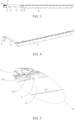
- Figure 3 shows the structural diagram of the FPC board 10 in Figure 1 , but in an unfolded configuration
- Figure 4 is the structural diagram of the FPC board 10 in Figure 1 after being folded and bent.
- the unfolded FPC board 10 is strip-shaped, including the first FPC section 11, the second FPC section 12, and the third FPC section 13 connected in sequence along the length direction of the FPC board 10, and the first FPC section 11, the second FPC section 12, and the third FPC section 13 are integrally formed.
- the strip-shaped FPC board 10 can be cut directly through the die-cutting process, avoiding the waste of FPC material.
- the length direction of the FPC board 10 in Figure 3 is exemplified as the direction from right to left.
- the first FPC section 11 is attached to the first surface of the battery module body 2
- the second FPC section 12 is attached to the second surface of the battery module body 2
- the third FPC section 13 is attached to the third surface of the battery module body 2, so that by setting the signal acquisition patch 20 at the first FPC section 11 and the signal output interface 30 at the third FPC section 13, it is possible to output the battery status signals from the third surface of the battery module body 2.
- the first surface, the second surface, and the third surface are adjacent to each other.
- the first surface is exemplified as the side surface of the battery module body 2
- the second surface is exemplified as the top surface of the battery module body 2
- the third surface is exemplified as the front surface of the battery module body 2.
- a folded portion means that the portion is bent so that at least part of it overlaps other part, that is, the bending angle is 180°; and a bent portion means that the portion is bent but does not overlap any other portion, but forming a certain angle therebetween, that is, the bending angle is less than 180°.
- the second FPC section 12 can be folded relative to the first FPC section 11 along the first dashed line 14, and then bent relative to the first FPC section 11 along the second dashed line 15, forming the relative position relationship between the second FPC section 12 and the first FPC section 11 as shown in Figure 4 , so that the second FPC section 12 is attached to the top surface of the battery module body 2.
- the third FPC section 13 is attached to the front surface of the battery module body 2.
- the third FPC section 13 can be folded relative to the second FPC section 12 along the third dashed line 16, and then bent relative to the second FPC section 12 along the fourth dashed line 17, forming the relative position relationship between the third FPC section 13 and the second FPC section 12 as shown in Figure 4 , so that the third FPC section 13 is attached to the front surface of the battery module body 2.
- the folding direction of the second FPC section 12 relative to the first FPC section 11 is inclined to the length direction of the FPC board 10, facilitating the folded second FPC section 12 to be attached to the top surface of the battery module body 2.
- the folding direction of the third FPC section 13 relative to the second FPC section 12 i.e., the third dashed line 16, which is perpendicular to the normal direction of the plane where the FPC board 10 is located
- the folding direction of the third FPC section 13 relative to the second FPC section 12 is inclined to the length direction of the FPC board 10, facilitating the folded third FPC section 13 to be attached to the front surface of the battery module body 2.
- the folding direction of the second FPC section 12 relative to the first FPC section 11 and the folding direction of the third FPC section 13 relative to the second FPC section 12 are parallel, that is, the first dashed line 14 is parallel to the third dashed line 16, facilitating the second FPC section 12 to be folded and bent from the side surface of the battery module body 2 to be attached to the top surface of the battery module body 2, and then the third FPC section 13 can also be folded and bent from the top surface of the battery module body 2 to be attached to the front surface.
- the angle between the crease along which the second FPC section 12 is to be folded relative to the first FPC section 11 and the length direction of the FPC board 10 is 45°, that is, the angle between the first dashed line 14 and the length direction of the FPC board 10 is 45°, so that after the second FPC section 12 is folded and bent from the side surface of the battery module body 2 to be attached to the top surface, the second FPC section 12 is parallel or perpendicular to the edge of the top surface of the battery module body 2, facilitating the installation of the second FPC section 12.
- the angle between the crease along which the third FPC section 13 is to be folded relative to the second FPC section 12 and the length direction of the FPC board 10 is 45°, that is, the angle between the third dashed line 16 and the length direction of the FPC board 10 is 45°, so that after the third FPC section 13 is folded and bent from the top surface of the battery module body 2 to be attached to the front surface, the second FPC section 12 is parallel or perpendicular to the edge of the front surface of the battery module body 2, facilitating the installation of the third FPC section 13.
- the crease along which the second FPC section 12 is to be bent relative to the first FPC section 11 i.e., the second dashed line 15
- the crease along which the third FPC section 13 is to be bent relative to the second FPC section 12 i.e., the fourth dashed line 17
- the crease along which the third FPC section 13 is to be bent relative to the second FPC section 12 are both perpendicular to the length direction of the FPC board 10, facilitating the attachment of the second FPC section 12 to the top surface and the third FPC section 13 to the front surface of the battery module body 2.
- the positions where the second FPC section 12 is folded relative to the first FPC section 11, and where the third FPC section 13 is folded relative to the second FPC section 12, are both equipped with foam.
- the foam is generally set between the two overlapping parts after folding operation, so as to prevent the FPC from springing back after folding.
- the second FPC section 12 and the first FPC section 11 overlap at least in part, at this time, foam can be set between the overlapping part of the second FPC section 12 and the overlapping part of the first FPC section 11.
- foam can be set between the overlapping part of the third FPC section 13 and the overlapping part of the second FPC section 12.
- the length and width of the foam can both be 1 millimeter.
- Figure 5 is the detailed structural diagram of area B in Figure 1 .
- one end of the signal acquisition patch 20 is connected to the first FPC section 11, and the other end is connected to the busbar 4 on the top surface of the battery module body 2, with batteries connected below the busbar 4, facilitating the signal acquisition patch 20 to collect battery status signals.
- the end of the signal acquisition patch 20 connected to the busbar 4 will also move upward, which can easily cause the signal acquisition patch 20 to break and affect the collection of battery status signals.
- Figure 6 is the plan view of part of the structure in the first FPC section 11 in Figure 5 .
- the groove 18 is set on the side of the first FPC section 11 facing the top surface of the battery module body 2, and the first FPC section 11 includes an "S" shaped connector 19, which is set in the groove 18, and there is a gap between the "S" shaped connector 19 and the groove 18.
- the "S" shaped connector 19 includes the first end 191 and the second end 192, with the first end 191 fixed to the first side wall 181 of the groove 18, and the signal acquisition patch 20 fixed to the second end 192.
- the "S" shaped connector 19 allows the signal acquisition patch 20 to follow the busbar 4 and move upward a certain distance, avoiding the breakage of the signal acquisition patch 20.
- the structure shown in Figure 6 can exist in multiple quantities to connect different signal acquisition patches 20 through different "S" shaped connectors 19.
- the dimensions of the "S" shaped connector 19 are illustrated, for example, Figure 6 shows the dimensions at positions C, D, E, F, G, H, which can be 6 millimeters at C, 4 millimeters at D, 10 millimeters at E, 2 millimeters at F, 8 millimeters at G, and 7.2 millimeters at H.
- the material of the first FPC section 11 is explained.
- Figure 7 shows the laminated structure in the cross-section of the first FPC section 11.
- the first FPC section 11 includes the first protective film layer 111, the FPC substrate layer 112, the cover film layer 113, and the second protective film layer 114, stacked in order, with the first protective film layer 111 located on a side of the first FPC section 11 close to the battery module body 2, and the second protective film layer 114 located on a side of the first FPC section 11 away from the battery module body 2.
- One end of the signal acquisition patch 20 is fixed between the FPC substrate layer 112 and the cover film layer 113 at the second end 192, allowing the signal acquisition patch 20 to make contact with the FPC substrate layer 112, so that the battery status signals collected by the signal acquisition patch 20 can be transmitted from the signal acquisition patch 20 to the FPC substrate layer 112 for transmission within the FPC substrate layer 112.
- the FPC substrate layer 112 specifically includes the PI (Polyimide Film) reinforcement layer, the substrate adhesive layer, and the FPC copper foil, stacked in order, with the PI reinforcement layer set on a side of the FPC substrate layer 112 away from the cover film layer 113, and the FPC copper foil set on a side of the FPC substrate layer 112 close to the cover film layer 113.
- the end of the signal acquisition patch 20 fixed between the FPC substrate layer 112 and the cover film layer 113 is specifically fixed between the FPC copper foil and the cover film layer 113, and the fixation of this end of the signal acquisition patch 20 can be achieved using solder paste and reflow soldering.
- the thickness of the FPC substrate layer 112 can be 0.11 millimeters, where the thickness of the FPC copper foil is 35 micrometers, the thickness of the substrate adhesive layer is 25 micrometers, and the thickness of the PI reinforcement layer is 50 micrometers.
- the thicknesses of the first protective film layer 111 and of the second protective film layer 114 are both 50 micrometers, the thickness of the adhesive between the first protective film layer 111 and the PI reinforcement layer, the thickness of the adhesive between the second protective film layer 114 and the PI reinforcement layer, and the thickness of the adhesive between the cover film layer 113 and the FPC copper foil are 25 micrometers each, resulting in the total thickness of the first FPC section 11 of 0.3 ⁇ 0.05 millimeters.
- the second end 192 is connected to the second side wall 182 of the groove 18 via the micro-connection section 193, with the second side wall 182 and the first side wall 181 set opposite to each other.
- the micro-connection section 193 the wobbling of the "S" shaped connector 19 is avoided, allowing the second protective film layer 114 to adhere accurately, thereby increasing the yield and production efficiency of the FPC.
- the width of the micro-connection section 193 in the direction perpendicular to the top surface of the battery module body 2 can be 1 millimeter, thus achieving micro-connection.
- the positioning hole 183 is set on the side of the groove 18 away from the "S" shaped connector 19.
- the positioning hole 183 successively penetrates the first protective film layer 111, the FPC substrate layer 112, the cover film layer 113, and the second protective film layer 114.
- the positioning hole 183 is configured to allow the positioning column 3 on the battery module body to pass through.
- the positioning column 3 can also pass through the second protective film layer 114 via the positioning hole 183, facilitating the simultaneous positioning the first protective film layer 111, the FPC substrate layer 112, the cover film layer 113, and the second protective film layer 114 by the positioning column 3, further reducing the difficulty of accurately adhering the second protective film layer 114.
- Figure 8 is another detailed structural diagram of area B in Figure 1 .
- the signal acquisition patch 20 includes the first signal acquisition segment 21 and the second signal acquisition segment 22, connected in sequence along the length direction of the signal acquisition patch 20, and integrated into one piece.
- the first signal acquisition segment 21 is set on a side of the battery module body 2 where the first FPC section 11 is located, and an end of the first signal acquisition segment 21 away from the second signal acquisition segment 22 is fixed to the second end 192.
- the second signal acquisition segment 22 is attached to the top surface of the battery module body 2, with an end of the second signal acquisition segment 22 away from the first signal acquisition segment 21 fixed to the busbar 4 on the top surface.
- the signal acquisition patch 20 can collect battery status signals from the busbar 4 on the top surface of the battery module body 2 and transmit them to the first FPC section 11 on the side of the battery module body 2.
- the distance between the crease 23 along which the second signal acquisition segment 22 is to be bent relative to the first signal acquisition segment 21 and the second end 192 is greater than or equal to a preset distance, thus reserving a certain space between this crease and the second end 192.
- the bending jig can use the space between the crease and the second end 192 to perform the bending operation, avoiding pressing on the first FPC section 11 and affecting the collection of battery status signals.
- the value of the preset distance is set based on the space required for the bending jig to perform the bending operation, for example, the preset distance can be 2 millimeters.
- the battery module includes the battery module body 2, as well as the FPC acquisition device 1 as described in any of the above.
- the battery module body 2 includes the batteries, the busbars 4, and the positioning columns 3.
- the FPC acquisition device 1 is configured to collect battery status signals in the battery module body 2, achieving the output of battery status signals on the front surface of the battery module body 2 while reducing the material cost of making the FPC board 10.
Landscapes
- Chemical & Material Sciences (AREA)
- Chemical Kinetics & Catalysis (AREA)
- Electrochemistry (AREA)
- General Chemical & Material Sciences (AREA)
- Engineering & Computer Science (AREA)
- Manufacturing & Machinery (AREA)
- Microelectronics & Electronic Packaging (AREA)
- Battery Mounting, Suspending (AREA)
- Structure Of Printed Boards (AREA)
Abstract
This application provides an FPC acquisition device and a battery module, including: a first FPC section, a second FPC section, and a third FPC section, where the first FPC section is attached to a first surface of the battery module body, the second FPC section is, attached to a second surface of the battery module body after being folded and bent relative to the first FPC section, and the third FPC section is attached to a third surface of the battery module body after being folded and bent relative to the second FPC section.
Description
- This application relates to the field of battery technology, specifically to an FPC (Flexible Printed Circuit) acquisition device and a battery module.
- In the related technology, the FPC board in most battery modules is disposed on a side of the battery module body. By bending a section of the FPC board 90° to a top surface of the battery module body, and then bending a part of the FPC section on the top surface 90° to a front surface of the battery module body, signals collected by the FPC board are allowed to output from the front surface of the battery module body.
- However, a planar shape of the FPC board mentioned in the background is generally "Z" shaped. In the production of such FPC board, it is necessary to cut a large area of FPC material without wiring through the die-cutting process, which leads to a waste of FPC material and thus increases a material cost of making the FPC board.
- This application provides an FPC acquisition device. The FPC acquisition device includes:
- an FPC board, strip-shaped, comprising a first FPC section, a second FPC section, and a third FPC section connected in sequence along a length direction of the FPC board, wherein the first FPC section, the second FPC section, and the third FPC section are integrally formed; the first FPC section is attached to a first surface of a battery module body; the second FPC section is, after being folded and bent relative to the first FPC section, attached to a second surface of the battery module body; the third FPC section is, after being folded and bent relative to the second FPC section, attached to a third surface of the battery module body; and the first surface, the second surface, and the third surface are adjacent to each other;
- a signal acquisition patch, disposed at the first FPC section;
- a signal output interface, disposed at the third FPC section.
- This application also provides a battery module. The battery module includes a battery module body and the FPC acquisition device according to any one of the aforementioned, where the FPC acquisition device is configured to collect battery status signals in the battery module body.
- In this application, a strip-shaped FPC board is used, divided into three FPC sections. Through folding and bending between the FPC sections, one of the FPC sections is attached to other adjacent surface of the battery module body, ultimately allowing the signals collected by the FPC board to be output from the third FPC section attached to the third surface of the battery module body. This eliminates the need for a "Z" shaped FPC board, resulting in less material waste and reduced material costs for making the FPC board compared to the "Z" shaped FPC board.
-
-
Figure 1 is a schematic diagram of the overall structure of the FPC acquisition device and the battery module body provided by a possible implementation of this application; -
Figure 2 is a detailed structural diagram of area A inFigure 1 ; -
Figure 3 shows the structural diagram of the FPC board inFigure 1 , but in an unfolded configuration; -
Figure 4 is a structural diagram of the folded and bent FPC board inFigure 1 ; -
Figure 5 is a detailed structural diagram of area B inFigure 1 ; -
Figure 6 is a plan view of part of the structure in the first FPC section inFigure 5 ; -
Figure 7 is a diagram showing the laminated structure in the cross-section of the first FPC section; -
Figure 8 is another detailed structural diagram of area B inFigure 1 . - 1: FPC acquisition device; 10: FPC board; 11: First FPC section; 12: Second FPC section; 13: Third FPC section; 14: First dashed line; 15: Second dashed line; 16: Third dashed line; 17: Fourth dashed line; 18: Groove; 181: First side wall; 182: Second side wall; 183: Positioning hole; 19: "S" shaped connector; 191: First end; 192: Second end; 193: Micro-connection section; 111: First protective film layer; 112: FPC substrate layer; 113: Cover film layer; 114: Second protective film layer; 20: Signal acquisition patch; 21: First signal acquisition segment; 22: Second signal acquisition segment; 23: Crease along which the second
signal acquisition segment 22 is to be bent relative to the firstsignal acquisition segment 21; 30: Signal output interface; 2: Battery module body; 3: Positioning column; 4: Busbar. - In this application, without contrary indication, directional terms such as "top" and "bottom" usually refer to the top and bottom in the actual use or working state of the device, specifically the direction in the drawings; while "inner" and "outer" are in relation to the outline of the device.
- In order to reduce the material cost of making the FPC board, the possible implementation of this application provides the FPC acquisition device and the battery module, using the strip-shaped FPC board, divided into three FPC sections; through folding and bending between the FPC sections, one of the FPC sections is attached to other adjacent surface of the battery module body, the implementation ultimately allows the signals collected by the FPC board to be output from the third FPC section attached to the third surface of the battery module body. This eliminates the need for the "Z" shaped FPC board, resulting in less material waste and reduced material costs for making the FPC board, and no additional cutting processes are needed, reducing the processing cycle of the FPC board. For specific solutions, please refer to the following detailed description.
- In a first aspect, the possible implementation of this application provides an FPC acquisition device. Please refer to
Figures 1 and 2, Figure 1 is the schematic diagram of the overall structure of theFPC acquisition device 1 and thebattery module body 2, andFigure 2 is the detailed structural diagram of area A inFigure 1 . It can be seen fromFigures 1 and 2 that theFPC acquisition device 1 includes thesignal acquisition patches 20, theFPC board 10, and thesignal output interface 30. Thesignal acquisition patches 20 each are generally a nickel patch. Eachsignal acquisition patch 20 is used to collect battery status signals of a row of batteries connected by a corresponding busbar in thebattery module body 2, and the battery status signals generally record signals such as the current voltage and temperature of the battery. TheFPC board 10 is used to transmit the battery status signals collected by thesignal acquisition patches 20 to thesignal output interface 30, so that the battery status signals can be output externally from thesignal output interface 30. For example, thesignal output interface 30 can be connected to the BMS (Battery Management System) outside the battery module, facilitating the monitoring and management of the batteries status in thebattery module body 2 by the BMS. Thebattery module body 2 contains batteries that provide electrical energy, for example, to electric vehicles. - Please refer to
Figures 3 and 4, Figure 3 shows the structural diagram of theFPC board 10 inFigure 1 , but in an unfolded configuration, andFigure 4 is the structural diagram of theFPC board 10 inFigure 1 after being folded and bent. It can be seen fromFigure 3 that theunfolded FPC board 10 is strip-shaped, including thefirst FPC section 11, thesecond FPC section 12, and thethird FPC section 13 connected in sequence along the length direction of theFPC board 10, and thefirst FPC section 11, thesecond FPC section 12, and thethird FPC section 13 are integrally formed. Thus, the strip-shaped FPC board 10 can be cut directly through the die-cutting process, avoiding the waste of FPC material. The length direction of theFPC board 10 inFigure 3 is exemplified as the direction from right to left. - Refer to
Figures 2 and4 , thefirst FPC section 11 is attached to the first surface of thebattery module body 2, thesecond FPC section 12 is attached to the second surface of thebattery module body 2, and thethird FPC section 13 is attached to the third surface of thebattery module body 2, so that by setting thesignal acquisition patch 20 at thefirst FPC section 11 and thesignal output interface 30 at thethird FPC section 13, it is possible to output the battery status signals from the third surface of thebattery module body 2. The first surface, the second surface, and the third surface are adjacent to each other. InFigure 2 , the first surface is exemplified as the side surface of thebattery module body 2, the second surface is exemplified as the top surface of thebattery module body 2, and the third surface is exemplified as the front surface of thebattery module body 2. To more specifically describe the FPC acquisition device in the possible implementation of this application. The following content is described using the side surface, the top surface, and the front surface of thebattery module body 2 shown inFigure 2 , instead of the first surface, the second surface, and the third surface, as follows. - Refer to
Figures 3 and 4 , after thesecond FPC section 12 is folded and bent relative to thefirst FPC section 11, and thesecond FPC section 12 is attached to the top surface of thebattery module body 2. In this case, a folded portion means that the portion is bent so that at least part of it overlaps other part, that is, the bending angle is 180°; and a bent portion means that the portion is bent but does not overlap any other portion, but forming a certain angle therebetween, that is, the bending angle is less than 180°. InFigure 3 , since thefirst FPC section 11 is attached to the side surface of thebattery module body 2, thesecond FPC section 12 can be folded relative to thefirst FPC section 11 along the first dashedline 14, and then bent relative to thefirst FPC section 11 along the second dashedline 15, forming the relative position relationship between thesecond FPC section 12 and thefirst FPC section 11 as shown inFigure 4 , so that thesecond FPC section 12 is attached to the top surface of thebattery module body 2. - Similarly, after the
third FPC section 13 is folded and bent relative to thesecond FPC section 12, thethird FPC section 13 is attached to the front surface of thebattery module body 2. Specifically, inFigure 3 , after thesecond FPC section 12 is attached to the top surface of thebattery module body 2, thethird FPC section 13 can be folded relative to thesecond FPC section 12 along the third dashedline 16, and then bent relative to thesecond FPC section 12 along the fourth dashedline 17, forming the relative position relationship between thethird FPC section 13 and thesecond FPC section 12 as shown inFigure 4 , so that thethird FPC section 13 is attached to the front surface of thebattery module body 2. - In some possible implementations of this application, in
Figure 3 , the folding direction of thesecond FPC section 12 relative to the first FPC section 11 (i.e., the first dashedline 14, which is perpendicular to the normal direction of the plane where theFPC board 10 is located) is inclined to the length direction of theFPC board 10, facilitating the foldedsecond FPC section 12 to be attached to the top surface of thebattery module body 2. Similarly, inFigure 3 , the folding direction of thethird FPC section 13 relative to the second FPC section 12 (i.e., the third dashedline 16, which is perpendicular to the normal direction of the plane where theFPC board 10 is located) is inclined to the length direction of theFPC board 10, facilitating the foldedthird FPC section 13 to be attached to the front surface of thebattery module body 2. - In some possible implementations of this application, in
Figure 3 , the folding direction of thesecond FPC section 12 relative to thefirst FPC section 11 and the folding direction of thethird FPC section 13 relative to thesecond FPC section 12 are parallel, that is, the first dashedline 14 is parallel to the third dashedline 16, facilitating thesecond FPC section 12 to be folded and bent from the side surface of thebattery module body 2 to be attached to the top surface of thebattery module body 2, and then thethird FPC section 13 can also be folded and bent from the top surface of thebattery module body 2 to be attached to the front surface. - In some possible implementations of this application, in
Figure 3 , the angle between the crease along which thesecond FPC section 12 is to be folded relative to thefirst FPC section 11 and the length direction of theFPC board 10 is 45°, that is, the angle between the firstdashed line 14 and the length direction of theFPC board 10 is 45°, so that after thesecond FPC section 12 is folded and bent from the side surface of thebattery module body 2 to be attached to the top surface, thesecond FPC section 12 is parallel or perpendicular to the edge of the top surface of thebattery module body 2, facilitating the installation of thesecond FPC section 12. Similarly, inFigure 3 , the angle between the crease along which thethird FPC section 13 is to be folded relative to thesecond FPC section 12 and the length direction of theFPC board 10 is 45°, that is, the angle between the third dashedline 16 and the length direction of theFPC board 10 is 45°, so that after thethird FPC section 13 is folded and bent from the top surface of thebattery module body 2 to be attached to the front surface, thesecond FPC section 12 is parallel or perpendicular to the edge of the front surface of thebattery module body 2, facilitating the installation of thethird FPC section 13. - In some possible implementations of this application, in
Figure 3 , the crease along which thesecond FPC section 12 is to be bent relative to the first FPC section 11 (i.e., the second dashed line 15), and the crease along which thethird FPC section 13 is to be bent relative to the second FPC section 12 (i.e., the fourth dashed line 17) are both perpendicular to the length direction of theFPC board 10, facilitating the attachment of thesecond FPC section 12 to the top surface and thethird FPC section 13 to the front surface of thebattery module body 2. - In some possible implementations of this application, the positions where the
second FPC section 12 is folded relative to thefirst FPC section 11, and where thethird FPC section 13 is folded relative to thesecond FPC section 12, are both equipped with foam. Specifically, the foam is generally set between the two overlapping parts after folding operation, so as to prevent the FPC from springing back after folding. For example, after thesecond FPC section 12 is folded relative to thefirst FPC section 11, thesecond FPC section 12 and thefirst FPC section 11 overlap at least in part, at this time, foam can be set between the overlapping part of thesecond FPC section 12 and the overlapping part of thefirst FPC section 11. Similarly, after thethird FPC section 13 is folded relative to thesecond FPC section 12, thethird FPC section 13 and thesecond FPC section 12 overlap at least in part, at this time, foam can be set between the overlapping part of thethird FPC section 13 and the overlapping part of thesecond FPC section 12. In an example, the length and width of the foam can both be 1 millimeter. - In some possible implementations of this application, as shown in
Figure 5, Figure 5 is the detailed structural diagram of area B inFigure 1 . InFigure 5 , one end of thesignal acquisition patch 20 is connected to thefirst FPC section 11, and the other end is connected to thebusbar 4 on the top surface of thebattery module body 2, with batteries connected below thebusbar 4, facilitating thesignal acquisition patch 20 to collect battery status signals. However, when some battery expands upward due to heat or other factors, the end of thesignal acquisition patch 20 connected to thebusbar 4 will also move upward, which can easily cause thesignal acquisition patch 20 to break and affect the collection of battery status signals. - To address this, some possible implementations of this application have made improvements to part of the structure in the
first FPC section 11. Specifically, as shown inFigure 6, Figure 6 is the plan view of part of the structure in thefirst FPC section 11 inFigure 5 . InFigure 6 , thegroove 18 is set on the side of thefirst FPC section 11 facing the top surface of thebattery module body 2, and thefirst FPC section 11 includes an "S" shapedconnector 19, which is set in thegroove 18, and there is a gap between the "S" shapedconnector 19 and thegroove 18. The "S" shapedconnector 19 includes thefirst end 191 and thesecond end 192, with thefirst end 191 fixed to thefirst side wall 181 of thegroove 18, and thesignal acquisition patch 20 fixed to thesecond end 192. In this way, even if the battery expands upward, the "S" shapedconnector 19 allows thesignal acquisition patch 20 to follow thebusbar 4 and move upward a certain distance, avoiding the breakage of thesignal acquisition patch 20. The structure shown inFigure 6 can exist in multiple quantities to connect differentsignal acquisition patches 20 through different "S" shapedconnectors 19. - In an example, the dimensions of the "S" shaped
connector 19 are illustrated, for example,Figure 6 shows the dimensions at positions C, D, E, F, G, H, which can be 6 millimeters at C, 4 millimeters at D, 10 millimeters at E, 2 millimeters at F, 8 millimeters at G, and 7.2 millimeters at H. - In some possible implementations of this application, the material of the
first FPC section 11 is explained. Refer toFigure 7, Figure 7 shows the laminated structure in the cross-section of thefirst FPC section 11. InFigure 7 , thefirst FPC section 11 includes the firstprotective film layer 111, theFPC substrate layer 112, thecover film layer 113, and the secondprotective film layer 114, stacked in order, with the firstprotective film layer 111 located on a side of thefirst FPC section 11 close to thebattery module body 2, and the secondprotective film layer 114 located on a side of thefirst FPC section 11 away from thebattery module body 2. One end of thesignal acquisition patch 20 is fixed between theFPC substrate layer 112 and thecover film layer 113 at thesecond end 192, allowing thesignal acquisition patch 20 to make contact with theFPC substrate layer 112, so that the battery status signals collected by thesignal acquisition patch 20 can be transmitted from thesignal acquisition patch 20 to theFPC substrate layer 112 for transmission within theFPC substrate layer 112. - The
FPC substrate layer 112 specifically includes the PI (Polyimide Film) reinforcement layer, the substrate adhesive layer, and the FPC copper foil, stacked in order, with the PI reinforcement layer set on a side of theFPC substrate layer 112 away from thecover film layer 113, and the FPC copper foil set on a side of theFPC substrate layer 112 close to thecover film layer 113. The end of thesignal acquisition patch 20 fixed between theFPC substrate layer 112 and thecover film layer 113 is specifically fixed between the FPC copper foil and thecover film layer 113, and the fixation of this end of thesignal acquisition patch 20 can be achieved using solder paste and reflow soldering. - In an example, the thickness of the
FPC substrate layer 112 can be 0.11 millimeters, where the thickness of the FPC copper foil is 35 micrometers, the thickness of the substrate adhesive layer is 25 micrometers, and the thickness of the PI reinforcement layer is 50 micrometers. The thicknesses of the firstprotective film layer 111 and of the secondprotective film layer 114 are both 50 micrometers, the thickness of the adhesive between the firstprotective film layer 111 and the PI reinforcement layer, the thickness of the adhesive between the secondprotective film layer 114 and the PI reinforcement layer, and the thickness of the adhesive between thecover film layer 113 and the FPC copper foil are 25 micrometers each, resulting in the total thickness of thefirst FPC section 11 of 0.3 ± 0.05 millimeters. - In the process of forming the
first FPC section 11, after welding one end of thesignal acquisition patch 20 to theFPC substrate layer 112 and covering it with thecover film layer 113, it is also necessary to adhere the secondprotective film layer 114 on top of thecover film layer 113. However, due to the structural design of the "S" shapedconnector 19, the "S" shapedconnector 19 may wobble, making it difficult for the secondprotective film layer 114 to adhere accurately. - To address this, some possible implementations of this application have further improved part of the structure in the
first FPC section 11. Specifically, as shown inFigure 6 , thesecond end 192 is connected to thesecond side wall 182 of thegroove 18 via themicro-connection section 193, with thesecond side wall 182 and thefirst side wall 181 set opposite to each other. Under the constraint of themicro-connection section 193, the wobbling of the "S" shapedconnector 19 is avoided, allowing the secondprotective film layer 114 to adhere accurately, thereby increasing the yield and production efficiency of the FPC. In an example, the width of themicro-connection section 193 in the direction perpendicular to the top surface of thebattery module body 2 can be 1 millimeter, thus achieving micro-connection. - In some possible implementations of this application, as shown in
Figure 6 , thepositioning hole 183 is set on the side of thegroove 18 away from the "S" shapedconnector 19. Thepositioning hole 183 successively penetrates the firstprotective film layer 111, theFPC substrate layer 112, thecover film layer 113, and the secondprotective film layer 114. Thepositioning hole 183 is configured to allow thepositioning column 3 on the battery module body to pass through. In this way, when the secondprotective film layer 114 is adhered to the "S" shapedconnector 19, thepositioning column 3 can also pass through the secondprotective film layer 114 via thepositioning hole 183, facilitating the simultaneous positioning the firstprotective film layer 111, theFPC substrate layer 112, thecover film layer 113, and the secondprotective film layer 114 by thepositioning column 3, further reducing the difficulty of accurately adhering the secondprotective film layer 114. - In some possible implementations of this application, as shown in
Figure 8, Figure 8 is another detailed structural diagram of area B inFigure 1 . InFigure 8 , thesignal acquisition patch 20 includes the firstsignal acquisition segment 21 and the secondsignal acquisition segment 22, connected in sequence along the length direction of thesignal acquisition patch 20, and integrated into one piece. The firstsignal acquisition segment 21 is set on a side of thebattery module body 2 where thefirst FPC section 11 is located, and an end of the firstsignal acquisition segment 21 away from the secondsignal acquisition segment 22 is fixed to thesecond end 192. After being bent relative to the firstsignal acquisition segment 21, the secondsignal acquisition segment 22 is attached to the top surface of thebattery module body 2, with an end of the secondsignal acquisition segment 22 away from the firstsignal acquisition segment 21 fixed to thebusbar 4 on the top surface. In this way, thesignal acquisition patch 20 can collect battery status signals from thebusbar 4 on the top surface of thebattery module body 2 and transmit them to thefirst FPC section 11 on the side of thebattery module body 2. - In some possible implementations of this application, the distance between the
crease 23 along which the secondsignal acquisition segment 22 is to be bent relative to the firstsignal acquisition segment 21 and thesecond end 192 is greater than or equal to a preset distance, thus reserving a certain space between this crease and thesecond end 192. In this way, when bending the secondsignal acquisition segment 22 with a bending jig, the bending jig can use the space between the crease and thesecond end 192 to perform the bending operation, avoiding pressing on thefirst FPC section 11 and affecting the collection of battery status signals. The value of the preset distance is set based on the space required for the bending jig to perform the bending operation, for example, the preset distance can be 2 millimeters. - In a second aspect, some possible implementations of this application provide a battery module. The battery module includes the
battery module body 2, as well as theFPC acquisition device 1 as described in any of the above. Thebattery module body 2 includes the batteries, thebusbars 4, and thepositioning columns 3. TheFPC acquisition device 1 is configured to collect battery status signals in thebattery module body 2, achieving the output of battery status signals on the front surface of thebattery module body 2 while reducing the material cost of making theFPC board 10.
Claims (10)
- An FPC acquisition device (1), characterized in that:an FPC board (10), strip-shaped, comprising a first FPC section (11), a second FPC section (12), and a third FPC section (13) connected in sequence along a length direction of the FPC board (10), wherein the first FPC section (11), the second FPC section (12), and the third FPC section (13) are integrally formed; the first FPC section (11) is attached to a first surface of a battery module body (2); the second FPC section (12) is, after being folded and bent relative to the first FPC section (11), attached to a second surface of the battery module body (2); the third FPC section (13) is, after being folded and bent relative to the second FPC section (12), attached to a third surface of the battery module body (2); and the first surface, the second surface, and the third surface are adjacent to each other;a signal acquisition patch (20) disposed at the first FPC section (11); anda signal output interface (30) disposed at the third FPC section (13).
- The FPC acquisition device (1) according to claim 1, characterized in that a folding direction of the second FPC section (12) relative to the first FPC section (11) is inclined to the length direction of the FPC board (10), and a folding direction of the third FPC section (13) relative to the second FPC section (12) is inclined to the length direction of the FPC board (10).
- The FPC acquisition device (1) according to claim 2, characterized in that an angle between a direction of a crease along which the second FPC section (12) is folded relative to the first FPC section (11) and the length direction of the FPC board (10) is 45°, and an angle between a direction of a crease along which the third FPC section (13) is folded relative to the second FPC section (12) and the length direction of the FPC board (10) is 45°.
- The FPC acquisition device (1) according to claim 1, characterized in that a groove (18) is provided on a side of the first FPC section (11) facing the second surface, the first FPC section (11) comprises an "S" shaped connector (19), the "S" shaped connector (19) is disposed in the groove (18), the "S" shaped connector (19) comprises a first end (191) and a second end (192), the first end (191) is fixed to a first side wall (181) of the groove (18), and the signal acquisition patch (20) is fixed to the second end (192).
- The FPC acquisition device (1) according to claim 4, characterized in that a cross-section of the first FPC section (11) comprises a first protective film layer (111), an FPC substrate layer (112), a cover film layer (113), and a second protective film layer (114) stacked in order, the first protective film layer (111) is disposed on a side of the first FPC section (11) close to the battery module body (2), and one end of the signal acquisition patch (20) is fixed between the FPC substrate layer (112) and the cover film layer (113) at the second end (192).
- The FPC acquisition device (1) according to claim 5, characterized in that the second end (192) is connected to a second side wall (182) of the groove (18) via a micro-connection section (193), the second side wall (182) and the first side wall (181) are opposite to each other.
- The FPC acquisition device (1) according to claim 5, characterized in that a positioning hole (183) is provided on a side of the groove (18) away from the "S" shaped connector (19), the positioning hole (183) successively penetrates the first protective film layer (111), the FPC substrate layer (112), the cover film layer (113), and the second protective film layer (114), and is configured to allow a positioning column (3) on the battery module body (2) to pass through.
- The FPC acquisition device (1) according to claim 4, characterized in that the signal acquisition patch (20) comprises a first signal acquisition segment (21) and a second signal acquisition segment (22), the first signal acquisition segment (21) and the second signal acquisition segment (22) are connected in sequence along a length direction of the signal acquisition patch (20), the first signal acquisition segment (21) is disposed on the first surface, and an end of the first signal acquisition segment (21) away from the second signal acquisition segment (22) is fixed to the second end (192); the second signal acquisition segment (22) is, after being bent relative to the first signal acquisition segment (21), attached to the second surface; and an end of the second signal acquisition segment (22) away from the first signal acquisition segment (21) is fixed to a busbar (4) on the second surface.
- The FPC acquisition device (1) according to claim 8, characterized in that a distance between a crease (23) along which the second signal acquisition segment (22) is bent relative to the first signal acquisition segment (21) and the second end (192) is greater than or equal to a preset distance.
- A battery module, characterized in that a battery module body (2), and the FPC acquisition device (1) according to any of claims 1 to 9, the FPC acquisition device (1) is configured to collect battery status signals in the battery module body (2).
Applications Claiming Priority (2)
| Application Number | Priority Date | Filing Date | Title |
|---|---|---|---|
| CN202322306839.5U CN220628165U (en) | 2023-08-25 | 2023-08-25 | FPC collection system and battery module |
| PCT/CN2024/111748 WO2025044754A1 (en) | 2023-08-25 | 2024-08-13 | Collection device based on fpc, and battery module |
Publications (1)
| Publication Number | Publication Date |
|---|---|
| EP4525135A1 true EP4525135A1 (en) | 2025-03-19 |
Family
ID=92538856
Family Applications (1)
| Application Number | Title | Priority Date | Filing Date |
|---|---|---|---|
| EP24196215.8A Pending EP4525135A1 (en) | 2023-08-25 | 2024-08-23 | Fpc acquisition device and battery module |
Country Status (1)
| Country | Link |
|---|---|
| EP (1) | EP4525135A1 (en) |
Citations (2)
| Publication number | Priority date | Publication date | Assignee | Title |
|---|---|---|---|---|
| CN216905446U (en) * | 2022-03-15 | 2022-07-05 | 华鼎国联动力电池有限公司 | Bending type FPC (Flexible printed Circuit) acquisition device of power battery module |
| US20220407196A1 (en) * | 2020-07-22 | 2022-12-22 | Lg Energy Solution, Ltd. | Battery Module in Which Connection Between Electrode Lead and Voltage Sensing Member is Simplified, and Battery Pack Including the Same |
-
2024
- 2024-08-23 EP EP24196215.8A patent/EP4525135A1/en active Pending
Patent Citations (2)
| Publication number | Priority date | Publication date | Assignee | Title |
|---|---|---|---|---|
| US20220407196A1 (en) * | 2020-07-22 | 2022-12-22 | Lg Energy Solution, Ltd. | Battery Module in Which Connection Between Electrode Lead and Voltage Sensing Member is Simplified, and Battery Pack Including the Same |
| CN216905446U (en) * | 2022-03-15 | 2022-07-05 | 华鼎国联动力电池有限公司 | Bending type FPC (Flexible printed Circuit) acquisition device of power battery module |
Similar Documents
| Publication | Publication Date | Title |
|---|---|---|
| JP6257889B2 (en) | Flexible printed wiring board with bus bar, manufacturing method thereof, and battery system | |
| US11563240B2 (en) | Sampling circuit board for battery module and battery module | |
| EP1157892A1 (en) | Wire harness joint | |
| EP3063824B1 (en) | Signal collection assembly and power battery module comprising the same | |
| CN115579588A (en) | An FFC-FPC combined battery module integrated acquisition busbar | |
| KR102187081B1 (en) | Printed circuit board | |
| EP2410577B1 (en) | Connection for photovoltaic module | |
| CN117335100A (en) | CCS components and battery modules | |
| CN220628165U (en) | FPC collection system and battery module | |
| JP6258437B2 (en) | Manufacturing method of flexible printed wiring board with bus bar | |
| CN212161961U (en) | Signal transmission terminal, sampling device, battery module and device | |
| CN211240287U (en) | FPC acquisition module of power battery | |
| CN220873786U (en) | Integrated busbar structure and battery module | |
| CN112582690A (en) | Flexible circuit board, die-cut substrate, and battery device | |
| CN220358287U (en) | Battery sampling device, battery module and battery system | |
| CN219959355U (en) | CCS acquisition structure and battery module | |
| CN218939950U (en) | FFC-FPC combined battery module integrated acquisition busbar | |
| EP2432032A2 (en) | Solar cell module and laminating method | |
| CN215379329U (en) | Flexible circuit board and power battery pack | |
| CN210629978U (en) | Flexible circuit board for collecting cell information | |
| CN112584602A (en) | Flexible circuit board, battery device, and method for assembling battery device | |
| CN223785165U (en) | Battery pack and power battery system | |
| CN219739244U (en) | Battery device | |
| CN112542659A (en) | Connecting module for power battery and production process | |
| CN215600430U (en) | Collection components, battery modules and carrying components |
Legal Events
| Date | Code | Title | Description |
|---|---|---|---|
| PUAI | Public reference made under article 153(3) epc to a published international application that has entered the european phase |
Free format text: ORIGINAL CODE: 0009012 |
|
| STAA | Information on the status of an ep patent application or granted ep patent |
Free format text: STATUS: REQUEST FOR EXAMINATION WAS MADE |
|
| 17P | Request for examination filed |
Effective date: 20240823 |
|
| AK | Designated contracting states |
Kind code of ref document: A1 Designated state(s): AL AT BE BG CH CY CZ DE DK EE ES FI FR GB GR HR HU IE IS IT LI LT LU LV MC ME MK MT NL NO PL PT RO RS SE SI SK SM TR |