EP4525113A2 - Wiederaufladbare batterie - Google Patents
Wiederaufladbare batterie Download PDFInfo
- Publication number
- EP4525113A2 EP4525113A2 EP24199700.6A EP24199700A EP4525113A2 EP 4525113 A2 EP4525113 A2 EP 4525113A2 EP 24199700 A EP24199700 A EP 24199700A EP 4525113 A2 EP4525113 A2 EP 4525113A2
- Authority
- EP
- European Patent Office
- Prior art keywords
- electrode assembly
- rechargeable battery
- electrode
- bonding part
- length direction
- Prior art date
- Legal status (The legal status is an assumption and is not a legal conclusion. Google has not performed a legal analysis and makes no representation as to the accuracy of the status listed.)
- Pending
Links
Images





Classifications
-
- H—ELECTRICITY
- H01—ELECTRIC ELEMENTS
- H01M—PROCESSES OR MEANS, e.g. BATTERIES, FOR THE DIRECT CONVERSION OF CHEMICAL ENERGY INTO ELECTRICAL ENERGY
- H01M50/00—Constructional details or processes of manufacture of the non-active parts of electrochemical cells other than fuel cells, e.g. hybrid cells
- H01M50/40—Separators; Membranes; Diaphragms; Spacing elements inside cells
- H01M50/46—Separators, membranes or diaphragms characterised by their combination with electrodes
- H01M50/461—Separators, membranes or diaphragms characterised by their combination with electrodes with adhesive layers between electrodes and separators
-
- H—ELECTRICITY
- H01—ELECTRIC ELEMENTS
- H01M—PROCESSES OR MEANS, e.g. BATTERIES, FOR THE DIRECT CONVERSION OF CHEMICAL ENERGY INTO ELECTRICAL ENERGY
- H01M50/00—Constructional details or processes of manufacture of the non-active parts of electrochemical cells other than fuel cells, e.g. hybrid cells
- H01M50/50—Current conducting connections for cells or batteries
- H01M50/531—Electrode connections inside a battery casing
-
- H—ELECTRICITY
- H01—ELECTRIC ELEMENTS
- H01M—PROCESSES OR MEANS, e.g. BATTERIES, FOR THE DIRECT CONVERSION OF CHEMICAL ENERGY INTO ELECTRICAL ENERGY
- H01M10/00—Secondary cells; Manufacture thereof
- H01M10/04—Construction or manufacture in general
- H01M10/0481—Compression means other than compression means for stacks of electrodes and separators
-
- H—ELECTRICITY
- H01—ELECTRIC ELEMENTS
- H01M—PROCESSES OR MEANS, e.g. BATTERIES, FOR THE DIRECT CONVERSION OF CHEMICAL ENERGY INTO ELECTRICAL ENERGY
- H01M10/00—Secondary cells; Manufacture thereof
- H01M10/04—Construction or manufacture in general
- H01M10/0431—Cells with wound or folded electrodes
-
- H—ELECTRICITY
- H01—ELECTRIC ELEMENTS
- H01M—PROCESSES OR MEANS, e.g. BATTERIES, FOR THE DIRECT CONVERSION OF CHEMICAL ENERGY INTO ELECTRICAL ENERGY
- H01M10/00—Secondary cells; Manufacture thereof
- H01M10/04—Construction or manufacture in general
- H01M10/0463—Cells or batteries with horizontal or inclined electrodes
-
- H—ELECTRICITY
- H01—ELECTRIC ELEMENTS
- H01M—PROCESSES OR MEANS, e.g. BATTERIES, FOR THE DIRECT CONVERSION OF CHEMICAL ENERGY INTO ELECTRICAL ENERGY
- H01M10/00—Secondary cells; Manufacture thereof
- H01M10/05—Accumulators with non-aqueous electrolyte
- H01M10/058—Construction or manufacture
- H01M10/0585—Construction or manufacture of accumulators having only flat construction elements, i.e. flat positive electrodes, flat negative electrodes and flat separators
-
- H—ELECTRICITY
- H01—ELECTRIC ELEMENTS
- H01M—PROCESSES OR MEANS, e.g. BATTERIES, FOR THE DIRECT CONVERSION OF CHEMICAL ENERGY INTO ELECTRICAL ENERGY
- H01M10/00—Secondary cells; Manufacture thereof
- H01M10/05—Accumulators with non-aqueous electrolyte
- H01M10/058—Construction or manufacture
- H01M10/0587—Construction or manufacture of accumulators having only wound construction elements, i.e. wound positive electrodes, wound negative electrodes and wound separators
-
- H—ELECTRICITY
- H01—ELECTRIC ELEMENTS
- H01M—PROCESSES OR MEANS, e.g. BATTERIES, FOR THE DIRECT CONVERSION OF CHEMICAL ENERGY INTO ELECTRICAL ENERGY
- H01M50/00—Constructional details or processes of manufacture of the non-active parts of electrochemical cells other than fuel cells, e.g. hybrid cells
- H01M50/10—Primary casings; Jackets or wrappings
- H01M50/102—Primary casings; Jackets or wrappings characterised by their shape or physical structure
- H01M50/103—Primary casings; Jackets or wrappings characterised by their shape or physical structure prismatic or rectangular
-
- H—ELECTRICITY
- H01—ELECTRIC ELEMENTS
- H01M—PROCESSES OR MEANS, e.g. BATTERIES, FOR THE DIRECT CONVERSION OF CHEMICAL ENERGY INTO ELECTRICAL ENERGY
- H01M50/00—Constructional details or processes of manufacture of the non-active parts of electrochemical cells other than fuel cells, e.g. hybrid cells
- H01M50/10—Primary casings; Jackets or wrappings
- H01M50/102—Primary casings; Jackets or wrappings characterised by their shape or physical structure
- H01M50/105—Pouches or flexible bags
-
- H—ELECTRICITY
- H01—ELECTRIC ELEMENTS
- H01M—PROCESSES OR MEANS, e.g. BATTERIES, FOR THE DIRECT CONVERSION OF CHEMICAL ENERGY INTO ELECTRICAL ENERGY
- H01M50/00—Constructional details or processes of manufacture of the non-active parts of electrochemical cells other than fuel cells, e.g. hybrid cells
- H01M50/20—Mountings; Secondary casings or frames; Racks, modules or packs; Suspension devices; Shock absorbers; Transport or carrying devices; Holders
- H01M50/233—Mountings; Secondary casings or frames; Racks, modules or packs; Suspension devices; Shock absorbers; Transport or carrying devices; Holders characterised by physical properties of casings or racks, e.g. dimensions
- H01M50/242—Mountings; Secondary casings or frames; Racks, modules or packs; Suspension devices; Shock absorbers; Transport or carrying devices; Holders characterised by physical properties of casings or racks, e.g. dimensions adapted for protecting batteries against vibrations, collision impact or swelling
-
- H—ELECTRICITY
- H01—ELECTRIC ELEMENTS
- H01M—PROCESSES OR MEANS, e.g. BATTERIES, FOR THE DIRECT CONVERSION OF CHEMICAL ENERGY INTO ELECTRICAL ENERGY
- H01M50/00—Constructional details or processes of manufacture of the non-active parts of electrochemical cells other than fuel cells, e.g. hybrid cells
- H01M50/40—Separators; Membranes; Diaphragms; Spacing elements inside cells
- H01M50/46—Separators, membranes or diaphragms characterised by their combination with electrodes
-
- C—CHEMISTRY; METALLURGY
- C09—DYES; PAINTS; POLISHES; NATURAL RESINS; ADHESIVES; COMPOSITIONS NOT OTHERWISE PROVIDED FOR; APPLICATIONS OF MATERIALS NOT OTHERWISE PROVIDED FOR
- C09J—ADHESIVES; NON-MECHANICAL ASPECTS OF ADHESIVE PROCESSES IN GENERAL; ADHESIVE PROCESSES NOT PROVIDED FOR ELSEWHERE; USE OF MATERIALS AS ADHESIVES
- C09J2203/00—Applications of adhesives in processes or use of adhesives in the form of films or foils
- C09J2203/33—Applications of adhesives in processes or use of adhesives in the form of films or foils for batteries or fuel cells
-
- Y—GENERAL TAGGING OF NEW TECHNOLOGICAL DEVELOPMENTS; GENERAL TAGGING OF CROSS-SECTIONAL TECHNOLOGIES SPANNING OVER SEVERAL SECTIONS OF THE IPC; TECHNICAL SUBJECTS COVERED BY FORMER USPC CROSS-REFERENCE ART COLLECTIONS [XRACs] AND DIGESTS
- Y02—TECHNOLOGIES OR APPLICATIONS FOR MITIGATION OR ADAPTATION AGAINST CLIMATE CHANGE
- Y02E—REDUCTION OF GREENHOUSE GAS [GHG] EMISSIONS, RELATED TO ENERGY GENERATION, TRANSMISSION OR DISTRIBUTION
- Y02E60/00—Enabling technologies; Technologies with a potential or indirect contribution to GHG emissions mitigation
- Y02E60/10—Energy storage using batteries
-
- Y—GENERAL TAGGING OF NEW TECHNOLOGICAL DEVELOPMENTS; GENERAL TAGGING OF CROSS-SECTIONAL TECHNOLOGIES SPANNING OVER SEVERAL SECTIONS OF THE IPC; TECHNICAL SUBJECTS COVERED BY FORMER USPC CROSS-REFERENCE ART COLLECTIONS [XRACs] AND DIGESTS
- Y02—TECHNOLOGIES OR APPLICATIONS FOR MITIGATION OR ADAPTATION AGAINST CLIMATE CHANGE
- Y02P—CLIMATE CHANGE MITIGATION TECHNOLOGIES IN THE PRODUCTION OR PROCESSING OF GOODS
- Y02P70/00—Climate change mitigation technologies in the production process for final industrial or consumer products
- Y02P70/50—Manufacturing or production processes characterised by the final manufactured product
Definitions
- aspects of some embodiments of the present disclosure relate to a rechargeable battery.
- a rechargeable battery is a battery that is capable of being repeatedly charged and discharged, unlike a primary battery.
- Low-capacity rechargeable batteries may be used, for example, in small portable electronic devices such as mobile phones, laptop computers, and camcorders.
- Rechargeable batteries with large capacity and high density may be used, for example, as power for driving motors of hybrid vehicles and electric vehicles or for energy storage.
- the rechargeable battery includes an electrode assembly that charges and discharges a current, a case or pouch that accommodates the electrode assembly and an electrolyte solution, and an electrode terminal that is connected to the electrode assembly and drawn to the outside of the case or pouch.
- the electrode assembly may be formed into a jelly roll type or configuration formed by winding an electrode plate and a separator, or a stack type or stacked configuration formed by laminating the electrode plate and the separator.
- the jelly roll type electrode assembly may use a taping method to secure the separator and the electrode plate with a tape at a tab withdrawal part, but does not have a configuration to separately secure the separator and the electrode plate on the opposite side of the tab withdrawal.
- a tape may be applied to relatively improve insertion of the electrode assembly.
- the tape applied to the electrode assembly does not prevent or reduce the end of the electrode assembly being overturned, causing the end of the electrode plate to pull back out of the separator, and may not mitigate damage caused by external impacts applied during a drop evaluation. Therefore, the electrode assembly may be exposed to the pullback and the impact for the drop evaluation.
- aspects of some embodiments of the present disclosure relate to a rechargeable battery.
- aspects of some embodiments of the present disclosure relate to a rechargeable battery that prevents or reduces pullback and mitigates an impact of an electrode assembly when evaluating a drop of a battery cell.
- a rechargeable battery includes an electrode assembly repeatedly having a structure in which a first electrode plate and a second electrode plate are placed on both surfaces of a separator; and a case that accommodates the electrode assembly, wherein the electrode assembly includes a bonding part formed by adhesively bonding the separator that protrudes to the outside of the first electrode plate and the second electrode plate on at least one surface facing the case.
- the bonding part may be formed by applying an adhesive to the entire area of the one surface.
- the bonding part is formed by bonding the separators protruding to the outside of the first electrode plate and the second electrode plate with the adhesive, during a drop evaluation, a pullback of the electrode assembly where the first and second electrode plates come out of the separator may be prevented or reduced, and damage from an impact applied during the drop evaluation may be mitigated or relatively reduced.
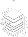
- FIG. 1 is an exploded perspective view of a rechargeable battery according to some embodiments of the present disclosure
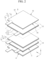
- FIG. 2 is an exploded perspective view of an electrode assembly in FIG. 1
- a rechargeable battery 1 may be formed by embedding an electrode assembly 10 in a case 20 along with an electrolyte.
- the electrode assembly 10 includes a separator 13, and a first electrode plate 11 and a second electrode plate 12 formed as a single sheet on both surfaces of the separator 13. That is, the electrode assembly 10 repeatedly comprises a structure in which the first electrode plate 11 and the second electrode plate 12 are arranged on both surfaces of the separator 13.
- the first electrode plate 11 is a positive electrode plate and has a positive active material layer 112 on both surfaces of an electrode current collecting plate 111.
- the electrode current collecting plate 111 has an electrode tab 113 of an uncoated region protruding from one side.
- the electrode tab 113 is drawn to the outside of the case when assembling the rechargeable battery by being directly formed or being connected or to the lead tab.
- the second electrode plate 12 is a negative electrode plate and is provided with a negative active material layer 122 on both surfaces of an electrode current collecting plate 121.
- the electrode current collecting plate 121 has an electrode tab 123 of an uncoated region protruding on one side.
- the electrode tab 123 is drawn to the outside of the case when assembling the rechargeable battery by being directly formed or being connected or to the lead tab.
- the case may be formed as a pouch or a can.
- the electrode tab 113 of the first electrode plate 11 and the electrode tab 123 of the second electrode plate 12 are drawn out in the same direction (a y-axis direction) and spaced apart from each other in a direction (an x-axis direction) that intersects the draw-out direction.
- the electrode assembly 10 is provided with a cross-sectional second electrode plate 14 on the upper and lower outermost surfaces.
- the cross-sectional second electrode plate 14 is placed on one side of the first electrode plate 11 on both sides of the stacking direction with the separator 13 interposed therebetween.
- the cross-sectional second electrode plate 14 is provided with a negative active material layer 142 on the cross-section of an electrode current collecting plate 141.
- the electrode current collecting plate 141 has an electrode tab 143, which is an uncoated region protruding on both sides spaced apart from each other.
- the electrode tab 143 is stacked with the electrode tab 123 of the second electrode plate 12 and then is drawn to the outside of the case when assembling the rechargeable battery by being directly formed or being connected to the lead tab.
- FIG. 3 is a plan view of an electrode assembly of FIG. 1 and FIG. 2 .
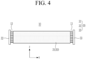
- FIG. 4 is a bottom view of FIG. 3 .
- FIG. 5 is a side view of FIG. 3 .
- the electrode assembly 10 includes a bonding part 30.
- the bonding part 30 is formed by bonding the separator 13 protruding to the outside of the first electrode plate 11 and the second electrode plate 12 with an adhesive on at least one surface facing the case 20.
- the electrode assembly 10 is formed in a plate shape corresponding to the internal shape of the case 20. In the first embodiment, the electrode assembly 10 is formed as a stack type.
- first bonding impregnation layer 31 may absorb the impact when a rechargeable battery 1 is dropped, and then may absorb and prevent the external impact from being transmitted to the bottom of the electrode assembly 10 through the case 20.
- the first bonding impregnation layer 31 may prevent pullback of the electrode assembly 10, where the first and second electrode plates 11 and 12 come out of the separator 13.
- the bonding part 30 includes a second bonding impregnation layer 32 and a third bonding impregnation layer 33 formed on the second side 102 and the third side 103 of the electrode assembly 10 - that is, the left-hand side and the right-hand side in FIG. 3 .
- the second and third bonding impregnation layers 32 and 33 are impregnated with the separator 13 on the second and third sides 102 and 103 of the electrode assembly 10 to attach and fix the multiple layers of the separator 13 to each other so that the first and second electrode plates 11 and 12 are fixed between the attached separators 13, thereby preventing them from protruding the separators 13.
- the second and third bonding impregnation layers 32 and 33 absorb the impact when the rechargeable battery 1 is dropped, thereby absorbing and preventing the external impact transmitted to the left-hand side and right-hand side of the electrode assembly 10 through the case 20.
- the second and third bonding impregnation layers 32 and 33 may prevent pullback on the electrode assembly 10, through which the first and second electrode plates 11 and 12 come out of the separator 13.
- the electrode assembly 10 is taped with an insulating tape 34 on the opposite side of the first bonding impregnation layer 31 - that is, on the side where the electrode tabs 113 and 123 are drawn out. Since the drop impact of the electrode assembly 10 does not flow into the insulating tape 34 side, a bonding part to mitigate the impact may not be provided.
- the insulating tape 34 holds the separator 13 and the first and second electrode plates 11 and 12 on the electrode tabs 113 and 123 side, bonding of the separator 13 by the bonding part 30 is made more stable.
- FIG. 6 is a bottom image of an electrode assembly according to some embodiments of the present disclosure.
- FIG. 7 is a partial plan view of FIG. 6 . Referring to FIG. 6 and FIG. 7 , the first bonding impregnation layer 31 of the bonding part 30 is described as an example.
- the first bonding impregnation layer 31 is formed by applying an adhesive with a thickness t1 of 118 ⁇ m to the entire surface of the first side 101, which is the bottom surface of the electrode assembly 10.
- the first bonding impregnation layer 31, which has the thickness t1 on the entire surface, has adherence and impact-absorption properties.
- the adhesive may be formed as a UV adhesive.
- the UV adhesive impregnates the adhesive and then is irradiated with UV light, thereby forming the bonding part 30 with adherence and impact-absorption properties. Therefore, the UV adhesive facilitates the formation of the bonding part 30.
- the adhesive may be formed as a polyethylene-based UV adhesive.
- the bonding part 30 is formed and impregnated at the aligned ends of the separator 13.
- the stack-type electrode assembly 10 is heat-pressurized for a period of time (e.g., a set or predetermined period of time) to compress the electrode assembly 10.
- a period of time e.g., a set or predetermined period of time
- the adhesive is impregnated and bonded to form a uniformly (or relatively uniformly) coated surface.
- the case 20 accommodating the electrode assembly 10 including the bonding part 30 is formed as a pouch.
- the case 20 is not limited to a pouch and may be formed as a square can.
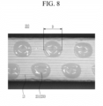
- FIG. 8 is a bottom image of an electrode assembly according to some embodiments of the present disclosure.
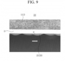
- FIG. 9 is a partial plan view of FIG. 8 . Referring to FIG. 8 and FIG. 9 , embodiments shown in FIGS. 8 and 9 illustrate a first bonding impregnation layer 231 among a bonding part 230 of an electrode assembly 210.
- the first bonding impregnation layer 231 is formed by applying the adhesive to the first side 101, which is the lower surface in the electrode assembly 210, in a plurality of dot lines (for example, 2 lines).
- the dot of the first bonding impregnation layer 231 is formed with a diameter D of 1.7 mm and a thickness t2 of 324 ⁇ m.
- the first bonding impregnation layer 231, which has the dot diameter and the thickness, has adherence and impact-absorption properties. The larger the dot diameter and thickness, the more excellent adherence and impact absorption may be achieved.
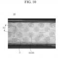
- FIG. 10 is an image of a bottom surface of an electrode assembly according to some embodiments of the present disclosure.
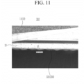
- FIG. 11 is a partial top plan view of FIG. 10 . Referring to FIG. 10 and FIG. 11 , the embodiments shown in FIGS. 10 and 11 illustrate a first bonding impregnation layer 331 of the bonding part 330 of the electrode assembly 310.
- the first bonding impregnation layer 331 is formed by applying the adhesive to the first side 101, which is the lower surface in the electrode assembly 310, in a plurality of dot lines (for example, 4 lines).
- the dot of the first bonding impregnation layer 331 is formed with a diameter D2 of 0.89 mm and a thickness t3 of 142 ⁇ m.
- the embodiments illustrated with respect to FIG. 10 and 11 have relatively more dot lines, so the dot diameter and the thickness are relatively smaller.
- the embodiments illustrated with respect to FIGS. 10 and 11 have a relatively wider adhesive area and a relatively smaller adhesive thickness, thereby giving similar adherence and impact-absorption properties to the embodiments illustrated and described with respect to FIG. 8 .
- FIG. 12 is a bottom view of an electrode assembly according to some embodiments of the present disclosure.
- a bonding part 430 of an electrode assembly 410 may be formed by repeatedly performing the process of being formed in the length direction (the x-axis direction) at one surface, formed in the thickness direction (the z-axis direction) at one end of the length direction, again formed in the length direction (the x-axis direction) at the end of the thickness direction, and again formed at one end of the length direction to the thickness direction (the z-axis direction).
- the method for forming the bonding part 430 of the embodiments illustrated with respect to FIG. 12 may be applied to forming the bonding parts (30, 230, and 330) of the embodiments illustrated with respect to FIGS. 1-11 .
- the embodiments illustrated with respect to FIG. 12 may relatively improve the workability of forming the bonding part 430 because there is no disconnection of the trajectory forming the bonding part 430.
- the quality of the length direction (the x-axis direction) may be uniform compared to the thickness direction (the z-axis direction) of the bonding part 430.
- FIG. 13 is a bottom view of an electrode according to some embodiments of the present disclosure.
- a bonding part 530 of the electrode assembly 510 may be formed by repeatedly performing the process of being formed in the length direction on one surface, formed inside the thickness direction at one end of the length direction, formed again in the opposite direction to the length direction at the end of the thickness direction, and formed again inside the thickness direction at one end of the length direction.
- the method for forming the bonding part 530 of the embodiments illustrated with respect to FIG. 13 may be applied to forming the bonding parts (30, 230, and 330) of the embodiments illustrated with respect to FIGS. 1-11 .
- the embodiments illustrated with respect to FIG. 13 may relatively improve the workability of forming the bonding part 530 because there is no disconnection of the trajectory forming the bonding part 530.
- the quality may be uniform in the thickness direction (the z-axis direction) and the length direction (the x-axis direction) of the bonding part 530.
- FIG. 14 is a bottom view of an electrode assembly according to some embodiments of the present disclosure.
- a bonding part 630 of an electrode assembly 610 may be formed on both sides of one surface by skipping the central part in the length direction.
- the bonding part 630 may be formed by repeatedly performing the process of being formed on both sides in the length direction by skipping a central part 620 on one surface, spaced apart in the thickness direction, and again formed on both sides in the opposite length direction by skipping the central part 620 again.
- the method for forming the bonding part 630 as illustrated with respect to FIG. 14 may be applied to forming the bonding parts 230 and 330 of the embodiments illustrated with respect to FIGS. 8-11 .
- the electrode assembly 610 may open the central part 620 and form the bonding part 630 on both sides thereof, so that it may have adherence and impact-absorption properties while simultaneously relatively improving the moisture-containing performance of the electrolyte solution. Additionally, the bonding parts 430 and 530 of the embodiments illustrated with respect to FIGS. 12 and 13 may be applied to the bonding parts 630 on both sides of the embodiments illustrated and described with respect to FIG. 14 .
- FIG. 15 is an exploded perspective view of a rechargeable battery according to some embodiments of the present disclosure.
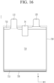
- FIG. 16 is a plan view of an electrode assembly in FIG. 15 .
- an electrode assembly 710 is formed of a jelly roll type.
- a bonding part 730 is formed by bonding a separator 713 protruding to the outside of a first electrode plate 711 and a second electrode plate 712 with adhesive on at least one surface facing the case 20. Since the jelly roll type electrode assembly 710 is wound, it is formed only on the first side at the bottom.
- the upper end of the electrode assembly 710 is taped with an insulating tape 34.
- the insulating tape 34 holds the separator 713 and the first and second electrode plates 711 and 712 on the electrode tabs 113 and 123, making the bonding of the separator 713 by the bonding part 730 more stable.
- the bonding part 730 may absorb the impact when the rechargeable battery 7 is dropped, thereby preventing external impact from being transmitted through the case 20 to the bottom of the electrode assembly 710.
- the bonding part 730 may prevent the pullback of the electrode assembly 710, in which first and second electrode plates 711 and 712 are outside of the separator 713.
Landscapes
- Chemical & Material Sciences (AREA)
- Chemical Kinetics & Catalysis (AREA)
- Electrochemistry (AREA)
- General Chemical & Material Sciences (AREA)
- Engineering & Computer Science (AREA)
- Manufacturing & Machinery (AREA)
- Secondary Cells (AREA)
- Cell Separators (AREA)
Applications Claiming Priority (1)
| Application Number | Priority Date | Filing Date | Title |
|---|---|---|---|
| KR1020230122654A KR20250039773A (ko) | 2023-09-14 | 2023-09-14 | 이차전지 |
Publications (2)
| Publication Number | Publication Date |
|---|---|
| EP4525113A2 true EP4525113A2 (de) | 2025-03-19 |
| EP4525113A3 EP4525113A3 (de) | 2025-06-04 |
Family
ID=92762410
Family Applications (1)
| Application Number | Title | Priority Date | Filing Date |
|---|---|---|---|
| EP24199700.6A Pending EP4525113A3 (de) | 2023-09-14 | 2024-09-11 | Wiederaufladbare batterie |
Country Status (4)
| Country | Link |
|---|---|
| US (1) | US20250096420A1 (de) |
| EP (1) | EP4525113A3 (de) |
| KR (1) | KR20250039773A (de) |
| CN (1) | CN119627374A (de) |
Family Cites Families (3)
| Publication number | Priority date | Publication date | Assignee | Title |
|---|---|---|---|---|
| JP2012069378A (ja) * | 2010-09-24 | 2012-04-05 | Sanyo Electric Co Ltd | 積層式電池 |
| KR102164003B1 (ko) * | 2018-11-19 | 2020-10-12 | 삼성에스디아이 주식회사 | 전극 조립체 및 그의 제조 방법 |
| ES3041563T3 (en) * | 2021-09-27 | 2025-11-12 | Lg Energy Solution Ltd | Electrode assembly and battery cell including the same |
-
2023
- 2023-09-14 KR KR1020230122654A patent/KR20250039773A/ko active Pending
-
2024
- 2024-07-22 US US18/780,338 patent/US20250096420A1/en active Pending
- 2024-09-11 EP EP24199700.6A patent/EP4525113A3/de active Pending
- 2024-09-11 CN CN202411270854.1A patent/CN119627374A/zh active Pending
Also Published As
| Publication number | Publication date |
|---|---|
| CN119627374A (zh) | 2025-03-14 |
| US20250096420A1 (en) | 2025-03-20 |
| KR20250039773A (ko) | 2025-03-21 |
| EP4525113A3 (de) | 2025-06-04 |
Similar Documents
| Publication | Publication Date | Title |
|---|---|---|
| KR101636371B1 (ko) | 계단 구조의 전지셀 | |
| EP3136495B1 (de) | Akku | |
| US12261308B2 (en) | Button cell | |
| US9608294B2 (en) | Electrode assembly having step portion in stabilized stacking and method of manufacturing the same | |
| KR101402657B1 (ko) | 비정형 구조의 전지팩 | |
| US9786874B2 (en) | Electrode having round corner | |
| US20160020434A1 (en) | Battery cell having round corner | |
| US20150364729A1 (en) | Rechargeable battery having corner folding portion | |
| US10593986B2 (en) | Rechargeable battery | |
| US12614793B2 (en) | Battery cell and battery cell manufacturing apparatus for manufacturing the same | |
| US20240283003A1 (en) | Electrode Assembly and Battery Cell Including the Same | |
| KR102266592B1 (ko) | 이차 전지 | |
| JP2025039726A (ja) | 二次電池の製造方法および二次電池 | |
| KR101825007B1 (ko) | 파우치형 이차전지 및 그 제조방법 | |
| EP2843747B1 (de) | Elektrodenanordnung mit einem schrittelement in stabilisierter stapelung und verfahren zur herstellung davon | |
| EP4525113A2 (de) | Wiederaufladbare batterie | |
| US20250070215A1 (en) | Electrode assembly for secondary battery | |
| US20240186559A1 (en) | Method for assemblying battery assembly, battery assembly, and secondary battery comprising same | |
| US20230411769A1 (en) | Battery Cell And Battery Cell Manufacturing Apparatus For Manufacturing Same | |
| KR102630997B1 (ko) | 이차전지 | |
| US20250167275A1 (en) | Taping device for secondary battery and secondary battery manufactured using the same | |
| KR102622632B1 (ko) | 전극 조립체 및 이를 포함하는 전지 셀 | |
| KR102956955B1 (ko) | 응력 완화부가 형성된 전극 탭을 포함하는 배터리 셀 | |
| KR102888921B1 (ko) | 이차전지 제조방법 및 이차전지 | |
| US20240266643A1 (en) | Rechargeable battery |
Legal Events
| Date | Code | Title | Description |
|---|---|---|---|
| PUAI | Public reference made under article 153(3) epc to a published international application that has entered the european phase |
Free format text: ORIGINAL CODE: 0009012 |
|
| STAA | Information on the status of an ep patent application or granted ep patent |
Free format text: STATUS: REQUEST FOR EXAMINATION WAS MADE |
|
| 17P | Request for examination filed |
Effective date: 20240911 |
|
| AK | Designated contracting states |
Kind code of ref document: A2 Designated state(s): AL AT BE BG CH CY CZ DE DK EE ES FI FR GB GR HR HU IE IS IT LI LT LU LV MC ME MK MT NL NO PL PT RO RS SE SI SK SM TR |
|
| PUAL | Search report despatched |
Free format text: ORIGINAL CODE: 0009013 |
|
| AK | Designated contracting states |
Kind code of ref document: A3 Designated state(s): AL AT BE BG CH CY CZ DE DK EE ES FI FR GB GR HR HU IE IS IT LI LT LU LV MC ME MK MT NL NO PL PT RO RS SE SI SK SM TR |
|
| RIC1 | Information provided on ipc code assigned before grant |
Ipc: H01M 50/46 20210101ALI20250429BHEP Ipc: H01M 50/105 20210101ALI20250429BHEP Ipc: H01M 10/0587 20100101ALI20250429BHEP Ipc: H01M 10/0585 20100101ALI20250429BHEP Ipc: H01M 10/04 20060101AFI20250429BHEP |