EP4525111A1 - System for pressing and charging/discharging battery cell - Google Patents
System for pressing and charging/discharging battery cell Download PDFInfo
- Publication number
- EP4525111A1 EP4525111A1 EP23863502.3A EP23863502A EP4525111A1 EP 4525111 A1 EP4525111 A1 EP 4525111A1 EP 23863502 A EP23863502 A EP 23863502A EP 4525111 A1 EP4525111 A1 EP 4525111A1
- Authority
- EP
- European Patent Office
- Prior art keywords
- battery cell
- pressurizing
- charging
- tab
- pressurization
- Prior art date
- Legal status (The legal status is an assumption and is not a legal conclusion. Google has not performed a legal analysis and makes no representation as to the accuracy of the status listed.)
- Pending
Links
Images




Classifications
-
- H—ELECTRICITY
- H02—GENERATION; CONVERSION OR DISTRIBUTION OF ELECTRIC POWER
- H02J—ELECTRIC POWER NETWORKS; CIRCUIT ARRANGEMENTS OR SYSTEMS FOR SUPPLYING OR DISTRIBUTING ELECTRIC POWER; SYSTEMS FOR STORING ELECTRIC ENERGY
- H02J7/00—Circuit arrangements for charging or discharging batteries or for supplying loads from batteries
- H02J7/70—Circuit arrangements for charging or discharging batteries or for supplying loads from batteries characterised by the mechanical construction
-
- H—ELECTRICITY
- H01—ELECTRIC ELEMENTS
- H01M—PROCESSES OR MEANS, e.g. BATTERIES, FOR THE DIRECT CONVERSION OF CHEMICAL ENERGY INTO ELECTRICAL ENERGY
- H01M10/00—Secondary cells; Manufacture thereof
- H01M10/04—Construction or manufacture in general
- H01M10/0404—Machines for assembling batteries
-
- H—ELECTRICITY
- H01—ELECTRIC ELEMENTS
- H01M—PROCESSES OR MEANS, e.g. BATTERIES, FOR THE DIRECT CONVERSION OF CHEMICAL ENERGY INTO ELECTRICAL ENERGY
- H01M10/00—Secondary cells; Manufacture thereof
- H01M10/04—Construction or manufacture in general
- H01M10/0481—Compression means other than compression means for stacks of electrodes and separators
-
- H—ELECTRICITY
- H01—ELECTRIC ELEMENTS
- H01M—PROCESSES OR MEANS, e.g. BATTERIES, FOR THE DIRECT CONVERSION OF CHEMICAL ENERGY INTO ELECTRICAL ENERGY
- H01M10/00—Secondary cells; Manufacture thereof
- H01M10/42—Methods or arrangements for servicing or maintenance of secondary cells or secondary half-cells
- H01M10/44—Methods for charging or discharging
- H01M10/441—Methods for charging or discharging for several batteries or cells simultaneously or sequentially
-
- H—ELECTRICITY
- H01—ELECTRIC ELEMENTS
- H01M—PROCESSES OR MEANS, e.g. BATTERIES, FOR THE DIRECT CONVERSION OF CHEMICAL ENERGY INTO ELECTRICAL ENERGY
- H01M50/00—Constructional details or processes of manufacture of the non-active parts of electrochemical cells other than fuel cells, e.g. hybrid cells
- H01M50/50—Current conducting connections for cells or batteries
- H01M50/543—Terminals
- H01M50/547—Terminals characterised by the disposition of the terminals on the cells
- H01M50/548—Terminals characterised by the disposition of the terminals on the cells on opposite sides of the cell
-
- H—ELECTRICITY
- H01—ELECTRIC ELEMENTS
- H01M—PROCESSES OR MEANS, e.g. BATTERIES, FOR THE DIRECT CONVERSION OF CHEMICAL ENERGY INTO ELECTRICAL ENERGY
- H01M50/00—Constructional details or processes of manufacture of the non-active parts of electrochemical cells other than fuel cells, e.g. hybrid cells
- H01M50/50—Current conducting connections for cells or batteries
- H01M50/543—Terminals
- H01M50/552—Terminals characterised by their shape
- H01M50/553—Terminals adapted for prismatic, pouch or rectangular cells
- H01M50/557—Plate-shaped terminals
-
- Y—GENERAL TAGGING OF NEW TECHNOLOGICAL DEVELOPMENTS; GENERAL TAGGING OF CROSS-SECTIONAL TECHNOLOGIES SPANNING OVER SEVERAL SECTIONS OF THE IPC; TECHNICAL SUBJECTS COVERED BY FORMER USPC CROSS-REFERENCE ART COLLECTIONS [XRACs] AND DIGESTS
- Y02—TECHNOLOGIES OR APPLICATIONS FOR MITIGATION OR ADAPTATION AGAINST CLIMATE CHANGE
- Y02E—REDUCTION OF GREENHOUSE GAS [GHG] EMISSIONS, RELATED TO ENERGY GENERATION, TRANSMISSION OR DISTRIBUTION
- Y02E60/00—Enabling technologies; Technologies with a potential or indirect contribution to GHG emissions mitigation
- Y02E60/10—Energy storage using batteries
-
- Y—GENERAL TAGGING OF NEW TECHNOLOGICAL DEVELOPMENTS; GENERAL TAGGING OF CROSS-SECTIONAL TECHNOLOGIES SPANNING OVER SEVERAL SECTIONS OF THE IPC; TECHNICAL SUBJECTS COVERED BY FORMER USPC CROSS-REFERENCE ART COLLECTIONS [XRACs] AND DIGESTS
- Y02—TECHNOLOGIES OR APPLICATIONS FOR MITIGATION OR ADAPTATION AGAINST CLIMATE CHANGE
- Y02P—CLIMATE CHANGE MITIGATION TECHNOLOGIES IN THE PRODUCTION OR PROCESSING OF GOODS
- Y02P70/00—Climate change mitigation technologies in the production process for final industrial or consumer products
- Y02P70/50—Manufacturing or production processes characterised by the final manufactured product
Definitions
- the present invention relates to a battery cell pressurization and charging/discharging system, and more particularly, to a battery cell pressurization and charging/discharging system in which a battery cell can be pressurized and charged/discharged without changing its inner frame, even if the size of the battery cell is changed.
- lithium secondary batteries such as lithium-ion batteries, lithium-ion polymer batteries, and lithium all-solid-state batteries, which have advantages such as high energy density, discharge voltage, and output stability.
- Such a secondary battery has an electrode assembly comprising an anode, a cathode, a separator disposed therebetween, and an electrolyte embedded inside a battery case, with anode and cathode tabs welded to two electrode tabs and sealed to be exposed to the outside of the battery case. These electrode tabs are electrically connected to an external device by contact, and the battery can supply power to or receive power from the external device through the electrode tabs.
- the secondary battery may be fabricated by accommodating the electrode assembly into the battery case and injecting electrolyte, followed by an activation step to activate the battery.
- the activation step may comprise mounting the secondary battery to the frame in a charge and discharge device and then charging/discharging the secondary battery under pressure to the conditions required for activation.
- a battery cell pressurization and charge/discharge system comprises: an inner frame into which a battery cell is loaded; a plate for pressurizing the battery cell; a pressurizing block movable on the plate in a direction in which the plate extends, and gripping the battery cell; and an outer frame disposed outside the inner frame, and having an inner tab electrically connected with the pressurizing block by wiring.
- the pressurizing block may comprise a circuit board disposed in a portion in contact with the battery cell.
- the system may further comprise a load cell disposed within the inner frame and capable of measuring a pressure exerted on the battery cell.
- system may further comprise a pressurizing shaft for pressurizing the plate, wherein the pressurizing shaft pressurizes the plate by rotation.
- the rotation may be a screw rotation.
- the pressurizing block may grip a tab of the battery cell.
- the battery cell may be a bilateral tabbed battery cell with tabs provided at both ends.
- the battery cell may be a unidirectionally tabbed battery cell having a tab provided at one end only.
- two or more pressurizing blocks may be disposed on the one plate.
- the system may further comprise: a transfer device to transfer the outer frame; and a charging/discharging device into which the transferred outer frame is placed, wherein the charging/discharging device has an outer tab electrically connected with the inner tab, and wherein a current applied by the charging device is transferred to the battery cell via the outer tab, the inner tab, and the pressurizing block.
- the outer tab may be a tab gripper that grips and electrically connects the inner tab.
- the wiring may connect the inner tab and the pressurizing block in a form of a spring.
- a battery cell pressurization and charging/discharging system can pressurize battery cells of various sizes without changing the inner frame, by having pressurizing blocks movable on the plate gripping the tabs of the battery cells, regardless of the size of the battery cells.
- Wiring disposed in the form of a spring may be elongated. Accordingly, the inner tabs may be connected to the pressurizing blocks by wiring that stretches in length while remaining fixed in position within the outer frame. If the pressurizing block is moved, the position of the inner tabs may not change, but only the length of the wiring may increase or decrease.
- the outer tab may be fixedly disposed in a position corresponding to the inner tabs within the outer frame.
- the battery cell pressurization and charging/discharging system can use the same inner frame, outer frame, and charging/discharging device regardless of the size of the battery cells. Accordingly, the battery cell pressurization and charging/discharging system can save time and money compared to conventional pressurization and charging/discharging systems that require replacing the frame whenever the size of the battery cell changes.
- FIG. 1 is a block diagram schematically illustrating a battery cell pressurization and charging/discharging system according to one embodiment of the present invention.
- a battery cell pressurization and charging/discharging system 1000 may include a pressurizing tray 1, a transfer device 2, and a charging/discharging device 3.
- the pressurizing tray 1 may pressurize battery cells.
- the pressurizing tray 1 may be loaded with the battery cells.
- the charging/discharging device 3 may charge and discharge the battery cells placed in the pressurizing tray 1.
- the process of charging/discharging the battery cells may be defined as an activation process that activates the battery cells. During the activation process, the battery cell may expand due to a change in the thickness of the electrode plate or gas generation.
- the battery cell pressurization and charging/discharging system 1000 allows the charging/discharging device 3 to charge the battery cell while the pressurizing tray 1 pressurizes the battery cell to prevent the battery cells from expanding.
- the pressurizing tray 1 containing the battery cells may be transferred to the charging/discharging device 3 by the transfer device 2.
- the transfer device 2 can be used in various ways, as long as it is capable of transferring the pressurizing tray 1 to the charging/discharging device 3.
- the transfer device 2 may comprise a conveyor belt, a crane, or the like. As a crane, a stacker crane may be used.
- the battery cells may be loaded into the pressurizing tray 1.
- the pressurizing tray 1 can be moved to the charging/discharging device 3 via a conveyor belt while pressurizing the loaded battery cells. A stacker crane may then load the pressurizing tray 1 into the charging/discharging device 3.
- the pressurizing tray 1 may be introduced into the charging/discharging device 3 by the transfer device 2 so as to be electrically connected to the charging/discharging device 3.
- the charging/discharging device 3 may apply a current to the pressurizing tray 1.
- FIG. 2 is a drawing illustrating one embodiment of the pressurizing tray of FIG. 1
- FIG. 3 is a drawing illustrating battery cells pressurized inside the pressurizing tray of FIG. 1 .
- the pressurizing tray 1 may include an inner frame 10, an outer frame 20, battery cells 30, plates, pressurizing shafts 120, a pressurizing adjustment member 130, a load cell 140, pressurizing blocks 150, inner tabs 160, and wiring 170.
- the plates may include a main plate 100 and sub-plates 110.
- the inner frame 10 may provide a space in which the battery cells 30 are housed.
- the inner frame 10 may be made of rigid materials to accommodate and secure the battery cells 30.
- the inner frame 10 may be loaded with the battery cells 30.
- the battery cells 30 may be activated by pressurizing and charging/discharging the battery cells 30 after they are inserted into the inner frame 10. At least one battery cell 30 may be introduced.
- the main plate 100 and the sub-plates 110 may pressurize the battery cells 30.
- the main plate 100 may have a plate-like structure.
- the main plate 100 may extend in a first direction DR1.
- the main plate 100 may pressurize in a second direction DR2 perpendicular to the first direction DR1.
- the main plate 100 may be made of a material with high mechanical stiffness that does not deform under high heat and pressure.
- the main plate 100 may be constructed of a metallic material.
- the main plate 100 may be made of a material other than metal, such as aluminum, stainless steel, reinforced plastic, reinforced ceramic, or reinforced glass, as long as the material has good mechanical rigidity.
- the main plate 100 and the sub-plates 110 may have slip sheets secured between them.
- the slip sheets may be pinned to the top of the main plate 100 and the sub-plates 110 and may serve to hold the battery cells before the battery cells are pressurized.
- the slip sheets may have a length that is less than the size of the battery cells.
- the slip sheets are disposed at a length that covers the bodies of the battery cells. If the tabs of the battery cells are covered by the slip sheets, the pressurizing blocks 150 cannot be electrically connected to the tabs of the battery cells.
- Each of the slip sheets may comprise a flame retardant coated paper or film.
- a plurality of battery cells 30 along with the main plate 100 and sub-plates 110 may be disposed in the inner frame 10, with the main plate 100 and sub-plates 110 positioned adjacent to each of the plurality of battery cells 30.
- Each of the battery cells 30 may be pressurized by the adjacent main plate 100 and the sub-plates 110.
- the pressurizing shafts 120 and the pressurizing adjustment member 130 can pressurize the main plate 100.
- the pressurizing adjustment member 130 can rotate each of the pressurizing shafts 120 by rotating a gear.
- each of the pressurizing shafts 120 can pressurize the main plate 100 by rotating a screw.
- the pressure exerted on the main plate 100 can be transmitted to the sub-plates 110, whereby the plurality of battery cells 30 can be pressurized together.
- Each of the pressurizing shafts 120 may have threads, and the sub-plates 110 may be in contact with the threads by bearings or the like. This allows the sub-plates 110 to be moved in the second direction DR2 by rotation of the screw on each of the pressurizing shafts 120.
- a mounting shaft for mounting the main plate 100 and the sub-plates 110 may be added.
- the load cell 140 may measure the pressure applied to the battery cells 30.
- the load cell 140 may be disposed within the inner frame 10 in a direction in which the pressurizing shafts 120 apply pressure. As shown in FIG. 3 , when pressure is applied by the pressurizing shafts 120, the load cell 140 may be in contact with one of the sub-plates 110, and the sub-plate 110 may apply pressure to the load cell 140.
- the load cell 140 can generate a signal to stop pressurizing if pressure is applied above a preset pressure. For example, the load cell 140 can generate a signal to stop pressurization if a pressure greater than 3000 kgf is applied. In doing so, the pressurizing tray 1 can prevent the battery cell 30 from being damaged by excessive pressure being applied to the battery cell 30.
- the load cell 140 is electrically connected and operable only during the pressurization stage, and not during the charging/discharging process.
- the pressurizing blocks 150 may be disposed on the main plate 100 and the sub-plates 110.
- the pressurizing blocks 150 may move on the main plate 100 and the sub-plates 110 in a direction in which the main plate 100 and the sub-plates 110 extend, i.e., the pressurizing blocks 150 may move in the first direction DR1. Accordingly, even if the length of each of the battery cells 30 in the first direction DR1 changes, the inner frame 10 can be moved to grip the battery cells 30 with different lengths by moving only the pressurizing blocks 150 without having to change the inner frame 10.
- Each of the pressurizing blocks 150 may be electrically connected to the wiring 170.
- the pressurizing blocks 150 may be in contact with tabs on the battery cells 30.
- the battery cells 30 illustrated in FIGS. 2 and 3 may be defined as bilateral tabbed battery cells each with tabs located at both ends.
- the pressurizing blocks 150 may each be in contact with a tab located at one of both ends of the battery cell 30.
- the pressurizing blocks 150 may include a circuit board disposed in contact with the corresponding battery cell 30.
- the circuit board may be a printed circuit board. Through the circuit board, the pressurizing blocks 150 may be electrically connected to the battery cells 30.
- the inner tabs 160 may be disposed on an inner side of the outer frame 20.
- the inner tabs 160 may be connected to the pressurizing blocks 150 by the wiring 170. Accordingly, signals communicated to the inner tabs 160 from the outside may be communicated to the pressurizing blocks 150 via the wiring 170.
- the wiring 170 may be provided in a form of a spring to facilitate length variation. Accordingly, the wiring 170 may not be disconnected when the main plate 100 and sub-plates 110 are moved in the second direction DR2. If the wiring 170 has a fixed length, the wiring 170 may be disconnected from the pressurizing blocks 150 as the main plate 100 and the sub-plates 110 move. Thereafter, signals communicated to the main plate 100 may be communicated to the battery cell 30 via the pressurizing block 150. In other words, the inner tab 160, the wiring 170, the pressurizing block 150, and the battery cell 30 may be electrically connected.
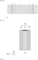
- FIGS. 4a to 4c are drawings illustrating one embodiment of a pressurizing block included in the pressurizing tray of FIG. 1 .
- FIG. 4a is a view of a sub-plate 110 from a second direction DR2
- FIG. 4b is a view of the sub-plate 110 from a direction opposite to the second direction DR2.
- holes H may be formed at both ends of the sub-plate 110.
- Pressurizing shafts 120 as described above may be disposed through the holes H.
- Pressurizing blocks 150 may be disposed on the sub-plate 110.
- Each of the pressurizing blocks 150 may move on the sub-plates 110 in the first direction DR1 and in a direction opposite to the first direction DR1. This allows each of the pressurizing blocks 150 to move to contact the tab of the battery cell even when the length of the battery cell in the first direction DR1 changes.
- FIG. 4c is a side view of the sub-plate 110.
- the pressurizing block 150 may include a first sub-pressurizing block 151, a second sub-pressurizing block 152, and a connecting member 153.
- the first sub-pressurizing block 151 and the second sub-pressurizing block 152 may be connected by the connecting member 153.
- the pressurizing blocks 150 may be disposed on the sub-plates 110 with the plurality of members connected, and may move in the first direction DR1 and in a direction opposite to the first direction DR1.
- the first sub-pressurizing block 151 may include a coil spring. Accordingly, the first sub-pressurizing block 151 may be compressed when the tabs of the battery cells are pressed.
- a circuit board may be disposed in the second sub-pressurizing block 152. At this time, the second sub-pressurizing block 152 may be connected with the wiring 170 described in FIGS. 2 and 3 . Accordingly, the pressurizing block 150 may be electrically connected to the tabs of the battery cell via the second sub-pressurizing block 152.
- a circuit board is disposed in the first sub-pressurizing block 151 and that the second sub-pressurizing block 152 comprises a spring.
- FIGS. 4a to 4c have been described with reference to the sub-plates 110, the same can be applied to the main plate 100.
- FIG. 5 is a drawing illustrating a cell battery pressurization and charging/discharging system according to one embodiment of the present invention.
- the pressurizing tray 1, which is introduced into the charging/discharging device 3 by the transfer device 2, may be electrically connected to the charging/discharging device 3.
- the charging/discharging device 3 may include outer tabs 180 disposed internally, and the outer tabs 180 may have a form of grippers. Accordingly, the outer tabs 180 may be defined as tab grippers. The outer tabs 180 may contact the inner tabs 160 by gripping the inner tabs 160, and may be electrically connected to the inner tabs 160. Alternatively, the outer tabs 180 and the inner tabs 160 may include a conductive material internally and may be electrically connected by contacting each other. Alternatively, the outer tabs 180 and the inner tabs 160 may each include a circuit board at an end thereof, and may be electrically connected to each other by contacting the respective ends. As such, the charging/discharging device 3 may provide currents through the outer tabs 180 to the inner tabs 160. The current may be delivered to the battery cells 30 and serve to charge and discharge the battery cells 30.
- the wiring 170 which is provided in the form of springs, may be elongated. Accordingly, the inner tabs 160 may be connected to the pressurizing blocks 150 by the wiring 170 with fixed positions within the outer frame 20. When the main plate 100 and sub-plates 110 are moved in the second direction DR2, the positions of the inner tabs 160 may not change and only the length of the wiring 170 may increase or decrease.
- the outer tabs 180 may be fixedly disposed in positions corresponding to the inner tabs 160 within the outer frame 20. That is, the positions of the inner tabs 160 and the outer tab 180 are each fixed.
- FIG. 6 is a drawing illustrating a pressurizing tray according to one embodiment of the present invention.
- FIG. 6 may be substantially identical to FIG. 1 , except that the lengths of the first direction DR1 of the battery cells 30 are reduced. Accordingly, a description of the duplicate configuration will be omitted.
- the pressurizing blocks 150 may move on the main plate 100 and the sub-plates 110 to conform to the lengths of the battery cell 30s when the lengths of the battery cells 30 change. After traveling, the pressurizing blocks 150 can grip the tabs of the battery cells 30.
- the pressurizing blocks 150 may be electrically connected to the battery cells 30 by gripping the tabs of the battery cells 30.
- a circuit board may be disposed at the portion where each of the pressurizing blocks 150 grips the tabs of the battery cells 30.
- the circuit board may be a printed circuit board.
- FIG. 7 is a drawing illustrating a pressurizing tray according to one embodiment of the present invention.
- FIG. 7 may be substantially identical to FIG. 1 , except that the battery cells 30 have been changed to unilateral tabbed battery cells. Accordingly, a description of the duplicate configuration will be omitted.
- the battery cells 30 may be unidirectional tabbed battery cells rather than bidirectional tabbed battery cells.
- a unidirectional tabbed battery cell may be defined as a battery cell in which the tabs are located on only one side of the battery cell. In this case, battery cells 30 may have tabs located on one end only.
- the pressurizing blocks 150 which are movable on the main plate 100, may each be in contact with different battery cells 30.
- a pressurizing block 150 positioned at an end of the first direction DR1 of one sub-plate 110 contacts a battery cell 30 positioned in the first direction DR1 of the battery cells 30 positioned adjacent to the sub-plate 110, and a pressurizing block 150 positioned in a direction opposite to the first direction DR1 may contact the battery cells 30 positioned in a direction opposite to the first direction DR1 among the battery cells 30 positioned adjacent to the sub-plate 110.
- the structure of the pressurizing blocks 150 may be somewhat different from that described above, since the unidirectional tabbed battery cell may have two tabs on one side only. This will be described with reference to FIGS. 8a to 8c .
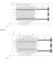
- FIGS. 8a to 8c are drawings illustrating one embodiment of a pressurizing block included in the pressurizing tray of FIG. 7 .
- FIGS. 8a to 8c may be substantially the same as FIGS. 4a to 4c , except for the addition of the insulating member 155. Accordingly, a description of overlapping configurations will be omitted.
- the insulating member 155 may be disposed between the first sub-pressurizing block 151 and the second sub-pressurizing block 152.
- the insulating member 155 may also be disposed in only one of the first sub-pressurizing block 151 and the second sub-pressurizing block 152.
- the insulating member 155 may be disposed only on the first sub-pressurizing block 151 side.
- the insulating member 155 can be disposed only on the second sub-pressurizing block 152 side.
- the insulating member 155 may serve to insulate the circuit boards disposed at the top and bottom of the sub-pressurizing block where the circuit boards are disposed. Thus, an upper portion of the sub-pressurizing block in which the circuit board is disposed may contact a tab of one of the two tabs of the battery cell, and a lower portion of the sub-pressurizing block may contact a tab of the other of the two tabs of the battery cell.
- a plurality of wirings 170 shown in FIG. 7 may be provided and connected to the top and bottom of the sub-pressurizing block, respectively.
Landscapes
- Chemical & Material Sciences (AREA)
- Chemical Kinetics & Catalysis (AREA)
- Electrochemistry (AREA)
- General Chemical & Material Sciences (AREA)
- Engineering & Computer Science (AREA)
- Manufacturing & Machinery (AREA)
- Power Engineering (AREA)
- Battery Mounting, Suspending (AREA)
- Secondary Cells (AREA)
Abstract
Description
- The present application claims the benefit of and priority to
Korean Patent Application No. 10-2022-0113937, filed September 8, 2022 - The present invention relates to a battery cell pressurization and charging/discharging system, and more particularly, to a battery cell pressurization and charging/discharging system in which a battery cell can be pressurized and charged/discharged without changing its inner frame, even if the size of the battery cell is changed.
- In recent years, as energy prices have risen due to the depletion of fossil fuels and environmental pollution has increased, there has been a growing need for environmentally friendly alternative energy sources. As a result, various power generation technologies such as nuclear, wind, tidal, and solar are being researched, and there is a growing interest in power storage to use the energy generated more efficiently.
- In particular, the demand for batteries as an energy source is increasing rapidly as technology development and demand for medium and large-scale applications such as electric vehicles and energy storage systems (ESS) increases, and research is being conducted on batteries that can meet various needs.
- For example, in terms of battery shape, there is a high demand for prismatic batteries and pouch batteries with thin thickness, and in terms of materials, there is a high demand for lithium secondary batteries such as lithium-ion batteries, lithium-ion polymer batteries, and lithium all-solid-state batteries, which have advantages such as high energy density, discharge voltage, and output stability.
- Such a secondary battery has an electrode assembly comprising an anode, a cathode, a separator disposed therebetween, and an electrolyte embedded inside a battery case, with anode and cathode tabs welded to two electrode tabs and sealed to be exposed to the outside of the battery case. These electrode tabs are electrically connected to an external device by contact, and the battery can supply power to or receive power from the external device through the electrode tabs.
- In one aspect, the secondary battery may be fabricated by accommodating the electrode assembly into the battery case and injecting electrolyte, followed by an activation step to activate the battery. The activation step may comprise mounting the secondary battery to the frame in a charge and discharge device and then charging/discharging the secondary battery under pressure to the conditions required for activation.
- If the size of the electrode assembly changes, the frame must be reused to fit the new size. As a result, the time and cost of fabricating the secondary battery is wasted. Therefore, research is being conducted to solve these problems.
- It is an object of the present invention to provide a battery cell pressurization and charging/discharging system in which pressurization and charging/discharging can be performed using the same frame even when the size of the electrode assembly changes.
- Furthermore, it is an object of the present invention to provide a battery cell pressurization and charging/discharging system that allows for the use of a battery cell for capacity testing, rather than the use of a battery cell dedicated to charging/discharging.
- To accomplish the aforementioned objectives of the present invention, a battery cell pressurization and charge/discharge system according to one embodiment of the present invention comprises: an inner frame into which a battery cell is loaded; a plate for pressurizing the battery cell; a pressurizing block movable on the plate in a direction in which the plate extends, and gripping the battery cell; and an outer frame disposed outside the inner frame, and having an inner tab electrically connected with the pressurizing block by wiring.
- In one embodiment, the pressurizing block may comprise a circuit board disposed in a portion in contact with the battery cell.
- In one embodiment, the system may further comprise a load cell disposed within the inner frame and capable of measuring a pressure exerted on the battery cell.
- In one embodiment, the system may further comprise a pressurizing shaft for pressurizing the plate, wherein the pressurizing shaft pressurizes the plate by rotation.
- In one embodiment, the rotation may be a screw rotation.
- In one embodiment, the pressurizing block may grip a tab of the battery cell.
- In one embodiment, the battery cell may be a bilateral tabbed battery cell with tabs provided at both ends.
- In one embodiment, the battery cell may be a unidirectionally tabbed battery cell having a tab provided at one end only.
- In one embodiment, two or more pressurizing blocks may be disposed on the one plate.
- In one embodiment, the system may further comprise: a transfer device to transfer the outer frame; and a charging/discharging device into which the transferred outer frame is placed, wherein the charging/discharging device has an outer tab electrically connected with the inner tab, and wherein a current applied by the charging device is transferred to the battery cell via the outer tab, the inner tab, and the pressurizing block.
- In one embodiment, the outer tab may be a tab gripper that grips and electrically connects the inner tab.
- In one embodiment, the wiring may connect the inner tab and the pressurizing block in a form of a spring.
- According to the present invention, a battery cell pressurization and charging/discharging system can pressurize battery cells of various sizes without changing the inner frame, by having pressurizing blocks movable on the plate gripping the tabs of the battery cells, regardless of the size of the battery cells.
- Wiring disposed in the form of a spring may be elongated. Accordingly, the inner tabs may be connected to the pressurizing blocks by wiring that stretches in length while remaining fixed in position within the outer frame. If the pressurizing block is moved, the position of the inner tabs may not change, but only the length of the wiring may increase or decrease. The outer tab may be fixedly disposed in a position corresponding to the inner tabs within the outer frame.
- Thus, the battery cell pressurization and charging/discharging system can use the same inner frame, outer frame, and charging/discharging device regardless of the size of the battery cells. Accordingly, the battery cell pressurization and charging/discharging system can save time and money compared to conventional pressurization and charging/discharging systems that require replacing the frame whenever the size of the battery cell changes.
-
-
FIG. 1 is a block diagram schematically illustrating a battery cell pressurization and charging/discharging system according to one embodiment of the present invention. -
FIG. 2 is a drawing illustrating one embodiment of the pressurizing tray ofFIG. 1 . -
FIG. 3 is a drawing of a pressurized state of battery cell placed inside the pressurizing tray ofFIG. 1 . -
FIGS. 4a to 4c are drawings illustrating one embodiment of a pressurizing block included in the pressurizing tray ofFIG. 1 . -
FIG. 5 is a drawing illustrating a cell battery pressurization and charging/discharging system according to one embodiment of the present invention. -
FIG. 6 is a drawing illustrating a pressurizing tray according to one embodiment of the present invention. -
FIG. 7 is a drawing illustrating a pressurizing tray according to one embodiment of the present invention. -
FIGS. 8a to 8c are drawings illustrating one embodiment of a pressurizing block included in the pressurizing tray ofFIG. 7 . - Hereinafter, preferred embodiments of the present invention will be described in detail with reference to the accompanying drawings. It should be noted that the terms and words used in this specification and claims are not to be construed in their ordinary or dictionary sense, but rather in a sense and concept consistent with the technical idea of the present invention, based on the principle that the inventor may properly define the concept of a term to best describe his invention. Accordingly, it is to be understood that the embodiments described in the specification and the configurations illustrated in the drawings are only some of the most preferred embodiments of the present invention and are not exhaustive of the technical ideas of the present invention, and that there may be various equivalents and modifications that may replace them at the time of filing.
-
FIG. 1 is a block diagram schematically illustrating a battery cell pressurization and charging/discharging system according to one embodiment of the present invention. - Referring to
FIG. 1 , a battery cell pressurization and charging/discharging system 1000 may include a pressurizing tray 1, a transfer device 2, and a charging/discharging device 3. The pressurizing tray 1 may pressurize battery cells. For this purpose, the pressurizing tray 1 may be loaded with the battery cells. The charging/discharging device 3 may charge and discharge the battery cells placed in the pressurizing tray 1. The process of charging/discharging the battery cells may be defined as an activation process that activates the battery cells. During the activation process, the battery cell may expand due to a change in the thickness of the electrode plate or gas generation. The battery cell pressurization and charging/discharging system 1000 allows the charging/discharging device 3 to charge the battery cell while the pressurizing tray 1 pressurizes the battery cell to prevent the battery cells from expanding. - The pressurizing tray 1 containing the battery cells may be transferred to the charging/discharging device 3 by the transfer device 2. The transfer device 2 can be used in various ways, as long as it is capable of transferring the pressurizing tray 1 to the charging/discharging device 3. The transfer device 2 may comprise a conveyor belt, a crane, or the like. As a crane, a stacker crane may be used. For example, in the pressurizing stage, the battery cells may be loaded into the pressurizing tray 1. The pressurizing tray 1 can be moved to the charging/discharging device 3 via a conveyor belt while pressurizing the loaded battery cells. A stacker crane may then load the pressurizing tray 1 into the charging/discharging device 3.
- The pressurizing tray 1 may be introduced into the charging/discharging device 3 by the transfer device 2 so as to be electrically connected to the charging/discharging device 3. The charging/discharging device 3 may apply a current to the pressurizing tray 1.
-
FIG. 2 is a drawing illustrating one embodiment of the pressurizing tray ofFIG. 1 , andFIG. 3 is a drawing illustrating battery cells pressurized inside the pressurizing tray ofFIG. 1 . - Referring to
FIG. 2 , the pressurizing tray 1 may include aninner frame 10, an outer frame 20,battery cells 30, plates, pressurizingshafts 120, a pressurizingadjustment member 130, aload cell 140, pressurizingblocks 150,inner tabs 160, andwiring 170. The plates may include amain plate 100 and sub-plates 110. - The
inner frame 10 may provide a space in which thebattery cells 30 are housed. Theinner frame 10 may be made of rigid materials to accommodate and secure thebattery cells 30. Theinner frame 10 may be loaded with thebattery cells 30. Thebattery cells 30 may be activated by pressurizing and charging/discharging thebattery cells 30 after they are inserted into theinner frame 10. At least onebattery cell 30 may be introduced. - The
main plate 100 and the sub-plates 110 may pressurize thebattery cells 30. To this end, themain plate 100 may have a plate-like structure. Themain plate 100 may extend in a first direction DR1. Themain plate 100 may pressurize in a second direction DR2 perpendicular to the first direction DR1. To accomplish this, themain plate 100 may be made of a material with high mechanical stiffness that does not deform under high heat and pressure. For example, themain plate 100 may be constructed of a metallic material. Of course, themain plate 100 may be made of a material other than metal, such as aluminum, stainless steel, reinforced plastic, reinforced ceramic, or reinforced glass, as long as the material has good mechanical rigidity. When themain plate 100 is pressed in the second direction DR2, the sub-plates 110 may be pushed sequentially in the second direction DR2. - The
main plate 100 and the sub-plates 110 may have slip sheets secured between them. The slip sheets may be pinned to the top of themain plate 100 and thesub-plates 110 and may serve to hold the battery cells before the battery cells are pressurized. The slip sheets may have a length that is less than the size of the battery cells. Preferably, the slip sheets are disposed at a length that covers the bodies of the battery cells. If the tabs of the battery cells are covered by the slip sheets, the pressurizing blocks 150 cannot be electrically connected to the tabs of the battery cells. Each of the slip sheets may comprise a flame retardant coated paper or film. - As shown in
FIG. 3 , a plurality ofbattery cells 30 along with themain plate 100 andsub-plates 110 may be disposed in theinner frame 10, with themain plate 100 andsub-plates 110 positioned adjacent to each of the plurality ofbattery cells 30. Each of thebattery cells 30 may be pressurized by the adjacentmain plate 100 and the sub-plates 110. - The pressurizing
shafts 120 and the pressurizingadjustment member 130 can pressurize themain plate 100. The pressurizingadjustment member 130 can rotate each of the pressurizingshafts 120 by rotating a gear. For example, each of the pressurizingshafts 120 can pressurize themain plate 100 by rotating a screw. The pressure exerted on themain plate 100 can be transmitted to thesub-plates 110, whereby the plurality ofbattery cells 30 can be pressurized together. Each of the pressurizingshafts 120 may have threads, and the sub-plates 110 may be in contact with the threads by bearings or the like. This allows thesub-plates 110 to be moved in the second direction DR2 by rotation of the screw on each of the pressurizingshafts 120. Although not shown, a mounting shaft for mounting themain plate 100 and the sub-plates 110 may be added. - The
load cell 140 may measure the pressure applied to thebattery cells 30. Theload cell 140 may be disposed within theinner frame 10 in a direction in which the pressurizingshafts 120 apply pressure. As shown inFIG. 3 , when pressure is applied by the pressurizingshafts 120, theload cell 140 may be in contact with one of the sub-plates 110, and the sub-plate 110 may apply pressure to theload cell 140. Theload cell 140 can generate a signal to stop pressurizing if pressure is applied above a preset pressure. For example, theload cell 140 can generate a signal to stop pressurization if a pressure greater than 3000 kgf is applied. In doing so, the pressurizing tray 1 can prevent thebattery cell 30 from being damaged by excessive pressure being applied to thebattery cell 30. Theload cell 140 is electrically connected and operable only during the pressurization stage, and not during the charging/discharging process. - The pressurizing blocks 150 may be disposed on the
main plate 100 and the sub-plates 110. The pressurizing blocks 150 may move on themain plate 100 and thesub-plates 110 in a direction in which themain plate 100 and thesub-plates 110 extend, i.e., the pressurizing blocks 150 may move in the first direction DR1. Accordingly, even if the length of each of thebattery cells 30 in the first direction DR1 changes, theinner frame 10 can be moved to grip thebattery cells 30 with different lengths by moving only the pressurizing blocks 150 without having to change theinner frame 10. Each of the pressurizing blocks 150 may be electrically connected to thewiring 170. - There may be two or more pressurizing blocks 150 on the
main plate 100 and the sub-plates 110. The pressurizing blocks 150 may be in contact with tabs on thebattery cells 30. Thebattery cells 30 illustrated inFIGS. 2 and3 may be defined as bilateral tabbed battery cells each with tabs located at both ends. The pressurizing blocks 150 may each be in contact with a tab located at one of both ends of thebattery cell 30. In this case, the pressurizing blocks 150 may include a circuit board disposed in contact with the correspondingbattery cell 30. The circuit board may be a printed circuit board. Through the circuit board, the pressurizing blocks 150 may be electrically connected to thebattery cells 30. - The
inner tabs 160 may be disposed on an inner side of the outer frame 20. Theinner tabs 160 may be connected to the pressurizing blocks 150 by thewiring 170. Accordingly, signals communicated to theinner tabs 160 from the outside may be communicated to the pressurizing blocks 150 via thewiring 170. Thewiring 170 may be provided in a form of a spring to facilitate length variation. Accordingly, thewiring 170 may not be disconnected when themain plate 100 andsub-plates 110 are moved in the second direction DR2. If thewiring 170 has a fixed length, thewiring 170 may be disconnected from the pressurizing blocks 150 as themain plate 100 and thesub-plates 110 move. Thereafter, signals communicated to themain plate 100 may be communicated to thebattery cell 30 via the pressurizingblock 150. In other words, theinner tab 160, thewiring 170, the pressurizingblock 150, and thebattery cell 30 may be electrically connected. -
FIGS. 4a to 4c are drawings illustrating one embodiment of a pressurizing block included in the pressurizing tray ofFIG. 1 . -
FIG. 4a is a view of a sub-plate 110 from a second direction DR2, andFIG. 4b is a view of the sub-plate 110 from a direction opposite to the second direction DR2. Referring toFIG. 4a , holes H may be formed at both ends of the sub-plate 110. Pressurizingshafts 120 as described above may be disposed through the holes H. Pressurizing blocks 150 may be disposed on the sub-plate 110. Each of the pressurizing blocks 150 may move on the sub-plates 110 in the first direction DR1 and in a direction opposite to the first direction DR1. This allows each of the pressurizing blocks 150 to move to contact the tab of the battery cell even when the length of the battery cell in the first direction DR1 changes. -
FIG. 4c is a side view of the sub-plate 110. The pressurizingblock 150 may include a firstsub-pressurizing block 151, a secondsub-pressurizing block 152, and a connectingmember 153. The firstsub-pressurizing block 151 and the secondsub-pressurizing block 152 may be connected by the connectingmember 153. As such, the pressurizing blocks 150 may be disposed on the sub-plates 110 with the plurality of members connected, and may move in the first direction DR1 and in a direction opposite to the first direction DR1. - The first
sub-pressurizing block 151 may include a coil spring. Accordingly, the firstsub-pressurizing block 151 may be compressed when the tabs of the battery cells are pressed. A circuit board may be disposed in the secondsub-pressurizing block 152. At this time, the secondsub-pressurizing block 152 may be connected with thewiring 170 described inFIGS. 2 and3 . Accordingly, the pressurizingblock 150 may be electrically connected to the tabs of the battery cell via the secondsub-pressurizing block 152. However, while this is exemplary, it is also possible that a circuit board is disposed in the firstsub-pressurizing block 151 and that the secondsub-pressurizing block 152 comprises a spring. - While
FIGS. 4a to 4c have been described with reference to thesub-plates 110, the same can be applied to themain plate 100. -
FIG. 5 is a drawing illustrating a cell battery pressurization and charging/discharging system according to one embodiment of the present invention. - Referring to
FIGS. 1 and5 , the pressurizing tray 1, which is introduced into the charging/discharging device 3 by the transfer device 2, may be electrically connected to the charging/discharging device 3. - The charging/discharging device 3 may include outer tabs 180 disposed internally, and the outer tabs 180 may have a form of grippers. Accordingly, the outer tabs 180 may be defined as tab grippers. The outer tabs 180 may contact the
inner tabs 160 by gripping theinner tabs 160, and may be electrically connected to theinner tabs 160. Alternatively, the outer tabs 180 and theinner tabs 160 may include a conductive material internally and may be electrically connected by contacting each other. Alternatively, the outer tabs 180 and theinner tabs 160 may each include a circuit board at an end thereof, and may be electrically connected to each other by contacting the respective ends. As such, the charging/discharging device 3 may provide currents through the outer tabs 180 to theinner tabs 160. The current may be delivered to thebattery cells 30 and serve to charge and discharge thebattery cells 30. - The
wiring 170, which is provided in the form of springs, may be elongated. Accordingly, theinner tabs 160 may be connected to the pressurizing blocks 150 by thewiring 170 with fixed positions within the outer frame 20. When themain plate 100 andsub-plates 110 are moved in the second direction DR2, the positions of theinner tabs 160 may not change and only the length of thewiring 170 may increase or decrease. The outer tabs 180 may be fixedly disposed in positions corresponding to theinner tabs 160 within the outer frame 20. That is, the positions of theinner tabs 160 and the outer tab 180 are each fixed. - Furthermore, a change in the length of the
battery cells 30 in the first direction DR1 does not require replacement of theinner frame 10 because the pressurizing blocks 150 can be moved in the first direction DR1 on themain plate 100 and thesub-plates 110 to grip the tabs of thebattery cells 30. Thus, the battery cell pressurization and charging/dischargingsystem 1000 according to one embodiment can use the sameinner frame 10, outer frame 20, and charging/discharging device 3 regardless of the size of thebattery cells 30. Accordingly, the battery cell pressurization and charging/dischargingsystem 1000 according to one embodiment can save time and money compared to conventional pressurization and charging/discharging systems that require replacing the frame whenever the size of thebattery cell 30 changes. -
FIG. 6 is a drawing illustrating a pressurizing tray according to one embodiment of the present invention.FIG. 6 may be substantially identical toFIG. 1 , except that the lengths of the first direction DR1 of thebattery cells 30 are reduced. Accordingly, a description of the duplicate configuration will be omitted. - Referring to
FIGS. 1 and6 , the pressurizing blocks 150 may move on themain plate 100 and thesub-plates 110 to conform to the lengths of the battery cell 30s when the lengths of thebattery cells 30 change. After traveling, the pressurizing blocks 150 can grip the tabs of thebattery cells 30. The pressurizing blocks 150 may be electrically connected to thebattery cells 30 by gripping the tabs of thebattery cells 30. A circuit board may be disposed at the portion where each of the pressurizing blocks 150 grips the tabs of thebattery cells 30. The circuit board may be a printed circuit board. -
FIG. 7 is a drawing illustrating a pressurizing tray according to one embodiment of the present invention.FIG. 7 may be substantially identical toFIG. 1 , except that thebattery cells 30 have been changed to unilateral tabbed battery cells. Accordingly, a description of the duplicate configuration will be omitted. - Referring to
FIGS. 1 and7 , thebattery cells 30 may be unidirectional tabbed battery cells rather than bidirectional tabbed battery cells. A unidirectional tabbed battery cell may be defined as a battery cell in which the tabs are located on only one side of the battery cell. In this case,battery cells 30 may have tabs located on one end only. The pressurizing blocks 150, which are movable on themain plate 100, may each be in contact withdifferent battery cells 30. - For example, a pressurizing
block 150 positioned at an end of the first direction DR1 of one sub-plate 110 contacts abattery cell 30 positioned in the first direction DR1 of thebattery cells 30 positioned adjacent to the sub-plate 110, and apressurizing block 150 positioned in a direction opposite to the first direction DR1 may contact thebattery cells 30 positioned in a direction opposite to the first direction DR1 among thebattery cells 30 positioned adjacent to the sub-plate 110. In this case, the structure of the pressurizing blocks 150 may be somewhat different from that described above, since the unidirectional tabbed battery cell may have two tabs on one side only. This will be described with reference toFIGS. 8a to 8c . -
FIGS. 8a to 8c are drawings illustrating one embodiment of a pressurizing block included in the pressurizing tray ofFIG. 7 .FIGS. 8a to 8c may be substantially the same asFIGS. 4a to 4c , except for the addition of the insulatingmember 155. Accordingly, a description of overlapping configurations will be omitted. - Referring to
FIGS. 8a to 8c , the insulatingmember 155 may be disposed between the firstsub-pressurizing block 151 and the secondsub-pressurizing block 152. The insulatingmember 155 may also be disposed in only one of the firstsub-pressurizing block 151 and the secondsub-pressurizing block 152. For example, if a circuit board is disposed in the firstsub-pressurizing block 151, the insulatingmember 155 may be disposed only on the firstsub-pressurizing block 151 side. Conversely, if the circuit board is disposed in the secondsub-pressurizing block 152, the insulatingmember 155 can be disposed only on the secondsub-pressurizing block 152 side. - The insulating
member 155 may serve to insulate the circuit boards disposed at the top and bottom of the sub-pressurizing block where the circuit boards are disposed. Thus, an upper portion of the sub-pressurizing block in which the circuit board is disposed may contact a tab of one of the two tabs of the battery cell, and a lower portion of the sub-pressurizing block may contact a tab of the other of the two tabs of the battery cell. - In this case, a plurality of
wirings 170 shown inFIG. 7 may be provided and connected to the top and bottom of the sub-pressurizing block, respectively. - Although the present invention has been described in detail above with respect to preferred embodiments of the present invention, the scope of the present invention is not limited thereto, and various modifications and improvements of those skilled in the art utilizing the basic concepts of the present invention as defined in the following claims are also within the scope of the present invention.
-
- 1: Pressurizing tray
- 2: Transfer device
- 3: Charging/discharging device
- 10: Inner Frame
- 20: Outer Frame
- 30: Battery cell
- 100: Main plate
- 110: Sub-plate
- 120: pressurizing shaft
- 130: pressurizing adjustment member
- 140: Load Cell
- 150: pressurizing block
- 160: Inner tabs
- 170: Wiring
- 180: Outer Tabs
- 151: First sub-pressurizing block
- 152: Second sub-pressurizing block
- 153: Connecting member
- 155: Insulating member
Claims (12)
- A system for pressurizing and charging/discharging a battery cell, comprising:an inner frame into which a battery cell is loaded;a plate for pressurizing the battery cell;a pressurizing block movable on the plate in a direction in which the plate extends, and gripping the battery cell; andan outer frame disposed outside the inner frame, and having an inner tab electrically connected with the pressurizing block by wiring.
- The battery cell pressurization and charging/discharging system of claim 1, wherein the pressurizing block comprises a circuit board disposed in a portion in contact with the battery cell.
- The battery cell pressurization and charging/discharging system of claim 1, further comprising a load cell disposed within the inner frame and capable of measuring a pressure exerted on the battery cell.
- The battery cell pressurization and charging/discharging system of claim 1, further comprising a pressurizing shaft for pressurizing the plate, wherein the pressurizing shaft pressurizes the plate by rotation.
- The battery cell pressurization and charging/discharging system of claim 4, wherein the rotation is a screw rotation.
- The battery cell pressurization and charging/discharging system of claim 1, wherein the pressurizing block grips the tab of the battery cell.
- The battery cell pressurization and charging/discharging system of claim 6, wherein the battery cell is a bilateral tabbed battery cell with tabs provided at both ends.
- The battery cell pressurization and charging/discharging system of claim 6, wherein the battery cell is a unidirectionally tabbed battery cell having a tab provided at one end only.
- The battery cell pressurization and charging/discharging system of claim 6, wherein two or more pressurizing blocks are disposed on the one plate.
- The battery cell pressurization and charging/discharging system of claim 1, further comprising:a transfer device to transfer the outer frame; anda charging/discharging device into which the transferred outer frame is placed,wherein the charging/discharging device has an outer tab electrically connected with the inner tab, andwherein a current applied by the charging/discharging device is transferred to the battery cell via the outer tab, the inner tab, and the pressurizing block.
- The battery cell pressurization and charging/discharging system of claim 1, wherein the outer tab is a tab gripper that grips and electrically connects the inner tab.
- The battery cell pressurization and charging/discharging system of claim 1, wherein the wiring connects the inner tab to the pressurizing block in a form of a spring.
Applications Claiming Priority (2)
| Application Number | Priority Date | Filing Date | Title |
|---|---|---|---|
| KR1020220113937A KR20240035010A (en) | 2022-09-08 | 2022-09-08 | Battery cell pressurization and charge/discharge system |
| PCT/KR2023/013345 WO2024054036A1 (en) | 2022-09-08 | 2023-09-06 | System for pressing and charging/discharging battery cell |
Publications (2)
| Publication Number | Publication Date |
|---|---|
| EP4525111A1 true EP4525111A1 (en) | 2025-03-19 |
| EP4525111A4 EP4525111A4 (en) | 2026-01-07 |
Family
ID=90191522
Family Applications (1)
| Application Number | Title | Priority Date | Filing Date |
|---|---|---|---|
| EP23863502.3A Pending EP4525111A4 (en) | 2022-09-08 | 2023-09-06 | SYSTEM FOR PRESSING AND CHARGING/DISCHARGING A BATTERY CELL |
Country Status (5)
| Country | Link |
|---|---|
| EP (1) | EP4525111A4 (en) |
| JP (1) | JP2025525962A (en) |
| KR (1) | KR20240035010A (en) |
| CN (1) | CN119522495A (en) |
| WO (1) | WO2024054036A1 (en) |
Family Cites Families (10)
| Publication number | Priority date | Publication date | Assignee | Title |
|---|---|---|---|---|
| JPH04282555A (en) * | 1991-03-11 | 1992-10-07 | Nec Corp | Battery storing structure |
| JP2015065069A (en) * | 2013-09-25 | 2015-04-09 | トヨタ自動車株式会社 | Charge / discharge device |
| KR102088272B1 (en) * | 2016-02-26 | 2020-03-12 | 주식회사 엘지화학 | Pressing Device for Battery Cell, Initial Charging and Discharging System for Battery Cell Using the Same, and Method of Initial Charging And Discharging Battery Cell Using the Same |
| KR101949687B1 (en) * | 2018-01-25 | 2019-02-19 | 세종기술 주식회사 | Hpc process unit for polima cell |
| KR102290736B1 (en) * | 2018-11-21 | 2021-08-18 | 주식회사 엘지에너지솔루션 | Pressure short testing device for detecting a low voltage battery cell |
| JP2020177851A (en) * | 2019-04-22 | 2020-10-29 | トヨタ自動車株式会社 | Rechargeable battery module |
| KR102839252B1 (en) * | 2019-10-30 | 2025-07-25 | 주식회사 엘지에너지솔루션 | Sequentially pressurizable formation jig and formation method using the same |
| US12527327B2 (en) | 2019-12-05 | 2026-01-20 | Cis Biopharma Ag | High hyaluronate multi-purpose disinfection solutions for ophthalmic applications |
| KR102872642B1 (en) * | 2021-01-11 | 2025-10-16 | 주식회사 엘지에너지솔루션 | Pressing tray for battery cell and activating apparatus of battery cell including the same |
| CN215955427U (en) * | 2021-09-28 | 2022-03-04 | 宁德时代新能源科技股份有限公司 | battery positioning device |
-
2022
- 2022-09-08 KR KR1020220113937A patent/KR20240035010A/en active Pending
-
2023
- 2023-09-06 EP EP23863502.3A patent/EP4525111A4/en active Pending
- 2023-09-06 CN CN202380052817.0A patent/CN119522495A/en active Pending
- 2023-09-06 WO PCT/KR2023/013345 patent/WO2024054036A1/en not_active Ceased
- 2023-09-06 JP JP2025506184A patent/JP2025525962A/en active Pending
Also Published As
| Publication number | Publication date |
|---|---|
| EP4525111A4 (en) | 2026-01-07 |
| CN119522495A (en) | 2025-02-25 |
| KR20240035010A (en) | 2024-03-15 |
| WO2024054036A1 (en) | 2024-03-14 |
| JP2025525962A (en) | 2025-08-07 |
Similar Documents
| Publication | Publication Date | Title |
|---|---|---|
| EP4068462A1 (en) | Fuel cell jig comprising film-type pressure sensor and method of measuring swelling of fuel cell by using same | |
| KR101826894B1 (en) | Electrode assembly and apparatus for manufacturing the same | |
| KR101888052B1 (en) | Device for Laminating Electrode Assembly Used in Manufacturing Secondary Battery | |
| KR20170068145A (en) | Pressing tray | |
| US20180198102A1 (en) | Tray for activating battery cell comprising elastic member | |
| EP3955354A1 (en) | Electrode assembly manufacturing device, electrode assembly manufactured thereby and secondary battery | |
| EP4510202A1 (en) | Electrode assembly, battery cell, battery, and electric device | |
| KR20220101269A (en) | Pressing tray for battery cell and activating apparatus of battery cell including the same | |
| KR101728101B1 (en) | Jig for charge and recharge of lithium secondary battery, system and apparatus utilizing it, and jig array method thereof | |
| US6997228B2 (en) | Lamination apparatus for automated manufacturing system of lithium secondary battery | |
| US12334491B2 (en) | Battery cell jig that bolt-fastens through uniform pressure | |
| US12438240B2 (en) | Cylindrical battery and battery pack including the same | |
| US20240421285A1 (en) | Battery cell, battery and electrical apparatus | |
| EP4496054A1 (en) | Battery cell stacking jig for secondary battery | |
| CN119522495A (en) | System for squeezing and charging/discharging battery cells | |
| EP4084268B1 (en) | Battery cell charging/discharging jig capable of connecting to multiple power sources, and battery cell charging/discharging system including same | |
| KR20240102564A (en) | Transferring apparatus for pouch sheet | |
| CN211352076U (en) | A kind of strong magnetic energy battery and battery pack | |
| KR102576790B1 (en) | Secondary battery manufacturing device | |
| US20200403193A1 (en) | Method for fabrication of ultra lightweight, high power density lithium ion batteries | |
| CN115832193B (en) | Pole piece, electrode assembly, battery cell and battery | |
| EP4685893A1 (en) | Electrode assembly manufacturing apparatus and electrode assembly manufacturing method | |
| Bhajekar et al. | Design and Fabrication of a Hybrid Battery with Lead Acid Battery and Supercapacitor | |
| US20110286148A1 (en) | Electrochemical device and method for manufacturing the same | |
| KR20250094282A (en) | Electrode assembly manufacturing apparatus |
Legal Events
| Date | Code | Title | Description |
|---|---|---|---|
| STAA | Information on the status of an ep patent application or granted ep patent |
Free format text: STATUS: THE INTERNATIONAL PUBLICATION HAS BEEN MADE |
|
| PUAI | Public reference made under article 153(3) epc to a published international application that has entered the european phase |
Free format text: ORIGINAL CODE: 0009012 |
|
| STAA | Information on the status of an ep patent application or granted ep patent |
Free format text: STATUS: REQUEST FOR EXAMINATION WAS MADE |
|
| 17P | Request for examination filed |
Effective date: 20241211 |
|
| AK | Designated contracting states |
Kind code of ref document: A1 Designated state(s): AL AT BE BG CH CY CZ DE DK EE ES FI FR GB GR HR HU IE IS IT LI LT LU LV MC ME MK MT NL NO PL PT RO RS SE SI SK SM TR |
|
| DAV | Request for validation of the european patent (deleted) | ||
| DAX | Request for extension of the european patent (deleted) | ||
| A4 | Supplementary search report drawn up and despatched |
Effective date: 20251209 |
|
| RIC1 | Information provided on ipc code assigned before grant |
Ipc: H01M 10/04 20060101AFI20251203BHEP Ipc: H01M 50/557 20210101ALI20251203BHEP Ipc: H01M 50/548 20210101ALI20251203BHEP Ipc: H02J 7/00 20060101ALI20251203BHEP Ipc: H01M 10/44 20060101ALI20251203BHEP |