EP4525085A1 - Cylindrical battery and battery pack - Google Patents
Cylindrical battery and battery pack Download PDFInfo
- Publication number
- EP4525085A1 EP4525085A1 EP24200319.2A EP24200319A EP4525085A1 EP 4525085 A1 EP4525085 A1 EP 4525085A1 EP 24200319 A EP24200319 A EP 24200319A EP 4525085 A1 EP4525085 A1 EP 4525085A1
- Authority
- EP
- European Patent Office
- Prior art keywords
- negative electrode
- electrode sheet
- insulating layer
- sub
- insulating
- Prior art date
- Legal status (The legal status is an assumption and is not a legal conclusion. Google has not performed a legal analysis and makes no representation as to the accuracy of the status listed.)
- Pending
Links
- 238000004804 winding Methods 0.000 claims description 5
- 239000010410 layer Substances 0.000 description 149
- 239000000463 material Substances 0.000 description 27
- 239000011810 insulating material Substances 0.000 description 13
- 239000000853 adhesive Substances 0.000 description 11
- 230000001070 adhesive effect Effects 0.000 description 11
- PNEYBMLMFCGWSK-UHFFFAOYSA-N Alumina Chemical compound [O-2].[O-2].[O-2].[Al+3].[Al+3] PNEYBMLMFCGWSK-UHFFFAOYSA-N 0.000 description 6
- 239000013543 active substance Substances 0.000 description 6
- 229920002981 polyvinylidene fluoride Polymers 0.000 description 6
- 239000011230 binding agent Substances 0.000 description 5
- SECXISVLQFMRJM-UHFFFAOYSA-N N-Methylpyrrolidone Chemical compound CN1CCCC1=O SECXISVLQFMRJM-UHFFFAOYSA-N 0.000 description 3
- 229910001593 boehmite Inorganic materials 0.000 description 3
- 230000002708 enhancing effect Effects 0.000 description 3
- FAHBNUUHRFUEAI-UHFFFAOYSA-M hydroxidooxidoaluminium Chemical compound O[Al]=O FAHBNUUHRFUEAI-UHFFFAOYSA-M 0.000 description 3
- 239000003960 organic solvent Substances 0.000 description 3
- 239000002002 slurry Substances 0.000 description 3
- 239000002202 Polyethylene glycol Substances 0.000 description 2
- 239000004840 adhesive resin Substances 0.000 description 2
- 229920006223 adhesive resin Polymers 0.000 description 2
- ROOXNKNUYICQNP-UHFFFAOYSA-N ammonium persulfate Chemical compound [NH4+].[NH4+].[O-]S(=O)(=O)OOS([O-])(=O)=O ROOXNKNUYICQNP-UHFFFAOYSA-N 0.000 description 2
- 239000000919 ceramic Substances 0.000 description 2
- 239000011248 coating agent Substances 0.000 description 2
- 238000000576 coating method Methods 0.000 description 2
- 229920001577 copolymer Polymers 0.000 description 2
- 238000010586 diagram Methods 0.000 description 2
- 239000011256 inorganic filler Substances 0.000 description 2
- 229910003475 inorganic filler Inorganic materials 0.000 description 2
- 238000000034 method Methods 0.000 description 2
- 229920001223 polyethylene glycol Polymers 0.000 description 2
- LCPVQAHEFVXVKT-UHFFFAOYSA-N 2-(2,4-difluorophenoxy)pyridin-3-amine Chemical compound NC1=CC=CN=C1OC1=CC=C(F)C=C1F LCPVQAHEFVXVKT-UHFFFAOYSA-N 0.000 description 1
- NLHHRLWOUZZQLW-UHFFFAOYSA-N Acrylonitrile Chemical compound C=CC#N NLHHRLWOUZZQLW-UHFFFAOYSA-N 0.000 description 1
- WHXSMMKQMYFTQS-UHFFFAOYSA-N Lithium Chemical compound [Li] WHXSMMKQMYFTQS-UHFFFAOYSA-N 0.000 description 1
- XTXRWKRVRITETP-UHFFFAOYSA-N Vinyl acetate Chemical compound CC(=O)OC=C XTXRWKRVRITETP-UHFFFAOYSA-N 0.000 description 1
- DPXJVFZANSGRMM-UHFFFAOYSA-N acetic acid;2,3,4,5,6-pentahydroxyhexanal;sodium Chemical compound [Na].CC(O)=O.OCC(O)C(O)C(O)C(O)C=O DPXJVFZANSGRMM-UHFFFAOYSA-N 0.000 description 1
- 230000003044 adaptive effect Effects 0.000 description 1
- 229910001870 ammonium persulfate Inorganic materials 0.000 description 1
- CQEYYJKEWSMYFG-UHFFFAOYSA-N butyl acrylate Chemical compound CCCCOC(=O)C=C CQEYYJKEWSMYFG-UHFFFAOYSA-N 0.000 description 1
- 239000001768 carboxy methyl cellulose Substances 0.000 description 1
- 238000013461 design Methods 0.000 description 1
- 125000004386 diacrylate group Chemical group 0.000 description 1
- 230000000694 effects Effects 0.000 description 1
- 239000003792 electrolyte Substances 0.000 description 1
- 238000005516 engineering process Methods 0.000 description 1
- STVZJERGLQHEKB-UHFFFAOYSA-N ethylene glycol dimethacrylate Chemical compound CC(=C)C(=O)OCCOC(=O)C(C)=C STVZJERGLQHEKB-UHFFFAOYSA-N 0.000 description 1
- 238000002474 experimental method Methods 0.000 description 1
- 238000002347 injection Methods 0.000 description 1
- 239000007924 injection Substances 0.000 description 1
- 238000003780 insertion Methods 0.000 description 1
- 230000037431 insertion Effects 0.000 description 1
- 229910052744 lithium Inorganic materials 0.000 description 1
- 230000007774 longterm Effects 0.000 description 1
- 238000005259 measurement Methods 0.000 description 1
- 239000000178 monomer Substances 0.000 description 1
- TWNQGVIAIRXVLR-UHFFFAOYSA-N oxo(oxoalumanyloxy)alumane Chemical compound O=[Al]O[Al]=O TWNQGVIAIRXVLR-UHFFFAOYSA-N 0.000 description 1
- RVTZCBVAJQQJTK-UHFFFAOYSA-N oxygen(2-);zirconium(4+) Chemical compound [O-2].[O-2].[Zr+4] RVTZCBVAJQQJTK-UHFFFAOYSA-N 0.000 description 1
- -1 polytetrafluoroethylene Polymers 0.000 description 1
- 239000004810 polytetrafluoroethylene Substances 0.000 description 1
- 229920001343 polytetrafluoroethylene Polymers 0.000 description 1
- USHAGKDGDHPEEY-UHFFFAOYSA-L potassium persulfate Chemical compound [K+].[K+].[O-]S(=O)(=O)OOS([O-])(=O)=O USHAGKDGDHPEEY-UHFFFAOYSA-L 0.000 description 1
- 239000011241 protective layer Substances 0.000 description 1
- 239000002994 raw material Substances 0.000 description 1
- 229920005989 resin Polymers 0.000 description 1
- 239000011347 resin Substances 0.000 description 1
- 239000000523 sample Substances 0.000 description 1
- 235000019812 sodium carboxymethyl cellulose Nutrition 0.000 description 1
- 229920001027 sodium carboxymethylcellulose Polymers 0.000 description 1
- CHQMHPLRPQMAMX-UHFFFAOYSA-L sodium persulfate Substances [Na+].[Na+].[O-]S(=O)(=O)OOS([O-])(=O)=O CHQMHPLRPQMAMX-UHFFFAOYSA-L 0.000 description 1
- 230000009466 transformation Effects 0.000 description 1
- 229910001928 zirconium oxide Inorganic materials 0.000 description 1
Images






Classifications
-
- H—ELECTRICITY
- H01—ELECTRIC ELEMENTS
- H01M—PROCESSES OR MEANS, e.g. BATTERIES, FOR THE DIRECT CONVERSION OF CHEMICAL ENERGY INTO ELECTRICAL ENERGY
- H01M50/00—Constructional details or processes of manufacture of the non-active parts of electrochemical cells other than fuel cells, e.g. hybrid cells
- H01M50/50—Current conducting connections for cells or batteries
- H01M50/572—Means for preventing undesired use or discharge
- H01M50/584—Means for preventing undesired use or discharge for preventing incorrect connections inside or outside the batteries
- H01M50/586—Means for preventing undesired use or discharge for preventing incorrect connections inside or outside the batteries inside the batteries, e.g. incorrect connections of electrodes
-
- H—ELECTRICITY
- H01—ELECTRIC ELEMENTS
- H01M—PROCESSES OR MEANS, e.g. BATTERIES, FOR THE DIRECT CONVERSION OF CHEMICAL ENERGY INTO ELECTRICAL ENERGY
- H01M10/00—Secondary cells; Manufacture thereof
- H01M10/42—Methods or arrangements for servicing or maintenance of secondary cells or secondary half-cells
- H01M10/4235—Safety or regulating additives or arrangements in electrodes, separators or electrolyte
-
- H—ELECTRICITY
- H01—ELECTRIC ELEMENTS
- H01M—PROCESSES OR MEANS, e.g. BATTERIES, FOR THE DIRECT CONVERSION OF CHEMICAL ENERGY INTO ELECTRICAL ENERGY
- H01M10/00—Secondary cells; Manufacture thereof
- H01M10/04—Construction or manufacture in general
- H01M10/0422—Cells or battery with cylindrical casing
-
- H—ELECTRICITY
- H01—ELECTRIC ELEMENTS
- H01M—PROCESSES OR MEANS, e.g. BATTERIES, FOR THE DIRECT CONVERSION OF CHEMICAL ENERGY INTO ELECTRICAL ENERGY
- H01M10/00—Secondary cells; Manufacture thereof
- H01M10/04—Construction or manufacture in general
- H01M10/0431—Cells with wound or folded electrodes
-
- H—ELECTRICITY
- H01—ELECTRIC ELEMENTS
- H01M—PROCESSES OR MEANS, e.g. BATTERIES, FOR THE DIRECT CONVERSION OF CHEMICAL ENERGY INTO ELECTRICAL ENERGY
- H01M4/00—Electrodes
- H01M4/02—Electrodes composed of, or comprising, active material
- H01M4/36—Selection of substances as active materials, active masses, active liquids
- H01M4/362—Composites
- H01M4/366—Composites as layered products
-
- H—ELECTRICITY
- H01—ELECTRIC ELEMENTS
- H01M—PROCESSES OR MEANS, e.g. BATTERIES, FOR THE DIRECT CONVERSION OF CHEMICAL ENERGY INTO ELECTRICAL ENERGY
- H01M4/00—Electrodes
- H01M4/02—Electrodes composed of, or comprising, active material
- H01M4/62—Selection of inactive substances as ingredients for active masses, e.g. binders, fillers
-
- H—ELECTRICITY
- H01—ELECTRIC ELEMENTS
- H01M—PROCESSES OR MEANS, e.g. BATTERIES, FOR THE DIRECT CONVERSION OF CHEMICAL ENERGY INTO ELECTRICAL ENERGY
- H01M4/00—Electrodes
- H01M4/02—Electrodes composed of, or comprising, active material
- H01M4/62—Selection of inactive substances as ingredients for active masses, e.g. binders, fillers
- H01M4/628—Inhibitors, e.g. gassing inhibitors, corrosion inhibitors
-
- H—ELECTRICITY
- H01—ELECTRIC ELEMENTS
- H01M—PROCESSES OR MEANS, e.g. BATTERIES, FOR THE DIRECT CONVERSION OF CHEMICAL ENERGY INTO ELECTRICAL ENERGY
- H01M50/00—Constructional details or processes of manufacture of the non-active parts of electrochemical cells other than fuel cells, e.g. hybrid cells
- H01M50/10—Primary casings; Jackets or wrappings
- H01M50/102—Primary casings; Jackets or wrappings characterised by their shape or physical structure
- H01M50/107—Primary casings; Jackets or wrappings characterised by their shape or physical structure having curved cross-section, e.g. round or elliptic
-
- H—ELECTRICITY
- H01—ELECTRIC ELEMENTS
- H01M—PROCESSES OR MEANS, e.g. BATTERIES, FOR THE DIRECT CONVERSION OF CHEMICAL ENERGY INTO ELECTRICAL ENERGY
- H01M50/00—Constructional details or processes of manufacture of the non-active parts of electrochemical cells other than fuel cells, e.g. hybrid cells
- H01M50/50—Current conducting connections for cells or batteries
- H01M50/502—Interconnectors for connecting terminals of adjacent batteries; Interconnectors for connecting cells outside a battery casing
- H01M50/509—Interconnectors for connecting terminals of adjacent batteries; Interconnectors for connecting cells outside a battery casing characterised by the type of connection, e.g. mixed connections
-
- H—ELECTRICITY
- H01—ELECTRIC ELEMENTS
- H01M—PROCESSES OR MEANS, e.g. BATTERIES, FOR THE DIRECT CONVERSION OF CHEMICAL ENERGY INTO ELECTRICAL ENERGY
- H01M50/00—Constructional details or processes of manufacture of the non-active parts of electrochemical cells other than fuel cells, e.g. hybrid cells
- H01M50/50—Current conducting connections for cells or batteries
- H01M50/531—Electrode connections inside a battery casing
- H01M50/533—Electrode connections inside a battery casing characterised by the shape of the leads or tabs
-
- H—ELECTRICITY
- H01—ELECTRIC ELEMENTS
- H01M—PROCESSES OR MEANS, e.g. BATTERIES, FOR THE DIRECT CONVERSION OF CHEMICAL ENERGY INTO ELECTRICAL ENERGY
- H01M10/00—Secondary cells; Manufacture thereof
- H01M10/05—Accumulators with non-aqueous electrolyte
- H01M10/058—Construction or manufacture
- H01M10/0587—Construction or manufacture of accumulators having only wound construction elements, i.e. wound positive electrodes, wound negative electrodes and wound separators
-
- Y—GENERAL TAGGING OF NEW TECHNOLOGICAL DEVELOPMENTS; GENERAL TAGGING OF CROSS-SECTIONAL TECHNOLOGIES SPANNING OVER SEVERAL SECTIONS OF THE IPC; TECHNICAL SUBJECTS COVERED BY FORMER USPC CROSS-REFERENCE ART COLLECTIONS [XRACs] AND DIGESTS
- Y02—TECHNOLOGIES OR APPLICATIONS FOR MITIGATION OR ADAPTATION AGAINST CLIMATE CHANGE
- Y02E—REDUCTION OF GREENHOUSE GAS [GHG] EMISSIONS, RELATED TO ENERGY GENERATION, TRANSMISSION OR DISTRIBUTION
- Y02E60/00—Enabling technologies; Technologies with a potential or indirect contribution to GHG emissions mitigation
- Y02E60/10—Energy storage using batteries
-
- Y—GENERAL TAGGING OF NEW TECHNOLOGICAL DEVELOPMENTS; GENERAL TAGGING OF CROSS-SECTIONAL TECHNOLOGIES SPANNING OVER SEVERAL SECTIONS OF THE IPC; TECHNICAL SUBJECTS COVERED BY FORMER USPC CROSS-REFERENCE ART COLLECTIONS [XRACs] AND DIGESTS
- Y02—TECHNOLOGIES OR APPLICATIONS FOR MITIGATION OR ADAPTATION AGAINST CLIMATE CHANGE
- Y02P—CLIMATE CHANGE MITIGATION TECHNOLOGIES IN THE PRODUCTION OR PROCESSING OF GOODS
- Y02P70/00—Climate change mitigation technologies in the production process for final industrial or consumer products
- Y02P70/50—Manufacturing or production processes characterised by the final manufactured product
Definitions
- the present disclosure relates to the field of battery technology, for example to a cylindrical battery and a battery pack.
- the negative electrode sheets inside the cylindrical batteries will expand and extend, resulting in the separators inside the cylindrical batteries being punctured by the negative electrode sheets.
- the present disclosure provides a cylindrical battery.
- the cylindrical battery includes a housing, an electrode assembly, and a first insulating layer.
- the housing includes a receiving cavity.
- the electrode assembly is disposed within the receiving cavity.
- the electrode assembly includes a positive electrode sheet, a separator, and a negative electrode sheet which are stacked and wound.
- a positive electrode tab of the positive electrode sheet and a negative electrode tab of the negative electrode sheet are disposed at two ends of the electrode assembly, respectively.
- the first insulating layer is provided on a surface of the negative electrode sheet toward the separator and is disposed at an end, away from the negative electrode tab, of the surface.
- the present disclosure provides a battery pack.
- the battery pack includes multiple cylindrical batteries described above, the multiple cylindrical batteries being connected in series or in parallel.
- Battery pack 1 Cylindrical battery 10; Housing 101; Upper cover 1011; Cylindrical body 1012; Lower cover 1013; Receiving cavity 1014; Electrode assembly 102; Negative electrode sheet 1021; Negative electrode tab 1022; Material area 1023; Positive electrode tab 1024; First insulating layer 103; First sub-insulating layer 1031; Second insulating layer 104; Case 20; Case cover 201; Case body 202.
- Embodiments of the present disclosure provide a cylindrical battery and a battery pack for avoiding a short circuit caused by the contact between the material area on the side of the negative electrode sheet away from the negative electrode tab and the positive electrode tab after the separator is punctured.
- FIG. 1 is an exploded view of a cylindrical battery 10 provided by some embodiments of the present disclosure.
- Embodiments of the present disclosure provide a cylindrical battery 10, the cylindrical battery 10 including a housing 101, an electrode assembly 102, and a first insulating layer 103.
- the housing 101 has a receiving cavity 1014.
- the electrode assembly 102 is disposed within the receiving cavity 1014.
- the electrode assembly 102 includes a positive electrode sheet, a separator, and a negative electrode sheet 1021 which are stacked and wound.
- a positive electrode tab 1024 of the positive electrode sheet and a negative electrode tab 1022 of the negative electrode sheet 1021 are disposed at two ends of the electrode assembly 102, respectively.
- the first insulating layer 103 is provided on a surface of the negative electrode sheet 1021 toward the separator, and the first insulating layer 103 is disposed at an end of the surface away from the negative electrode tab 1022.
- the negative electrode sheet 1021 includes a current collector and an active substance layer provided on the current collector, and the area where the active substance layer is located is a material area 1023.
- a surface of the active substance layer away from the current collector is the surface of the negative electrode sheet 1021 toward the separator.
- a blank area without the active substance layer is disposed at an end of the surface of the current collector in the width direction of the current collector, and a portion of the current collector in the blank area serves as the negative electrode tab 1022.
- the first insulating layer 103 is provided on the surface of the active substance layer away from the current collector and is disposed at an end of the surface away from the negative electrode tab 1022.
- the first insulating layer 103 is a layer of material having insulating properties, which may be provided on the negative electrode sheet 1021 by coating, or may be provided on the negative electrode sheet 1021 by adhesion.
- the first insulating layer 103 may include 20% to 40% ceramic, 15% to 60% binder, and 5% to 20% organic solvent by weight.
- the ceramic includes, but is not limited to, aluminum oxide, boehmite, and zirconium oxide.
- the binder includes, but is not limited to, polyvinylidene difluoride, polytetrafluoroethylene, and sodium carboxymethyl cellulose.
- the organic solvent includes, but is not limited to, i-methylpyrrolidone, polyethylene glycol diacrylate, polyethylene glycol dimethacrylate, and a highly insulating adhesive resin.
- the highly insulating adhesive resin may be a polyvinylidene difluoride-based binder.
- the polyvinylidene difluoride-based binder is a binder resin formed by preparing a copolymer with organic monomers such as butyl acrylate, acrylonitrile, vinyl acetate, etc., and then dispersing the copolymer with an inorganic filler in an organic solvent.
- the inorganic filler includes, but is not limited to, potassium persulfate, sodium persulfate, ammonium persulfate, and the like.
- the first insulating layer 103 may be made of any one or more of the insulating adhesives in the table below.
- Table 1 Information Description Table of Some Insulating Adhesives Serial number Name of insulating adhesive Related information 1
- Insulating adhesive A Aluminium oxide, polyvinylidene difluoride, and n-methylpyrrolidone are mixed in a mass ratio of 30:55:15, and an insulating layer slurry with insulating properties is obtained after uniform mixing.
- Insulating adhesive B Boehmite, polyvinylidene difluoride, and n-methylpyrrolidone are mixed in a mass ratio of 30:55:15, and an insulating layer slurry with insulating properties is obtained after uniform mixing.
- Insulating adhesive C Aluminium oxide, boehmite, polyvinylidene difluoride, and n-methylpyrrolidone are mixed in a mass ratio of 10:20:55:15, and an insulating layer slurry with insulating properties is obtained after uniform mixing.
- the material area 1023 is provided on the surface of the negative electrode sheet 1021 toward the separator, and the first insulating layer 103 is provided on the surface of a side of the material area 1023 away from the negative electrode tab 1022.
- the first insulating layer 103 can separate (an edge of) the material area 1023, which is on a side of the negative electrode sheet 1021 away from the negative electrode tab 1022, from the positive electrode tab 1024, thereby preventing the material area 1023 on the side of the negative electrode sheet 1021 away from the negative electrode tab 1022 from directly contacting the positive electrode tab 1024, thereby avoiding a short circuit caused by direct contact between the material area 1023 on the side of the negative electrode sheet 1021 away from the negative electrode tab 1022 and the positive electrode tab 1024, and improving the safety and stability of the
- the first insulating layer 103 has a dimension S 1 in the length direction of the negative electrode sheet 1021, the length of the negative electrode sheet 1021 is S, and S 1 ⁇ S.
- S 1 ⁇ S the first insulating layer 103 may be provided at any position along the length of the negative electrode sheet 1021. In this manner, the first insulating layer 103 covers part of the edge of the negative electrode sheet 1021 on a side away from the negative electrode tab 1022, thereby separating the positive electrode tab 1024 from a portion of the edge of the material area 1023 on the side of the negative electrode sheet 1021 away from the negative electrode tab 1022.
- FIGS. 2 to 4 FIG.
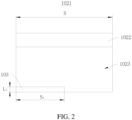
- FIG. 2 is a front view of a negative electrode sheet 1021 with a first insulating layer 103 in an unfolded state provided by some embodiments of the present disclosure
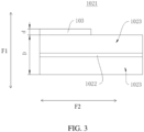
- FIG. 3 is a top view of a negative electrode sheet 1021 of a first type with a first insulating layer 103 provided by some embodiments of the present disclosure
- FIG. 4 is a top view of a negative electrode sheet 1021 of a second type with a first insulating layer 103 provided by some embodiments of the present disclosure.
- the first insulating layer 103 is provided from one end of the negative electrode sheet 1021 in the length direction F2; in FIG.
- FIG. 5 is a front view of a negative electrode sheet 1021 of a further type with a first insulating layer 103 and in an unfolded state provided by some embodiments of the present disclosure, and in this case, the first insulating layer 103 covers all of the edge of the negative electrode sheet 1021 on the side away from the negative electrode tab 1022, thereby separating the positive electrode tab 1024 from all of the edge of the material area 1023 on the side of the negative electrode sheet 1021 away from the negative electrode tab 1022.
- the dimension of the first insulating layer 103 in the width direction of the negative electrode sheet 1021 is L 1 , and L 1 satisfies 0.1 mm ⁇ L 1 ⁇ 50 mm.
- L 1 is less than 0.1 mm, the covered area of the first insulating layer 103 is too small, and a short circuit may not be completely avoided in the process of expansion and extension of the negative electrode sheet 1021;
- L 1 is greater than 50 mm, the covered area of the first insulating layer 103 exceeds the Overhang area too much, which is unfavorable to de-embedding lithium.
- the first insulating layer 103 has a dimension d in the thickness direction F1 of the negative electrode sheet 1021, the dimension d satisfying d ⁇ S ⁇ ⁇ 2 r ⁇ 2 n ⁇ 1 nD n n + 1 ⁇ a ⁇ 2 b
- a dimension d within this range can realize automatic insertion of the electrode assembly into the housing, and a gap for expansion of the electrode sheet and a space for injection of electrolyte in accordance with the design requirements exist between the electrode assembly 102 and the housing 101 after the electrode assembly enters the housing.
- the dimension d of the first insulating layer 103 in the thickness direction of the negative electrode sheet 1021 further satisfies 90 % ⁇ ⁇ r + n d + a + 2 b + 2 n ⁇ 1 2 D 2 ⁇ R 2 ⁇ 98 % where A is the radius (mm) of the housing 101.
- a more optimal range of dimension d can be obtained according to the group margin formula, i.e., Formula (2).
- the value of dimension d in this range can result in a higher energy density on the basis of the technical effect corresponding to Formula (1).
- FIG. 6 is a top view of a negative electrode sheet 1021 of a third type with a first insulating layer 103 provided by some embodiments of the present disclosure.
- the first insulating layer 103 includes multiple first sub-insulating layers 1031, the first sub-insulating layers 1031 are provided on the same side of the negative electrode sheet 1021, and the first sub-insulating layers 1031 are stacked sequentially along the thickness direction of the negative electrode sheet 1021.
- the multiple first sub-insulating layers 1031 may be provided on the same side of the negative pole sheet 1021 by coating.
- FIG. 7 is a top view of a negative electrode sheet 1021 of a fourth type with a first insulating layer 103 provided by some embodiments of the present disclosure
- FIG. 8 is a top view of a negative electrode sheet 1021 of a fifth type with a first insulating layer 103 provided by some embodiments of the present disclosure
- FIG. 9 is a top view of a negative electrode sheet 1021 of a sixth type with a first insulating layer 103 provided by some embodiments of the present disclosure.
- the first insulating layer 103 includes multiple first sub-insulating layers 1031
- the negative electrode sheet 1021 has a first side and a second side which are opposite each other.
- Part of the first sub-insulating layers 1031 are provided on the first side, and the remaining of the first sub-insulating layers 1031 are provided on the second side.
- the first sub-insulating layers 1031 disposed on the same side of the negative electrode sheet 1021 are sequentially stacked along the thickness direction of the negative electrode sheet 1021.
- Part of the first sub-insulating layers 1031 are provided on the first side of the negative electrode sheet 1021, and other part of the first sub-insulating layers 1031 are provided on the second side of the negative electrode sheet 1021, as shown in FIGS. 7 , 8 , and 9 .
- two first sub-insulating layer 1031 are provided on each side of the negative electrode sheet 1021.
- three first sub-insulating layers 1031 are provided on one side of the negative electrode sheet 1021, and two first sub-insulating layers 1031 are provided on the other side of the negative electrode sheet 1021.
- the first sub-insulating layers 1031 are provided on both sides of the negative electrode sheet 1021, and thereby the first insulating layers 103 separate both surfaces of the negative electrode sheet 1021 away from the negative electrode tab 1022 in the thickness direction of the negative electrode sheet 1021 from the positive electrode tab 1024. In this manner, when the separator has been punctured, the material area 1023 on both surfaces of the negative electrode sheet 1021 away from the negative electrode tab 1022 in the thickness direction of the negative electrode sheet 1021 is prevented from directly contacting the positive electrode tab 1024.
- the first sub-insulating layers 1031 may be made of the same insulating material or may be made of different insulating materials.
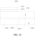
- FIGS. 10 to 13 FIG. 10 is a top view of a negative electrode sheet 1021 of a seventh type with a first insulating layer 103 provided by some embodiments of the present disclosure
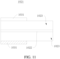
- FIG. 11 is a top view of a negative electrode sheet 1021 of an eighth type with a first insulating layer 103 provided by some embodiments of the present disclosure
- FIG. 12 is a top view of a negative electrode sheet 1021 of a ninth type with a first insulating layer 103 provided by some embodiments of the present disclosure
- FIG. 10 is a top view of a negative electrode sheet 1021 of a seventh type with a first insulating layer 103 provided by some embodiments of the present disclosure
- FIG. 11 is a top view of a negative electrode sheet 1021 of an eighth type with a first insulating layer 103 provided by some embodiments of the present disclosure
- FIG. 12 is a top view
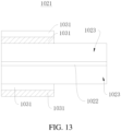
- FIG. 13 is a top view of a negative electrode sheet 1021 of a tenth type with a first insulating layer 103 provided by some embodiments of the present disclosure.
- two first sub-insulating layers 1031 are provided on one side of the negative electrode sheet 1021, and the two first sub-insulating layers 1031 have different insulating materials.
- one first sub-insulating layer 1031 is provided on each of two sides of the negative electrode sheet 1021, and the insulating materials of the first sub-insulating layers 1031 on the two sides of the negative electrode sheet 1021 are different.
- FIG. 10 two first sub-insulating layers 1031 are provided on one side of the negative electrode sheet 1021, and the insulating materials of the first sub-insulating layers 1031 on the two sides of the negative electrode sheet 1021 are different.
- first sub-insulating layers 1031 on two sides of the negative electrode sheet 1021 may be provided in mirror symmetry with respect to the negative electrode sheet 1021; among these first sub-insulating layers 1031 on the two sides, one first sub-insulating layer 1031 directly coated on the negative electrode sheet 1021 utilizes one type of insulating material, and the other first sub-insulating layer 1031 coated on this first sub-insulating layer 1031 utilizes another type of insulating material.
- two first sub-insulating layers 1031 are provided on each of two sides of the negative electrode sheet 1021.
- two first sub-insulating layers 1031 are provided on each of the two sides of the negative electrode sheet 1021.
- One first sub-insulating layer 1031 is directly coated on one side of the negative electrode sheet 1021 and adopts the first insulating material, and the other first sub-insulating layer 1031 is coated on this first sub-insulating layer 1031 and adopts the second insulating material; one first sub-insulating layer 1031 is directly coated on the other side of the negative electrode sheet 1021 and adopts the second insulating material, and another first sub-insulating layer 1031 is coated on this first sub-insulating layer 1031 and adopts the first insulating material.
- the use of different insulating materials in multiple first sub-insulating layers 1031 allows the first insulating layer 103 to obtain the comprehensive performance of the different insulating materials, which facilitates the enhancement of the insulating property between the material area 1023 on the side of the negative electrode sheet 1021 away from the negative electrode tab 1022 and the positive electrode tab 1024.
- the following four groups of negative electrode sheets 1021 are made for control experiments with respect to the setting of the first insulating layer 103.
- the negative electrode sheet 1021 is not provided with the first insulating layer 103.
- the insulating adhesive A is uniformly coated on a portion of the material area which is on one side of the negative electrode sheet 1021 and faces away from the negative electrode tab 1022 to form a first insulating layer 103.
- the first insulating layer 103 includes multiple first sub-insulating layers 1031, the average of the thicknesses d 1 to d i of the first sub-insulating layers 1031 is 5.7 ⁇ m, and the first sub-insulating layers 1031 each have a length S 1 that is equal to the length S of the negative electrode sheet.
- the insulating adhesive A is uniformly coated on portions of the material area which are on two sides of the negative electrode sheet 1021 and face away from the negative electrode tab 1022 to form first insulating layers 103.
- the first sub-insulating layers 1031 coated on both sides of the negative electrode sheet 1021 have thicknesses of 5.5 ⁇ m and 5.7 ⁇ m, and each have a length S 1 that is equal to the length S of the negative electrode sheet.
- the insulating adhesives A and B are uniformly coated on portions of the material area which are on both sides of the negative electrode sheet 1021 and face away from the negative electrode tab 1022 to form first insulating layers 103.
- the first sub-insulating layers 1031 coated on both sides of the negative electrode sheet 1021 have thicknesses of 5.7 ⁇ m and 9.5 ⁇ m, and each have a length S 1 that is equal to the length S of the negative electrode sheet.
- the dimensions of the first sub-insulating layers 1031 in the thickness direction of the negative electrode sheet 1021 are di, d 2 , ..., di, where i is a natural number and i ⁇ 2, and 0.15 ⁇ d 1 : d i ⁇ 1.
- d 1 : d i is limited, thereby ensuring that the thicknesses of the first sub-insulating layers 1031 do not differ much from each other, so that the thickness distribution of the first sub-insulating layers 1031 is as uniform as possible to improve the bonding stability between two adjacent first sub-insulating layers 1031.
- FIG. 14 is a top view of a negative electrode sheet 1021 with a first insulating layer 103 and a second insulating layer 104 provided by some embodiments of the present disclosure.
- an end face in the length direction of the negative electrode sheet 1021 is a first end face, the first end face being disposed at an outer periphery of the electrode assembly 102, and the second insulating layer 104 is provided on the first end face.
- the first end face of the negative electrode sheet 1021 is located at the outer periphery of the electrode assembly 102, and has a large amount of deformation when the negative electrode sheet 1021 expands and extends, causing puncturing the separator and posing a risk of a short circuit. Therefore, the second insulating layer 104 is provided at the first end face, thereby separating the first end face from the positive electrode sheet when the first end face punctures the separator and extends toward the positive electrode sheet, and thus enhancing the stability of the cylindrical battery 10.
- the second insulating layer 104 is also a material layer having insulating properties.
- the insulating materials of the first insulating layer 103 and the second insulating layer 104 have a variety of choices, and the specific raw materials thereof are not limited, and adaptive selection can be made according to the actual application.
- the second insulating layer 104 covers the first end face.
- the second insulating layer 104 covers all of the first end face so that the second insulating layer 104 can separate the positive electrode sheet from the first end face completely.
- the first end face which serves as the cutting surface of the negative electrode sheet 1021, has burrs; when the second insulating layer 104 is provided, the second insulating layer 104 covers the burrs, which can prevent the burrs on the cutting surface from piercing the separator, thereby enhancing the stability of the cylindrical battery 10.
- the second insulating layer 104 has a dimension L 2 in the thickness direction of the negative electrode sheet 1021, the thickness of the negative electrode sheet 1021 is D, and L 2 and D satisfy D ⁇ L 2 ⁇ 50 mm.
- the second insulating layer 104 has a dimension d 0 in the length direction of the negative electrode sheet 1021, the dimension d 0 satisfying 0.001 mm ⁇ d 0 ⁇ 10 mm.
- the second insulating layer 104 cannot cover all of the first end face.
- L 2 is larger than 50 mm, it is unfavorable to the winding of the negative electrode sheet 1021, and it also tends to lead to the detachment of the second insulating layer 104 from the first end face.
- d 0 is smaller than 0.001 mm, the deformation of the first end face when the negative electrode sheet 1021 is wound leads to the breakage of the second insulating layer 104; when the negative electrode sheet 1021 expands and extends, the active substance of the negative electrode sheet 1021 extends from the broken part and punctures the separator.
- d 0 is greater than 10 mm, the protective layer is too thick, and the end of the negative electrode sheet protrudes too much, thereby affecting the size of the gap in the battery receiving cavity after assembly, which then results in a too small gap.
- the positive electrode tab 1024 and the negative electrode tab 1022 are kneaded flat tabs.
- the kneaded flat tabs can effectively reduce the space occupation ratio of electrode tabs, thereby increasing the energy density of the battery.
- the positive electrode tab may be moved closer to an end of the negative electrode sheet away from the negative electrode tab; in this case, when the negative electrode sheet expands and extends, the edge of the material area on the side of the negative electrode sheet 1021 away from the negative electrode tab 1022 punctures the separator, and therefore contacts the positive electrode tab 1024 more easily.
- the first insulating layer is provided on the edge of the material area on the side of the negative electrode sheet 1021 away from the negative electrode tab 1022, which can greatly improve the stability of the cylindrical battery having the kneaded flat tabs.
- the first insulating layer is provided on the edge of the material area on the side of the negative electrode sheet away from the negative electrode tab. In this manner, when the material area on the side of the negative electrode sheet away from the negative electrode tab punctures the separator and extends toward the positive electrode tab, the first insulating layer can separate the material area, which is on the side of the negative electrode sheet away from the negative electrode tab, from the positive electrode tab, thereby avoiding a short circuit caused by contact between the material area on the side of the negative electrode sheet away from the negative electrode tab and the positive electrode tab after the separator is punctured.
- FIG. 15 is a diagram showing the structure of a battery pack 1 provided by some embodiments of the present disclosure.
- Embodiments of the present disclosure also provide a battery pack 1.
- the battery pack 1 includes multiple cylindrical batteries 10, the cylindrical batteries 10 being connected in series or in parallel.
- the battery pack 1 further includes a case 20, the case 20 including a case cover 201 and a case body 202.
- the case cover 201 is capped to the case body 202 to form a closed cylindrical battery mounting cavity.
- the cylindrical batteries 10 are provided in the cylindrical battery mounting cavity.
Landscapes
- Chemical & Material Sciences (AREA)
- Chemical Kinetics & Catalysis (AREA)
- Electrochemistry (AREA)
- General Chemical & Material Sciences (AREA)
- Engineering & Computer Science (AREA)
- Manufacturing & Machinery (AREA)
- Composite Materials (AREA)
- Connection Of Batteries Or Terminals (AREA)
- Cell Separators (AREA)
- Secondary Cells (AREA)
Abstract
Provided are a cylindrical battery (10) and a battery pack (1). The cylindrical battery (10) includes a housing (101), an electrode assembly (102), and a first insulating layer (103). The housing (101) includes a receiving cavity (1014). The electrode assembly (102) is disposed within the receiving cavity (1014). The electrode assembly (102) includes a positive electrode sheet, a separator, and a negative electrode sheet (1021). The positive electrode sheet has a positive electrode tab (1024), the negative electrode sheet (1021) has a negative electrode tab (1022), and the positive electrode tab (1024) and the negative electrode tab (1022) are disposed at two ends of the electrode assembly (102), respectively. The first insulating layer (103) is provided on a surface of the negative electrode sheet (1021) toward the separator and is disposed away from the negative electrode tab (1022).
Description
- The present disclosure relates to the field of battery technology, for example to a cylindrical battery and a battery pack.
- In the long-term cycle of cylindrical batteries, the negative electrode sheets inside the cylindrical batteries will expand and extend, resulting in the separators inside the cylindrical batteries being punctured by the negative electrode sheets.
- In a first aspect, the present disclosure provides a cylindrical battery. The cylindrical battery includes a housing, an electrode assembly, and a first insulating layer. The housing includes a receiving cavity. The electrode assembly is disposed within the receiving cavity. The electrode assembly includes a positive electrode sheet, a separator, and a negative electrode sheet which are stacked and wound. A positive electrode tab of the positive electrode sheet and a negative electrode tab of the negative electrode sheet are disposed at two ends of the electrode assembly, respectively. The first insulating layer is provided on a surface of the negative electrode sheet toward the separator and is disposed at an end, away from the negative electrode tab, of the surface.
- In a second aspect, the present disclosure provides a battery pack. The battery pack includes multiple cylindrical batteries described above, the multiple cylindrical batteries being connected in series or in parallel.
-
-
FIG. 1 is an exploded view of a cylindrical battery provided by some embodiments of the present disclosure. -
FIG. 2 is a front view of a negative electrode sheet with a first insulating layer in an unfolded state provided by some embodiments of the present disclosure. -
FIG. 3 is a top view of a negative electrode sheet of a first type with a first insulating layer provided by some embodiments of the present disclosure. -
FIG. 4 is a top view of a negative electrode sheet of a second type with a first insulating layer provided by some embodiments of the present disclosure. -
FIG. 5 is a front view of a negative electrode sheet of a further type with a first insulating layer and in an unfolded state provided by some embodiments of the present disclosure. -
FIG. 6 is a top view of a negative electrode sheet of a third type with a first insulating layer provided by some embodiments of the present disclosure. -
FIG. 7 is a top view of a negative electrode sheet of a fourth type with a first insulating layer provided by some embodiments of the present disclosure. -
FIG. 8 is a top view of a negative electrode sheet of a fifth type with a first insulating layer provided by some embodiments of the present disclosure. -
FIG. 9 is a top view of a negative electrode sheet of a sixth type with a first insulating layer provided by some embodiments of the present disclosure. -
FIG. 10 is a top view of a negative electrode sheet of a seventh type with a first insulating layer provided by some embodiments of the present disclosure. -
FIG. 11 is a top view of a negative electrode sheet of an eighth type with a first insulating layer provided by some embodiments of the present disclosure. -
FIG. 12 is a top view of a negative electrode sheet of a ninth type with a first insulating layer provided by some embodiments of the present disclosure. -
FIG. 13 is a top view of a negative electrode sheet of a tenth type with a first insulating layer provided by some embodiments of the present disclosure. -
FIG. 14 is a top view of a negative electrode sheet with a first insulating layer and a second insulating layer provided by some embodiments of the present disclosure. -
FIG. 15 is a diagram showing the structure of a battery pack provided by some embodiments of the present disclosure. - Reference numerals are as follows.
Battery pack 1;Cylindrical battery 10;Housing 101;Upper cover 1011;Cylindrical body 1012;Lower cover 1013;Receiving cavity 1014;Electrode assembly 102;Negative electrode sheet 1021;Negative electrode tab 1022;Material area 1023;Positive electrode tab 1024; Firstinsulating layer 103;First sub-insulating layer 1031; Secondinsulating layer 104;Case 20;Case cover 201;Case body 202. - After a separator in a cylindrical battery is punctured, a material area on a side of a negative electrode sheet away from a negative electrode tab is in direct contact with a positive electrode tab, resulting in a short circuit. At present, how to avoid the short circuit caused by the contact between the material area on the side of the negative electrode sheet away from the negative electrode tab and the positive electrode tab after the separator is punctured needs to be solved.
- Embodiments of the present disclosure provide a cylindrical battery and a battery pack for avoiding a short circuit caused by the contact between the material area on the side of the negative electrode sheet away from the negative electrode tab and the positive electrode tab after the separator is punctured.
- Referring to
FIG. 1, FIG. 1 is an exploded view of acylindrical battery 10 provided by some embodiments of the present disclosure. Embodiments of the present disclosure provide acylindrical battery 10, thecylindrical battery 10 including ahousing 101, anelectrode assembly 102, and a firstinsulating layer 103. Thehousing 101 has areceiving cavity 1014. Theelectrode assembly 102 is disposed within thereceiving cavity 1014. Theelectrode assembly 102 includes a positive electrode sheet, a separator, and anegative electrode sheet 1021 which are stacked and wound. Apositive electrode tab 1024 of the positive electrode sheet and anegative electrode tab 1022 of thenegative electrode sheet 1021 are disposed at two ends of theelectrode assembly 102, respectively. The firstinsulating layer 103 is provided on a surface of thenegative electrode sheet 1021 toward the separator, and the firstinsulating layer 103 is disposed at an end of the surface away from thenegative electrode tab 1022. - The
negative electrode sheet 1021 includes a current collector and an active substance layer provided on the current collector, and the area where the active substance layer is located is amaterial area 1023. A surface of the active substance layer away from the current collector is the surface of thenegative electrode sheet 1021 toward the separator. A blank area without the active substance layer is disposed at an end of the surface of the current collector in the width direction of the current collector, and a portion of the current collector in the blank area serves as thenegative electrode tab 1022. The firstinsulating layer 103 is provided on the surface of the active substance layer away from the current collector and is disposed at an end of the surface away from thenegative electrode tab 1022. - The first
insulating layer 103 is a layer of material having insulating properties, which may be provided on thenegative electrode sheet 1021 by coating, or may be provided on thenegative electrode sheet 1021 by adhesion. The first insulatinglayer 103 may include 20% to 40% ceramic, 15% to 60% binder, and 5% to 20% organic solvent by weight. The ceramic includes, but is not limited to, aluminum oxide, boehmite, and zirconium oxide. The binder includes, but is not limited to, polyvinylidene difluoride, polytetrafluoroethylene, and sodium carboxymethyl cellulose. The organic solvent includes, but is not limited to, i-methylpyrrolidone, polyethylene glycol diacrylate, polyethylene glycol dimethacrylate, and a highly insulating adhesive resin. The highly insulating adhesive resin may be a polyvinylidene difluoride-based binder. The polyvinylidene difluoride-based binder is a binder resin formed by preparing a copolymer with organic monomers such as butyl acrylate, acrylonitrile, vinyl acetate, etc., and then dispersing the copolymer with an inorganic filler in an organic solvent. The inorganic filler includes, but is not limited to, potassium persulfate, sodium persulfate, ammonium persulfate, and the like. - For example, the first insulating
layer 103 may be made of any one or more of the insulating adhesives in the table below.Table 1. Information Description Table of Some Insulating Adhesives Serial number Name of insulating adhesive Related information 1 Insulating adhesive A Aluminium oxide, polyvinylidene difluoride, and n-methylpyrrolidone are mixed in a mass ratio of 30:55:15, and an insulating layer slurry with insulating properties is obtained after uniform mixing. 2 Insulating adhesive B Boehmite, polyvinylidene difluoride, and n-methylpyrrolidone are mixed in a mass ratio of 30:55:15, and an insulating layer slurry with insulating properties is obtained after uniform mixing. 3 Insulating adhesive C Aluminium oxide, boehmite, polyvinylidene difluoride, and n-methylpyrrolidone are mixed in a mass ratio of 10:20:55:15, and an insulating layer slurry with insulating properties is obtained after uniform mixing. - In the embodiments, the
material area 1023 is provided on the surface of thenegative electrode sheet 1021 toward the separator, and the firstinsulating layer 103 is provided on the surface of a side of thematerial area 1023 away from thenegative electrode tab 1022. In this manner, during the use of thecylindrical battery 10, in a case where thenegative electrode sheet 1021 expands and extends, which causes thenegative electrode sheet 1021 to puncture the separator, and extend toward thepositive electrode tab 1024, the firstinsulating layer 103 can separate (an edge of) thematerial area 1023, which is on a side of thenegative electrode sheet 1021 away from thenegative electrode tab 1022, from thepositive electrode tab 1024, thereby preventing thematerial area 1023 on the side of thenegative electrode sheet 1021 away from thenegative electrode tab 1022 from directly contacting thepositive electrode tab 1024, thereby avoiding a short circuit caused by direct contact between thematerial area 1023 on the side of thenegative electrode sheet 1021 away from thenegative electrode tab 1022 and thepositive electrode tab 1024, and improving the safety and stability of the battery. - The first
insulating layer 103 has a dimension S1 in the length direction of thenegative electrode sheet 1021, the length of thenegative electrode sheet 1021 is S, and S1 ≤ S. When S1 < S, the firstinsulating layer 103 may be provided at any position along the length of thenegative electrode sheet 1021. In this manner, the firstinsulating layer 103 covers part of the edge of thenegative electrode sheet 1021 on a side away from thenegative electrode tab 1022, thereby separating thepositive electrode tab 1024 from a portion of the edge of thematerial area 1023 on the side of thenegative electrode sheet 1021 away from thenegative electrode tab 1022. As shown inFIGS. 2 to 4 ,FIG. 2 is a front view of anegative electrode sheet 1021 with a firstinsulating layer 103 in an unfolded state provided by some embodiments of the present disclosure,FIG. 3 is a top view of anegative electrode sheet 1021 of a first type with a firstinsulating layer 103 provided by some embodiments of the present disclosure, andFIG. 4 is a top view of anegative electrode sheet 1021 of a second type with afirst insulating layer 103 provided by some embodiments of the present disclosure. InFIGS. 2 and3 , the first insulatinglayer 103 is provided from one end of thenegative electrode sheet 1021 in the length direction F2; inFIG. 4 , the first insulatinglayer 103 is provided from a position that is in the middle of thenegative electrode sheet 1021 in the length direction. When S1 = S, as shown inFIG. 5, FIG. 5 is a front view of anegative electrode sheet 1021 of a further type with a first insulatinglayer 103 and in an unfolded state provided by some embodiments of the present disclosure, and in this case, the first insulatinglayer 103 covers all of the edge of thenegative electrode sheet 1021 on the side away from thenegative electrode tab 1022, thereby separating thepositive electrode tab 1024 from all of the edge of thematerial area 1023 on the side of thenegative electrode sheet 1021 away from thenegative electrode tab 1022. - The dimension of the first insulating
layer 103 in the width direction of thenegative electrode sheet 1021 is L1, and L1 satisfies 0.1 mm ≤ L1 ≤ 50 mm. When L1 is less than 0.1 mm, the covered area of the first insulatinglayer 103 is too small, and a short circuit may not be completely avoided in the process of expansion and extension of thenegative electrode sheet 1021; when L1 is greater than 50 mm, the covered area of the first insulatinglayer 103 exceeds the Overhang area too much, which is unfavorable to de-embedding lithium. - In some embodiments, the first insulating
layer 103 has a dimension d in the thickness direction F1 of thenegative electrode sheet 1021, the dimension d satisfying
- where S is the length (mm) of the
negative electrode sheet 1021; - r is the radius (mm) of a winding needle used for winding to form the electrode assembly;
- a is the thickness (mm) of the positive electrode sheet;
- b is the thickness (mm) of the separator;
- D is the thickness (mm) of the
negative electrode sheet 1021; - n is the number of turns that the negative electrode sheet is wound.
- The formula for calculating the length S2 of the
negative electrode sheet 1021 not provided with the first insulatinglayer 103 is S2 = [(a+2b)(n+1)n+(2n-1)nD+2r]π. Based on this formula, the formula for calculating the length S of thenegative electrode sheet 1021 provided with the first insulatinglayer 103 is known to be S = [(d+a+2b)(n+1)n+(2n-1)nD+2r]π. A transformation of this formula yields:
layer 103 in the thickness direction of thenegative electrode sheet 1021 can then be obtained based on the set length of thenegative electrode sheet 1021. A dimension d within this range can realize automatic insertion of the electrode assembly into the housing, and a gap for expansion of the electrode sheet and a space for injection of electrolyte in accordance with the design requirements exist between theelectrode assembly 102 and thehousing 101 after the electrode assembly enters the housing. - In some embodiments, the dimension d of the first insulating
layer 103 in the thickness direction of thenegative electrode sheet 1021 further satisfies
where A is the radius (mm) of thehousing 101. - Based on Formula (1), a more optimal range of dimension d can be obtained according to the group margin formula, i.e., Formula (2). The value of dimension d in this range can result in a higher energy density on the basis of the technical effect corresponding to Formula (1).
- Referring to
FIG. 6, FIG. 6 is a top view of anegative electrode sheet 1021 of a third type with a first insulatinglayer 103 provided by some embodiments of the present disclosure. In some embodiments, the first insulatinglayer 103 includes multiple firstsub-insulating layers 1031, the firstsub-insulating layers 1031 are provided on the same side of thenegative electrode sheet 1021, and the firstsub-insulating layers 1031 are stacked sequentially along the thickness direction of thenegative electrode sheet 1021. - Along a direction approaching the
negative electrode sheet 1021, the firstsub-insulating layers 1031 have dimensions (i.e., thicknesses) in the thickness direction of thenegative electrode sheet 1021 in the order of di, d2, ..., di, where i is a natural number and i ≥ 2, and ∑ di = d. It is to be understood that, based on the thickness d of the first insulatinglayer 103, the number of the firstsub-insulating layers 1031 may be designed, e.g., i = 2, i = 3, i = 4 or i = 5, such that the value of ∑ di satisfies the aforementioned Formula (1) or Formula (2). - In the embodiments shown in
FIG. 6 , the multiple firstsub-insulating layers 1031 may be provided on the same side of thenegative pole sheet 1021 by coating. As a result, it can be advantageous to control the thickness of the first insulatinglayer 103 and also increase the insulating property of the first insulatinglayer 103, thereby making the internal resistance between thematerial area 1023 on the side of thenegative electrode sheet 1021 away from thenegative electrode tab 1022 and thepositive electrode tab 1024 larger, and enhancing the insulating property between thematerial area 1023 on the side of thenegative electrode sheet 1021 away from thenegative electrode tab 1022 and thepositive electrode tab 1024. - Referring to
FIGS. 7 to 9 ,FIG. 7 is a top view of anegative electrode sheet 1021 of a fourth type with a first insulatinglayer 103 provided by some embodiments of the present disclosure,FIG. 8 is a top view of anegative electrode sheet 1021 of a fifth type with a first insulatinglayer 103 provided by some embodiments of the present disclosure, andFIG. 9 is a top view of anegative electrode sheet 1021 of a sixth type with a first insulatinglayer 103 provided by some embodiments of the present disclosure. In some embodiments, the first insulatinglayer 103 includes multiple firstsub-insulating layers 1031, and thenegative electrode sheet 1021 has a first side and a second side which are opposite each other. Part of the firstsub-insulating layers 1031 are provided on the first side, and the remaining of the firstsub-insulating layers 1031 are provided on the second side. The firstsub-insulating layers 1031 disposed on the same side of thenegative electrode sheet 1021 are sequentially stacked along the thickness direction of thenegative electrode sheet 1021. - Part of the first
sub-insulating layers 1031 are provided on the first side of thenegative electrode sheet 1021, and other part of the firstsub-insulating layers 1031 are provided on the second side of thenegative electrode sheet 1021, as shown inFIGS. 7 ,8 , and9 . InFIG. 7 , onefirst sub-insulating layer 1031 is provided on each side of thenegative electrode sheet 1021, and the two firstsub-insulating layers 1031 have dimensions, namely d1 and d2, in the thickness direction of thenegative electrode sheet 1021, where d1 + d2 = d. InFIG. 8 , twofirst sub-insulating layer 1031 are provided on each side of thenegative electrode sheet 1021. From the first side to the second side of thenegative electrode sheet 1021, the dimensions of the firstsub-insulating layers 1031 in the thickness direction of thenegative electrode sheet 1021 are d1, d2, d3 and d4, where d1 + d2 +d3 + d4 = d. InFIG. 9 , three firstsub-insulating layers 1031 are provided on one side of thenegative electrode sheet 1021, and two firstsub-insulating layers 1031 are provided on the other side of thenegative electrode sheet 1021. From the first side to the second side of thenegative electrode sheet 1021, the dimensions of the firstsub-insulating layers 1031 in the thickness direction of thenegative electrode sheet 1021 are d1, d2, d3, d4 and d5, where d1 + d2 + d3 + d4 +d5 = d. - The first
sub-insulating layers 1031 are provided on both sides of thenegative electrode sheet 1021, and thereby the first insulatinglayers 103 separate both surfaces of thenegative electrode sheet 1021 away from thenegative electrode tab 1022 in the thickness direction of thenegative electrode sheet 1021 from thepositive electrode tab 1024. In this manner, when the separator has been punctured, thematerial area 1023 on both surfaces of thenegative electrode sheet 1021 away from thenegative electrode tab 1022 in the thickness direction of thenegative electrode sheet 1021 is prevented from directly contacting thepositive electrode tab 1024. - When there are multiple first
sub-insulating layers 1031, the firstsub-insulating layers 1031 may be made of the same insulating material or may be made of different insulating materials. As shown inFIGS. 10 to 13 ,FIG. 10 is a top view of anegative electrode sheet 1021 of a seventh type with a first insulatinglayer 103 provided by some embodiments of the present disclosure,FIG. 11 is a top view of anegative electrode sheet 1021 of an eighth type with a first insulatinglayer 103 provided by some embodiments of the present disclosure,FIG. 12 is a top view of anegative electrode sheet 1021 of a ninth type with a first insulatinglayer 103 provided by some embodiments of the present disclosure, andFIG. 13 is a top view of anegative electrode sheet 1021 of a tenth type with a first insulatinglayer 103 provided by some embodiments of the present disclosure. InFIG. 10 , two firstsub-insulating layers 1031 are provided on one side of thenegative electrode sheet 1021, and the two firstsub-insulating layers 1031 have different insulating materials. InFIG. 11 , onefirst sub-insulating layer 1031 is provided on each of two sides of thenegative electrode sheet 1021, and the insulating materials of the firstsub-insulating layers 1031 on the two sides of thenegative electrode sheet 1021 are different. InFIG. 12 , firstsub-insulating layers 1031 on two sides of thenegative electrode sheet 1021 may be provided in mirror symmetry with respect to thenegative electrode sheet 1021; among these firstsub-insulating layers 1031 on the two sides, onefirst sub-insulating layer 1031 directly coated on thenegative electrode sheet 1021 utilizes one type of insulating material, and the other firstsub-insulating layer 1031 coated on this firstsub-insulating layer 1031 utilizes another type of insulating material. InFIG. 13 , two firstsub-insulating layers 1031 are provided on each of two sides of thenegative electrode sheet 1021. For example, two firstsub-insulating layers 1031 are provided on each of the two sides of thenegative electrode sheet 1021. Onefirst sub-insulating layer 1031 is directly coated on one side of thenegative electrode sheet 1021 and adopts the first insulating material, and the other firstsub-insulating layer 1031 is coated on this firstsub-insulating layer 1031 and adopts the second insulating material; onefirst sub-insulating layer 1031 is directly coated on the other side of thenegative electrode sheet 1021 and adopts the second insulating material, and another firstsub-insulating layer 1031 is coated on this firstsub-insulating layer 1031 and adopts the first insulating material. - The use of different insulating materials in multiple first
sub-insulating layers 1031 allows the first insulatinglayer 103 to obtain the comprehensive performance of the different insulating materials, which facilitates the enhancement of the insulating property between thematerial area 1023 on the side of thenegative electrode sheet 1021 away from thenegative electrode tab 1022 and thepositive electrode tab 1024. - According to the aforementioned information description table of some insulating adhesives, the following four groups of
negative electrode sheets 1021 are made for control experiments with respect to the setting of the first insulatinglayer 103. - Group I: The
negative electrode sheet 1021 is not provided with the first insulatinglayer 103. - Group II: The insulating adhesive A is uniformly coated on a portion of the material area which is on one side of the
negative electrode sheet 1021 and faces away from thenegative electrode tab 1022 to form a first insulatinglayer 103. The first insulatinglayer 103 includes multiple firstsub-insulating layers 1031, the average of the thicknesses d1 to di of the firstsub-insulating layers 1031 is 5.7 µm, and the firstsub-insulating layers 1031 each have a length S1 that is equal to the length S of the negative electrode sheet. - Group III: The insulating adhesive A is uniformly coated on portions of the material area which are on two sides of the
negative electrode sheet 1021 and face away from thenegative electrode tab 1022 to form first insulatinglayers 103. The firstsub-insulating layers 1031 coated on both sides of thenegative electrode sheet 1021 have thicknesses of 5.5 µm and 5.7 µm, and each have a length S1 that is equal to the length S of the negative electrode sheet. - Group IV: The insulating adhesives A and B are uniformly coated on portions of the material area which are on both sides of the
negative electrode sheet 1021 and face away from thenegative electrode tab 1022 to form first insulatinglayers 103. The firstsub-insulating layers 1031 coated on both sides of thenegative electrode sheet 1021 have thicknesses of 5.7 µm and 9.5 µm, and each have a length S1 that is equal to the length S of the negative electrode sheet. - For these four groups of
negative electrode sheets 1021, the internal resistance of a side of thenegative electrode sheet 1021 away from thenegative electrode tab 1022 is detected using the four-probe method to obtain the following internal resistance data table.Table 2. Measurement Table of the Internal Resistances of the Four Groups of Negative Electrode Sheets 1021Experimental group Internal resistance/mΩ Group I 11.3 Group II 12.4 Group III 13.7 Group IV 16.4 - As can be seen from Table 2, in cases where the first insulating
layer 103 is thicker, and the insulating adhesive is coated on each side of thenegative electrode sheet 1021, the internal resistance of the correspondingnegative electrode sheet 1021 is higher. - In some embodiments, in a case where there are multiple first
sub-insulating layers 1031, from one side to the other side of thenegative electrode sheet 1021, the dimensions of the firstsub-insulating layers 1031 in the thickness direction of thenegative electrode sheet 1021 are di, d2, ..., di, where i is a natural number and i ≥ 2, and 0.15 < d1: di ≤ 1. - d1 : di is limited, thereby ensuring that the thicknesses of the first
sub-insulating layers 1031 do not differ much from each other, so that the thickness distribution of the firstsub-insulating layers 1031 is as uniform as possible to improve the bonding stability between two adjacent first sub-insulating layers 1031. Optionally, 0.2 < d1 : di ≤ 0.75. - Referring to
FIG. 14, FIG. 14 is a top view of anegative electrode sheet 1021 with a first insulatinglayer 103 and a second insulatinglayer 104 provided by some embodiments of the present disclosure. In some embodiments, an end face in the length direction of thenegative electrode sheet 1021 is a first end face, the first end face being disposed at an outer periphery of theelectrode assembly 102, and the second insulatinglayer 104 is provided on the first end face. - The first end face of the
negative electrode sheet 1021 is located at the outer periphery of theelectrode assembly 102, and has a large amount of deformation when thenegative electrode sheet 1021 expands and extends, causing puncturing the separator and posing a risk of a short circuit. Therefore, the second insulatinglayer 104 is provided at the first end face, thereby separating the first end face from the positive electrode sheet when the first end face punctures the separator and extends toward the positive electrode sheet, and thus enhancing the stability of thecylindrical battery 10. - Like the first insulating
layer 103, the second insulatinglayer 104 is also a material layer having insulating properties. The insulating materials of the first insulatinglayer 103 and the second insulatinglayer 104 have a variety of choices, and the specific raw materials thereof are not limited, and adaptive selection can be made according to the actual application. - In some embodiments, the second insulating
layer 104 covers the first end face. The secondinsulating layer 104 covers all of the first end face so that the second insulatinglayer 104 can separate the positive electrode sheet from the first end face completely. In addition, when thenegative electrode sheet 1021 is cut, the first end face, which serves as the cutting surface of thenegative electrode sheet 1021, has burrs; when the second insulatinglayer 104 is provided, the second insulatinglayer 104 covers the burrs, which can prevent the burrs on the cutting surface from piercing the separator, thereby enhancing the stability of thecylindrical battery 10. - In some embodiments, the second insulating
layer 104 has a dimension L2 in the thickness direction of thenegative electrode sheet 1021, the thickness of thenegative electrode sheet 1021 is D, and L2 and D satisfy D ≤ L2 ≤ 50 mm. The secondinsulating layer 104 has a dimension d0 in the length direction of thenegative electrode sheet 1021, the dimension d0 satisfying 0.001 mm ≤ d0 ≤ 10 mm. - When L2 is smaller than the thickness D of the
negative electrode sheet 1021, the second insulatinglayer 104 cannot cover all of the first end face. When L2 is larger than 50 mm, it is unfavorable to the winding of thenegative electrode sheet 1021, and it also tends to lead to the detachment of the second insulatinglayer 104 from the first end face. When d0 is smaller than 0.001 mm, the deformation of the first end face when thenegative electrode sheet 1021 is wound leads to the breakage of the second insulatinglayer 104; when thenegative electrode sheet 1021 expands and extends, the active substance of thenegative electrode sheet 1021 extends from the broken part and punctures the separator. When d0 is greater than 10 mm, the protective layer is too thick, and the end of the negative electrode sheet protrudes too much, thereby affecting the size of the gap in the battery receiving cavity after assembly, which then results in a too small gap. - For example, D ≤ L2 ≤ 30 mm and 0.01 mm ≤ d0 ≤ 1 mm.
- In some embodiments, the
positive electrode tab 1024 and thenegative electrode tab 1022 are kneaded flat tabs. The kneaded flat tabs can effectively reduce the space occupation ratio of electrode tabs, thereby increasing the energy density of the battery. However, when the tabs are kneaded flat, the positive electrode tab may be moved closer to an end of the negative electrode sheet away from the negative electrode tab; in this case, when the negative electrode sheet expands and extends, the edge of the material area on the side of thenegative electrode sheet 1021 away from thenegative electrode tab 1022 punctures the separator, and therefore contacts thepositive electrode tab 1024 more easily. In the embodiments, the first insulating layer is provided on the edge of the material area on the side of thenegative electrode sheet 1021 away from thenegative electrode tab 1022, which can greatly improve the stability of the cylindrical battery having the kneaded flat tabs. - In the embodiments of the present disclosure, the first insulating layer is provided on the edge of the material area on the side of the negative electrode sheet away from the negative electrode tab. In this manner, when the material area on the side of the negative electrode sheet away from the negative electrode tab punctures the separator and extends toward the positive electrode tab, the first insulating layer can separate the material area, which is on the side of the negative electrode sheet away from the negative electrode tab, from the positive electrode tab, thereby avoiding a short circuit caused by contact between the material area on the side of the negative electrode sheet away from the negative electrode tab and the positive electrode tab after the separator is punctured.
- As shown in
FIG. 15, FIG. 15 is a diagram showing the structure of abattery pack 1 provided by some embodiments of the present disclosure. Embodiments of the present disclosure also provide abattery pack 1. Thebattery pack 1 includes multiplecylindrical batteries 10, thecylindrical batteries 10 being connected in series or in parallel. Thebattery pack 1 further includes acase 20, thecase 20 including acase cover 201 and acase body 202. Thecase cover 201 is capped to thecase body 202 to form a closed cylindrical battery mounting cavity. Thecylindrical batteries 10 are provided in the cylindrical battery mounting cavity.
Claims (11)
- A cylindrical battery, characterized by comprising:a housing (101) having a receiving cavity (1014);an electrode assembly (102) disposed within the receiving cavity (1014), wherein the electrode assembly (102) comprises a positive electrode sheet, a separator, and a negative electrode sheet (1021) which are stacked and wound, and a positive electrode tab (1024) of the positive electrode sheet and a negative electrode tab (1022) of the negative electrode sheet (1021) are disposed at two ends of the electrode assembly (102), respectively; anda first insulating layer (103) provided on a surface of the negative electrode sheet (1021) toward the separator and disposed at an end, away from the negative electrode tab (1022), of the surface.
- The cylindrical battery according to claim 1, wherein the first insulating layer (103) has a dimension d in a thickness direction of the negative electrode sheet (1021), the dimension d satisfying
 wherein S is a length (mm) of the negative electrode sheet (1021);r is a radius (mm) of a winding needle used for winding to form the electrode assembly (102); a is a thickness (mm) of the positive electrode sheet;b is a thickness (mm) of the separator;D is a thickness (mm) of the negative electrode sheet (1021); andn is a number of turns that the negative electrode sheet (1021) is wound.
 - The cylindrical battery according to claim 2, wherein the dimension d of the first insulating layer (103) in the thickness direction of the negative electrode sheet (1021) further satisfies

- The cylindrical battery according to claim 1, wherein the first insulating layer (103) comprises a plurality of first sub-insulating layers (1031), the plurality of first sub-insulating layers (1031) are provided on a same side of the negative electrode sheet (1021), and the plurality of first sub-insulating layers (1031) are stacked sequentially along a thickness direction of the negative electrode sheet (1021).
- The cylindrical battery according to any one of claims 1 to 3, wherein the first insulating layer (103) comprises a plurality of first sub-insulating layers (1031);the negative electrode sheet (1021) has a first side and a second side which are opposite each other, part of the plurality of first sub-insulating layers (1031) are provided on the first side, and the remaining of the plurality of first sub-insulating layers (1031) are provided on the second side; andthe part of first sub-insulating layers (1031) or the remaining of first sub-insulating layers (1031) are sequentially stacked along a thickness direction of the negative electrode sheet (1021).
- The cylindrical battery according to claim 4 or 5, wherein from one side of the negative electrode sheet (1021) to the other side of the negative electrode sheet (1021), dimensions of the plurality of first sub-insulating layers (1031) in the thickness direction of the negative electrode sheet (1021) are di, d2, ..., di, the dimensions satisfying 0.15 < d1: di ≤ 1, wherein i is a natural number and i ≥ 2.
- The cylindrical battery according to any one of claims 1 to 6, wherein an end face of the negative electrode sheet (1021) in a length direction of the negative electrode sheet (1021) is a first end face, the first end face being disposed at an outer periphery of the electrode assembly (102), and a second insulating layer (104) is provided on the first end face.
- The cylindrical battery according to claim 7, wherein the second insulating layer (104) covers the first end face.
- The cylindrical battery according to claim 7 or 8, wherein the second insulating layer (104) has a dimension L2 in a thickness direction of the negative electrode sheet (1021), a thickness of the negative electrode sheet (1021) is D, and L2 and D satisfy D ≤ L2 ≤ 50 mm; and
the second insulating layer (104) has a dimension d0 in the length direction of the negative electrode sheet (1021), the dimension d0 satisfying 0.001 mm ≤ d0 ≤ 10 mm. - The cylindrical battery according to any one of claims 1 to 9, wherein the positive electrode tab (1024) and the negative electrode tab (1022) are kneaded flat tab.
- A battery pack, characterized by comprising a plurality of cylindrical batteries (10) according to any one of claims 1 to 10, the plurality of cylindrical batteries (10) being connected in series or in parallel.
Applications Claiming Priority (2)
| Application Number | Priority Date | Filing Date | Title |
|---|---|---|---|
| CN202311201240.3A CN117154356A (en) | 2023-09-15 | 2023-09-15 | A cylindrical battery and battery pack |
| PCT/CN2024/107879 WO2025055569A1 (en) | 2023-09-15 | 2024-07-26 | Cylindrical battery and battery pack |
Publications (1)
| Publication Number | Publication Date |
|---|---|
| EP4525085A1 true EP4525085A1 (en) | 2025-03-19 |
Family
ID=92800104
Family Applications (1)
| Application Number | Title | Priority Date | Filing Date |
|---|---|---|---|
| EP24200319.2A Pending EP4525085A1 (en) | 2023-09-15 | 2024-09-13 | Cylindrical battery and battery pack |
Country Status (4)
| Country | Link |
|---|---|
| US (1) | US20250096441A1 (en) |
| EP (1) | EP4525085A1 (en) |
| JP (1) | JP2025043339A (en) |
| KR (1) | KR20250040563A (en) |
Citations (4)
| Publication number | Priority date | Publication date | Assignee | Title |
|---|---|---|---|---|
| JP2016219382A (en) * | 2015-05-26 | 2016-12-22 | 株式会社東芝 | battery |
| WO2023013933A1 (en) * | 2021-08-05 | 2023-02-09 | 주식회사 엘지에너지솔루션 | Electrode assembly, cylindrical battery cell, and battery pack and vehicle including same |
| CN115911256A (en) * | 2022-11-04 | 2023-04-04 | 厦门新能达科技有限公司 | Cylindrical battery and electrical device containing it |
| WO2023085893A1 (en) * | 2021-11-12 | 2023-05-19 | 주식회사 엘지에너지솔루션 | Separator, electrode assembly, cylindrical battery cell, and battery pack and vehicle including same |
Family Cites Families (2)
| Publication number | Priority date | Publication date | Assignee | Title |
|---|---|---|---|---|
| EP4468445B1 (en) * | 2022-01-19 | 2026-03-04 | LG Energy Solution, Ltd. | Electrode assembly having short-circuit prevention structure |
| CN218827324U (en) * | 2022-10-21 | 2023-04-07 | 宁德时代新能源科技股份有限公司 | Electrode assembly, battery cell, battery and power consumption device |
-
2024
- 2024-09-13 EP EP24200319.2A patent/EP4525085A1/en active Pending
- 2024-09-14 US US18/885,638 patent/US20250096441A1/en active Pending
- 2024-09-17 JP JP2024160356A patent/JP2025043339A/en active Pending
- 2024-09-19 KR KR1020240126710A patent/KR20250040563A/en active Pending
Patent Citations (4)
| Publication number | Priority date | Publication date | Assignee | Title |
|---|---|---|---|---|
| JP2016219382A (en) * | 2015-05-26 | 2016-12-22 | 株式会社東芝 | battery |
| WO2023013933A1 (en) * | 2021-08-05 | 2023-02-09 | 주식회사 엘지에너지솔루션 | Electrode assembly, cylindrical battery cell, and battery pack and vehicle including same |
| WO2023085893A1 (en) * | 2021-11-12 | 2023-05-19 | 주식회사 엘지에너지솔루션 | Separator, electrode assembly, cylindrical battery cell, and battery pack and vehicle including same |
| CN115911256A (en) * | 2022-11-04 | 2023-04-04 | 厦门新能达科技有限公司 | Cylindrical battery and electrical device containing it |
Also Published As
| Publication number | Publication date |
|---|---|
| KR20250040563A (en) | 2025-03-24 |
| US20250096441A1 (en) | 2025-03-20 |
| JP2025043339A (en) | 2025-03-28 |
Similar Documents
| Publication | Publication Date | Title |
|---|---|---|
| EP1683226B1 (en) | Lithium ion secondary battery | |
| EP3648202A1 (en) | Electrode sheet, battery cell and battery | |
| EP0975041B1 (en) | Flat cells | |
| CN115764179B (en) | Batteries and electrical equipment | |
| CN213150818U (en) | Battery tab rubberizing structure | |
| CN115986329A (en) | Electrode assembly, cylindrical battery cell, battery pack including same, and automobile | |
| KR20040016442A (en) | Non-aqueous electrolytic battery and its manufacturing method | |
| WO2025055569A1 (en) | Cylindrical battery and battery pack | |
| CN213520076U (en) | A lithium-ion battery | |
| CN218918943U (en) | Electrode plate, battery cell and battery | |
| EP4354575A1 (en) | Lithium ion battery and separator thereof | |
| CN116315509A (en) | A kind of electric core and preparation method thereof and lithium ion battery | |
| JP4443178B2 (en) | Laminate battery manufacturing method and laminate battery manufacturing mold | |
| EP4503321A1 (en) | Electrode sheet and battery | |
| WO2024138805A1 (en) | Electrode pole piece, preparation method therefor, and lithium ion battery | |
| CN109494413A (en) | A kind of soft bag lithium ionic cell and preparation method thereof | |
| EP4525085A1 (en) | Cylindrical battery and battery pack | |
| EP4704243A2 (en) | Secondary battery and electronic apparatus | |
| EP4376204A1 (en) | Battery cover plate and power battery | |
| WO2026026839A1 (en) | Secondary battery and electronic device | |
| US20250023057A1 (en) | Electrochemical device, module and electronic device | |
| CN219832969U (en) | Electrode plate and battery | |
| CN209461573U (en) | A kind of positive plate with tab and the polymer Li-ion battery containing the positive plate | |
| CN219591471U (en) | Battery cell and soft package battery | |
| JP2004247209A (en) | Stacked battery |
Legal Events
| Date | Code | Title | Description |
|---|---|---|---|
| PUAI | Public reference made under article 153(3) epc to a published international application that has entered the european phase |
Free format text: ORIGINAL CODE: 0009012 |
|
| STAA | Information on the status of an ep patent application or granted ep patent |
Free format text: STATUS: REQUEST FOR EXAMINATION WAS MADE |
|
| 17P | Request for examination filed |
Effective date: 20240913 |
|
| AK | Designated contracting states |
Kind code of ref document: A1 Designated state(s): AL AT BE BG CH CY CZ DE DK EE ES FI FR GB GR HR HU IE IS IT LI LT LU LV MC ME MK MT NL NO PL PT RO RS SE SI SK SM TR |