EP4525067A1 - Electrode for secondary battery, method for manufacturing same, and secondary battery including same - Google Patents
Electrode for secondary battery, method for manufacturing same, and secondary battery including same Download PDFInfo
- Publication number
- EP4525067A1 EP4525067A1 EP23850312.2A EP23850312A EP4525067A1 EP 4525067 A1 EP4525067 A1 EP 4525067A1 EP 23850312 A EP23850312 A EP 23850312A EP 4525067 A1 EP4525067 A1 EP 4525067A1
- Authority
- EP
- European Patent Office
- Prior art keywords
- electrode
- side part
- secondary battery
- electrode slurry
- slurry
- Prior art date
- Legal status (The legal status is an assumption and is not a legal conclusion. Google has not performed a legal analysis and makes no representation as to the accuracy of the status listed.)
- Pending
Links
Images


Classifications
-
- H—ELECTRICITY
- H01—ELECTRIC ELEMENTS
- H01M—PROCESSES OR MEANS, e.g. BATTERIES, FOR THE DIRECT CONVERSION OF CHEMICAL ENERGY INTO ELECTRICAL ENERGY
- H01M4/00—Electrodes
- H01M4/02—Electrodes composed of, or comprising, active material
- H01M4/04—Processes of manufacture in general
-
- H—ELECTRICITY
- H01—ELECTRIC ELEMENTS
- H01M—PROCESSES OR MEANS, e.g. BATTERIES, FOR THE DIRECT CONVERSION OF CHEMICAL ENERGY INTO ELECTRICAL ENERGY
- H01M4/00—Electrodes
- H01M4/02—Electrodes composed of, or comprising, active material
- H01M4/04—Processes of manufacture in general
- H01M4/0402—Methods of deposition of the material
- H01M4/0404—Methods of deposition of the material by coating on electrode collectors
-
- H—ELECTRICITY
- H01—ELECTRIC ELEMENTS
- H01M—PROCESSES OR MEANS, e.g. BATTERIES, FOR THE DIRECT CONVERSION OF CHEMICAL ENERGY INTO ELECTRICAL ENERGY
- H01M10/00—Secondary cells; Manufacture thereof
- H01M10/05—Accumulators with non-aqueous electrolyte
- H01M10/052—Li-accumulators
- H01M10/0525—Rocking-chair batteries, i.e. batteries with lithium insertion or intercalation in both electrodes; Lithium-ion batteries
-
- H—ELECTRICITY
- H01—ELECTRIC ELEMENTS
- H01M—PROCESSES OR MEANS, e.g. BATTERIES, FOR THE DIRECT CONVERSION OF CHEMICAL ENERGY INTO ELECTRICAL ENERGY
- H01M4/00—Electrodes
- H01M4/02—Electrodes composed of, or comprising, active material
- H01M4/04—Processes of manufacture in general
- H01M4/0402—Methods of deposition of the material
- H01M4/0409—Methods of deposition of the material by a doctor blade method, slip-casting or roller coating
-
- H—ELECTRICITY
- H01—ELECTRIC ELEMENTS
- H01M—PROCESSES OR MEANS, e.g. BATTERIES, FOR THE DIRECT CONVERSION OF CHEMICAL ENERGY INTO ELECTRICAL ENERGY
- H01M4/00—Electrodes
- H01M4/02—Electrodes composed of, or comprising, active material
- H01M4/13—Electrodes for accumulators with non-aqueous electrolyte, e.g. for lithium-accumulators; Processes of manufacture thereof
-
- H—ELECTRICITY
- H01—ELECTRIC ELEMENTS
- H01M—PROCESSES OR MEANS, e.g. BATTERIES, FOR THE DIRECT CONVERSION OF CHEMICAL ENERGY INTO ELECTRICAL ENERGY
- H01M4/00—Electrodes
- H01M4/02—Electrodes composed of, or comprising, active material
- H01M4/13—Electrodes for accumulators with non-aqueous electrolyte, e.g. for lithium-accumulators; Processes of manufacture thereof
- H01M4/139—Processes of manufacture
-
- H—ELECTRICITY
- H01—ELECTRIC ELEMENTS
- H01M—PROCESSES OR MEANS, e.g. BATTERIES, FOR THE DIRECT CONVERSION OF CHEMICAL ENERGY INTO ELECTRICAL ENERGY
- H01M4/00—Electrodes
- H01M4/02—Electrodes composed of, or comprising, active material
- H01M2004/021—Physical characteristics, e.g. porosity, surface area
-
- Y—GENERAL TAGGING OF NEW TECHNOLOGICAL DEVELOPMENTS; GENERAL TAGGING OF CROSS-SECTIONAL TECHNOLOGIES SPANNING OVER SEVERAL SECTIONS OF THE IPC; TECHNICAL SUBJECTS COVERED BY FORMER USPC CROSS-REFERENCE ART COLLECTIONS [XRACs] AND DIGESTS
- Y02—TECHNOLOGIES OR APPLICATIONS FOR MITIGATION OR ADAPTATION AGAINST CLIMATE CHANGE
- Y02E—REDUCTION OF GREENHOUSE GAS [GHG] EMISSIONS, RELATED TO ENERGY GENERATION, TRANSMISSION OR DISTRIBUTION
- Y02E60/00—Enabling technologies; Technologies with a potential or indirect contribution to GHG emissions mitigation
- Y02E60/10—Energy storage using batteries
Definitions
- the present disclosure relates to an electrode for a secondary battery, a method for manufacturing the same, and a secondary battery including the same.
- an electrode for a lithium secondary battery is manufactured by applying an electrode slurry prepared by mixing and dispersing an electrode active material, a conductive material, and a binder in a solvent on a current collector and then drying.
- an electrode slurry prepared by mixing and dispersing an electrode active material, a conductive material, and a binder in a solvent on a current collector and then drying.
- a side part based on a width direction is dried first, which causes a difference in drying rates between a center part and a side part based on the width direction of the applied electrode slurry.
- surface quality problems such as a rise of the side part of an electrode or formation of cracks or wrinkles on the surface of the electrode side part may occur.
- a lithium salt is precipitated by cracks or wrinkles occurring on the surface of the electrode, which may deteriorate battery life characteristics.
- Patent Document 1 Korean Patent Laid-Open Publication No. 10-2017-0100377 (publication date: September 4, 2017 )
- An object of the present disclosure is to provide an electrode for a secondary battery which may solve problems in which a side part of an electrode rises or cracks or wrinkles are formed on the surface of the side part of an electrode by a drying process during a process for manufacturing an electrode, a method for manufacturing the same, and a secondary battery including the same.
- Another object of the present disclosure is to provide an electrode for a secondary battery which may improve surface quality of an electrode and increase productivity while simultaneously improving life characteristics of a battery, and a method for manufacturing the same, by solving the above problems.
- the electrode for a secondary battery of the present disclosure may be widely applied to electric vehicles, battery charging stations, and other green technology fields such as solar power generations and wind power generations using batteries.
- an electrode for a secondary battery of the present disclosure may be used in eco-friendly electric vehicles, hybrid vehicles, and the like for preventing climate change by suppressing air pollution and greenhouse gas emissions.
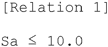
- an electrode for a secondary battery includes: a current collector; and an electrode active material layer placed on at least one surface of the current collector, wherein the following Relation 1 is satisfied: Sa ⁇ 10.0 wherein Sa is an average surface roughness value ( ⁇ m) of a side part based on a width direction of the electrode active material layer.
- the number of cracks per unit area of 10 cm 2 of the side part based on the width direction of the electrode active material layer may be less than 5.
- a maximum long diameter of the crack in the side part based on the width direction of the electrode active material layer may be less than 100 mm.
- a method for manufacturing an electrode for a secondary battery includes: a) applying an electrode slurry on at least one surface of a current collector; and b) drying the applied electrode slurry, wherein the following Relation 2 is satisfied: We / Wc ⁇ 1 wherein Wc is a solid content of the electrode slurry applied to a center part, and We is a solid content of the electrode slurry applied to a side part, based on a width direction of the applied electrode slurry.
- the We/Wc value of Relation 2 may be 0.8 or more and less than 1.
- the process a) may include:
- the process a2) may be performed by:
- a width of the side part may be 15% or less based on an overall width length of the applied electrode slurry.
- the electrode slurries applied to the center part and the side part may have the same composition.
- the electrode slurry applied to the center part may have a viscosity Vc of 1,000 to 10,000 cP.
- the electrode slurry applied to the side part may have a viscosity Ve of 1,000 to 6,000 cP.
- a secondary battery includes: the electrode according to the example embodiment described above; a separator; and an electrolyte solution.
- a width of the side part 12 may refer to a section of 15% or less of the overall width length of the electrode coated part 10, when one electrode slurry is uniformly applied on one surface of a current collector.
- a width of the side part 12 in an example embodiment may be 1 to 20 mm, or 5 to 20 mm in a specific example embodiment, but is not limited thereto.
- thermal conductivity of a current collector may act as an additional heat source so that drying may be accelerated to cause a difference in drying rates between the center part and the side part based on the width direction. Due to the difference in the drying rates, problems in which the side part of the electrode rises or cracks or winkles are formed on the surface of the electrode side part may arise after drying, as shown in FIG. 4 .
- an electrode for a secondary battery including: a current collector; and an electrode active material layer placed on at least one surface of the current collector, wherein the following Relation 1 is satisfied, may be provided: Sa ⁇ 10.0 wherein Sa is an average surface roughness value ( ⁇ m) of a side part based on a width direction of the electrode active material layer.
- the average surface roughness Sa value may be 10.0 ⁇ m or less, 8.0 ⁇ m or less, 6.0 ⁇ m or less, 5.0 ⁇ m or less and more than 0 um, 1.0 ⁇ m or more, 1.5 ⁇ m or more, or a value between the numerical values.
- the average surface roughness Sa value may be more than 0 ⁇ m and 10.0 ⁇ m or less, more than 0 ⁇ m and 8.0 ⁇ m or less, more than 0 ⁇ m and 6.0 ⁇ m or less, more than 0 ⁇ m and 5.0 ⁇ m or less, or 1.0 ⁇ m or more and 5.0 ⁇ m or less.
- the electrode satisfying Relation 1 of an example embodiment does not have problems such as a rise of the side part of the electrode active material layer or formation of cracks or wrinkles on the surface of the side part of the electrode active material layer after drying the electrode slurry, and may have improved surface quality and improved life characteristics.
- the number of cracks per unit area of 10 cm 2 of the side part based on the width direction of the electrode active material layer may be less than 5, and in a specific example embodiment, the number of cracks may be 3, 2, 1, or 0.
- the unit area of 10 cm 2 is an area of the width a and the length b of the side part and may be calculated as a product of a and b, and the length b may be determined dependently on the width a of the side part. For example, when the width a of the side part is 20 mm, the length b may be 50 mm.
- a maximum long diameter of the crack in the side part based on the width direction of the electrode active material layer may be less than 100 mm.
- the "long diameter" of the crack refers to a length in a longest axis direction on the crack
- maximum long diameter refers to the largest diameter value among the long diameter values of the cracks.
- the maximum long diameter of the crack may be less than 80 mm, less than 50 mm, less than 30 mm, less than 10 mm, or less than 5 mm.
- the lower limit of the maximum long diameter of the crack may be 0.1 mm or 1 mm, but is not limited thereto.
- the electrode according to the example embodiments has an effect of having excellent surface quality and significantly improved life characteristics by improving problems such as the rise, cracks, or winkles of the side part of the electrode active material layer which occur during manufacture of the electrode.
- a method for manufacturing an electrode as a means for providing an electrode having excellent surface quality and life characteristics according to the example embodiments is not particularly limited, but the manufacturing method of the following example embodiment may be used as a means for providing an electrode according to the example embodiments.
- thermal conductivity of a current collector may act as an additional heat source so that drying may be accelerated to cause a difference in drying rates between the center part and the side part based on the width direction of the electrode, as shown in FIGS. 3 and 4 .
- problems in which the side part of the electrode rises or cracks or winkles are formed on the surface of the electrode side part may arise after drying, as shown in FIG. 4 .
- An example embodiment of the present disclosure for solving the problems may provide a method for manufacturing a battery for a secondary battery including: a) applying an electrode slurry on at least one surface of a current collector; and b) drying the applied electrode slurry, wherein the following Relation 2 is satisfied: We / Wc ⁇ 1 wherein Wc is a solid content (wt%) of the electrode slurry applied to a center part, and We is a solid content (wt%) of the electrode slurry applied to a side part, based on a width direction of the applied electrode slurry.
- the present disclosure solves the problems such as the rise of the electrode side part or formation of cracks or wrinkles on the surface of the electrode side part which occur due to the difference in drying rates and may provide an electrode for a secondary battery having significantly improved surface quality.
- the We/Wc value of Relation 2 may be 0.8 or more, 0.85 or more and less than 1, 0.99 or less, 0.98 or less, 0.95 or less, or a value between the numerical values.
- the lower limit is not particularly limited, but the difference in the drying rates of the electrode slurry applied to the side part and the center part may be further decreased by controlling the We/Wc value to an appropriate level or higher, so that the surface quality, productivity, and life characteristics of the electrode may be further improved.
- the We/Wc value of Relation 2 may be 0.8 or more and less than 1, or 0.85 or more and less than 1.
- the We/Wc value of Relation 2 may be 0.8 or more and 0.95 or less, or 0.85 or more and 0.95 or less.
- the means for achieving Relation 2 of the example embodiment is not particularly limited, and any method known in the art may be variously used.
- the process a) may include: a1) preparing an electrode slurry; and a2) applying the prepared electrode slurry to at least one surface of a current collector.
- a1) preparing an electrode slurry and a2) applying the prepared electrode slurry to at least one surface of a current collector.
- the process a1) may be a process of preparing an electrode slurry including an electrode active material, a binder, a conductive material, and a solvent.
- a solid content in the electrode slurry may be 40 wt% or more, in a specific example embodiment, 40 to 65 wt% or 40 to 60 wt%, based on the total weight of the electrode slurry.
- the electrode active material may be used without limitation as long as it is an electrode active material commonly used in a secondary battery.
- a negative electrode active material any one or two or more of a carbon-based negative electrode active material, a silicon-based negative electrode active material, and a mixture thereof may be included.
- the carbon-based negative electrode active material may be any one or two or more selected from artificial graphite, natural graphite, and hard carbon, as a non-limiting example.
- the silicon-based negative electrode active material may be any one or two or more selected from Si, SiO x (0 ⁇ x ⁇ 2), a Si-Q alloy (Q is an element selected from the group consisting of alkali metals, alkaline earth metals, Group 13 elements, Group 14 elements, Group 15 elements, Group 16 elements, transition metals, rare earth elements, and a combination thereof, but not Si), and a Si-carbon composite, as a non-limiting example.
- a non-limiting example of the positive electrode active material may be a composite oxide of any one or two or more metals of cobalt, manganese, and nickel with lithium.
- the electrode active material may be replaced with other constituent elements unless it is beyond the scope of the present disclosure.
- the binder may be used without limitation as long as it is a binder which serves to attach the electrode active material to the current collector well while attaching electrode active material particles well to each other.
- a non-limiting example of the binder may be an aqueous binder, specifically, styrene-butadiene rubber (SBR), acrylated styrene-butadiene rubber, polyvinyl alcohol, sodium polyacrylate, a copolymer of propylene and an olefin having 2 to 8 carbon atoms, a copolymer of (meth)acrylic acid and (meth)acrylic acid alkyl ester, or a combination thereof.
- SBR styrene-butadiene rubber
- acrylated styrene-butadiene rubber polyvinyl alcohol, sodium polyacrylate, a copolymer of propylene and an olefin having 2 to 8 carbon atoms, a copolymer of (meth)acrylic acid and (
- the aqueous binder when used, the aqueous binder is good for binding an electrode active material to the current collector well without affecting the viscosity of a slurry, but since the slurry is easily gelled due to the electrode active material and the conductive material which are fine particles, a thickener for imparting viscosity to the slurry to make a more stable slurry may be further included.
- the thickener may be one or a mixture of two or more of cellulose-based compounds, specifically, carboxymethyl cellulose, hydroxypropyl methyl cellulose, methyl cellulose, alkali metal salts thereof, and the like. As the alkali metal, Na, K, or Li may be used.
- the thickener may be replaced with other constituent elements unless it is beyond the scope of the present disclosure.
- the solvent may be used without limitation as long as it is a solvent commonly used in an electrode slurry.
- a solvent for a negative electrode may be any one solvent alone of water, pure water, deionized water, distilled water, ethanol, isopropanol, methanol, acetone, n-propanol, and t-butanol, or a mixed solvent of two or more of the solvents.
- a solvent for a positive electrode may be any one solvent alone of amine-based solvents such as N,N-dimethylaminopropylamine and diethyltriamine; ether-based solvents such as ethylene oxide and tetrahydrofuran; ketone-based solvents such as methyl ethyl ketone; ester-based solvents such as methyl acetate; and aprotic polar solvents such as dimethylacetamide and N-methyl-2-pyrrolidone, or a mixed solvent of two or more of the solvents.
- the solvent may be replaced with other constituent elements unless it is beyond the scope of the present disclosure.
- the conductive material is used for imparting conductivity to the electrode, and is not particularly limited as long as it is an electron-conductive material which does not cause a chemical change in the battery.
- the conductive material may include any one or two or more of natural graphite, artificial graphite, carbon black, acetylene black, ketjen black, carbon fibers, and carbon nanotubes. The conductive material may be replaced with other constituent elements unless it is beyond the scope of the present disclosure.
- a2) applying the prepared electrode slurry to at least one surface of the current collector may be performed.
- the application may be performed by any application method which is generally known to be used for applying a liquid phase to form a film.
- the application may be any one or a combination of two or more of spray coating, dip coating, spin coating, gravure coating, slot die coating, doctor blade coating, roll coating, inkjet printing, lexography printing, screen printing, electrostatic hydrodynamic printing, micro contact printing, imprinting, reverse offset printing, bar-coating, and gravure offset printing.
- the viscosity Vc of the electrode slurry applied to the center part may be 1,000 cP or more, 1,500 cP or more, 2,000 cP or more, 2,500 cP or more, 3,000 cP or more and 10,000 cP or less, 9,000 cP or less, 8,000 cP or less, 7,000 cP or less, 6,000 cP or less, 5,000 cP or less, or a value between the numerical values, and in a specific example embodiment, the Vc may be 1,000 to 10,000 cP, 2,000 to 8,000 cP, or 3,000 to 6,000 cP.
- the viscosity Ve of the electrode slurry applied to the side part may be 1,000 cP or more, 1,500 cP or more and 6,000 cP or less, 5,000 cP or less, 4,500 cP or less, 4,000 cP or less, 3,500 cP or less, or a value between the numerical values, and in a specific example embodiment, the Ve may be 1,000 to 6,000 cP, 1,500 to 5,000 cP, or 1,500 to 4,500 cP.
- the electrode slurry satisfying the viscosity range is applied to the center part and the side part as in the example embodiment, ease of application operation of the slurry may be improved and also the electrode active material layer having a uniform thickness may be formed.
- the process a) may include: a1) preparing a first electrode slurry having a first solid content and a second electrode slurry having a second solid content lower than the first solid content; and a2) applying the first electrode slurry to the center part and applying the second electrode slurry to the side part, based on the width direction, on at least one surface of a current collector.
- the We/Wc value range may be better achieved, and thus, the difference in the drying rates of the electrode slurry applied to the center part and the side part may be further decreased.
- problems such as a rise, cracks, or wrinkles of the side part which occur on the surface of an electrode during drying may be solved to further improve the surface quality of an electrode, further increase productivity, and also, further improve life characteristics.
- the first electrode slurry and the second electrode slurry may have the same solid content (electrode active material, binder, and conductive material) and different slurry solid contents (wt%) excluding the solvent.
- the first electrode slurry and the second electrode slurry may be simultaneously or sequentially applied on the current collector, and the application order is not particularly limited.
- the application method is not particularly limited, the following application method may be optionally used.
- the first electrode slurry may be applied to the center part using a slot die and the second electrode slurry may be applied to the side part using a mini-slot die, based on the width direction, on at least one surface of the current collector.
- the first electrode slurry and the second electrode slurry may be simultaneously or sequentially applied, and are not particularly limited.
- a discharge port facing the center part based on the width direction may be blocked with a shim and the second electrode slurry may be applied to the side part, and a discharge port facing the side part based on the width direction may be blocked with a shim and the first electrode slurry may be applied to the center part, using a dual-slot die coater including a lower slot and an upper slot, on at least one surface of the current collector.
- the first electrode slurry and the second electrode slurry may be simultaneously or sequentially applied, and are not particularly limited.
- the first electrode slurry may be applied through the lower slot or the upper slot, and the second electrode slurry may be applied through the other slot, and the present disclosure is not particularly limited thereto.
- the solid content may be more precisely controlled, and thus, it may be favorable to secure the surface quality, productivity, and life characteristics of the electrode to be desired.
- the drying temperature may be 60°C or higher, 80°C or higher, 100°C or higher and 150°C or lower, 140°C or lower, 130°C or lower, or a value between the numerical values, and in a specific example embodiment, may be 60 to 150°C, 80 to 140°C, or 100 to 130°C.
- the drying time may be more than 0 seconds, 30 seconds or more, 40 seconds or more, 1 minutes or more, 5 minutes or more and 4 minutes or less, 3 minutes or less, 2 minutes or less, or a value between the numerical values, and in a specific example embodiment, may be more than 0 seconds and 5 minutes or less, 30 seconds or more and 4 minutes or less, or 40 seconds or more and 3 minutes or less.
- rolling to an appropriate density may be performed to manufacture an electrode in which the electrode active material layer is formed on at least one surface of the current collector.
- rolling conditions such as rolling density without limitation, and is not particularly limited.
- the present disclosure provides a secondary battery including: the electrode of the example embodiment; a separator; and an electrolyte solution.
- the electrode may be a positive electrode or a negative electrode depending on the type of the electrode active material layer included in the electrode active material layer, and since the same description as the above description may be applied, detailed description will be omitted for convenience.
- the separator may be any separator known in the art, and is not particularly limited.
- a non-limiting example of the separator substrate may include a porous substrate formed of glass fiber, polyester, polyethylene, polypropylene, polytetrafluoroethylene, or a combination thereof, may be a non-woven or woven form, and may be used selectively as a single-layer or a multi-layer structure.
- the separator may be a separator in which an inorganic particle layer is formed on the separator substrate, for the purpose of improving heat resistance.
- the electrolyte solution may include a nonaqueous organic solvent and an electrolytic salt.
- the nonaqueous organic solvent may include ethylene carbonate (EC), propylene carbonate (PC), dimethyl carbonate (DMC), diethyl carbonate (DEC), ethyl methyl carbonate (EMC), 1,2-dimethoxyethene (DME), ⁇ -butyrolactone (BL), tetrahydrofuran (THF), 1,3-dioxolane (DOL), diethyl ether (DEE), methyl formate (MF), methyl propionate (MP), sulfolane (S), dimethyl sulfoxide (DMSO), acetonitrile (AN), or a mixture thereof.
- EC ethylene carbonate
- PC propylene carbonate
- DMC dimethyl carbonate
- DEC diethyl carbonate
- EMC ethyl methyl carbonate
- EMC 1,2-dimethoxyethene
- DOL
- the electrolytic salt when the electrolytic metal is lithium, the electrolytic salt may be LiPF 6 , LiBF 4 , LiTFSI, LiSbF 6 , LiAsF 6 , LiClO 4 , LiCF 3 SO 3 , Li(CF 3 SO 2 ) 2 N, LiC 4 F 9 SO 3 , LiSbF 6 , LiAlO 4 , LiAlCl 4 , LiN(C x F 2x+1 SO 2 )(C y F 2y+1 SO 2 ) (provided that x and y are natural numbers), LiCl, LiI, or a mixture thereof.
- the organic solvent and the electrolytic salt may be replaced with other constituent elements unless they are beyond the scope of the present disclosure.
- the electrolyte solution may further include a solvent or an additive known for improving charge and discharge properties, flame retardant properties, and the like, if necessary.
- the battery may be manufactured by laminating the manufactured electrodes and a separator to form an electrode assembly, placing the manufactured electrode assembly in a cylindrical battery case or angled battery case, and then injecting an electrolyte solution.
- the battery may be manufactured by laminating the electrode assembly, immersing the laminate in an electrolyte solution, placing the resulting product in a battery case, and sealing the case.
- the secondary battery according to the present example embodiment may be used in a battery cell used as a power supply of a small device, and also may be preferably used as a unit cell in a medium or large battery module including a plurality of battery cells.
- a preferred example of the medium or large device may include an electric automobile, a hybrid electric automobile, a plug-in hybrid electric automobile, a system for power storage, and the like, but is not limited thereto.
- the electrode slurry viscosity was measured as a viscosity of an electrode slurry applied on the current collector with a shear rate of 1 s -1 using a Brookfield rotational viscometer under room temperature and normal pressure conditions. The tolerance was ⁇ 100 cP.
- the average surface roughness Sa was calculated as an average of surface roughness values measured in an observation area of width 20 mm ⁇ length 20 mm at 5 arbitrary points in the side part based on the width direction of the electrode active material layer, using a surface roughness measurement tool in a confocal microscope available from Keyence.
- the number of cracks was measured as the number of cracks observed per unit area of 10 cm 2 of the side part of the electrode, using a confocal microscope available from Keyence.
- the unit area of 10 cm 2 is an area of the width a and the length b of the side part and is calculated as a product of a and b, and the length b is determined dependently on the width a of the side part.
- the maximum long diameter of a crack was measured using a length measurement tool in a confocal microscope available from Keyence.
- a secondary battery was charged and discharged at a C-rate of 1/3 C at a temperature of 25°C. After a full charge, the secondary battery was disassembled, and precipitation of a lithium salt was confirmed at a crack position of an electrode.
- precipitation of a lithium salt in a large amount was confirmed, it was marked with "o”
- precipitation of a lithium salt in a small amount was confirmed, it was marked with " ⁇ ”
- precipitation of a lithium salt was not confirmed it was marked with " ⁇ ”. Confirmation of the precipitation of a lithium salt in a larger amount means poor life characteristics.
- the first negative electrode slurry was applied to the center part using a slot die and the second negative electrode slurry was applied to the side part using a mini-slot die, based on the width direction, on one surface of a copper foil current collector having a thickness of 8 ⁇ m, and then drying was performed.
- the width of the side part was 7% based on the overall width length of the applied electrode slurry.
- the first negative electrode slurry and the second negative electrode slurry were applied in the same manner on the other surface of the copper foil current collector, and then dried. Thereafter, the drying-completed negative electrode was rolled under the rolling density of 1.68 g/cm 3- to manufacture a negative electrode in which a negative electrode active material layer was formed on the current collector.
- Li[Ni 0.88 Co 0.1 Mn 0.02 ]O 2 as a positive electrode active material, carbon black as a conductive material, and polyvinylidene fluoride (PVdF) as a binder were added to water at a weight ratio of 96.5:2:1.5 to prepare a positive electrode slurry.
- the positive electrode slurry was uniformly applied on an aluminum foil current collector having a thickness of 12 ⁇ m and dried under vacuum to manufacture a positive electrode.
- the positive electrode and the negative electrode manufactured above were laminated by notching at predetermined sizes, respectively, a separator (polyethylene, thickness: 13 ⁇ m) was interposed between the positive electrode and the negative electrode to form an electrode cell, and then tab parts of the positive electrode and the negative electrode were welded, respectively.
- An assembly of welded positive electrode/separator/negative electrode was placed in a pouch, and three sides except an electrolyte solution injection side were sealed. The electrolyte solution was injected through the remaining side excluding the sealed part, the remaining side was sealed, and impregnation was performed for 12 hours or more.
- a negative electrode, a positive electrode, and a secondary battery were manufactured in the same manner as in Example 1, except that when the second negative electrode slurry was applied to the side part, the solid content ratio (We/Wc) described in Table 2 was applied to the side part.
- a negative electrode, a positive electrode, and a secondary battery were manufactured in the same manner as in Example 1, except that a discharge port facing to the center part was blocked with a shim and the second negative electrode slurry was applied to the side part based on the width direction, and the discharge port facing to the side part was blocked with a shim and the first negative electrode slurry was applied to the center part based on the width direction, using a dual-slot die coater, on a copper foil current collector having a thickness of 8 ⁇ m.
- a negative electrode, a positive electrode, and a secondary battery were manufactured in the same manner as in Example 1, except that the solid content We of the second negative electrode slurry applied to the side part was controlled to the solid content described in Table 1.
Landscapes
- Chemical & Material Sciences (AREA)
- Engineering & Computer Science (AREA)
- Chemical Kinetics & Catalysis (AREA)
- Electrochemistry (AREA)
- General Chemical & Material Sciences (AREA)
- Manufacturing & Machinery (AREA)
- Materials Engineering (AREA)
- Battery Electrode And Active Subsutance (AREA)
Abstract
Description
- The present disclosure relates to an electrode for a secondary battery, a method for manufacturing the same, and a secondary battery including the same.
- Recently, as an issue of global warming arises, a demand for environmentally friendly technologies is rapidly increasing in response thereto. In particular, as a technical demand for electric vehicles and energy storage systems (ESS) increases, a demand for a lithium secondary battery in the spotlight as an energy storage device is exploding. Therefore, studies to improve life characteristics of the lithium secondary battery are in progress.
- In general, an electrode for a lithium secondary battery is manufactured by applying an electrode slurry prepared by mixing and dispersing an electrode active material, a conductive material, and a binder in a solvent on a current collector and then drying. When the applied electrode slurry is dried, a side part based on a width direction is dried first, which causes a difference in drying rates between a center part and a side part based on the width direction of the applied electrode slurry. As a result, after drying the electrode slurry, surface quality problems such as a rise of the side part of an electrode or formation of cracks or wrinkles on the surface of the electrode side part may occur. In addition, when an electrode having a surface quality problem is assembled into a battery, a lithium salt is precipitated by cracks or wrinkles occurring on the surface of the electrode, which may deteriorate battery life characteristics.
- Thus, development of an electrode for a secondary battery which improves the problems described above occurring by a drying process during an electrode manufacturing process is demanded.
- (Patent Document 1)
Korean Patent Laid-Open Publication No. 10-2017-0100377 (publication date: September 4, 2017 - An object of the present disclosure is to provide an electrode for a secondary battery which may solve problems in which a side part of an electrode rises or cracks or wrinkles are formed on the surface of the side part of an electrode by a drying process during a process for manufacturing an electrode, a method for manufacturing the same, and a secondary battery including the same.
- Another object of the present disclosure is to provide an electrode for a secondary battery which may improve surface quality of an electrode and increase productivity while simultaneously improving life characteristics of a battery, and a method for manufacturing the same, by solving the above problems.
- The electrode for a secondary battery of the present disclosure may be widely applied to electric vehicles, battery charging stations, and other green technology fields such as solar power generations and wind power generations using batteries. In addition, an electrode for a secondary battery of the present disclosure may be used in eco-friendly electric vehicles, hybrid vehicles, and the like for preventing climate change by suppressing air pollution and greenhouse gas emissions.
- In one general aspect, an electrode for a secondary battery includes: a current collector; and an electrode active material layer placed on at least one surface of the current collector, wherein the following
Relation 1 is satisfied:
- In an example embodiment, the number of cracks per unit area of 10 cm2 of the side part based on the width direction of the electrode active material layer may be less than 5.
- In an example embodiment, a maximum long diameter of the crack in the side part based on the width direction of the electrode active material layer may be less than 100 mm.
- In another general aspect, a method for manufacturing an electrode for a secondary battery includes: a) applying an electrode slurry on at least one surface of a current collector; and b) drying the applied electrode slurry, wherein the following Relation 2 is satisfied:

- In an example embodiment, the We/Wc value of Relation 2 may be 0.8 or more and less than 1.
- In an example embodiment, the process a) may include:
- a1) preparing a first electrode slurry having a first solid content and a second electrode slurry having a second solid content lower than the first solid content; and
- a2) applying the first electrode slurry to the center part and applying the second electrode slurry to the side part, based on the width direction, on at least one surface of the current collector.
- In an example embodiment, the process a2) may be performed by:
- applying the first electrode slurry to the center part using a slot die and applying the second electrode slurry to the side part using a mini-slot die, based on the width direction, on at least one surface of the current collector; or
- applying the second electrode slurry to the side part and applying the first electrode slurry to the center part, using a dual-slot die coater, based on the width direction, on at least one surface of the current collector.
- In an example embodiment, a width of the side part may be 15% or less based on an overall width length of the applied electrode slurry.
- In an example embodiment, the electrode slurries applied to the center part and the side part may have the same composition.
- In an example embodiment, the electrode slurry applied to the center part may have a viscosity Vc of 1,000 to 10,000 cP.
- In an example embodiment, the electrode slurry applied to the side part may have a viscosity Ve of 1,000 to 6,000 cP.
- In an example embodiment, the electrode slurries applied to the center part and the side part may be applied at the same thickness.
- In still another general aspect, a secondary battery includes: the electrode according to the example embodiment described above; a separator; and an electrolyte solution.
- The present disclosure may improve surface quality of the electrode and increase productivity, by controlling drying rates of a center part and a side part based on a width direction of an electrode similarly to solve problems such as a rise, cracks, or wrinkles of the side part which occur on a surface of an electrode during drying.
- In addition, the present disclosure may improve life characteristics of a battery including the electrode, by solving the problems occurring on the side part described above.
- The above and other objects, features and advantages of the present disclosure will become apparent from the following description of preferred embodiments given in conjunction with the accompanying drawings, in which:
-
FIG. 1 is a drawing showing an electrode slurry applied on a current collector according to an example embodiment. -
FIG. 2 is a cross section A-A' ofFIG. 1 . -
FIGS. 3 and4 are drawings for describing surface quality problems such as a rise, cracks, or wrinkles of an electrode side part which occur when drying rates of the center part and the side part based on a width direction of the electrode are different.FIG. 3 is a drawing showing an electrode before drying the electrode slurry applied on the current collector.FIG. 4 is a drawing showing an electrode after drying the electrode slurry applied on the current collector. -
FIG. 5 is a drawing for confirming occurrence of cracks on the side part of the electrode of Example 1. -
FIG. 6 is a drawing for confirming occurrence of cracks on the side part of the electrode of Example 2. -
FIG. 7 is a drawing for confirming occurrence of cracks on the side part of the electrode of Comparative Example 1. -
- 1:
- Electrode
- 10:
- Electrode coated part
- 20:
- Electrode uncoated part
- 11:
- Center part
- 12:
- Side part
- Advantages and features of the present disclosure and methods to achieve them will become apparent from the following example embodiments described in detail with reference to the accompanying drawings. However, the present disclosure is not limited to the example embodiments disclosed below, but will be implemented in various forms. The example embodiments of the present disclosure make the present disclosure thorough and are provided so that those skilled in the art can easily understand the scope of the present disclosure. Therefore, the present disclosure will be defined by the scope of the appended claims.
- Unless otherwise defined herein, all terms used herein (including technical and scientific terms) may have the meaning that is commonly understood by those skilled in the art. Throughout the present specification, unless explicitly described to the contrary, "comprising" any elements will be understood to imply further inclusion of other elements rather than the exclusion of any other elements. In addition, unless explicitly described to the contrary, a singular form includes a plural form herein.
- In the present specification, it will be understood that when an element such as a layer, film, region, or substrate is referred to as being "on" or "above" another element, it can be "directly on" the other element or intervening elements may also be present.
- Hereinafter, the present disclosure will be described in detail with reference to
FIGS. 1 and 2 . However, it is only illustrative and the present disclosure is not limited to the specific embodiments which are illustratively described in the present disclosure. - Attached
FIGS. 1 and 2 are drawings showing the electrode according to an example embodiment. An area marked with a dotted line may refer to a part which becomes an electrode when assembling an electrode later. An area marked with a dotted line in acoated part 10 becomes a part which is a current collector-electrode active material layer later, and an area marked with a dotted line in anuncoated part 20 may become a part which is an electrode tab later through a notching process and the like. - Unless otherwise particularly stated in the present specification, a "length direction" refers to a direction (y-axis direction) parallel to a coating running direction of an electrode during a manufacturing process of an electrode, as shown in
FIG. 1 , and a "width direction" refers to a direction (x-axis direction) perpendicular to the coating running direction, as shown inFIG. 1 . - A "side part" of an electrode in the present specification may refer to a
side area 12 shown inFIGS. 1 and 2 , and refers to an end part in the width direction of an electrode coatedpart 10 in an electrodeuncoated part 20 side of anelectrode 1. A "center part" in the present specification may refer to acenter area 11 shown inFIGS. 1 and 2 , and refers to an area excluding theside part 12 based on the width direction in thecoated part 10 of the electrode. - In the present specification, a width of the
side part 12 may refer to a section of 15% or less of the overall width length of the electrode coatedpart 10, when one electrode slurry is uniformly applied on one surface of a current collector. When two different electrode slurries are applied to the center part and the side part, respectively, it may refer to a section on which an electrode slurry other than the electrode slurry applied to the center part is applied to the side part. A width of theside part 12 in an example embodiment may be 1 to 20 mm, or 5 to 20 mm in a specific example embodiment, but is not limited thereto. - Referring to
FIGS. 3 and4 , in a conventional electrode for a secondary battery, when the applied electrode slurry is dried, in the case of a side part adjacent to the uncoated part, thermal conductivity of a current collector may act as an additional heat source so that drying may be accelerated to cause a difference in drying rates between the center part and the side part based on the width direction. Due to the difference in the drying rates, problems in which the side part of the electrode rises or cracks or winkles are formed on the surface of the electrode side part may arise after drying, as shown inFIG. 4 . - According to an example embodiment of the present disclosure for solving the problems, an electrode for a secondary battery including: a current collector; and an electrode active material layer placed on at least one surface of the current collector, wherein the following
Relation 1 is satisfied, may be provided:
- In an example embodiment, the average surface roughness Sa may be an average of surface roughness values measured in an observation area of
width 20 mm ×length 20 mm at 5 arbitrary points in the side part based on the width direction of the electrode active material layer, using a surface roughness measurement tool in a confocal microscope, but is not limited thereto. - In an example embodiment, the average surface roughness Sa value may be 10.0 µm or less, 8.0 µm or less, 6.0 µm or less, 5.0 µm or less and more than 0 um, 1.0 µm or more, 1.5 µm or more, or a value between the numerical values. The lower the average surface roughness Sa value is, the better the surface quality and the life characteristics of an electrode are, and thus, though it is not particularly limited, in a specific example embodiment, the average surface roughness Sa value may be more than 0 µm and 10.0 µm or less, more than 0 µm and 8.0 µm or less, more than 0 µm and 6.0 µm or less, more than 0 µm and 5.0 µm or less, or 1.0 µm or more and 5.0 µm or less.
- The electrode
satisfying Relation 1 of an example embodiment does not have problems such as a rise of the side part of the electrode active material layer or formation of cracks or wrinkles on the surface of the side part of the electrode active material layer after drying the electrode slurry, and may have improved surface quality and improved life characteristics. - In an example embodiment, the number of cracks per unit area of 10 cm2 of the side part based on the width direction of the electrode active material layer may be less than 5, and in a specific example embodiment, the number of cracks may be 3, 2, 1, or 0. The unit area of 10 cm2 is an area of the width a and the length b of the side part and may be calculated as a product of a and b, and the length b may be determined dependently on the width a of the side part. For example, when the width a of the side part is 20 mm, the length b may be 50 mm.
- In an example embodiment when the number of cracks is at least one, a maximum long diameter of the crack in the side part based on the width direction of the electrode active material layer may be less than 100 mm. Herein, the "long diameter" of the crack refers to a length in a longest axis direction on the crack, and "maximum long diameter" refers to the largest diameter value among the long diameter values of the cracks. In a specific example embodiment in which the surface quality of the electrode is improved and the life characteristics thereof are further improved, the maximum long diameter of the crack may be less than 80 mm, less than 50 mm, less than 30 mm, less than 10 mm, or less than 5 mm. Herein, the lower limit of the maximum long diameter of the crack may be 0.1 mm or 1 mm, but is not limited thereto.
- The electrode according to the example embodiments has an effect of having excellent surface quality and significantly improved life characteristics by improving problems such as the rise, cracks, or winkles of the side part of the electrode active material layer which occur during manufacture of the electrode.
- A method for manufacturing an electrode as a means for providing an electrode having excellent surface quality and life characteristics according to the example embodiments is not particularly limited, but the manufacturing method of the following example embodiment may be used as a means for providing an electrode according to the example embodiments.
- In a conventional electrode for a secondary battery, when the applied electrode slurry is dried, in the case of a side part adjacent to the uncoated part, thermal conductivity of a current collector may act as an additional heat source so that drying may be accelerated to cause a difference in drying rates between the center part and the side part based on the width direction of the electrode, as shown in
FIGS. 3 and4 . Thus, problems in which the side part of the electrode rises or cracks or winkles are formed on the surface of the electrode side part may arise after drying, as shown inFIG. 4 . - An example embodiment of the present disclosure for solving the problems may provide a method for manufacturing a battery for a secondary battery including: a) applying an electrode slurry on at least one surface of a current collector; and b) drying the applied electrode slurry, wherein the following Relation 2 is satisfied:

- According to the example embodiment, when the We/Wc value range is satisfied, an area having a high solid content is formed on the center part and an area having a low solid content is formed on the side part, based on the width direction, and thus, a difference in the drying rates of the electrode slurry applied to the center part and the side part may be decreased. Accordingly, the present disclosure solves the problems such as the rise of the electrode side part or formation of cracks or wrinkles on the surface of the electrode side part which occur due to the difference in drying rates and may provide an electrode for a secondary battery having significantly improved surface quality.
- Considering that the drying rate of the side part is higher than the drying rate of the center part, in a specific example embodiment for decreasing a difference in the drying rates of the electrode slurry applied to the side part and the center part, the We/Wc value of Relation 2 may be 0.8 or more, 0.85 or more and less than 1, 0.99 or less, 0.98 or less, 0.95 or less, or a value between the numerical values.
- The lower limit is not particularly limited, but the difference in the drying rates of the electrode slurry applied to the side part and the center part may be further decreased by controlling the We/Wc value to an appropriate level or higher, so that the surface quality, productivity, and life characteristics of the electrode may be further improved. In a more specific example embodiment, considering the above effect, the We/Wc value of Relation 2 may be 0.8 or more and less than 1, or 0.85 or more and less than 1.
- In a more specific example embodiment for further improving the surface quality, productivity, and life characteristics of the electrode by further decreasing the difference in the drying rates of the electrode slurry applied to the side part and the center part in a narrow side part width as well as in a broad side part width, the We/Wc value of Relation 2 may be 0.8 or more and 0.95 or less, or 0.85 or more and 0.95 or less.
- The means for achieving Relation 2 of the example embodiment is not particularly limited, and any method known in the art may be variously used.
- In an example embodiment, the process a) may include: a1) preparing an electrode slurry; and a2) applying the prepared electrode slurry to at least one surface of a current collector. Hereinafter, the example embodiment of each process will be described.
- In an example embodiment, the process a1) may be a process of preparing an electrode slurry including an electrode active material, a binder, a conductive material, and a solvent. In an example embodiment, a solid content in the electrode slurry may be 40 wt% or more, in a specific example embodiment, 40 to 65 wt% or 40 to 60 wt%, based on the total weight of the electrode slurry.
- In an example embodiment, the electrode active material may be used without limitation as long as it is an electrode active material commonly used in a secondary battery. As a non-limiting example of a negative electrode active material, any one or two or more of a carbon-based negative electrode active material, a silicon-based negative electrode active material, and a mixture thereof may be included. The carbon-based negative electrode active material may be any one or two or more selected from artificial graphite, natural graphite, and hard carbon, as a non-limiting example. The silicon-based negative electrode active material may be any one or two or more selected from Si, SiOx (0<x<2), a Si-Q alloy (Q is an element selected from the group consisting of alkali metals, alkaline earth metals, Group 13 elements, Group 14 elements, Group 15 elements, Group 16 elements, transition metals, rare earth elements, and a combination thereof, but not Si), and a Si-carbon composite, as a non-limiting example. A non-limiting example of the positive electrode active material may be a composite oxide of any one or two or more metals of cobalt, manganese, and nickel with lithium. The electrode active material may be replaced with other constituent elements unless it is beyond the scope of the present disclosure.
- In an example embodiment, the binder may be used without limitation as long as it is a binder which serves to attach the electrode active material to the current collector well while attaching electrode active material particles well to each other. A non-limiting example of the binder may be an aqueous binder, specifically, styrene-butadiene rubber (SBR), acrylated styrene-butadiene rubber, polyvinyl alcohol, sodium polyacrylate, a copolymer of propylene and an olefin having 2 to 8 carbon atoms, a copolymer of (meth)acrylic acid and (meth)acrylic acid alkyl ester, or a combination thereof. The binder may be replaced with other constituent elements unless it is beyond the scope of the present disclosure.
- In a specific example embodiment, when the aqueous binder is used, the aqueous binder is good for binding an electrode active material to the current collector well without affecting the viscosity of a slurry, but since the slurry is easily gelled due to the electrode active material and the conductive material which are fine particles, a thickener for imparting viscosity to the slurry to make a more stable slurry may be further included. As a non-limiting example, the thickener may be one or a mixture of two or more of cellulose-based compounds, specifically, carboxymethyl cellulose, hydroxypropyl methyl cellulose, methyl cellulose, alkali metal salts thereof, and the like. As the alkali metal, Na, K, or Li may be used. The thickener may be replaced with other constituent elements unless it is beyond the scope of the present disclosure.
- In an example embodiment, the solvent may be used without limitation as long as it is a solvent commonly used in an electrode slurry. As a non-limiting example, a solvent for a negative electrode may be any one solvent alone of water, pure water, deionized water, distilled water, ethanol, isopropanol, methanol, acetone, n-propanol, and t-butanol, or a mixed solvent of two or more of the solvents. As a non-limiting example, a solvent for a positive electrode may be any one solvent alone of amine-based solvents such as N,N-dimethylaminopropylamine and diethyltriamine; ether-based solvents such as ethylene oxide and tetrahydrofuran; ketone-based solvents such as methyl ethyl ketone; ester-based solvents such as methyl acetate; and aprotic polar solvents such as dimethylacetamide and N-methyl-2-pyrrolidone, or a mixed solvent of two or more of the solvents. The solvent may be replaced with other constituent elements unless it is beyond the scope of the present disclosure.
- In an example embodiment, the conductive material is used for imparting conductivity to the electrode, and is not particularly limited as long as it is an electron-conductive material which does not cause a chemical change in the battery. As a non-limiting example, the conductive material may include any one or two or more of natural graphite, artificial graphite, carbon black, acetylene black, ketjen black, carbon fibers, and carbon nanotubes. The conductive material may be replaced with other constituent elements unless it is beyond the scope of the present disclosure.
- In an example embodiment, following the process a1), a2) applying the prepared electrode slurry to at least one surface of the current collector may be performed.
- In an example embodiment, the current collector may be any one of a copper foil, a nickel foil, a stainless steel foil, a titanium foil, a nickel foam, a copper foam, and a polymer substrate coated with a conductive metal, but is not limited thereto.
- The application may be performed by any application method which is generally known to be used for applying a liquid phase to form a film. According to a non-limiting example, the application may be any one or a combination of two or more of spray coating, dip coating, spin coating, gravure coating, slot die coating, doctor blade coating, roll coating, inkjet printing, lexography printing, screen printing, electrostatic hydrodynamic printing, micro contact printing, imprinting, reverse offset printing, bar-coating, and gravure offset printing.
- In an example embodiment, the viscosity Vc of the electrode slurry applied to the center part may be 1,000 cP or more, 1,500 cP or more, 2,000 cP or more, 2,500 cP or more, 3,000 cP or more and 10,000 cP or less, 9,000 cP or less, 8,000 cP or less, 7,000 cP or less, 6,000 cP or less, 5,000 cP or less, or a value between the numerical values, and in a specific example embodiment, the Vc may be 1,000 to 10,000 cP, 2,000 to 8,000 cP, or 3,000 to 6,000 cP.
- In an example embodiment, the viscosity Ve of the electrode slurry applied to the side part may be 1,000 cP or more, 1,500 cP or more and 6,000 cP or less, 5,000 cP or less, 4,500 cP or less, 4,000 cP or less, 3,500 cP or less, or a value between the numerical values, and in a specific example embodiment, the Ve may be 1,000 to 6,000 cP, 1,500 to 5,000 cP, or 1,500 to 4,500 cP.
- The viscosities Vc and Ve of the electrode slurry refer to viscosities when the electrode slurry is applied on the current collector and values measured as a shear rate of 1 s-1 using a Brookfield rotational viscometer under room temperature and normal pressure conditions, and their tolerance is ±100 cP.
- When the electrode slurry satisfying the viscosity range is applied to the center part and the side part as in the example embodiment, ease of application operation of the slurry may be improved and also the electrode active material layer having a uniform thickness may be formed.
- In an example embodiment, the electrode slurries applied to the center part or the side part may be applied at the same thickness. When the electrode slurries is applied at the same thickness on the center part and the side part as in the example embodiment, the electrode active material layer having a uniform thickness may be formed even after drying the electrode slurry and the electrode active material layer may have a uniform composition.
- Without particular limitations, as a non-limiting example of a means for better achieving Relation 2, a method according to the following example embodiment may be selectively used. In a specific example embodiment, the process a) may include: a1) preparing a first electrode slurry having a first solid content and a second electrode slurry having a second solid content lower than the first solid content; and a2) applying the first electrode slurry to the center part and applying the second electrode slurry to the side part, based on the width direction, on at least one surface of a current collector.
- By performing the processes a1) and a2) of the example embodiment, the We/Wc value range may be better achieved, and thus, the difference in the drying rates of the electrode slurry applied to the center part and the side part may be further decreased. As a result, problems such as a rise, cracks, or wrinkles of the side part which occur on the surface of an electrode during drying may be solved to further improve the surface quality of an electrode, further increase productivity, and also, further improve life characteristics.
- In the example embodiment, the first electrode slurry and the second electrode slurry may have the same solid content (electrode active material, binder, and conductive material) and different slurry solid contents (wt%) excluding the solvent.
- In addition, in the example embodiment, the first electrode slurry and the second electrode slurry may be simultaneously or sequentially applied on the current collector, and the application order is not particularly limited. Though the application method is not particularly limited, the following application method may be optionally used.
- As a first embodiment, in the process a2), the first electrode slurry may be applied to the center part using a slot die and the second electrode slurry may be applied to the side part using a mini-slot die, based on the width direction, on at least one surface of the current collector. The first electrode slurry and the second electrode slurry may be simultaneously or sequentially applied, and are not particularly limited.
- As a second embodiment, in the process a2), a discharge port facing the center part based on the width direction may be blocked with a shim and the second electrode slurry may be applied to the side part, and a discharge port facing the side part based on the width direction may be blocked with a shim and the first electrode slurry may be applied to the center part, using a dual-slot die coater including a lower slot and an upper slot, on at least one surface of the current collector. The first electrode slurry and the second electrode slurry may be simultaneously or sequentially applied, and are not particularly limited. The first electrode slurry may be applied through the lower slot or the upper slot, and the second electrode slurry may be applied through the other slot, and the present disclosure is not particularly limited thereto.
- Between the first embodiment and the second embodiment, when two electrode slurries having different solid contents are coated on the center part using a slot die and on the side part using a mini-slot die separately as in the first embodiment, the solid content may be more precisely controlled, and thus, it may be favorable to secure the surface quality, productivity, and life characteristics of the electrode to be desired.
- In an example embodiment, after the process a) described above, b) drying the applied electrode slurry may be further performed.
- Without particular limitations, in an example embodiment, the drying temperature may be 60°C or higher, 80°C or higher, 100°C or higher and 150°C or lower, 140°C or lower, 130°C or lower, or a value between the numerical values, and in a specific example embodiment, may be 60 to 150°C, 80 to 140°C, or 100 to 130°C.
- Without particular limitations, in an example embodiment, the drying time may be more than 0 seconds, 30 seconds or more, 40 seconds or more, 1 minutes or more, 5 minutes or more and 4 minutes or less, 3 minutes or less, 2 minutes or less, or a value between the numerical values, and in a specific example embodiment, may be more than 0 seconds and 5 minutes or less, 30 seconds or more and 4 minutes or less, or 40 seconds or more and 3 minutes or less.
- According to an example embodiment, after completing the drying of the electrode slurry, rolling to an appropriate density may be performed to manufacture an electrode in which the electrode active material layer is formed on at least one surface of the current collector. Herein, any electrode rolling method known in the art may be applied as the rolling conditions such as rolling density without limitation, and is not particularly limited.
- In addition, the present disclosure provides a secondary battery including: the electrode of the example embodiment; a separator; and an electrolyte solution. In an example embodiment, the electrode may be a positive electrode or a negative electrode depending on the type of the electrode active material layer included in the electrode active material layer, and since the same description as the above description may be applied, detailed description will be omitted for convenience.
- In an example embodiment, the separator may be any separator known in the art, and is not particularly limited. A non-limiting example of the separator substrate may include a porous substrate formed of glass fiber, polyester, polyethylene, polypropylene, polytetrafluoroethylene, or a combination thereof, may be a non-woven or woven form, and may be used selectively as a single-layer or a multi-layer structure. In addition, in a specific example embodiment, the separator may be a separator in which an inorganic particle layer is formed on the separator substrate, for the purpose of improving heat resistance.
- In a specific embodiment, the electrolyte solution may include a nonaqueous organic solvent and an electrolytic salt. A non-limiting example of the nonaqueous organic solvent may include ethylene carbonate (EC), propylene carbonate (PC), dimethyl carbonate (DMC), diethyl carbonate (DEC), ethyl methyl carbonate (EMC), 1,2-dimethoxyethene (DME), γ-butyrolactone (BL), tetrahydrofuran (THF), 1,3-dioxolane (DOL), diethyl ether (DEE), methyl formate (MF), methyl propionate (MP), sulfolane (S), dimethyl sulfoxide (DMSO), acetonitrile (AN), or a mixture thereof. As a non-limiting example of the electrolytic salt, when the electrolytic metal is lithium, the electrolytic salt may be LiPF6, LiBF4, LiTFSI, LiSbF6, LiAsF6, LiClO4, LiCF3SO3, Li(CF3SO2)2N, LiC4F9SO3, LiSbF6, LiAlO4, LiAlCl4, LiN(CxF2x+1SO2)(CyF2y+1SO2) (provided that x and y are natural numbers), LiCl, LiI, or a mixture thereof. The organic solvent and the electrolytic salt may be replaced with other constituent elements unless they are beyond the scope of the present disclosure.
- In addition, in a specific example embodiment, the electrolyte solution may further include a solvent or an additive known for improving charge and discharge properties, flame retardant properties, and the like, if necessary.
- In the method for manufacturing a secondary battery according to an example embodiment, the battery may be manufactured by laminating the manufactured electrodes and a separator to form an electrode assembly, placing the manufactured electrode assembly in a cylindrical battery case or angled battery case, and then injecting an electrolyte solution. In the method for manufacturing a secondary battery according to another example, the battery may be manufactured by laminating the electrode assembly, immersing the laminate in an electrolyte solution, placing the resulting product in a battery case, and sealing the case.
- As the battery case used in the present example embodiment, those commonly used in the art may be adopted, there is no limitation in appearance depending on the battery use, and for example, a cylindrical shape, an angled shape, a pouch shape, a coin shape, or the like using a can may be used.
- The secondary battery according to the present example embodiment may be used in a battery cell used as a power supply of a small device, and also may be preferably used as a unit cell in a medium or large battery module including a plurality of battery cells. A preferred example of the medium or large device may include an electric automobile, a hybrid electric automobile, a plug-in hybrid electric automobile, a system for power storage, and the like, but is not limited thereto.
- Hereinafter, the examples of the present disclosure will be further described with reference to the specific experimental examples. It is apparent to those skilled in the art that the examples and the comparative examples included in the experimental examples only illustrate the present disclosure and do not limit the appended claims, and various modifications and alterations of the examples may be made within the range of the scope and spirit of the present disclosure, and these modifications and alterations will fall within the appended claims.
- First, a method for evaluating physical properties will be described.
- The weight (W1) of an electrode slurry was measured using a precision scale, and then drying was performed for about 1 hour or more in a dry oven, and then the weight (W2) was measured. The solid content was calculated according to the following equation:

- The electrode slurry viscosity was measured as a viscosity of an electrode slurry applied on the current collector with a shear rate of 1 s-1 using a Brookfield rotational viscometer under room temperature and normal pressure conditions. The tolerance was ±100 cP.
- The average surface roughness Sa was calculated as an average of surface roughness values measured in an observation area of
width 20 mm ×length 20 mm at 5 arbitrary points in the side part based on the width direction of the electrode active material layer, using a surface roughness measurement tool in a confocal microscope available from Keyence. - The number of cracks was measured as the number of cracks observed per unit area of 10 cm2 of the side part of the electrode, using a confocal microscope available from Keyence.
- The unit area of 10 cm2 is an area of the width a and the length b of the side part and is calculated as a product of a and b, and the length b is determined dependently on the width a of the side part.
- The maximum long diameter of a crack was measured using a length measurement tool in a confocal microscope available from Keyence.
- A secondary battery was charged and discharged at a C-rate of 1/3 C at a temperature of 25°C. After a full charge, the secondary battery was disassembled, and precipitation of a lithium salt was confirmed at a crack position of an electrode. When the precipitation of a lithium salt in a large amount was confirmed, it was marked with "o", when the precipitation of a lithium salt in a small amount was confirmed, it was marked with "△", and when the precipitation of a lithium salt was not confirmed, it was marked with "×". Confirmation of the precipitation of a lithium salt in a larger amount means poor life characteristics.
- Artificial graphite, a conductive material, a CMC thickener, and an SBR binder were added to water at a weight ratio of 94.8:2.5:1.2:1.5 to prepare a first negative electrode slurry having a solid content of 51 wt% and a second negative electrode slurry having a solid content of 49 wt%, respectively.
- Thereafter, the first negative electrode slurry was applied to the center part using a slot die and the second negative electrode slurry was applied to the side part using a mini-slot die, based on the width direction, on one surface of a copper foil current collector having a thickness of 8 µm, and then drying was performed. The width of the side part was 7% based on the overall width length of the applied electrode slurry. The first negative electrode slurry and the second negative electrode slurry were applied in the same manner on the other surface of the copper foil current collector, and then dried. Thereafter, the drying-completed negative electrode was rolled under the rolling density of 1.68 g/cm3- to manufacture a negative electrode in which a negative electrode active material layer was formed on the current collector.
- Li[Ni0.88Co0.1Mn0.02]O2 as a positive electrode active material, carbon black as a conductive material, and polyvinylidene fluoride (PVdF) as a binder were added to water at a weight ratio of 96.5:2:1.5 to prepare a positive electrode slurry. The positive electrode slurry was uniformly applied on an aluminum foil current collector having a thickness of 12 µm and dried under vacuum to manufacture a positive electrode.
- The positive electrode and the negative electrode manufactured above were laminated by notching at predetermined sizes, respectively, a separator (polyethylene, thickness: 13 µm) was interposed between the positive electrode and the negative electrode to form an electrode cell, and then tab parts of the positive electrode and the negative electrode were welded, respectively. An assembly of welded positive electrode/separator/negative electrode was placed in a pouch, and three sides except an electrolyte solution injection side were sealed. The electrolyte solution was injected through the remaining side excluding the sealed part, the remaining side was sealed, and impregnation was performed for 12 hours or more. As the electrolyte solution, 1M LiPF6 was dissolved in a solvent of EC/EMC/DEC mixed at a volume ratio of 25:45:30, and then 1 wt% of vinylene carbonate (VC), 0.5 wt% of 1,3-propenesultone (PRS), and 0.5 wt% of lithium bis(oxalato)borate (LiBOB), based on the total weight of the electrolyte solution were added.
- Thereafter, pre-charging was performed at a current corresponding to 0.25 C for 30 minutes. After 1 hour, degassing was performed, aging was performed for 24 hours or more, and then formation charge/discharge was performed (charge condition: CC-CV 0.2 C 4.2 V 0.05 C CUT-OFF, discharge condition: CC 0.2 C 2.5 V CUT-OFF). Thereafter, standard charge/discharge was performed (charge condition: CC-CV 0.33 C 4.2 V 0.05 C CUT-OFF, discharge condition: CC 0.33 C 2.5 V CUT-OFF).
- A negative electrode, a positive electrode, and a secondary battery were manufactured in the same manner as in Example 1, except that the solid content We of the second negative electrode slurry applied to the side part was controlled to the solid content described in Table 1.
- A negative electrode, a positive electrode, and a secondary battery were manufactured in the same manner as in Example 1, except that when the second negative electrode slurry was applied to the side part, the solid content ratio (We/Wc) described in Table 2 was applied to the side part.
- A negative electrode, a positive electrode, and a secondary battery were manufactured in the same manner as in Example 1, except that a discharge port facing to the center part was blocked with a shim and the second negative electrode slurry was applied to the side part based on the width direction, and the discharge port facing to the side part was blocked with a shim and the first negative electrode slurry was applied to the center part based on the width direction, using a dual-slot die coater, on a copper foil current collector having a thickness of 8 µm.
- A negative electrode, a positive electrode, and a secondary battery were manufactured in the same manner as in Example 1, except that the solid content We of the second negative electrode slurry applied to the side part was controlled to the solid content described in Table 1.
-
[Table 1] Center part Side part We/Wc Average surface roughness Sa (µm) Negative electrode crack Precipi tation of lithium salt Solid content Wc (wt%) Viscosity Vc (cP) Solid content We (wt%) Viscosity Ve (cP) Number of cracks (ea) Maximum long diamete r (mm) Example 1 51 3,500 50 3,000 0.98 4.6 2 < 5 △ Example 2 51 3,500 49 2,600 0.96 2.1 0 - × Example 3 51 3,500 46 2,000 0.90 1.8 0 - × Comparative Example 1 51 3,500 52 3,800 1.02 22.4 5 26 ○ - Hereinafter, evaluation was performed referring to the results of Table 1 and
FIGS. 5 to 7 . InFIGS. 5 to 7 , cracks were shown in a dotted area. - In Examples 1 to 3, as a result of satisfying the We/Wc value range defined in the present example embodiment, referring to Table 1 and
FIGS. 5 and6 , cracks hardly occurred, or if they did, occurred slightly. In addition, in Examples 1 to 3, the average surface roughness Sa value was low at 5.0 µm or less, and since precipitation of the lithium salt was finely confirmed or was not confirmed, life characteristics were excellent. - Among Examples 1 to 3, in Examples 2 and 3, since no cracks occurred and the average surface roughness Sa value was also lower than that of Example 1, the surface quality was better, and since the lithium salt was not precipitated, the life characteristics were better.
- However, in Comparative Example 1, the We/Wc value range defined in the present example embodiment was not satisfied, and as a result, referring to Table 1 and
FIG. 7 , a large amount of cracks occurred coarsely, since the average surface roughness Sa value was excessively large, the surface quality was poor, and since a large amount of the lithium salt was confirmed to be precipitated, the life characteristics were poor. -
[Table 2] We/Wc Side part width (%) Negative electrode crack Average surface roughness, Sa (µm) Number of cracks (ea) Maximum long diameter (mm) Example 1 0.98 6 2 < 5 4.6 Example 4 0.98 10 1 < 5 2.7 Example 5 0.98 3 3 11 8.7 Example 6 0.90 3 0 0 < 2.0 Example 7 0.88 3 0 0 < 2.0 - Referring to the results of Table 2, in Examples 1, 4, and 5 having the We/Wc value of 0.98, cracks did not occur in a larger side part width, but coarse cracks occurred as the side part width was narrower.
- In Examples 6 and 7 having the We/Wc value of 0.90 or 0.88, cracks did not occur even in a range of a narrow side part width, and it was found that the difference in the drying rates of the electrode slurries applied to the side part and the center part was further decreased even in the range of a narrow side part width as compared with Examples 1, 4, and 5, so that the surface quality and productivity of the electrode were able to be further improved.
-
[Table 3] Center part Side part We/Wc Average surface roughness Sa (µm) Negative electrode crack Precip itatio n of lithiu m salt Solid content Wc (wt%) Viscosity Vc (cP) Solid content We (wt%) Viscosity Ve (cP) Number of cracks (ea) Maximum long diamete r (mm) Example 1 51 3,500 50 3,000 0.98 4.6 2 < 5 △ Example 8 51 3,500 50 3,000 0.98 5.2 3 < 5 △ - Referring to the results of Table 3, when the first negative electrode slurry was applied to the center part using a slot die, and then the second negative electrode slurry was applied to the side part using a mini-slot die, as in Example 1, it was found that the average surface roughness Sa value was lower than that of Example 8 using a dual-slot die coater, so that surface quality, productivity, and life characteristics were better.
- The above description is only an example to which the principle of the present disclosure is applied, and other constitutions may be further included without departing from the scope of the present disclosure.
Claims (13)
- An electrode for a secondary battery comprising:a current collector; andan electrode active material layer placed on at least one surface of the current collector,wherein the following Relation 1 is satisfied:
 wherein Sa is an average surface roughness value (µm) of a side part based on a width direction of the electrode active material layer.
 - The electrode for a secondary battery of claim 1, wherein the number of cracks per unit area of 10 cm2 of the side part based on the width direction of the electrode active material layer is less than 5.
- The electrode for a secondary battery of claim 1, wherein a maximum long diameter of the crack in the side part based on the width direction of the electrode active material layer is less than 100 mm.
- A method for manufacturing an electrode for a secondary battery, the method comprising:a) applying an electrode slurry on at least one surface of a current collector; andb) drying the applied electrode slurry,wherein the following Relation 2 is satisfied:
 wherein Wc is a solid content of the electrode slurry applied to a center part, and We is a solid content of the electrode slurry applied to a side part, based on a width direction of the applied electrode slurry.
 - The method for manufacturing an electrode for a secondary battery of claim 4, wherein the We/Wc value of Relation 2 is 0.8 or more and less than 1.
- The method for manufacturing an electrode for a secondary battery of claim 4, wherein the process a) includes:a1) preparing a first electrode slurry having a first solid content and a second electrode slurry having a second solid content lower than the first solid content; anda2) applying the first electrode slurry to the center part and applying the second electrode slurry to the side part, based on the width direction, on at least one surface of the current collector.
- The method for manufacturing an electrode for a secondary battery of claim 6, wherein the process a2) includes:applying the first electrode slurry to the center part using a slot die and applying the second electrode slurry to the side part using a mini-slot die, based on the width direction, on at least one surface of the current collector; orapplying the second electrode slurry to the side part and applying the first electrode slurry to the center part, using a dual-slot die coater, based on the width direction, on at least one surface of the current collector.
- The method for manufacturing an electrode for a secondary battery of claim 4, wherein a width of the side part is 15% or less based on an overall width length of the applied electrode slurry.
- The method for manufacturing an electrode for a secondary battery of claim 4, wherein the electrode slurries applied to the center part and the side part have the same composition.
- The method for manufacturing an electrode for a secondary battery of claim 4, wherein the electrode slurry applied to the center part has a viscosity Vc of 1,000 to 10,000 cP.
- The method for manufacturing an electrode for a secondary battery of claim 4, wherein the electrode slurry applied to the side part has a viscosity Ve of 1,000 to 6,000 cP.
- The method for manufacturing an electrode for a secondary battery of claim 4, wherein the electrode slurries applied to the center part and the side part are applied at the same thickness.
- A secondary battery comprising the electrode of any one of claims 1 to 3; a separator; and an electrolyte solution.
Applications Claiming Priority (2)
| Application Number | Priority Date | Filing Date | Title |
|---|---|---|---|
| KR1020220097936A KR20240020013A (en) | 2022-08-05 | 2022-08-05 | Electrode for a secondary battery, a method of manufaturing the same and secondary battery comprising the same |
| PCT/KR2023/010631 WO2024029805A1 (en) | 2022-08-05 | 2023-07-24 | Electrode for secondary battery, method for manufacturing same, and secondary battery including same |
Publications (2)
| Publication Number | Publication Date |
|---|---|
| EP4525067A1 true EP4525067A1 (en) | 2025-03-19 |
| EP4525067A4 EP4525067A4 (en) | 2026-05-06 |
Family
ID=89849274
Family Applications (1)
| Application Number | Title | Priority Date | Filing Date |
|---|---|---|---|
| EP23850312.2A Pending EP4525067A4 (en) | 2022-08-05 | 2023-07-24 | ELECTRODE FOR SECONDARY BATTERY, METHOD FOR MANUFACTURING IT AND SECONDARY BATTERY USING IT |
Country Status (5)
| Country | Link |
|---|---|
| US (1) | US20250364523A1 (en) |
| EP (1) | EP4525067A4 (en) |
| KR (1) | KR20240020013A (en) |
| CN (1) | CN119631189A (en) |
| WO (1) | WO2024029805A1 (en) |
Families Citing this family (1)
| Publication number | Priority date | Publication date | Assignee | Title |
|---|---|---|---|---|
| CN121511506A (en) * | 2024-04-30 | 2026-02-10 | 株式会社Lg新能源 | Secondary battery manufacturing equipment and methods for manufacturing secondary batteries using the equipment |
Family Cites Families (9)
| Publication number | Priority date | Publication date | Assignee | Title |
|---|---|---|---|---|
| JP5348730B2 (en) * | 2006-08-31 | 2013-11-20 | 日立マクセル株式会社 | Lithium ion secondary battery |
| KR101514297B1 (en) * | 2012-04-13 | 2015-04-22 | 주식회사 엘지화학 | The Method for Preparing Electrodes and the Electrodes Prepared by Using the Same |
| JP2016115567A (en) * | 2014-12-16 | 2016-06-23 | 日本ゼオン株式会社 | Method of manufacturing electrode for lithium ion battery |
| KR102116676B1 (en) | 2016-02-25 | 2020-05-29 | 주식회사 엘지화학 | Method for Preparing Electrode for Secondary Battery and Device for Manufacturing the Same |
| JP2018018680A (en) * | 2016-07-27 | 2018-02-01 | 株式会社豊田自動織機 | Method for manufacturing electrode |
| KR102848684B1 (en) * | 2019-08-09 | 2025-08-21 | 에스케이온 주식회사 | Anode for a lithium secondary battery which has different binder composition on different sides and method of the same |
| JP7313536B2 (en) * | 2020-05-07 | 2023-07-24 | エルジー エナジー ソリューション リミテッド | High-nickel electrode sheet with reduced reactivity with moisture and method for producing the same |
| KR102926745B1 (en) * | 2020-05-07 | 2026-02-13 | 주식회사 엘지에너지솔루션 | High-nickel electrode sheet with reduced reactivity with moisture and a method for manufacturing the same |
| KR102823065B1 (en) * | 2020-10-26 | 2025-06-23 | 에스케이온 주식회사 | Multi-layered electrode for battery and fabrication method thereof |
-
2022
- 2022-08-05 KR KR1020220097936A patent/KR20240020013A/en active Pending
-
2023
- 2023-07-24 CN CN202380057335.4A patent/CN119631189A/en active Pending
- 2023-07-24 WO PCT/KR2023/010631 patent/WO2024029805A1/en not_active Ceased
- 2023-07-24 EP EP23850312.2A patent/EP4525067A4/en active Pending
- 2023-07-24 US US18/873,733 patent/US20250364523A1/en active Pending
Also Published As
| Publication number | Publication date |
|---|---|
| CN119631189A (en) | 2025-03-14 |
| EP4525067A4 (en) | 2026-05-06 |
| US20250364523A1 (en) | 2025-11-27 |
| KR20240020013A (en) | 2024-02-14 |
| WO2024029805A1 (en) | 2024-02-08 |
Similar Documents
| Publication | Publication Date | Title |
|---|---|---|
| CN111480251B (en) | Negative electrode for lithium secondary battery, preparation method thereof, and lithium secondary battery including the negative electrode for lithium secondary battery | |
| CN113632260B (en) | Negative electrode and secondary battery containing the same | |
| CN115298852B (en) | Negative electrode and secondary battery containing the same | |
| KR20200038168A (en) | Multi-layered Anode Comprising Silicon-based Compound and Lithium Secondary Battery Comprising the Same | |
| EP3751641B1 (en) | Multi-layered anode containing silicon-based compound, and lithium secondary battery including the same | |
| EP4044274A1 (en) | Anode and secondary battery comprising same | |
| EP3863105B1 (en) | Secondary battery | |
| KR102557725B1 (en) | Composite anode active material, anode including the material, and lithium secondary battery including the anode | |
| ES2986501T3 (en) | Negative electrode active material for lithium secondary battery, and negative electrode and lithium secondary battery including the same | |
| EP4184652A1 (en) | Method for charging and discharging secondary battery | |
| US12176513B2 (en) | Multilayer electrode for secondary battery and fabrication method thereof | |
| EP4207359A1 (en) | Positive electrode and lithium secondary battery comprising same | |
| CN114982007B (en) | Methods of manufacturing negative electrodes | |
| CN101243565B (en) | Electrochemical device having high capacity and method for manufacturing the same | |
| EP3817103B1 (en) | Positive electrode active material for lithium rechargeable battery, manufacturing method therefor and lithium rechargeable battery comprising same | |
| EP3993105A1 (en) | Negative electrode for secondary battery, and secondary battery including same | |
| CN114068875A (en) | Method for manufacturing negative electrode for secondary battery and secondary battery including negative electrode | |
| US20250364523A1 (en) | Electrode for secondary battery, method for manufaturing the same, and secondary battery including the same | |
| EP4156328A1 (en) | Multi-layered electrode for battery and fabrication method thereof | |
| US11978883B2 (en) | Electrode for secondary battery and fabrication method thereof | |
| EP4576233A1 (en) | Method for preparation of secondary battery electrode slurry | |
| EP4207362A2 (en) | Negative electrode for secondary battery and secondary battery including the same | |
| EP4372837A1 (en) | Electrode for secondary battery with improved rapid charging performance, method of manufacturing the same, and secondary battery including the same | |
| US20250364565A1 (en) | Cathode for lithium metal secondary battery, method of manufacturing the same, and lithium metal secondary battery comprising the same | |
| KR20200009202A (en) | Electrochemical pretreatment method of vanadium positive electrode for lithium secondary battery and vanadium positive electrode for lithium secondary battery pretreated by the same |
Legal Events
| Date | Code | Title | Description |
|---|---|---|---|
| STAA | Information on the status of an ep patent application or granted ep patent |
Free format text: STATUS: THE INTERNATIONAL PUBLICATION HAS BEEN MADE |
|
| PUAI | Public reference made under article 153(3) epc to a published international application that has entered the european phase |
Free format text: ORIGINAL CODE: 0009012 |
|
| STAA | Information on the status of an ep patent application or granted ep patent |
Free format text: STATUS: REQUEST FOR EXAMINATION WAS MADE |
|
| 17P | Request for examination filed |
Effective date: 20241210 |
|
| AK | Designated contracting states |
Kind code of ref document: A1 Designated state(s): AL AT BE BG CH CY CZ DE DK EE ES FI FR GB GR HR HU IE IS IT LI LT LU LV MC ME MK MT NL NO PL PT RO RS SE SI SK SM TR |
|
| DAV | Request for validation of the european patent (deleted) | ||
| DAX | Request for extension of the european patent (deleted) | ||
| A4 | Supplementary search report drawn up and despatched |
Effective date: 20260408 |
|
| RIC1 | Information provided on ipc code assigned before grant |
Ipc: H01M 4/13 20100101AFI20260331BHEP Ipc: H01M 4/04 20060101ALI20260331BHEP Ipc: H01M 4/139 20100101ALI20260331BHEP Ipc: H01M 10/0525 20100101ALI20260331BHEP Ipc: H01M 4/02 20060101ALI20260331BHEP |