EP4524814A1 - Power storage cell - Google Patents
Power storage cell Download PDFInfo
- Publication number
- EP4524814A1 EP4524814A1 EP24199569.5A EP24199569A EP4524814A1 EP 4524814 A1 EP4524814 A1 EP 4524814A1 EP 24199569 A EP24199569 A EP 24199569A EP 4524814 A1 EP4524814 A1 EP 4524814A1
- Authority
- EP
- European Patent Office
- Prior art keywords
- identification code
- dimensional identification
- dimensional
- power storage
- outer peripheral
- Prior art date
- Legal status (The legal status is an assumption and is not a legal conclusion. Google has not performed a legal analysis and makes no representation as to the accuracy of the status listed.)
- Pending
Links
Images



Classifications
-
- H—ELECTRICITY
- H01—ELECTRIC ELEMENTS
- H01M—PROCESSES OR MEANS, e.g. BATTERIES, FOR THE DIRECT CONVERSION OF CHEMICAL ENERGY INTO ELECTRICAL ENERGY
- H01M10/00—Secondary cells; Manufacture thereof
- H01M10/42—Methods or arrangements for servicing or maintenance of secondary cells or secondary half-cells
- H01M10/48—Accumulators combined with arrangements for measuring, testing or indicating the condition of cells, e.g. the level or density of the electrolyte
-
- G—PHYSICS
- G06—COMPUTING OR CALCULATING; COUNTING
- G06K—GRAPHICAL DATA READING; PRESENTATION OF DATA; RECORD CARRIERS; HANDLING RECORD CARRIERS
- G06K19/00—Record carriers for use with machines and with at least a part designed to carry digital markings
- G06K19/06—Record carriers for use with machines and with at least a part designed to carry digital markings characterised by the kind of the digital marking, e.g. shape, nature, code
- G06K19/06009—Record carriers for use with machines and with at least a part designed to carry digital markings characterised by the kind of the digital marking, e.g. shape, nature, code with optically detectable marking
-
- H—ELECTRICITY
- H01—ELECTRIC ELEMENTS
- H01M—PROCESSES OR MEANS, e.g. BATTERIES, FOR THE DIRECT CONVERSION OF CHEMICAL ENERGY INTO ELECTRICAL ENERGY
- H01M50/00—Constructional details or processes of manufacture of the non-active parts of electrochemical cells other than fuel cells, e.g. hybrid cells
- H01M50/10—Primary casings; Jackets or wrappings
- H01M50/102—Primary casings; Jackets or wrappings characterised by their shape or physical structure
- H01M50/107—Primary casings; Jackets or wrappings characterised by their shape or physical structure having curved cross-section, e.g. round or elliptic
-
- G—PHYSICS
- G06—COMPUTING OR CALCULATING; COUNTING
- G06K—GRAPHICAL DATA READING; PRESENTATION OF DATA; RECORD CARRIERS; HANDLING RECORD CARRIERS
- G06K19/00—Record carriers for use with machines and with at least a part designed to carry digital markings
- G06K19/06—Record carriers for use with machines and with at least a part designed to carry digital markings characterised by the kind of the digital marking, e.g. shape, nature, code
- G06K19/06009—Record carriers for use with machines and with at least a part designed to carry digital markings characterised by the kind of the digital marking, e.g. shape, nature, code with optically detectable marking
- G06K19/06037—Record carriers for use with machines and with at least a part designed to carry digital markings characterised by the kind of the digital marking, e.g. shape, nature, code with optically detectable marking multi-dimensional coding
-
- G—PHYSICS
- G06—COMPUTING OR CALCULATING; COUNTING
- G06K—GRAPHICAL DATA READING; PRESENTATION OF DATA; RECORD CARRIERS; HANDLING RECORD CARRIERS
- G06K19/00—Record carriers for use with machines and with at least a part designed to carry digital markings
- G06K19/06—Record carriers for use with machines and with at least a part designed to carry digital markings characterised by the kind of the digital marking, e.g. shape, nature, code
- G06K19/08—Record carriers for use with machines and with at least a part designed to carry digital markings characterised by the kind of the digital marking, e.g. shape, nature, code using markings of different kinds or more than one marking of the same kind in the same record carrier, e.g. one marking being sensed by optical and the other by magnetic means
-
- G—PHYSICS
- G06—COMPUTING OR CALCULATING; COUNTING
- G06Q—INFORMATION AND COMMUNICATION TECHNOLOGY [ICT] SPECIALLY ADAPTED FOR ADMINISTRATIVE, COMMERCIAL, FINANCIAL, MANAGERIAL OR SUPERVISORY PURPOSES; SYSTEMS OR METHODS SPECIALLY ADAPTED FOR ADMINISTRATIVE, COMMERCIAL, FINANCIAL, MANAGERIAL OR SUPERVISORY PURPOSES, NOT OTHERWISE PROVIDED FOR
- G06Q10/00—Administration; Management
- G06Q10/08—Logistics, e.g. warehousing, loading or distribution; Inventory or stock management
- G06Q10/087—Inventory or stock management, e.g. order filling, procurement or balancing against orders
- G06Q10/0875—Itemisation or classification of parts, supplies or services, e.g. bill of materials
-
- G—PHYSICS
- G06—COMPUTING OR CALCULATING; COUNTING
- G06Q—INFORMATION AND COMMUNICATION TECHNOLOGY [ICT] SPECIALLY ADAPTED FOR ADMINISTRATIVE, COMMERCIAL, FINANCIAL, MANAGERIAL OR SUPERVISORY PURPOSES; SYSTEMS OR METHODS SPECIALLY ADAPTED FOR ADMINISTRATIVE, COMMERCIAL, FINANCIAL, MANAGERIAL OR SUPERVISORY PURPOSES, NOT OTHERWISE PROVIDED FOR
- G06Q10/00—Administration; Management
- G06Q10/20—Administration of product repair or maintenance
-
- G—PHYSICS
- G06—COMPUTING OR CALCULATING; COUNTING
- G06Q—INFORMATION AND COMMUNICATION TECHNOLOGY [ICT] SPECIALLY ADAPTED FOR ADMINISTRATIVE, COMMERCIAL, FINANCIAL, MANAGERIAL OR SUPERVISORY PURPOSES; SYSTEMS OR METHODS SPECIALLY ADAPTED FOR ADMINISTRATIVE, COMMERCIAL, FINANCIAL, MANAGERIAL OR SUPERVISORY PURPOSES, NOT OTHERWISE PROVIDED FOR
- G06Q50/00—Information and communication technology [ICT] specially adapted for implementation of business processes of specific business sectors, e.g. utilities or tourism
- G06Q50/06—Energy or water supply
-
- H—ELECTRICITY
- H01—ELECTRIC ELEMENTS
- H01M—PROCESSES OR MEANS, e.g. BATTERIES, FOR THE DIRECT CONVERSION OF CHEMICAL ENERGY INTO ELECTRICAL ENERGY
- H01M10/00—Secondary cells; Manufacture thereof
- H01M10/42—Methods or arrangements for servicing or maintenance of secondary cells or secondary half-cells
-
- H—ELECTRICITY
- H01—ELECTRIC ELEMENTS
- H01M—PROCESSES OR MEANS, e.g. BATTERIES, FOR THE DIRECT CONVERSION OF CHEMICAL ENERGY INTO ELECTRICAL ENERGY
- H01M10/00—Secondary cells; Manufacture thereof
- H01M10/42—Methods or arrangements for servicing or maintenance of secondary cells or secondary half-cells
- H01M10/4221—Methods or arrangements for servicing or maintenance of secondary cells or secondary half-cells with battery type recognition
-
- H—ELECTRICITY
- H01—ELECTRIC ELEMENTS
- H01M—PROCESSES OR MEANS, e.g. BATTERIES, FOR THE DIRECT CONVERSION OF CHEMICAL ENERGY INTO ELECTRICAL ENERGY
- H01M50/00—Constructional details or processes of manufacture of the non-active parts of electrochemical cells other than fuel cells, e.g. hybrid cells
- H01M50/10—Primary casings; Jackets or wrappings
- H01M50/172—Arrangements of electric connectors penetrating the casing
- H01M50/174—Arrangements of electric connectors penetrating the casing adapted for the shape of the cells
- H01M50/179—Arrangements of electric connectors penetrating the casing adapted for the shape of the cells for cells having curved cross-section, e.g. round or elliptic
-
- H—ELECTRICITY
- H01—ELECTRIC ELEMENTS
- H01M—PROCESSES OR MEANS, e.g. BATTERIES, FOR THE DIRECT CONVERSION OF CHEMICAL ENERGY INTO ELECTRICAL ENERGY
- H01M50/00—Constructional details or processes of manufacture of the non-active parts of electrochemical cells other than fuel cells, e.g. hybrid cells
- H01M50/50—Current conducting connections for cells or batteries
- H01M50/572—Means for preventing undesired use or discharge
- H01M50/598—Guarantee labels
-
- H—ELECTRICITY
- H01—ELECTRIC ELEMENTS
- H01M—PROCESSES OR MEANS, e.g. BATTERIES, FOR THE DIRECT CONVERSION OF CHEMICAL ENERGY INTO ELECTRICAL ENERGY
- H01M6/00—Primary cells; Manufacture thereof
- H01M6/50—Methods or arrangements for servicing or maintenance, e.g. for maintaining operating temperature
- H01M6/5066—Type recognition
-
- Y—GENERAL TAGGING OF NEW TECHNOLOGICAL DEVELOPMENTS; GENERAL TAGGING OF CROSS-SECTIONAL TECHNOLOGIES SPANNING OVER SEVERAL SECTIONS OF THE IPC; TECHNICAL SUBJECTS COVERED BY FORMER USPC CROSS-REFERENCE ART COLLECTIONS [XRACs] AND DIGESTS
- Y02—TECHNOLOGIES OR APPLICATIONS FOR MITIGATION OR ADAPTATION AGAINST CLIMATE CHANGE
- Y02E—REDUCTION OF GREENHOUSE GAS [GHG] EMISSIONS, RELATED TO ENERGY GENERATION, TRANSMISSION OR DISTRIBUTION
- Y02E60/00—Enabling technologies; Technologies with a potential or indirect contribution to GHG emissions mitigation
- Y02E60/10—Energy storage using batteries
Definitions
- the present disclosure relates to a power storge cell.
- JP 2011-210663 A discloses a cylinder-shaped battery that includes a two-dimensional code showing individual identification information and an auxiliary two-dimensional code showing the same individual identification information as the two-dimensional code.
- the two-dimensional code is at a particular region on a battery side surface that has a first distance from a battery bottom portion and has a second distance from a battery head portion.
- the auxiliary two-dimensional code is at a position in the particular region that has a third distance from the two-dimensional code.
- the two two-dimensional codes are disposed in the particular region, such that the distance between the two two-dimensional codes is relatively short. Since the distance between the two two-dimensional codes is relatively short, a situation where neither of the two-dimensional codes can be read arises easily.
- the present disclosure has been made in view of the above problem, and has an object to provide a power storage cell that makes it easy to read the identification information from the two-dimensional identification code, regardless of the state of the power storage cell.
- a power storage cell based on the present disclosure includes a cell case, a first two-dimensional identification code, and a second two-dimensional identification code.
- the cell case is configured to be capable of accommodating an electrode body.
- the first two-dimensional identification code is provided on an outer surface of the cell case.
- the first two-dimensional identification code is configured to enable reading of identification information.
- the second two-dimensional identification code is provided on the outer surface of the cell case separately from the first two-dimensional identification code.
- the second two-dimensional identification code is configured to enable reading of the same identification information as the first two-dimensional identification code.
- the second two-dimensional identification code is provided at a position that does not allow visually recognizing at least a part of the first two-dimensional identification code when the second two-dimensional identification code is seen from front.
- the identification information can be read from the second two-dimensional identification code, even in a direction in which the identification information cannot be read from the first two-dimensional identification code. Moreover, the identification information is easily read from the two-dimensional identification code, regardless of the state of the power storage cell.
- the second two-dimensional identification code can be exposed to the exterior of the module. Therefore, the identification information can be easily read from the two-dimensional identification code. Further, for example, when the module equipped with the power storage cell is disassembled, the second two-dimensional identification code can be avoided from being damaged, even when the power storage cell is damaged on the front side of the first two-dimensional identification code. Therefore, the identification information can be easily read from the two-dimensional identification code, regardless of the state of the power storage cell.
- the identification information is easily read from the two-dimensional identification code, regardless of the state of the power storage cell.
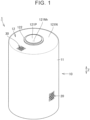
- FIG. 1 is a perspective view showing a power storage cell according to an embodiment 1 from above.
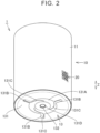
- FIG. 2 is a perspective view showing the power storage cell according to the embodiment 1 from below.
- a power storage cell 1 is a so-called cylinder-type battery.
- the power storage cell 1 includes a cell case 10, a first two-dimensional identification code 20, and a second two-dimensional identification code 30.
- the cell case 10 is configured to be capable of accommodating an electrode body.
- the cell case 10 accommodates the electrode body (not illustrated).
- the electrode body is constituted by an electrode plate group in which a positive electrode and a negative electrode are wound while a separator is interposed.
- the cell case 10 further accommodates an electrolytic solution (not illustrated).
- the cell case 10 includes an outer peripheral wall portion 11, a top surface portion 12, and a bottom surface portion 13.
- the outer peripheral wall portion 11 has a cylindrical shape as an external shape.
- the material that composes the outer peripheral wall portion 11 is not particularly limited.
- the outer peripheral wall portion 11 is formed of a conductive material such as aluminum, copper, or stainless steel.
- the top surface portion 12 closes one end of the outer peripheral wall portion 11.
- the top surface portion 12 is positioned on one side of the electrode body accommodated in the cell case 10, in an axial direction Z of the cylindrical outer peripheral wall portion 11.
- the top surface portion 12 includes a top surface body portion 121N, an external terminal 121P, and an insulating member 122.
- the top surface body portion 121N has a plate shape as an external shape.
- the top surface body portion 121N has a circular shape as an external shape, as viewed from the axial direction Z.
- a peripheral edge of the top surface body portion 121N is connected with the outer peripheral wall portion 11.
- the outer peripheral wall portion 11 and the top surface body portion 121N are integrally formed as a single member.
- the outer peripheral wall portion 11 and the top surface body portion 121N may be formed as separate members from each other. In this case, the outer peripheral wall portion 11 and the top surface body portion 121N may be joined to each other by welding such as laser welding.
- a through-hole 121Nh that passes in the axial direction Z is formed roughly at the center of the top surface body portion 121N.
- the material that composes the top surface body portion 121N is not particularly limited.
- the top surface body portion 121N is formed of aluminum, copper, stainless steel, or the like.
- the external terminal 121P has a circular shape as an external shape, as viewed from the axial direction Z.
- the external terminal 121P is positioned at an outermost end of the cell case 10 in one direction of the axial direction Z.
- the external terminal 121P is positioned on the outside of the top surface body portion 121N in the axial direction Z.
- the external terminal 121P is positioned so as to cover the through-hole 121Nh of the top surface body portion 121N.
- the through-hole 121Nh the external terminal 121P is electrically connected with one of the positive electrode and negative electrode of the electrode body accommodated in the cell case 10.
- the external terminal 121P is electrically connected with the positive electrode of the electrode body accommodated in the cell case 10.
- the external terminal 121P is a positive electrode terminal.
- the cell case 10 may further include a positive electrode current collecting plate.
- the external terminal 121P and the positive electrode of the electrode body may be electrically connected with each other, through the positive electrode current collecting plate.
- the external terminal 121P is formed of aluminum, copper, stainless steel, or the like.
- the insulating member 122 insulates the top surface body portion 121N and the external terminal 121P.
- the insulating member 122 is disposed between the top surface body portion 121N and the external terminal 121P.
- the bottom surface portion 13 closes the other end of the outer peripheral wall portion 11.
- the bottom surface portion 13 is positioned on the other side of the electrode body accommodated in the cell case 10, in the axial direction Z.
- the bottom surface portion 13 includes a bottom surface body portion 131 and a sealing plug 132.
- the bottom surface body portion 131 has a plate shape as an external shape.
- the bottom surface body portion 131 has a circular shape as an external shape, as viewed from the axial direction Z.
- a peripheral edge of the bottom surface body portion 131 is connected with the outer peripheral wall portion 11.
- the bottom surface body portion 131 is joined to a peripheral edge of the outer peripheral wall portion 11 by welding such as laser welding.
- the bottom surface body portion 131 may be fixed and connected to the outer peripheral wall portion 11 by crimping the outer peripheral wall portion 11.
- the outer peripheral wall portion 11 and the bottom surface body portion 131 may be integrally formed as a single member.
- the material that composes the bottom surface body portion 131 is not particularly limited.
- the bottom surface body portion 131 is formed of a conductive material such as aluminum, copper, or stainless steel.
- the bottom surface body portion 131 is directly joined to the positive electrode or negative electrode of the electrode body in the cell case 10, by the welding from the outside of the cell case 10. Specifically, the bottom surface body portion 131 is joined to the negative electrode. Thereby, the bottom surface body portion 131 is negatively charged. The bottom surface body portion 131 may function as a negative electrode terminal. Further, the outer peripheral wall portion 11 joined to the bottom surface body portion 131 is also negatively charged. The top surface body portion 121N formed integrally with the outer peripheral wall portion 11 is also negatively charged. Consequently, the top surface body portion 121N may be connected to another power storage cell or the like, as a negative electrode terminal.
- the bottom surface body portion 131 includes an annular convex portion 131A, a plurality of radial convex portions 131B, a plurality of welded portions 131C, and a through-hole 131D.
- the annular convex portion 131A annularly extends, as viewed from the axial direction Z.
- the annular convex portion 131A protrudes toward the inner side of the cell case 10.
- the annular convex portion 131A contacts with the negative electrode of the electrode body.
- the plurality of radial convex portions 131B extends in radial directions around the center of the bottom surface portion 13, as viewed from the axial direction Z.
- the plurality of radial convex portions 131B is arrayed separately from each other.
- the plurality of radial convex portions 131B is arrayed at regular intervals in the circumferential direction.
- the plurality of radial convex portions 131B communicates with the annular convex portion 131A.
- the plurality of radial convex portions 131B protrudes toward the inner side of the cell case 10.
- the plurality of radial convex portions 131B contacts with the negative electrode of the electrode body.
- Each of the plurality of welded portions 131C is a portion on the bottom surface body portion 131 that is joined to the negative electrode of the electrode body in the cell case 10 by welding.
- the plurality of welded portions 131C is formed by the laser welding from the outside of the cell case 10.
- the plurality of welded portions 131C is formed at the annular convex portion 131A.
- the plurality of welded portions 131C is formed so as to extend along a circumferential direction around the center of the bottom surface portion 13, as viewed from the axial direction Z.
- the plurality of welded portions 131C is formed at the plurality of radial convex portions 131B, respectively.
- the welded portions 131C are formed so as to extend along radial directions.
- the annular convex portion 131A and the plurality of radial convex portions 131B may have a thinner thickness than the other portion of the bottom surface body portion 131. Thereby, the welded portions 131C are easily formed.
- the through-hole 131D is formed at the center of the bottom surface body portion 131, as viewed from the axial direction Z.
- the through-hole 131D may be used for injecting the electrolytic solution accommodated in the cell case 10.
- the sealing plug 132 is inserted into the through-hole 131D of the bottom surface body portion 131. Thereby, the sealing plug 132 is fixed to the bottom surface body portion 131.
- the through-hole 131D and the sealing plug 132 may function as a pressure releasing valve for releasing the pressure of the interior of the cell case 10 when the pressure of the interior of the cell case 10 is excessively high.
- the first two-dimensional identification code 20 is configured such that a predetermined reader can read identification information.
- the identification information includes individual identification information about the power storage cell 1 on which the first two-dimensional identification code 20 is provided.
- the individual identification information includes the manufacture date, manufacture time, manufacture line, lot number and others of the power storage cell 1.
- the first two-dimensional identification code 20 is a QR code (R).
- the first two-dimensional identification code 20 is provided on an outer surface of the cell case 10.
- the first two-dimensional identification code 20 may be directly printed on the outer surface of the cell case 10 by ink or the like, or a label on which the first two-dimensional identification code 20 has been previously printed may be pasted to the outer surface of the cell case 10.
- the first two-dimensional identification code 20 may be impressed on the cell case 10 by laser or the like.
- the first two-dimensional identification code 20 is provided on the outer peripheral wall portion 11.
- the second two-dimensional identification code 30 is configured to enable reading of the same identification information as the first two-dimensional identification code 20. At least some of the identification information that is read from the second two-dimensional identification code 30 may be the same as the identification information that is read from the first two-dimensional identification code 20.
- the second two-dimensional identification code 30 is a QR code (R). It is preferable that the second two-dimensional identification code 30 be the same as the first two-dimensional identification code 20.
- the second two-dimensional identification code 30 is separate from the first two-dimensional identification code 20.
- the second two-dimensional identification code 30 is provided on the outer surface of the cell case 10.
- the second two-dimensional identification code 30 may be directly printed on the outer surface of the cell case 10 by ink or the like, or a label on which the second two-dimensional identification code 30 has been previously printed may be pasted to the outer surface of the cell case 10.
- the second two-dimensional identification code 30 may be impressed on the cell case 10 by laser or the like.
- the second two-dimensional identification code 30 is provided on the top surface portion 12. Specifically, the second two-dimensional identification code 30 is provided on the top surface body portion 121N.
- the position of the first two-dimensional identification code 20 and the position of the second two-dimensional identification code 30 may be mutually reversed. That is, the first two-dimensional identification code 20 may be provided on the top surface portion 12, and the second two-dimensional identification code 30 may be provided on the outer peripheral wall portion 11.
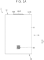
- FIG. 3A is a diagram showing the power storage cell when the first two-dimensional identification code is seen from front.
- the first two-dimensional identification code 20 is provided at a position that does not allow visually recognizing at least a part of the second two-dimensional identification code 30 when the first two-dimensional identification code 20 is seen from front.
- the first two-dimensional identification code 20 is provided at a position that does not allow visually recognizing any of the second two-dimensional identification code 30 when the first two-dimensional identification code 20 is seen from front. This is because the top surface body portion 121N extends in a plane direction orthogonal to the axial direction Z of the outer peripheral wall portion 11.
- the front of the two-dimensional identification code is at a position on a certain imaginary straight line.
- the imaginary straight line is a normal line drawn at a central portion of a region that is on the outer surface of the cell case 10 and where the two-dimensional identification code is provided.
- FIG. 3B is a diagram showing the power storage cell when the second two-dimensional identification code is seen from front.
- the second two-dimensional identification code 30 is provided at a position that does not allow visually recognizing at least a part of the first two-dimensional identification code 20 when the second two-dimensional identification code 30 is seen from front.
- the second two-dimensional identification code 30 is provided at a position that does not allow visually recognizing any of the first two-dimensional identification code 20 when the second two-dimensional identification code 30 is seen from front. This is because an outer peripheral surface of the outer peripheral wall portion 11 extends in a direction orthogonal to the plane direction in which the top surface body portion 121N extends.
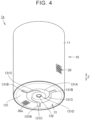
- FIG. 4 is a perspective view showing a power storage cell according to a modification of the embodiment 1 from below.
- a second two-dimensional identification code 30a is provided on the bottom surface portion 13.
- the second two-dimensional identification code 30a is provided on the bottom surface body portion 131.
- the position of the first two-dimensional identification code 20 and the position of the second two-dimensional identification code 30a may be mutually reversed. That is, the second two-dimensional identification code 30a may be provided on the outer peripheral wall portion 11, and the first two-dimensional identification code 20 may be provided on the bottom surface portion 13.
- the first two-dimensional identification code 20 is provided at a position that does not allow visually recognizing at least a part of the second two-dimensional identification code 30a when the first two-dimensional identification code 20 is seen from front.
- the second two-dimensional identification code 30a is provided at a position that does not allow visually recognizing at least a part of the first two-dimensional identification code 20 when the second two-dimensional identification code 30a is seen from front.
- the power storage cell 1 may include three or more two-dimensional identification codes.
- a third two-dimensional identification code can be disposed at positions where the first two-dimensional identification code 20 and the second two-dimensional identification code 30 can be disposed in the embodiment and the above modification.
- the power storage cell 1 includes the cell case 10, the first two-dimensional identification code 20, and the second two-dimensional identification code 30.
- the cell case 10 is configured to be capable of accommodating the electrode body.
- the first two-dimensional identification code 20 is provided on the outer surface of the cell case 10.
- the first two-dimensional identification code 20 is configured to enable the reading of the identification information.
- the second two-dimensional identification code 30 is provided on the outer surface of the cell case 10 separately from the first two-dimensional identification code 20.
- the second two-dimensional identification code 30 is configured to enable the reading of the same identification information as the first two-dimensional identification code 20.
- the second two-dimensional identification code 30 is provided at the position that does not allow visually recognizing at least a part of the first two-dimensional identification code 20 when the second two-dimensional identification code 30 is seen from front.
- the identification information can be read from the second two-dimensional identification code 30, even in a direction in which the identification information cannot be read from the first two-dimensional identification code 20. Moreover, the identification information is easily read from the two-dimensional identification code, regardless of the state of the power storage cell 1.
- the second two-dimensional identification code 30 can be exposed to the exterior of the module. Therefore, the identification information can be easily read from the two-dimensional identification code. Further, for example, when the module equipped with the power storge cell 1 is disassembled, the second two-dimensional identification code 30 can be avoided from being damaged, even when the power storage cell 1 is damaged on the front side of the first two-dimensional identification code 20. Therefore, the identification information can be easily read from the two-dimensional identification code, regardless of the state of the power storage cell 1.
- the cell case 10 includes the outer peripheral wall portion 11, the top surface portion 12, and the bottom surface portion 13.
- the outer peripheral wall portion 11 has a cylindrical shape.
- the top surface portion 12 closes one end of the outer peripheral wall portion 11.
- the bottom surface portion 13 closes the other end of the outer peripheral wall portion 11.
- One of the first two-dimensional identification code 20 and the second two-dimensional identification code 30 is provided on the outer peripheral wall portion 11.
- the other of the first two-dimensional identification code 20 and the second two-dimensional identification code 30 is provided on the top surface portion 12 or the bottom surface portion 13.
- the identification information is easily read from the two-dimensional identification code, regardless of the state of the power storage cell 1.
- the identification information can be read from the two-dimensional identification code on the outer peripheral wall portion 11.
- a plurality of power storage cells 1 is embedded in the module, and the outer peripheral wall portions 11 of the power storage cells 1 are arranged so as to face each other.
- the identification information can be read from the two-dimensional identification code on the top surface portion 12 or the bottom surface portion 13. Therefore, even when the power storage cell has a so-called cylinder-type shape, the identification information is easily read from the two-dimensional identification code, regardless of the state of the power storage cell 1.
- a power storage cell according to an embodiment 2 of the present disclosure will be described below.
- the embodiment 2 of the present disclosure is different from the embodiment 1 in the position of the first two-dimensional identification code. Descriptions about the same configurations and effects as those in the embodiment 1 are not repeated.
- FIG. 5 is a perspective view showing a power storage cell according to the embodiment 2.
- a power storage cell 1x according to the embodiment 2 of the present disclosure, one of a first two-dimensional identification code 20x and the second two-dimensional identification code 30 is provided on the top surface portion 12.
- the other of the first two-dimensional identification code 20x and the second two-dimensional identification code 30 is provided on the bottom surface portion 13.
- the identification information is easily read from the two-dimensional identification code, regardless of the state of the power storage cell 1x.
- the identification information can be read from the two-dimensional identification code provided on the other of the top surface body portion 121N of the top surface portion 12 and the bottom surface body portion 131 of the bottom surface portion 13. Therefore, even when the power storage cell has a so-called cylinder-type shape, the identification information is easily read from the two-dimensional identification code.
- the first two-dimensional identification code 20x is provided on the bottom surface portion 13 and the second two-dimensional identification code 30 is provided on the top surface portion 12.
- the position of the first two-dimensional identification code 20x and the position of the second two-dimensional identification code 30 may be mutually reversed. That is, the first two-dimensional identification code 20x may be provided on the top surface portion 12, and the second two-dimensional identification code 30 may be provided on the bottom surface portion 13.
- the first two-dimensional identification code 20x and the second two-dimensional identification code 30 are not arrayed in the axial direction Z.
- the first two-dimensional identification code 20x and the second two-dimensional identification code 30 may be arrayed in the axial direction Z.
- a power storage cell according to an embodiment 3 of the present disclosure will be described below.
- the embodiment 3 of the present disclosure is different from the embodiment 1 in the position of the second two-dimensional identification code. Descriptions about the same configurations and effects as those in the embodiment 1 are not repeated.
- FIG. 6 is a perspective view showing a power storage cell according to the embodiment 3.
- the first two-dimensional identification code 20 is provided on the outer peripheral wall portion 11.
- a second two-dimensional identification code 30y is provided on the outer peripheral wall portion 11 so as to face in a direction opposite to a direction in which the first two-dimensional identification code 20 faces.
- the identification information is easily read from the two-dimensional identification code, regardless of the state of the power storage cell 1y.
- the second two-dimensional identification code 30y which faces in the direction opposite to the direction in which the first two-dimensional identification code 20 faces, is easily avoided from being damaged. Therefore, the identification information can be easily read from the two-dimensional identification code, regardless of the state of the power storage cell 1y.
- the first two-dimensional identification code 20 and the second two-dimensional identification code 30y are not arrayed in an imaginary plane direction orthogonal to the axial direction Z.
- the first two-dimensional identification code 20 and the second two-dimensional identification code 30y may be arrayed in the imaginary plane direction orthogonal to the axial direction Z.
- configures that can be combined may be combined with each other.
Landscapes
- Engineering & Computer Science (AREA)
- Chemical & Material Sciences (AREA)
- Chemical Kinetics & Catalysis (AREA)
- Electrochemistry (AREA)
- General Chemical & Material Sciences (AREA)
- Business, Economics & Management (AREA)
- Physics & Mathematics (AREA)
- General Physics & Mathematics (AREA)
- Theoretical Computer Science (AREA)
- Manufacturing & Machinery (AREA)
- Economics (AREA)
- Human Resources & Organizations (AREA)
- General Business, Economics & Management (AREA)
- Tourism & Hospitality (AREA)
- Marketing (AREA)
- Strategic Management (AREA)
- Entrepreneurship & Innovation (AREA)
- Health & Medical Sciences (AREA)
- Operations Research (AREA)
- Quality & Reliability (AREA)
- Accounting & Taxation (AREA)
- Development Economics (AREA)
- Finance (AREA)
- Public Health (AREA)
- Water Supply & Treatment (AREA)
- General Health & Medical Sciences (AREA)
- Primary Health Care (AREA)
- Sealing Battery Cases Or Jackets (AREA)
- Electric Double-Layer Capacitors Or The Like (AREA)
Abstract
A power storage cell includes a cell case, a first two-dimensional identification code, and a second two-dimensional identification code. The cell case is configured to be capable of accommodating an electrode body. The first two-dimensional identification code is provided on an outer surface of the cell case. The first two-dimensional identification code is configured to enable reading of identification information. The second two-dimensional identification code is provided on the outer surface of the cell case separately from the first two-dimensional identification code. The second two-dimensional identification code is configured to enable reading of the same identification information as the first two-dimensional identification code. The second two-dimensional identification code is provided at a position that does not allow visually recognizing at least a part of the first two-dimensional identification code when the second two-dimensional identification code is seen from front.
Description
- The present disclosure relates to a power storge cell.
-
Japanese Unexamined Patent Application Publication No. 2011-210663 JP 2011-210663 A - In the cylindrical battery descried in
JP 2011-210663 A - For example, in a state where a power storage cell is equipped in a module, a situation where one two-dimensional code is not exposed to the exterior of the module and the other two-dimensional code also is not exposed to the exterior of the module arises easily. Further, for example, when the module equipped with the power storage cell is disassembled, a situation where one two-dimensional code is damaged and the other two-dimensional code also is damaged in the power storage cell arises easily.
- The present disclosure has been made in view of the above problem, and has an object to provide a power storage cell that makes it easy to read the identification information from the two-dimensional identification code, regardless of the state of the power storage cell.
- A power storage cell based on the present disclosure includes a cell case, a first two-dimensional identification code, and a second two-dimensional identification code. The cell case is configured to be capable of accommodating an electrode body. The first two-dimensional identification code is provided on an outer surface of the cell case. The first two-dimensional identification code is configured to enable reading of identification information. The second two-dimensional identification code is provided on the outer surface of the cell case separately from the first two-dimensional identification code. The second two-dimensional identification code is configured to enable reading of the same identification information as the first two-dimensional identification code. The second two-dimensional identification code is provided at a position that does not allow visually recognizing at least a part of the first two-dimensional identification code when the second two-dimensional identification code is seen from front.
- In the above configuration, the identification information can be read from the second two-dimensional identification code, even in a direction in which the identification information cannot be read from the first two-dimensional identification code. Moreover, the identification information is easily read from the two-dimensional identification code, regardless of the state of the power storage cell.
- For example, in a state where the power storage cell is equipped in a module, even when the first two-dimensional identification code is not exposed to the exterior of the module, the second two-dimensional identification code can be exposed to the exterior of the module. Therefore, the identification information can be easily read from the two-dimensional identification code. Further, for example, when the module equipped with the power storage cell is disassembled, the second two-dimensional identification code can be avoided from being damaged, even when the power storage cell is damaged on the front side of the first two-dimensional identification code. Therefore, the identification information can be easily read from the two-dimensional identification code, regardless of the state of the power storage cell.
- With the present disclosure, the identification information is easily read from the two-dimensional identification code, regardless of the state of the power storage cell.
- Features, advantages, and technical and industrial significance of exemplary embodiments of the invention will be described below with reference to the accompanying drawings, in which like signs denote like elements, and wherein:
-
FIG. 1 is a perspective view showing a power storge cell according to anembodiment 1 from above; -
FIG. 2 is a perspective view showing the power storage cell according to theembodiment 1 from below; -
FIG. 3A is a diagram showing the power storage cell when a first two-dimensional identification code is seen from front; -
FIG. 3B is a diagram showing the power storage cell when a second two-dimensional identification code is seen from front; -
FIG. 4 is a perspective view showing a power storage cell according to a modification of theembodiment 1 from below; -
FIG. 5 is a perspective view showing a power storage cell according to an embodiment 2; and -
FIG. 6 is a perspective view showing a power storage cell according to an embodiment 3. - Power storage cells according to embodiments of the present disclosure will be described below with reference to the drawings. In the figures, identical or corresponding portions are denoted by identical reference characters, and descriptions thereof are not repeated.
-
FIG. 1 is a perspective view showing a power storage cell according to anembodiment 1 from above.FIG. 2 is a perspective view showing the power storage cell according to theembodiment 1 from below. - As shown in
FIG. 1 andFIG. 2 , apower storage cell 1 according to theembodiment 1 of the present disclosure is a so-called cylinder-type battery. Thepower storage cell 1 includes acell case 10, a first two-dimensional identification code 20, and a second two-dimensional identification code 30. - The
cell case 10 is configured to be capable of accommodating an electrode body. In the embodiment, thecell case 10 accommodates the electrode body (not illustrated). The electrode body is constituted by an electrode plate group in which a positive electrode and a negative electrode are wound while a separator is interposed. Thecell case 10 further accommodates an electrolytic solution (not illustrated). - The
cell case 10 includes an outerperipheral wall portion 11, atop surface portion 12, and abottom surface portion 13. The outerperipheral wall portion 11 has a cylindrical shape as an external shape. The material that composes the outerperipheral wall portion 11 is not particularly limited. The outerperipheral wall portion 11 is formed of a conductive material such as aluminum, copper, or stainless steel. - The
top surface portion 12 closes one end of the outerperipheral wall portion 11. Thetop surface portion 12 is positioned on one side of the electrode body accommodated in thecell case 10, in an axial direction Z of the cylindrical outerperipheral wall portion 11. - The
top surface portion 12 includes a topsurface body portion 121N, anexternal terminal 121P, and aninsulating member 122. - The top
surface body portion 121N has a plate shape as an external shape. The topsurface body portion 121N has a circular shape as an external shape, as viewed from the axial direction Z. A peripheral edge of the topsurface body portion 121N is connected with the outerperipheral wall portion 11. In the embodiment, the outerperipheral wall portion 11 and the topsurface body portion 121N are integrally formed as a single member. The outerperipheral wall portion 11 and the topsurface body portion 121N may be formed as separate members from each other. In this case, the outerperipheral wall portion 11 and the topsurface body portion 121N may be joined to each other by welding such as laser welding. A through-hole 121Nh that passes in the axial direction Z is formed roughly at the center of the topsurface body portion 121N. The material that composes the topsurface body portion 121N is not particularly limited. The topsurface body portion 121N is formed of aluminum, copper, stainless steel, or the like. - The
external terminal 121P has a circular shape as an external shape, as viewed from the axial direction Z. Theexternal terminal 121P is positioned at an outermost end of thecell case 10 in one direction of the axial direction Z. Theexternal terminal 121P is positioned on the outside of the topsurface body portion 121N in the axial direction Z. Theexternal terminal 121P is positioned so as to cover the through-hole 121Nh of the topsurface body portion 121N. Through the through-hole 121Nh, theexternal terminal 121P is electrically connected with one of the positive electrode and negative electrode of the electrode body accommodated in thecell case 10. Specifically, through the through-hole 121Nh, theexternal terminal 121P is electrically connected with the positive electrode of the electrode body accommodated in thecell case 10. Theexternal terminal 121P is a positive electrode terminal. In this case, thecell case 10 may further include a positive electrode current collecting plate. Theexternal terminal 121P and the positive electrode of the electrode body may be electrically connected with each other, through the positive electrode current collecting plate. Theexternal terminal 121P is formed of aluminum, copper, stainless steel, or the like. - The insulating
member 122 insulates the topsurface body portion 121N and theexternal terminal 121P. The insulatingmember 122 is disposed between the topsurface body portion 121N and theexternal terminal 121P. - The
bottom surface portion 13 closes the other end of the outerperipheral wall portion 11. Thebottom surface portion 13 is positioned on the other side of the electrode body accommodated in thecell case 10, in the axial direction Z. - The
bottom surface portion 13 includes a bottomsurface body portion 131 and a sealingplug 132. The bottomsurface body portion 131 has a plate shape as an external shape. The bottomsurface body portion 131 has a circular shape as an external shape, as viewed from the axial direction Z. A peripheral edge of the bottomsurface body portion 131 is connected with the outerperipheral wall portion 11. The bottomsurface body portion 131 is joined to a peripheral edge of the outerperipheral wall portion 11 by welding such as laser welding. The bottomsurface body portion 131 may be fixed and connected to the outerperipheral wall portion 11 by crimping the outerperipheral wall portion 11. In the case where the topsurface body portion 121N and the outerperipheral wall portion 11 are formed as different members from each other, the outerperipheral wall portion 11 and the bottomsurface body portion 131 may be integrally formed as a single member. The material that composes the bottomsurface body portion 131 is not particularly limited. The bottomsurface body portion 131 is formed of a conductive material such as aluminum, copper, or stainless steel. - The bottom
surface body portion 131 is directly joined to the positive electrode or negative electrode of the electrode body in thecell case 10, by the welding from the outside of thecell case 10. Specifically, the bottomsurface body portion 131 is joined to the negative electrode. Thereby, the bottomsurface body portion 131 is negatively charged. The bottomsurface body portion 131 may function as a negative electrode terminal. Further, the outerperipheral wall portion 11 joined to the bottomsurface body portion 131 is also negatively charged. The topsurface body portion 121N formed integrally with the outerperipheral wall portion 11 is also negatively charged. Consequently, the topsurface body portion 121N may be connected to another power storage cell or the like, as a negative electrode terminal. - The bottom
surface body portion 131 includes an annularconvex portion 131A, a plurality of radialconvex portions 131B, a plurality of weldedportions 131C, and a through-hole 131D. The annularconvex portion 131A annularly extends, as viewed from the axial direction Z. The annularconvex portion 131A protrudes toward the inner side of thecell case 10. The annularconvex portion 131A contacts with the negative electrode of the electrode body. - The plurality of radial
convex portions 131B extends in radial directions around the center of thebottom surface portion 13, as viewed from the axial direction Z. The plurality of radialconvex portions 131B is arrayed separately from each other. The plurality of radialconvex portions 131B is arrayed at regular intervals in the circumferential direction. The plurality of radialconvex portions 131B communicates with the annularconvex portion 131A. The plurality of radialconvex portions 131B protrudes toward the inner side of thecell case 10. The plurality of radialconvex portions 131B contacts with the negative electrode of the electrode body. - Each of the plurality of welded
portions 131C is a portion on the bottomsurface body portion 131 that is joined to the negative electrode of the electrode body in thecell case 10 by welding. The plurality of weldedportions 131C is formed by the laser welding from the outside of thecell case 10. The plurality of weldedportions 131C is formed at the annularconvex portion 131A. At the annularconvex portion 131A, the plurality of weldedportions 131C is formed so as to extend along a circumferential direction around the center of thebottom surface portion 13, as viewed from the axial direction Z. The plurality of weldedportions 131C is formed at the plurality of radialconvex portions 131B, respectively. At the radialconvex portions 131B, the weldedportions 131C are formed so as to extend along radial directions. The annularconvex portion 131A and the plurality of radialconvex portions 131B may have a thinner thickness than the other portion of the bottomsurface body portion 131. Thereby, the weldedportions 131C are easily formed. - The through-
hole 131D is formed at the center of the bottomsurface body portion 131, as viewed from the axial direction Z. The through-hole 131D may be used for injecting the electrolytic solution accommodated in thecell case 10. - The sealing
plug 132 is inserted into the through-hole 131D of the bottomsurface body portion 131. Thereby, the sealingplug 132 is fixed to the bottomsurface body portion 131. The through-hole 131D and the sealingplug 132 may function as a pressure releasing valve for releasing the pressure of the interior of thecell case 10 when the pressure of the interior of thecell case 10 is excessively high. - The first two-
dimensional identification code 20 is configured such that a predetermined reader can read identification information. For example, the identification information includes individual identification information about thepower storage cell 1 on which the first two-dimensional identification code 20 is provided. For example, the individual identification information includes the manufacture date, manufacture time, manufacture line, lot number and others of thepower storage cell 1. For example, the first two-dimensional identification code 20 is a QR code (R). - The first two-
dimensional identification code 20 is provided on an outer surface of thecell case 10. The first two-dimensional identification code 20 may be directly printed on the outer surface of thecell case 10 by ink or the like, or a label on which the first two-dimensional identification code 20 has been previously printed may be pasted to the outer surface of thecell case 10. The first two-dimensional identification code 20 may be impressed on thecell case 10 by laser or the like. In the embodiment, the first two-dimensional identification code 20 is provided on the outerperipheral wall portion 11. - The second two-
dimensional identification code 30 is configured to enable reading of the same identification information as the first two-dimensional identification code 20. At least some of the identification information that is read from the second two-dimensional identification code 30 may be the same as the identification information that is read from the first two-dimensional identification code 20. For example, the second two-dimensional identification code 30 is a QR code (R). It is preferable that the second two-dimensional identification code 30 be the same as the first two-dimensional identification code 20. - The second two-
dimensional identification code 30 is separate from the first two-dimensional identification code 20. The second two-dimensional identification code 30 is provided on the outer surface of thecell case 10. The second two-dimensional identification code 30 may be directly printed on the outer surface of thecell case 10 by ink or the like, or a label on which the second two-dimensional identification code 30 has been previously printed may be pasted to the outer surface of thecell case 10. The second two-dimensional identification code 30 may be impressed on thecell case 10 by laser or the like. - In the embodiment, the second two-
dimensional identification code 30 is provided on thetop surface portion 12. Specifically, the second two-dimensional identification code 30 is provided on the topsurface body portion 121N. - The position of the first two-
dimensional identification code 20 and the position of the second two-dimensional identification code 30 may be mutually reversed. That is, the first two-dimensional identification code 20 may be provided on thetop surface portion 12, and the second two-dimensional identification code 30 may be provided on the outerperipheral wall portion 11. -
FIG. 3A is a diagram showing the power storage cell when the first two-dimensional identification code is seen from front. As shown inFIG. 3A , the first two-dimensional identification code 20 is provided at a position that does not allow visually recognizing at least a part of the second two-dimensional identification code 30 when the first two-dimensional identification code 20 is seen from front. Specifically, the first two-dimensional identification code 20 is provided at a position that does not allow visually recognizing any of the second two-dimensional identification code 30 when the first two-dimensional identification code 20 is seen from front. This is because the topsurface body portion 121N extends in a plane direction orthogonal to the axial direction Z of the outerperipheral wall portion 11. - In the present specification, the front of the two-dimensional identification code is at a position on a certain imaginary straight line. The imaginary straight line is a normal line drawn at a central portion of a region that is on the outer surface of the
cell case 10 and where the two-dimensional identification code is provided. -
FIG. 3B is a diagram showing the power storage cell when the second two-dimensional identification code is seen from front. As shown inFIG. 3B , the second two-dimensional identification code 30 is provided at a position that does not allow visually recognizing at least a part of the first two-dimensional identification code 20 when the second two-dimensional identification code 30 is seen from front. Specifically, the second two-dimensional identification code 30 is provided at a position that does not allow visually recognizing any of the first two-dimensional identification code 20 when the second two-dimensional identification code 30 is seen from front. This is because an outer peripheral surface of the outerperipheral wall portion 11 extends in a direction orthogonal to the plane direction in which the topsurface body portion 121N extends. - Further, the second two-
dimensional identification code 30 may be provided on thebottom surface portion 13.FIG. 4 is a perspective view showing a power storage cell according to a modification of theembodiment 1 from below. As shown inFIG. 4 , in apower storage cell 1a according to the modification of theembodiment 1, a second two-dimensional identification code 30a is provided on thebottom surface portion 13. Specifically, the second two-dimensional identification code 30a is provided on the bottomsurface body portion 131. Also in the modification, the position of the first two-dimensional identification code 20 and the position of the second two-dimensional identification code 30a may be mutually reversed. That is, the second two-dimensional identification code 30a may be provided on the outerperipheral wall portion 11, and the first two-dimensional identification code 20 may be provided on thebottom surface portion 13. - Also in the embodiment, the first two-
dimensional identification code 20 is provided at a position that does not allow visually recognizing at least a part of the second two-dimensional identification code 30a when the first two-dimensional identification code 20 is seen from front. The second two-dimensional identification code 30a is provided at a position that does not allow visually recognizing at least a part of the first two-dimensional identification code 20 when the second two-dimensional identification code 30a is seen from front. - Further, the
power storage cell 1 may include three or more two-dimensional identification codes. For example, a third two-dimensional identification code can be disposed at positions where the first two-dimensional identification code 20 and the second two-dimensional identification code 30 can be disposed in the embodiment and the above modification. - As described above, the
power storage cell 1 according to theembodiment 1 of the present disclosure includes thecell case 10, the first two-dimensional identification code 20, and the second two-dimensional identification code 30. Thecell case 10 is configured to be capable of accommodating the electrode body. The first two-dimensional identification code 20 is provided on the outer surface of thecell case 10. The first two-dimensional identification code 20 is configured to enable the reading of the identification information. The second two-dimensional identification code 30 is provided on the outer surface of thecell case 10 separately from the first two-dimensional identification code 20. The second two-dimensional identification code 30 is configured to enable the reading of the same identification information as the first two-dimensional identification code 20. The second two-dimensional identification code 30 is provided at the position that does not allow visually recognizing at least a part of the first two-dimensional identification code 20 when the second two-dimensional identification code 30 is seen from front. - In the above configuration, the identification information can be read from the second two-
dimensional identification code 30, even in a direction in which the identification information cannot be read from the first two-dimensional identification code 20. Moreover, the identification information is easily read from the two-dimensional identification code, regardless of the state of thepower storage cell 1. - For example, in a state where the
power storage cell 1 is equipped in a module, even when the first two-dimensional identification code 20 is not exposed to the exterior of the module, the second two-dimensional identification code 30 can be exposed to the exterior of the module. Therefore, the identification information can be easily read from the two-dimensional identification code. Further, for example, when the module equipped with thepower storge cell 1 is disassembled, the second two-dimensional identification code 30 can be avoided from being damaged, even when thepower storage cell 1 is damaged on the front side of the first two-dimensional identification code 20. Therefore, the identification information can be easily read from the two-dimensional identification code, regardless of the state of thepower storage cell 1. - Furthermore, in the
embodiment 1 of the present disclosure, thecell case 10 includes the outerperipheral wall portion 11, thetop surface portion 12, and thebottom surface portion 13. The outerperipheral wall portion 11 has a cylindrical shape. Thetop surface portion 12 closes one end of the outerperipheral wall portion 11. Thebottom surface portion 13 closes the other end of the outerperipheral wall portion 11. One of the first two-dimensional identification code 20 and the second two-dimensional identification code 30 is provided on the outerperipheral wall portion 11. The other of the first two-dimensional identification code 20 and the second two-dimensional identification code 30 is provided on thetop surface portion 12 or thebottom surface portion 13. - In the above configuration, even when the
power storage cell 1 has a so-called cylinder-type shape, the identification information is easily read from the two-dimensional identification code, regardless of the state of thepower storage cell 1. - For example, in a state before the
power storage cell 1 is embedded in the module, the identification information can be read from the two-dimensional identification code on the outerperipheral wall portion 11. Meanwhile, in some cases, a plurality ofpower storage cells 1 is embedded in the module, and the outerperipheral wall portions 11 of thepower storage cells 1 are arranged so as to face each other. In this case, the identification information can be read from the two-dimensional identification code on thetop surface portion 12 or thebottom surface portion 13. Therefore, even when the power storage cell has a so-called cylinder-type shape, the identification information is easily read from the two-dimensional identification code, regardless of the state of thepower storage cell 1. - A power storage cell according to an embodiment 2 of the present disclosure will be described below. The embodiment 2 of the present disclosure is different from the
embodiment 1 in the position of the first two-dimensional identification code. Descriptions about the same configurations and effects as those in theembodiment 1 are not repeated. -
FIG. 5 is a perspective view showing a power storage cell according to the embodiment 2. As shown inFIG. 5 , in apower storage cell 1x according to the embodiment 2 of the present disclosure, one of a first two-dimensional identification code 20x and the second two-dimensional identification code 30 is provided on thetop surface portion 12. The other of the first two-dimensional identification code 20x and the second two-dimensional identification code 30 is provided on thebottom surface portion 13. - In the above configuration, even when the
power storage cell 1x has a so-called cylinder-type shape, the identification information is easily read from the two-dimensional identification code, regardless of the state of thepower storage cell 1x. - For example, in the case where one of the top
surface body portion 121N of thetop surface portion 12 and the bottomsurface body portion 131 of thebottom surface portion 13 is connected to a bus-bar or the like as the negative electrode terminal, the identification information can be read from the two-dimensional identification code provided on the other of the topsurface body portion 121N of thetop surface portion 12 and the bottomsurface body portion 131 of thebottom surface portion 13. Therefore, even when the power storage cell has a so-called cylinder-type shape, the identification information is easily read from the two-dimensional identification code. - In the embodiment, specifically, the first two-
dimensional identification code 20x is provided on thebottom surface portion 13, and the second two-dimensional identification code 30 is provided on thetop surface portion 12. The position of the first two-dimensional identification code 20x and the position of the second two-dimensional identification code 30 may be mutually reversed. That is, the first two-dimensional identification code 20x may be provided on thetop surface portion 12, and the second two-dimensional identification code 30 may be provided on thebottom surface portion 13. - The first two-
dimensional identification code 20x and the second two-dimensional identification code 30 are not arrayed in the axial direction Z. The first two-dimensional identification code 20x and the second two-dimensional identification code 30 may be arrayed in the axial direction Z. - A power storage cell according to an embodiment 3 of the present disclosure will be described below. The embodiment 3 of the present disclosure is different from the
embodiment 1 in the position of the second two-dimensional identification code. Descriptions about the same configurations and effects as those in theembodiment 1 are not repeated. -
FIG. 6 is a perspective view showing a power storage cell according to the embodiment 3. As shown inFIG. 6 , in apower storage cell 1y according to the embodiment 3 of the present disclosure, the first two-dimensional identification code 20 is provided on the outerperipheral wall portion 11. A second two-dimensional identification code 30y is provided on the outerperipheral wall portion 11 so as to face in a direction opposite to a direction in which the first two-dimensional identification code 20 faces. - In the above configuration, even when the
power storage cell 1y has a so-called cylinder-type shape, the identification information is easily read from the two-dimensional identification code, regardless of the state of thepower storage cell 1y. - For example, even when the
power storage cell 1y is damaged on the front side of the first two-dimensional identification code 20, the second two-dimensional identification code 30y, which faces in the direction opposite to the direction in which the first two-dimensional identification code 20 faces, is easily avoided from being damaged. Therefore, the identification information can be easily read from the two-dimensional identification code, regardless of the state of thepower storage cell 1y. - In the embodiment, the first two-
dimensional identification code 20 and the second two-dimensional identification code 30y are not arrayed in an imaginary plane direction orthogonal to the axial direction Z. The first two-dimensional identification code 20 and the second two-dimensional identification code 30y may be arrayed in the imaginary plane direction orthogonal to the axial direction Z. - In the above description of the embodiments, configures that can be combined may be combined with each other.
- It should be understood that the above disclosed embodiments are examples and are not limitative in all respects. It is intended that the scope of the present disclosure is shown not by the above description of the embodiments but by the claims and includes all alterations within meanings and scopes that are equivalent to the claims.
Claims (4)
- A power storage cell comprising:a cell case configured to be capable of accommodating an electrode body;a first two-dimensional identification code provided on an outer surface of the cell case and configured to enable reading of identification information; anda second two-dimensional identification code provided on the outer surface of the cell case separately from the first two-dimensional identification code and configured to enable reading of the same identification information as the first two-dimensional identification code, wherein the second two-dimensional identification code is provided at a position that does not allow visually recognizing at least a part of the first two-dimensional identification code when the second two-dimensional identification code is seen from front.
- The power storage cell according to claim 1, wherein:the cell case includesa cylindrical outer peripheral wall portion,a top surface portion that closes one end of the outer peripheral wall portion, anda bottom surface portion that closes another end of the outer peripheral wall portion;one of the first two-dimensional identification code and the second two-dimensional identification code is provided on the outer peripheral wall portion; andanother of the first two-dimensional identification code and the second two-dimensional identification code is provided on the top surface portion or the bottom surface portion.
- The power storage cell according to claim 1, wherein:the cell case includesa cylindrical outer peripheral wall portion,a top surface portion that closes one end of the outer peripheral wall portion, anda bottom surface portion that closes another end of the outer peripheral wall portion;one of the first two-dimensional identification code and the second two-dimensional identification code is provided on the top surface portion; andanother of the first two-dimensional identification code and the second two-dimensional identification code is provided on the bottom surface portion.
- The power storage cell according to claim 1, wherein:the cell case includesa cylindrical outer peripheral wall portion,a top surface portion that closes one end of the outer peripheral wall portion, anda bottom surface portion that closes another end of the outer peripheral wall portion;the first two-dimensional identification code is provided on the outer peripheral wall portion; andthe second two-dimensional identification code is provided on the outer peripheral wall portion so as to face in a direction opposite to a direction in which the first two-dimensional identification code faces.
Applications Claiming Priority (1)
| Application Number | Priority Date | Filing Date | Title |
|---|---|---|---|
| JP2023148306A JP2025041174A (en) | 2023-09-13 | 2023-09-13 | Energy storage cell |
Publications (1)
| Publication Number | Publication Date |
|---|---|
| EP4524814A1 true EP4524814A1 (en) | 2025-03-19 |
Family
ID=92746488
Family Applications (1)
| Application Number | Title | Priority Date | Filing Date |
|---|---|---|---|
| EP24199569.5A Pending EP4524814A1 (en) | 2023-09-13 | 2024-09-10 | Power storage cell |
Country Status (5)
| Country | Link |
|---|---|
| US (1) | US20250087761A1 (en) |
| EP (1) | EP4524814A1 (en) |
| JP (1) | JP2025041174A (en) |
| KR (1) | KR20250039296A (en) |
| CN (2) | CN223181236U (en) |
Citations (6)
| Publication number | Priority date | Publication date | Assignee | Title |
|---|---|---|---|---|
| EP0581301A2 (en) * | 1992-07-30 | 1994-02-02 | Werner Dr. Baumann | Individualising and machine readable identifikation means for products, containers for the product and their packaging |
| JP2011210663A (en) | 2010-03-30 | 2011-10-20 | Panasonic Corp | Cylindrical battery with individual identification information |
| US20190049520A1 (en) * | 2016-09-30 | 2019-02-14 | Faraday&Future Inc. | Battery cell full life tracking system |
| KR102139620B1 (en) * | 2020-05-13 | 2020-07-31 | 주식회사 위챌린지 | Method And Apparatus for Managing Logistics by Using Quick Response Code |
| DE102021106817A1 (en) * | 2020-06-18 | 2021-12-23 | Fischerwerke Gmbh & Co. Kg | Screw element |
| WO2023106831A1 (en) * | 2021-12-07 | 2023-06-15 | 주식회사 엘지에너지솔루션 | Barcode scanning device of cylindrical secondary battery |
Family Cites Families (1)
| Publication number | Priority date | Publication date | Assignee | Title |
|---|---|---|---|---|
| JP2004327281A (en) * | 2003-04-25 | 2004-11-18 | Sii Micro Parts Ltd | Electrochemical cell |
-
2023
- 2023-09-13 JP JP2023148306A patent/JP2025041174A/en active Pending
-
2024
- 2024-06-26 US US18/754,611 patent/US20250087761A1/en active Pending
- 2024-09-10 EP EP24199569.5A patent/EP4524814A1/en active Pending
- 2024-09-11 KR KR1020240123649A patent/KR20250039296A/en active Pending
- 2024-09-11 CN CN202422221812.0U patent/CN223181236U/en active Active
- 2024-09-11 CN CN202411268868.XA patent/CN119627320A/en active Pending
Patent Citations (7)
| Publication number | Priority date | Publication date | Assignee | Title |
|---|---|---|---|---|
| EP0581301A2 (en) * | 1992-07-30 | 1994-02-02 | Werner Dr. Baumann | Individualising and machine readable identifikation means for products, containers for the product and their packaging |
| JP2011210663A (en) | 2010-03-30 | 2011-10-20 | Panasonic Corp | Cylindrical battery with individual identification information |
| US20190049520A1 (en) * | 2016-09-30 | 2019-02-14 | Faraday&Future Inc. | Battery cell full life tracking system |
| KR102139620B1 (en) * | 2020-05-13 | 2020-07-31 | 주식회사 위챌린지 | Method And Apparatus for Managing Logistics by Using Quick Response Code |
| DE102021106817A1 (en) * | 2020-06-18 | 2021-12-23 | Fischerwerke Gmbh & Co. Kg | Screw element |
| WO2023106831A1 (en) * | 2021-12-07 | 2023-06-15 | 주식회사 엘지에너지솔루션 | Barcode scanning device of cylindrical secondary battery |
| EP4446936A1 (en) * | 2021-12-07 | 2024-10-16 | LG Energy Solution, Ltd. | Barcode scanning device of cylindrical secondary battery |
Also Published As
| Publication number | Publication date |
|---|---|
| CN119627320A (en) | 2025-03-14 |
| KR20250039296A (en) | 2025-03-20 |
| CN223181236U (en) | 2025-08-01 |
| JP2025041174A (en) | 2025-03-26 |
| US20250087761A1 (en) | 2025-03-13 |
Similar Documents
| Publication | Publication Date | Title |
|---|---|---|
| KR20220131318A (en) | Cylindrical battery cell, battery, power consumption device, manufacturing method and manufacturing system | |
| US11024892B2 (en) | Dual sided reusable battery indicator | |
| US9660227B2 (en) | Sealing plate for prismatic secondary battery and prismatic secondary battery using the sealing plate | |
| KR102647962B1 (en) | Secondary battery and method for manufacturing the battery | |
| US9793572B2 (en) | Rechargeable battery | |
| US8991232B2 (en) | Sealing plate for prismatic secondary battery, method for producing the same, and prismatic secondary battery using the same | |
| EP3535799B1 (en) | Single sided reusable battery indicator | |
| EP3734708B1 (en) | Cell module | |
| US10490801B2 (en) | Battery pack protection element attachment tab, battery pack parallel fixing component, and battery pack | |
| WO2024099177A1 (en) | End cap assembly, energy storage apparatus, and electric device | |
| EP4293767A1 (en) | Battery connecting member, battery and battery manufacturing method | |
| US9059460B2 (en) | Prismatic secondary battery | |
| EP4524814A1 (en) | Power storage cell | |
| EP3367463A2 (en) | Battery module, and battery pack and vehicle comprising same | |
| US20190036087A1 (en) | Rectangular secondary battery and assembled battery using the rectangular secondary battery | |
| US12040462B2 (en) | Power storage module and power storage cell | |
| KR20240070994A (en) | Battery having a plurality of beading portions | |
| US20250293327A1 (en) | Power storage device | |
| EP4611147A1 (en) | Case component, battery cell, battery, and electrical device | |
| CN223260796U (en) | Battery cells, battery devices and power-consuming devices | |
| EP4475292A1 (en) | End cover assembly of battery cell, battery cell, battery, and electric device | |
| CN219180640U (en) | Battery end caps, single cells, battery packs and electrical equipment | |
| CN121460804A (en) | Secondary battery and secondary battery case | |
| CN119833903A (en) | Battery module |
Legal Events
| Date | Code | Title | Description |
|---|---|---|---|
| PUAI | Public reference made under article 153(3) epc to a published international application that has entered the european phase |
Free format text: ORIGINAL CODE: 0009012 |
|
| STAA | Information on the status of an ep patent application or granted ep patent |
Free format text: STATUS: REQUEST FOR EXAMINATION WAS MADE |
|
| 17P | Request for examination filed |
Effective date: 20240922 |
|
| AK | Designated contracting states |
Kind code of ref document: A1 Designated state(s): AL AT BE BG CH CY CZ DE DK EE ES FI FR GB GR HR HU IE IS IT LI LT LU LV MC ME MK MT NL NO PL PT RO RS SE SI SK SM TR |
|
| STAA | Information on the status of an ep patent application or granted ep patent |
Free format text: STATUS: EXAMINATION IS IN PROGRESS |
|
| 17Q | First examination report despatched |
Effective date: 20260107 |