EP4524722A1 - Systembauvorrichtung - Google Patents
Systembauvorrichtung Download PDFInfo
- Publication number
- EP4524722A1 EP4524722A1 EP23803357.5A EP23803357A EP4524722A1 EP 4524722 A1 EP4524722 A1 EP 4524722A1 EP 23803357 A EP23803357 A EP 23803357A EP 4524722 A1 EP4524722 A1 EP 4524722A1
- Authority
- EP
- European Patent Office
- Prior art keywords
- source code
- setting change
- section
- infrastructure resource
- basis
- Prior art date
- Legal status (The legal status is an assumption and is not a legal conclusion. Google has not performed a legal analysis and makes no representation as to the accuracy of the status listed.)
- Pending
Links
Images


Classifications
-
- G—PHYSICS
- G06—COMPUTING OR CALCULATING; COUNTING
- G06F—ELECTRIC DIGITAL DATA PROCESSING
- G06F8/00—Arrangements for software engineering
- G06F8/60—Software deployment
-
- G—PHYSICS
- G06—COMPUTING OR CALCULATING; COUNTING
- G06F—ELECTRIC DIGITAL DATA PROCESSING
- G06F8/00—Arrangements for software engineering
- G06F8/30—Creation or generation of source code
- G06F8/35—Creation or generation of source code model driven
-
- G—PHYSICS
- G06—COMPUTING OR CALCULATING; COUNTING
- G06F—ELECTRIC DIGITAL DATA PROCESSING
- G06F8/00—Arrangements for software engineering
- G06F8/70—Software maintenance or management
- G06F8/71—Version control; Configuration management
-
- G—PHYSICS
- G06—COMPUTING OR CALCULATING; COUNTING
- G06F—ELECTRIC DIGITAL DATA PROCESSING
- G06F9/00—Arrangements for program control, e.g. control units
- G06F9/06—Arrangements for program control, e.g. control units using stored programs, i.e. using an internal store of processing equipment to receive or retain programs
- G06F9/44—Arrangements for executing specific programs
- G06F9/445—Program loading or initiating
- G06F9/44505—Configuring for program initiating, e.g. using registry, configuration files
-
- G—PHYSICS
- G06—COMPUTING OR CALCULATING; COUNTING
- G06F—ELECTRIC DIGITAL DATA PROCESSING
- G06F8/00—Arrangements for software engineering
- G06F8/30—Creation or generation of source code
-
- G—PHYSICS
- G06—COMPUTING OR CALCULATING; COUNTING
- G06F—ELECTRIC DIGITAL DATA PROCESSING
- G06F9/00—Arrangements for program control, e.g. control units
- G06F9/06—Arrangements for program control, e.g. control units using stored programs, i.e. using an internal store of processing equipment to receive or retain programs
- G06F9/44—Arrangements for executing specific programs
- G06F9/455—Emulation; Interpretation; Software simulation, e.g. virtualisation or emulation of application or operating system execution engines
- G06F9/45533—Hypervisors; Virtual machine monitors
Definitions
- the present invention relates to a system constructing device that constructs a system in a predetermined execution environment.
- Patent Literature 1 According to a technology of Patent Literature 1, the technology is disclosed which converts an order sheet describing a system requirement into a source code on the basis of the order sheet, and automates the deployment of resources.
- Patent Literature 1 enables automatic construction of a system according to the system requirement even in a case where a user does not have coding knowledge. Meanwhile, there is a problem in that, when the user changes the configuration of the deployed system without changing the source code, the source code of the target system and the configuration of the target system differ from each other.
- Patent Literature 2 describes a technology that detects the presence or absence of a setting change in the system, and reflects the detected setting change in the source code.
- Patent Literature 2 presents a problem in that apparatuses included in a construction target system are set as a monitoring target, and a change such as the addition of a new apparatus to the system cannot be reflected in the source code.
- a coding rule as a manner of writing the source code is often different depending on the user.
- the coding rule of the corrected source code may lack consistency.
- it is necessary to make a correction such that the source code has consistency after the reflection with an objective of facilitating the management of the source code and the understanding of the user.
- the present invention has been made in view of the problems as described above. It is an object of the present invention to correct a difference between the source code and the configuration of a system in a manner adjusted to a writing method of the user, including the addition of a new resource to the system, when a user changes the configuration of the system without changing the source code.
- a system constructing device is a system constructing device for constructing a system including an infrastructure resource and a setting value of the relevant infrastructure resource in a predetermined execution environment, the system constructing device including: an input section that inputs a request for a system construction satisfying a desired requirement; a system source code generating section that generates first source code defining a system satisfying the desired requirement; a deploying section that deploys and constructs the system in the execution environment on the basis of the request; a setting change detecting section that, when the system constructed in the execution environment is changed, detects a difference between second source code defining the relevant changed system and the first source code; and a setting change reflecting section that reflects the difference detected by the setting change detecting section in the first source code, the setting change reflecting section reflecting the difference in the first source code on the basis of a coding rule applied to the first source code.
- the system constructing device in accordance with the present invention when the user changes the configuration of the system without changing the construction information of the system, the difference between the construction information of the original system and the configuration of the changed system can be corrected in a manner in which the coding rule is unified.
- FIG. 1 illustrates an example of a hardware configuration of a system constructing device 100 according to the present embodiment.
- the system constructing device 100 includes hardware such as an arithmetic device 110, a storage device 120, an input-output I/F (Interface) 130, and a communication I/F (Interface) 140.
- hardware such as an arithmetic device 110, a storage device 120, an input-output I/F (Interface) 130, and a communication I/F (Interface) 140.
- the arithmetic device 110 is a CPU (Central Processing Unit), for example.
- the arithmetic device 110 exerts various functions to be described later by the processing of the CPU.
- the storage device 120 includes a RAM (Random Access Memory) and a ROM (Read Only Memory), for example.
- the storage device 120 stores data used by the arithmetic device 110.
- the input-output I/F 130 is, for example, a display having a touch panel function.
- the input-output I/F 130 displays, on a screen, a result of processing by the arithmetic device 110 and the user interface of a portal screen 210 to be described later.
- the communication I/F 140 is, for example, a communication chip or a NIC (Network Interface Card).
- the communication I/F 140 is used for communication with an execution environment 280 and a user 201 to be described later.
- the data may be received via the input-output I/F 130, and the data may be received via the communication I/F 140.
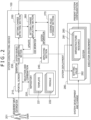
- FIG. 2 is a functional block diagram illustrating an example of a configuration of functional sections possessed by the system constructing device 100.
- the system constructing device 100 includes the portal screen 210, a repository 220, a system source code generating section 230, a deploying section 240, a setting change detecting section 250, a setting change reflecting section 260, and a coding rule storage section 270.
- the source code of templates 221 and modules 222 for deployment is registered in the designated repository 220 in advance.
- An example of the repository 220 is GitHub (https://github.com/) in a case of cloud service or GitLab in a case of OSS.
- An example of the source code will be described later with reference to FIG. 6 .
- FIG. 2 illustrates an example in which a plurality of templates 221 and modules 222 are managed in one repository 220
- a configuration may be adopted in which the repository 220 is divided for respective source codes corresponding to a plurality of projects, respectively.
- the source code is utilized to construct a specific system 281.
- a specific system 281 For example, not only a configuration in which one system 281 corresponds to one template 221 but also a module 222 as a set of functions constituting a part of the system 281 is included in the source code.
- the system source code of one system 281 is generated by combining a plurality of modules 222 with each other.
- various kinds of information for management and display on the present device 100 include the template 221 and the modules 222 as the source code for constructing the system 281, an entity or a reference of the system source code, and the like.
- the system constructing device 100 displays the portal screen 210 on a display device not illustrated for the user 201 of the system constructing device 100.
- An example of the portal screen 210 will be described later with reference to FIG. 4 and FIG. 5 .
- the portal screen 210 is mounted with a CPU not illustrated, and presents system candidates from the templates 221 and the modules 222 within the repository 220 according to a selection of a user, as will be described later.
- the user 201 selects a system 281 desired to be constructed this time by using the portal screen 210. For example, the user 201 inputs a functional requirement and a non-functional requirement of cloud service, and a template 221 prepared in advance is presented.
- the template 221 is a service obtained by combining a public cloud service, a private cloud service, and the like satisfying each requirement on the basis of actual results in the past.
- the non-functional requirement may include a requirement related to a network.
- Examples of the requirement related to the network include the presence or absence of usage of a public IP, the presence or absence of usage of a firewall, the presence or absence of usage of an encrypting function, and the like.
- the requirement related to the network is not limited to these, but may include various requirements related to the network.
- the functional requirement may include information indicating which of a plurality of kinds of clouds the execution environment 280 used is.
- the functional requirement may include various requirements related to a purpose of the system 281 and an infrastructure in addition to the above-described requirement.
- customization is performed by changing each infrastructure resource 283 of the presented template 221 to another infrastructure resource 283 capable of implementing similar functions, or adding or deleting an infrastructure resource 283. Then, after the customization, a system 281 desired to be constructed is selected by inputting, from a parameter sheet or the like, a setting value 282 needed by each infrastructure resource 283 for deployment.
- the system source code generating section 230 When the user 201 selects the system 281 desired to be constructed, the system source code generating section 230 generates system source code by using the template 221 and the modules 222 of the selected system 281 from the repository 220.
- the execution environment 280 is an environment for operating the system 281.
- the execution environment 280 is, for example, a public cloud service, a private cloud service, a cluster of IT resources managed by an orchestration tool such as OpenStack or Kubernetes, or the like.
- the execution environment 280 in which the system 281 selected by the user 201 is operated may be in a form specified by the user 201.
- the execution environment 280 may be an execution environment different for each user 201, or may be in a form in which the one execution environment is shared.
- the system 281 including the infrastructure resource 283, the setting value 282 of the infrastructure resource 283, and the like is constructed in the execution environment 280 on the basis of the system source code.
- the infrastructure resource 283 may be one or a plurality of infrastructure resources according to the description of the system source code.
- the user 201 makes a necessary change to the constructed system 281 in the execution environment 280, and thereby performs development (change made to the system 281) suited to a purpose of the user 201.
- the setting change detecting section 250 detects the presence or absence of a setting change in the system 281 as a construction target. When there is a setting change in the system 281, the setting change detecting section 250 detects and extracts setting change content as a difference between the configuration of the system 281 defined by the system source code generated by the system source code generating section 230 and the present system 281 in the execution environment.
- the setting change reflecting section 260 reflects the difference detected by the setting change detecting section 250 in the system source code generated by the system source code generating section 230, on the basis of a coding rule stored in the coding rule storage section 270.
- the coding rule includes, for example, a rule that, as a definition of a variable name, the variable name be derived from a standard variable name presented by each vendor, a rule that a variable of an ID or the like not be hard coded, and the like.
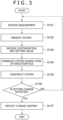
- FIG. 3 is a flowchart illustrating an example of processing performed by the system constructing device 100 according to the first embodiment of the present invention. In the following, each step of FIG. 3 will be described. In addition, in the following, an outline of each step illustrated in FIG. 3 will be described, and details thereof will be described later.
- the user 101 inputs a desired requirement (a functional requirement and a non-functional requirement) from the portal screen 210 (step S101).
- a candidate for the system 281 that implements the input functional requirement and the input non-functional requirement is presented on the portal screen 210 (step 102).
- the user 201 inputs information necessary to deploy the system 281 presented on the portal screen 210 (step S103).
- the necessary information is, for example, the setting value 282 of each infrastructure resource 283 included in the system 281.
- the setting value 282 includes, for example, the name of each infrastructure resource 283, a destination charged for a fee incurred by the adoption and operation of the infrastructure resource 283, and the like.
- the setting value 282 may be defined by a provider of each infrastructure resource 283.
- the user 201 may change each infrastructure resource 283 to another infrastructure resource 283.
- the system source code generating section 230 generates system source code by using, as input, the information of the infrastructure resource 283 included in the system 281 presented on the portal screen 210 and information necessary to deploy the system 281 (step S104).
- the deploying section 240 constructs the system 281 in the execution environment 280 by using the system source code generated by the system source code generating section 230.
- the setting change detecting section 250 monitors and detects whether or not the user 201 has directly changed the system 281. Then, when detecting a setting change, the setting change detecting section 250 detects and extracts changed content (step S106). The setting change detecting section 250 may detect by what method the content is changed. The setting change detecting section 250 may extract only a difference.
- the setting change reflecting section 260 refers to the coding rule adopted by the system source code generating section 230, the coding rule being stored in the coding rule storage section 270, and reflects the difference extracted by the setting change detecting section 250 in the system source code. The processing is ended by completing the above steps.
- FIG. 4 is a diagram of assistance in explaining a concrete example of a screen displayed on the portal screen 210 in step S101 in FIG. 3 .
- a requirement input screen 300 is displayed on the portal screen 210.
- the user 201 selects, on the portal screen 210, that is, on the requirement input screen 300, an objective desired to be achieved by the system 281, availability desired of the system 281, the performance of the system, and a network condition in operating the system.
- FIG. 4 illustrates an example of displaying alternatives of a development type, an analysis type, and a cooperation type under an item of a service type 301 as the objective desired to be achieved by the system 281.
- the kind of the infrastructure resource 283 of the system 281 displayed on the portal screen 210 changes according to the objective.
- the system 281 is designed so as to collect data and perform analysis when the analysis type is selected. Such automation enables the user 201 to reduce the number of man-hours normally involved in designing the system 281.
- the alternatives are an example, and may be other alternatives.
- FIG. 4 illustrates an example of displaying, as the availability, alternatives for production and for PoC (Proof of Concept) under an item of availability 302.
- PoC refers to verification and demonstration in a stage preceding prototyping development with an objective of validating a new concept, a theory, a principle, or an idea.
- the configuration of the infrastructure resource 283 of the system 281 displayed on the portal screen 210 and the setting value 282 change according to the selected availability.
- the system 281 is designed so as to be deployed in a distributed manner over a plurality of regions (for example, Tokyo and Osaka), and continue operating even when a disaster occurs in a certain region, when a selection for production is made. That is, redundancy is ensured.
- the alternatives are an example, and may be other alternatives.
- FIG. 4 illustrates an example of displaying, as the performance, alternatives of a level 1, level 2, and a level 3 under an item of performance 303.
- the setting value 282 of the infrastructure resource 283 of the system 281 displayed on the portal screen 210 changes according to the performance.
- the model number of the infrastructure resource 283 of the system 281 is set to be a most expensive model number.
- the alternatives are an example, and may be other alternatives.
- FIG. 4 illustrates an example of displaying, as the network condition, the presence of an external connection and the absence of the external connection under an item of an external connection 304.
- the infrastructure resource 283 and the setting value 282 related to a network connection of the system 281 displayed on the portal screen 210 change according to the network condition.
- the external connection is assumed, and a firewall is deployed as the network connection infrastructure resource.
- the alternatives are an example, and may be other alternatives.
- the requirements displayed in FIG. 4 are an example, and may be other requirements.
- a system 281 in the past may be displayed as an alternative in place of the objective desired to be achieved by the system 281. In that case, requirements at a time of deploying the system 281 in the past are input.
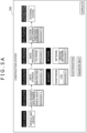
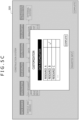
- FIG. 5A is a diagram of assistance in explaining a concrete example of the processing performed in step S102 in FIG. 3 .
- the system constructing device 100 presents, on the portal screen 210, a proposal of the system 281 that implements the functional requirement and the non-functional requirement input in step S101.
- the user 201 inputs information necessary to deploy the system 281 presented on the portal screen 210 (see FIG. 5B ). Further, the user 201 may change each infrastructure resource 283 to another infrastructure resource 283.
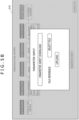
- FIG. 5B represents an example of a method of inputting the information necessary to deploy the system 281 presented on the portal screen 210 in step S103 in FIG. 3 .
- a screen 301 illustrated in FIG. 5B is displayed.
- an example is illustrated in which an excel sheet describing various kinds of parameters necessary to deploy infrastructure resources selected in FIG. 5A is uploaded as a parameter sheet, and the setting value 282 needed by each infrastructure resource 283 is input.
- FIG. 5C represents an example in a case of changing each service to another service in step S103 in FIG. 3 .
- a screen 320 of FIG. 5C is displayed.
- an example is illustrated in which a resource storing data is changed.
- the user selects another resource, a change is made to the resource selected by the user.
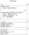
- FIG. 6 is a diagram illustrating an example of the system source code related to the deployment processing in step S104 and step S105 in FIG. 3 .
- Terrafrom is used for the deployment processing.
- Terraform is an open-source infrastructure automatic constructing tool developed by HashiCorp.
- the template 221 generally includes source code such as main.Tf (400) defining what kind of infrastructure resource 283 is to be deployed, a variable file in a format such as variables.Tf (410) defining variables to be given to each infrastructure resource 283 and default values of the variables, and a variable input file in a format such as auto.input.tfvars (420) defining the setting values 282 of the variables to be given to each infrastructure resource 283.
- source code such as main.Tf (400) defining what kind of infrastructure resource 283 is to be deployed
- a variable file in a format such as variables.Tf (410) defining variables to be given to each infrastructure resource 283 and default values of the variables
- a variable input file in a format such as auto.input.tfvars (420) defining the setting values 282 of the variables to be given to each infrastructure resource 283.
- a description 401 denotes that "aws_s3_bucket” is to be deployed as a resource.
- the template file may include a programmatic element, for example, an if statement.
- Terraform defines usable programmatic elements, and a variable count enables control as to how many resources are constructed.
- S3_count 1" is designated within auto.input.tfvars (420)
- one "resource "aws_s3_bucket” "s3_bucket ⁇ is generated.
- resources can be customized by controlling the count on the basis of the information input in FIG. 5B .
- the deploying section 240 deploy the infrastructure resource 283 in the execution environment 280 by using the deployment tool.
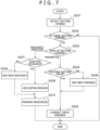
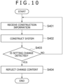
- FIG. 7 is a flowchart illustrating an example of a concrete processing procedure in step S106 and step S107 in FIG. 3 . In the following, each step of FIG. 7 will be described.
- the setting change detecting section 250 detects that the user 201 has directly changed the system 281 in the execution environment 280 (step S201).
- step S201 when the system 281 is constructed in step S105 in FIG. 3 , reference source code is obtained by using a function of exporting the system 281 prepared by a cloud vendor as the source code of each cloud vendor, and thereafter a difference between the source code obtained by the exporting function and the reference source code may be sequentially obtained.
- each cloud vendor prepares metadata indicating the same system 281 as a standard, and it is thereby possible to detect the addition of a new apparatus to the system 281.
- the above-described detection is made possible also by adding metadata indicating the same system when the system 281 is constructed in step S105 in FIG. 2 .
- step S202 the setting change detecting section 250 checks whether a setting change is detected.
- step S203 the processing proceeds to step S203.
- no setting change the processing is ended.
- the setting change detecting section 250 checks the kind of the setting change (step S203).
- the kind of the setting change there are two kinds of setting changes including a setting change related to the infrastructure resource 283 and a setting change related to the setting value 282 of the infrastructure resource 283.
- the setting change related to the setting value 282 of the infrastructure resource 283 represents a case of changing the setting value 282 of the infrastructure resource 283.
- the processing proceeds to step S207.
- the setting change related to the setting value 282 of the infrastructure resource 283 is detected, the processing proceeds to step S204.
- the setting value 282 referred to here is the parameters described in the parameter sheet illustrated in FIG. 5B .
- the setting change reflecting section 260 checks whether the setting change is a setting change related to an existing setting value 282 (step S204).
- the existing setting value 282 represents the setting value 282 already defined in the system source code.
- a VM Virtual Machine
- the VM refers to a virtual environment that is created on a physical hardware system (a location is off premises or on the premises), has its own CPU, memory, network interface, and storage, and functions as a virtual computer system.
- the size of the VM is set small in a part in which the VM is defined as system source code.
- the size of the VM is the setting value 282 already defined as the system source code, and is therefore judged to be an existing setting value 282.
- the setting value is a setting value 282 not defined as the system source code, and is therefore judged not to be an existing setting value 282.
- the processing proceeds to step S205.
- the processing otherwise proceeds to step S206.
- step S208 the processing proceeds to step S209.
- the setting change reflecting section 260 adds the existing infrastructure resource 283 to the system source code (step S208).
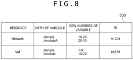
- the source code program of each infrastructure resource 283 registered in the repository 220 in advance is searched using the name of the added infrastructure resource 283 obtained as a difference. Then, the source code program of the identified infrastructure resource 283 is added to the system source code.
- the setting change is the deletion of a resource. In that case, it suffices to delete a part defining the corresponding resource within the source code program.
Landscapes
- Engineering & Computer Science (AREA)
- Software Systems (AREA)
- Theoretical Computer Science (AREA)
- General Engineering & Computer Science (AREA)
- Physics & Mathematics (AREA)
- General Physics & Mathematics (AREA)
- Computer Security & Cryptography (AREA)
- Stored Programmes (AREA)
Applications Claiming Priority (2)
| Application Number | Priority Date | Filing Date | Title |
|---|---|---|---|
| JP2022079548A JP7744294B2 (ja) | 2022-05-13 | 2022-05-13 | システム構築装置 |
| PCT/JP2023/015440 WO2023218875A1 (ja) | 2022-05-13 | 2023-04-18 | システム構築装置 |
Publications (2)
| Publication Number | Publication Date |
|---|---|
| EP4524722A1 true EP4524722A1 (de) | 2025-03-19 |
| EP4524722A4 EP4524722A4 (de) | 2026-04-22 |
Family
ID=88730261
Family Applications (1)
| Application Number | Title | Priority Date | Filing Date |
|---|---|---|---|
| EP23803357.5A Pending EP4524722A4 (de) | 2022-05-13 | 2023-04-18 | Systembauvorrichtung |
Country Status (5)
| Country | Link |
|---|---|
| US (1) | US20250190193A1 (de) |
| EP (1) | EP4524722A4 (de) |
| JP (1) | JP7744294B2 (de) |
| CN (1) | CN118633076A (de) |
| WO (1) | WO2023218875A1 (de) |
Families Citing this family (2)
| Publication number | Priority date | Publication date | Assignee | Title |
|---|---|---|---|---|
| JP7693130B1 (ja) * | 2024-05-30 | 2025-06-16 | 三菱電機株式会社 | アプリケーション管理システム、アプリケーション管理方法及びプログラム |
| US12541342B1 (en) * | 2025-10-09 | 2026-02-03 | ExlService Holdings, Inc. | Platform for automated infrastructure-as-code generation and deployment using multi-agent architecture |
Family Cites Families (7)
| Publication number | Priority date | Publication date | Assignee | Title |
|---|---|---|---|---|
| JP2006018735A (ja) * | 2004-07-05 | 2006-01-19 | Hitachi Software Eng Co Ltd | コーディング規準遵守状況監視システム |
| JP2006260165A (ja) | 2005-03-17 | 2006-09-28 | Ricoh Co Ltd | プログラムルールチェック装置 |
| JP4983027B2 (ja) | 2006-01-27 | 2012-07-25 | 富士通株式会社 | チェックプログラム及びチェック方法 |
| JP7077191B2 (ja) * | 2018-09-12 | 2022-05-30 | 株式会社日立製作所 | ビジュアルプログラミングツールを用いてフローを作成することを支援する装置および方法 |
| JP7231518B2 (ja) * | 2019-08-30 | 2023-03-01 | 株式会社日立製作所 | パッケージ化支援システムおよびパッケージ化支援方法 |
| JP7492839B2 (ja) | 2020-03-04 | 2024-05-30 | 三菱電機インフォメーションネットワーク株式会社 | 構成管理装置、構成管理方法、及び、構成管理プログラム |
| JP6920501B1 (ja) | 2020-03-27 | 2021-08-18 | ソフトバンク株式会社 | 情報処理システム、プログラム、及び情報処理方法 |
-
2022
- 2022-05-13 JP JP2022079548A patent/JP7744294B2/ja active Active
-
2023
- 2023-04-18 WO PCT/JP2023/015440 patent/WO2023218875A1/ja not_active Ceased
- 2023-04-18 EP EP23803357.5A patent/EP4524722A4/de active Pending
- 2023-04-18 US US18/842,447 patent/US20250190193A1/en active Pending
- 2023-04-18 CN CN202380019637.2A patent/CN118633076A/zh active Pending
Also Published As
| Publication number | Publication date |
|---|---|
| CN118633076A (zh) | 2024-09-10 |
| US20250190193A1 (en) | 2025-06-12 |
| EP4524722A4 (de) | 2026-04-22 |
| JP2023167974A (ja) | 2023-11-24 |
| JP7744294B2 (ja) | 2025-09-25 |
| WO2023218875A1 (ja) | 2023-11-16 |
Similar Documents
| Publication | Publication Date | Title |
|---|---|---|
| US11868231B2 (en) | System and method for evaluating code by a hybrid of local and cloud-based computers | |
| CN108304201B (zh) | 对象更新方法、装置及设备 | |
| US9606788B2 (en) | Dynamic update installer for customized software | |
| KR101999409B1 (ko) | 예시에 의한 데이터 포매팅 기법 | |
| US11714625B2 (en) | Generating applications for versatile platform deployment | |
| US20200384644A1 (en) | Systems and Methods for Robotic Process Automation | |
| CN111104103B (zh) | 一种软件编辑微服务的可视化方法及系统 | |
| EP4524722A1 (de) | Systembauvorrichtung | |
| CN113760266B (zh) | 一种功能模块文件的创建方法、创建装置和电子设备 | |
| US20140033123A1 (en) | User interface and method for comparing a local version of a profile to an online update | |
| CN106406999A (zh) | 计算系统和计算系统的执行控制方法 | |
| CN112948264B (zh) | 测试任务的执行方法及装置、系统、存储介质、电子装置 | |
| US20160274906A1 (en) | Generating a deployable industry-specific solution package | |
| WO2024244727A1 (zh) | 一种应用打包方法、装置、设备及存储介质 | |
| CN115629763A (zh) | 目标代码的生成方法、npu指令的显示方法及装置 | |
| CN111722881B (zh) | 一种容器云平台的资源扩展方法、系统及装置 | |
| CN111427770B (zh) | 一种资源测试方法及相关设备 | |
| CN119759337A (zh) | 基于低代码平台的应用程序构建方法、低代码平台、计算机设备及可读存储介质 | |
| US12045584B2 (en) | Undeployed topology visualization for improving software application development | |
| CN117035664A (zh) | 基于模板的授信审批标准化处理方法、装置、设备及介质 | |
| CN117806633A (zh) | 页面交互事件配置方法、装置、计算机设备及存储介质 | |
| WO2023151397A1 (zh) | 应用程序部署方法、装置、设备及介质 | |
| CN113900742A (zh) | 应用实例的管理方法、装置、电子设备及存储介质 | |
| CN115248680B (zh) | 软件构建方法、系统、设备、介质和程序产品 | |
| CN115904334B (zh) | 代码处理方法、装置、计算机设备及存储介质 |
Legal Events
| Date | Code | Title | Description |
|---|---|---|---|
| STAA | Information on the status of an ep patent application or granted ep patent |
Free format text: STATUS: THE INTERNATIONAL PUBLICATION HAS BEEN MADE |
|
| PUAI | Public reference made under article 153(3) epc to a published international application that has entered the european phase |
Free format text: ORIGINAL CODE: 0009012 |
|
| STAA | Information on the status of an ep patent application or granted ep patent |
Free format text: STATUS: REQUEST FOR EXAMINATION WAS MADE |
|
| 17P | Request for examination filed |
Effective date: 20241213 |
|
| AK | Designated contracting states |
Kind code of ref document: A1 Designated state(s): AL AT BE BG CH CY CZ DE DK EE ES FI FR GB GR HR HU IE IS IT LI LT LU LV MC ME MK MT NL NO PL PT RO RS SE SI SK SM TR |
|
| DAV | Request for validation of the european patent (deleted) | ||
| DAX | Request for extension of the european patent (deleted) | ||
| RAP3 | Party data changed (applicant data changed or rights of an application transferred) |
Owner name: ASTEMO, LTD. |
|
| REG | Reference to a national code |
Ref country code: DE Ref legal event code: R079 Free format text: PREVIOUS MAIN CLASS: G06F0008300000 Ipc: G06F0008600000 |
|
| A4 | Supplementary search report drawn up and despatched |
Effective date: 20260325 |
|
| RIC1 | Information provided on ipc code assigned before grant |
Ipc: G06F 8/60 20180101AFI20260319BHEP Ipc: G06F 9/445 20180101ALI20260319BHEP Ipc: G06F 8/71 20180101ALI20260319BHEP Ipc: G06F 8/30 20180101ALN20260319BHEP Ipc: G06F 9/455 20180101ALN20260319BHEP |