EP4524660A2 - Verfahren zur linsenfreien holographischen in-line-bildgebung von objekten in einem tröpfchen - Google Patents
Verfahren zur linsenfreien holographischen in-line-bildgebung von objekten in einem tröpfchen Download PDFInfo
- Publication number
- EP4524660A2 EP4524660A2 EP24194852.0A EP24194852A EP4524660A2 EP 4524660 A2 EP4524660 A2 EP 4524660A2 EP 24194852 A EP24194852 A EP 24194852A EP 4524660 A2 EP4524660 A2 EP 4524660A2
- Authority
- EP
- European Patent Office
- Prior art keywords
- droplet
- artifact
- objects
- hologram
- image
- Prior art date
- Legal status (The legal status is an assumption and is not a legal conclusion. Google has not performed a legal analysis and makes no representation as to the accuracy of the status listed.)
- Pending
Links
Images






Classifications
-
- G—PHYSICS
- G03—PHOTOGRAPHY; CINEMATOGRAPHY; ANALOGOUS TECHNIQUES USING WAVES OTHER THAN OPTICAL WAVES; ELECTROGRAPHY; HOLOGRAPHY
- G03H—HOLOGRAPHIC PROCESSES OR APPARATUS
- G03H1/00—Holographic processes or apparatus using light, infrared or ultraviolet waves for obtaining holograms or for obtaining an image from them; Details peculiar thereto
- G03H1/04—Processes or apparatus for producing holograms
- G03H1/08—Synthesising holograms, i.e. holograms synthesized from objects or objects from holograms
- G03H1/0808—Methods of numerical synthesis, e.g. coherent ray tracing [CRT], diffraction specific
-
- G—PHYSICS
- G03—PHOTOGRAPHY; CINEMATOGRAPHY; ANALOGOUS TECHNIQUES USING WAVES OTHER THAN OPTICAL WAVES; ELECTROGRAPHY; HOLOGRAPHY
- G03H—HOLOGRAPHIC PROCESSES OR APPARATUS
- G03H1/00—Holographic processes or apparatus using light, infrared or ultraviolet waves for obtaining holograms or for obtaining an image from them; Details peculiar thereto
- G03H1/22—Processes or apparatus for obtaining an optical image from holograms
-
- G—PHYSICS
- G01—MEASURING; TESTING
- G01N—INVESTIGATING OR ANALYSING MATERIALS BY DETERMINING THEIR CHEMICAL OR PHYSICAL PROPERTIES
- G01N15/00—Investigating characteristics of particles; Investigating permeability, pore-volume or surface-area of porous materials
- G01N15/02—Investigating particle size or size distribution
- G01N15/0205—Investigating particle size or size distribution by optical means
- G01N15/0227—Investigating particle size or size distribution by optical means using imaging; using holography
-
- G—PHYSICS
- G03—PHOTOGRAPHY; CINEMATOGRAPHY; ANALOGOUS TECHNIQUES USING WAVES OTHER THAN OPTICAL WAVES; ELECTROGRAPHY; HOLOGRAPHY
- G03H—HOLOGRAPHIC PROCESSES OR APPARATUS
- G03H1/00—Holographic processes or apparatus using light, infrared or ultraviolet waves for obtaining holograms or for obtaining an image from them; Details peculiar thereto
- G03H1/04—Processes or apparatus for producing holograms
- G03H1/0443—Digital holography, i.e. recording holograms with digital recording means
-
- G—PHYSICS
- G03—PHOTOGRAPHY; CINEMATOGRAPHY; ANALOGOUS TECHNIQUES USING WAVES OTHER THAN OPTICAL WAVES; ELECTROGRAPHY; HOLOGRAPHY
- G03H—HOLOGRAPHIC PROCESSES OR APPARATUS
- G03H1/00—Holographic processes or apparatus using light, infrared or ultraviolet waves for obtaining holograms or for obtaining an image from them; Details peculiar thereto
- G03H1/04—Processes or apparatus for producing holograms
- G03H1/08—Synthesising holograms, i.e. holograms synthesized from objects or objects from holograms
-
- G—PHYSICS
- G03—PHOTOGRAPHY; CINEMATOGRAPHY; ANALOGOUS TECHNIQUES USING WAVES OTHER THAN OPTICAL WAVES; ELECTROGRAPHY; HOLOGRAPHY
- G03H—HOLOGRAPHIC PROCESSES OR APPARATUS
- G03H1/00—Holographic processes or apparatus using light, infrared or ultraviolet waves for obtaining holograms or for obtaining an image from them; Details peculiar thereto
- G03H1/04—Processes or apparatus for producing holograms
- G03H1/08—Synthesising holograms, i.e. holograms synthesized from objects or objects from holograms
- G03H1/0866—Digital holographic imaging, i.e. synthesizing holobjects from holograms
-
- G—PHYSICS
- G06—COMPUTING OR CALCULATING; COUNTING
- G06N—COMPUTING ARRANGEMENTS BASED ON SPECIFIC COMPUTATIONAL MODELS
- G06N3/00—Computing arrangements based on biological models
- G06N3/02—Neural networks
- G06N3/04—Architecture, e.g. interconnection topology
- G06N3/045—Combinations of networks
-
- G—PHYSICS
- G06—COMPUTING OR CALCULATING; COUNTING
- G06V—IMAGE OR VIDEO RECOGNITION OR UNDERSTANDING
- G06V10/00—Arrangements for image or video recognition or understanding
- G06V10/10—Image acquisition
- G06V10/12—Details of acquisition arrangements; Constructional details thereof
- G06V10/14—Optical characteristics of the device performing the acquisition or on the illumination arrangements
-
- G—PHYSICS
- G06—COMPUTING OR CALCULATING; COUNTING
- G06V—IMAGE OR VIDEO RECOGNITION OR UNDERSTANDING
- G06V10/00—Arrangements for image or video recognition or understanding
- G06V10/70—Arrangements for image or video recognition or understanding using pattern recognition or machine learning
- G06V10/82—Arrangements for image or video recognition or understanding using pattern recognition or machine learning using neural networks
-
- G—PHYSICS
- G06—COMPUTING OR CALCULATING; COUNTING
- G06V—IMAGE OR VIDEO RECOGNITION OR UNDERSTANDING
- G06V20/00—Scenes; Scene-specific elements
- G06V20/60—Type of objects
- G06V20/64—Three-dimensional [3D] objects
-
- G—PHYSICS
- G01—MEASURING; TESTING
- G01N—INVESTIGATING OR ANALYSING MATERIALS BY DETERMINING THEIR CHEMICAL OR PHYSICAL PROPERTIES
- G01N15/00—Investigating characteristics of particles; Investigating permeability, pore-volume or surface-area of porous materials
- G01N15/10—Investigating individual particles
- G01N15/14—Optical investigation techniques, e.g. flow cytometry
- G01N15/1434—Optical arrangements
- G01N2015/1454—Optical arrangements using phase shift or interference, e.g. for improving contrast
-
- G—PHYSICS
- G03—PHOTOGRAPHY; CINEMATOGRAPHY; ANALOGOUS TECHNIQUES USING WAVES OTHER THAN OPTICAL WAVES; ELECTROGRAPHY; HOLOGRAPHY
- G03H—HOLOGRAPHIC PROCESSES OR APPARATUS
- G03H1/00—Holographic processes or apparatus using light, infrared or ultraviolet waves for obtaining holograms or for obtaining an image from them; Details peculiar thereto
- G03H1/0005—Adaptation of holography to specific applications
- G03H2001/0033—Adaptation of holography to specific applications in hologrammetry for measuring or analysing
- G03H2001/0038—Adaptation of holography to specific applications in hologrammetry for measuring or analysing analogue or digital holobjects
-
- G—PHYSICS
- G03—PHOTOGRAPHY; CINEMATOGRAPHY; ANALOGOUS TECHNIQUES USING WAVES OTHER THAN OPTICAL WAVES; ELECTROGRAPHY; HOLOGRAPHY
- G03H—HOLOGRAPHIC PROCESSES OR APPARATUS
- G03H1/00—Holographic processes or apparatus using light, infrared or ultraviolet waves for obtaining holograms or for obtaining an image from them; Details peculiar thereto
- G03H1/0005—Adaptation of holography to specific applications
- G03H2001/005—Adaptation of holography to specific applications in microscopy, e.g. digital holographic microscope [DHM]
-
- G—PHYSICS
- G03—PHOTOGRAPHY; CINEMATOGRAPHY; ANALOGOUS TECHNIQUES USING WAVES OTHER THAN OPTICAL WAVES; ELECTROGRAPHY; HOLOGRAPHY
- G03H—HOLOGRAPHIC PROCESSES OR APPARATUS
- G03H1/00—Holographic processes or apparatus using light, infrared or ultraviolet waves for obtaining holograms or for obtaining an image from them; Details peculiar thereto
- G03H1/04—Processes or apparatus for producing holograms
- G03H1/08—Synthesising holograms, i.e. holograms synthesized from objects or objects from holograms
- G03H1/0808—Methods of numerical synthesis, e.g. coherent ray tracing [CRT], diffraction specific
- G03H2001/0816—Iterative algorithms
-
- G—PHYSICS
- G03—PHOTOGRAPHY; CINEMATOGRAPHY; ANALOGOUS TECHNIQUES USING WAVES OTHER THAN OPTICAL WAVES; ELECTROGRAPHY; HOLOGRAPHY
- G03H—HOLOGRAPHIC PROCESSES OR APPARATUS
- G03H1/00—Holographic processes or apparatus using light, infrared or ultraviolet waves for obtaining holograms or for obtaining an image from them; Details peculiar thereto
- G03H1/04—Processes or apparatus for producing holograms
- G03H1/08—Synthesising holograms, i.e. holograms synthesized from objects or objects from holograms
- G03H1/0808—Methods of numerical synthesis, e.g. coherent ray tracing [CRT], diffraction specific
- G03H2001/0825—Numerical processing in hologram space, e.g. combination of the CGH [computer generated hologram] with a numerical optical element
-
- G—PHYSICS
- G03—PHOTOGRAPHY; CINEMATOGRAPHY; ANALOGOUS TECHNIQUES USING WAVES OTHER THAN OPTICAL WAVES; ELECTROGRAPHY; HOLOGRAPHY
- G03H—HOLOGRAPHIC PROCESSES OR APPARATUS
- G03H1/00—Holographic processes or apparatus using light, infrared or ultraviolet waves for obtaining holograms or for obtaining an image from them; Details peculiar thereto
- G03H1/04—Processes or apparatus for producing holograms
- G03H1/08—Synthesising holograms, i.e. holograms synthesized from objects or objects from holograms
- G03H1/0866—Digital holographic imaging, i.e. synthesizing holobjects from holograms
- G03H2001/0883—Reconstruction aspect, e.g. numerical focusing
-
- G—PHYSICS
- G03—PHOTOGRAPHY; CINEMATOGRAPHY; ANALOGOUS TECHNIQUES USING WAVES OTHER THAN OPTICAL WAVES; ELECTROGRAPHY; HOLOGRAPHY
- G03H—HOLOGRAPHIC PROCESSES OR APPARATUS
- G03H1/00—Holographic processes or apparatus using light, infrared or ultraviolet waves for obtaining holograms or for obtaining an image from them; Details peculiar thereto
- G03H1/26—Processes or apparatus specially adapted to produce multiple sub- holograms or to obtain images from them, e.g. multicolour technique
- G03H1/2645—Multiplexing processes, e.g. aperture, shift, or wavefront multiplexing
- G03H2001/266—Wavelength multiplexing
-
- G—PHYSICS
- G03—PHOTOGRAPHY; CINEMATOGRAPHY; ANALOGOUS TECHNIQUES USING WAVES OTHER THAN OPTICAL WAVES; ELECTROGRAPHY; HOLOGRAPHY
- G03H—HOLOGRAPHIC PROCESSES OR APPARATUS
- G03H2210/00—Object characteristics
- G03H2210/62—Moving object
-
- G—PHYSICS
- G03—PHOTOGRAPHY; CINEMATOGRAPHY; ANALOGOUS TECHNIQUES USING WAVES OTHER THAN OPTICAL WAVES; ELECTROGRAPHY; HOLOGRAPHY
- G03H—HOLOGRAPHIC PROCESSES OR APPARATUS
- G03H2210/00—Object characteristics
- G03H2210/63—Environment affecting the recording, e.g. underwater
-
- G—PHYSICS
- G03—PHOTOGRAPHY; CINEMATOGRAPHY; ANALOGOUS TECHNIQUES USING WAVES OTHER THAN OPTICAL WAVES; ELECTROGRAPHY; HOLOGRAPHY
- G03H—HOLOGRAPHIC PROCESSES OR APPARATUS
- G03H2222/00—Light sources or light beam properties
- G03H2222/40—Particular irradiation beam not otherwise provided for
- G03H2222/44—Beam irradiating the object at recording stage
Definitions
- the present disclosure relates to holographic imaging and image processing.
- the disclosure is concerned with in-line lens-free holographic imaging of at least one or more objects contained inside a droplet.
- the disclosure thus proposes a method and an apparatus for imaging the one or more objects in the droplet.
- the disclosure also proposes methods for recognizing at least one characteristic of the one or more objects contained in the droplet.
- imaging is an important method to extract information, for instance, one or more characteristics of the object.
- the imaging of such objects within droplets currently relies mainly on microscopic techniques.
- Holographic imaging may provide a compact, high-throughput imaging method, but has been applied only to analyze isolated droplets, but not objects inside of droplets. This is mainly due to the fact, that there are major problems when this imaging technique is applied to such a case.
- One problem is that lensing effects, which are caused by the droplet, distort the illumination wavefront and thus cause information loss.
- Another problem is that artifacts appear in the holograms or images, which affect the quality of the objects inside the droplets.
- Holographic imaging of an object may be performed using either in-line transmission or off-axis reflection holography.
- Off-axis holographic imaging uses a reference beam with a non-zero angle with respect to a signal beam. With this technique, both the amplitude and the phase of the object can be retrieved by digital reconstruction methods.
- off-axis holographic imaging has a limited field of view, because of the needed reference beam. In particular, there needs to be enough space to allow the reference beam to reach the entire sensor of the holographic imager.
- In-line holographic imaging has only one optical path, and thus offers a simpler setup, easier alignment, and a more compact design compared to off-axis holographic imaging.
- In-line holographic imaging there is no need for a reference beam, and thus no field of view limitation.
- In-line holographic imaging may also be lens-free, due to the single optical path.
- the phase information is not available. Because of this, the phase retrieval during image reconstruction of the hologram is different, and also any kind of artifact suppression - which is essential for imaging objects inside of droplets - becomes different.
- this disclosure aims to provide a solution to use in-line lens free holographic imaging of objects contained within droplets.
- An objective is to avoid and/or remove any artifacts in the hologram and/or image, and thus to obtain high-quality images of the objects in the droplets.
- a first aspect of this disclosure provides a method for imaging and recognizing at least one characteristic of one or more objects contained in a droplet, the method comprising: generating at least one hologram of the one or more objects contained in the droplet, wherein the at least one hologram is generated using in-line lens-free imaging; wherein the at least one hologram includes at least one artifact, which is at least caused by the presence of the droplet and affects the at least one characteristic of the one or more objects contained in the droplet; removing fully or partially the at least one artifact or the cause of the at least one artifact; generating an image, after or during removing the at least one artifact or the cause of the at least one artifact, comprising the one or more objects; and recognizing the at least one characteristic of the one or more objects based on the image.
- the present disclosure realizes that many artifacts are caused by the presence of the droplet, and understands the underlying mechanisms that cause the artifacts.
- the solutions of this disclosure can take into account such artifacts or causes of artifacts, which arise due to the fact that the objects are enclosed in a droplet.
- the method of the first aspect allows removing, or avoiding in the first place, such artifacts, which are caused by the presence of the droplet.
- the method of the first aspect can use in-line lens free imaging to image the one or more objects inside the droplet.
- the in-line lens free holographic imaging used in the method of the first aspect is based on the assumption that light going through the droplet has a certain portion that is not scattered by the object in the droplet.
- the method of the first aspect is thus able to obtain high-quality holographic (and reconstructed) images of the objects, even though the objects are contained in the droplets.
- Morphological information refers to data about the shape, structure, and/or form of the objects, and may generally be referred to as physical characteristics of the objects. Obtaining such morphological information may enable analyzing and quantifying the shape and structure of the one or more objects within the droplet, and may thus allow object recognition, or the like.
- the one or more objects inside the droplet are unknown regarding their characteristics, before the method is performed.
- some conventional imaging techniques using off-axis holographic imaging assume the objects to be in principle known, for instance, their material, dimensions, etc. In this case, known thresholds of different parts in the frequency domain may be used to remove unwanted signals or noise.
- the in-line lens-free holographic imaging used in the method of the first aspect also leads to a simpler setup for imaging the one or more objects within the droplet, easier alignment, and/or a more compact design than achievable with off-axis holographic imaging.
- the method of the first aspect further additionally allows recognizing the one or more characteristics of the object, including its physical characteristics like size and shape, which were or would have been fully suppressed by the at least one artifact.
- the method also allows recognizing one or more characteristic of the object, which were or would have been partly suppressed by the at least one artifact, and were already made more recognizable iterations of the method of the first aspect.
- the recognizing of the at least one characteristic is enabled by the improved hologram and image quality, because of the at least partly removed artifact.
- the one or more objects together with the one or more droplets, in which they are contained may be referred to as one or more samples.
- a sample may, for instance, refer to one or a group of droplets with relevant objects inside, particularly, on a fluidic carrier.
- the method may be useful for imaging samples.
- the objects may be any kind of material particles or biological material, like cells, DNA, living organisms like bacteria, etc.
- the droplets may be made of a liquid, for instance, water, oil, or any other suitable carrier liquid for the objects.
- the at least one artifact comprises: an interference in the hologram of a first holographic signal of the droplet and one or more second holographic signals of the one or more objects; and/or noise in the first holographic signal of the droplet and/or the one or more second holographic signals of the one or more objects.
- the presence of the droplet may cause certain artifacts (e.g., ring-like artifacts) in the holographic image of the object inside the droplet by various physical mechanisms.
- the artifacts may generally be caused by the interaction of the hologram signatures (i.e., holographic signals) of the droplet and the object inside the droplet.
- the surface of the droplet may cause a lensing effect, which may lead at least to a distortion of the holographic signal of the object inside the droplet, and may even lead to the holographic signal of the object being lost.
- the holographic signal of the droplet may interfere with the holographic signal of the object.
- the droplet may cause an uneven illumination intensity, like local darkness and local saturation on a sensor used to obtain the holographic image. The understanding of these kinds of mechanisms allows an efficient removal or suppression of the artifacts.
- removing the at least one artifact or the cause of the at least one artifact comprises regenerating the at least one hologram of the one or more objects contained in the droplet, wherein a second illumination wavefront is used for regenerating the at least one hologram, which is different from a first illumination wavefront that was used for generating the at least one hologram.
- This implementation uses wavefront engineering to remove the artifacts, in particular, to suppress a cause of the artifacts.
- wavefront engineering uses wavefront engineering to remove the artifacts, in particular, to suppress a cause of the artifacts.
- the wavefront of the illumination may be adjusted to compensate the distortion caused by the droplet. For instance, by adjusting the wavefront curvature with an optical component.
- the wavefront engineering may advantageously be applied for the removal.
- the second illumination wavefront comprises a single wavelength or multiple wavelengths.
- removing the at least one artifact or the cause of the at least one artifact comprises processing the at least one hologram with one or more numerical optimization algorithms, such as a fast iterative shrinkage-thresholding (FISTA) algorithm or an Alternating Direction Method of Multipliers (ADMM) algorithm.
- FISTA fast iterative shrinkage-thresholding
- ADMM Alternating Direction Method of Multipliers
- removing the at least one artifact or the cause of the at least one artifact comprises processing the at least one hologram by at least one image processing method.
- the at least one image processing method may include one or more of the following: image correction, image transformation, image operations including blending, histograms, moments, feature detection, feature extraction, simulation, thresholding, object detection, classification methods, machine learning, and deep learning.
- Feature extraction methods may also be used to derive or calculate one or more characteristics or features of the one or more objects.
- machine learning methods may be used for the at least one image processing method.
- removing the at least one artifact or the cause of the at least one artifact comprises generating the image by multi-depth reconstruction of the at least one hologram.
- the multi-depth reconstruction may advantageously be used.
- the method further comprises: determining a strength of the at least one artifact; and selecting how to remove the at least one artifact or the cause of the at least one artifact based on the determined strength.
- one or more of the previously described techniques for removing the at least one artifact or the cause of the at least one artifact may be used. That is, depending on the determined strength, one or more of: wavefront engineering, FISTA or ADMM processing, image processing, or multi-depth reconstruction may be applied.
- the strength of the at least one artifact is determined by comparing at least one parameter of the one or more objects in the at least one hologram and in at least one reference hologram of the one or more objects without droplet.
- the at least one characteristic of the one or more objects comprises at least one of the following: a number of the one or more objects contained in the droplet; a density of the one or more objects in the droplet; a respective size and/or shape of each object of the one or more objects in the droplet; a respective position of each object of the one or more objects in the droplet; a motion pattern of the one or more objects in the droplet; a reflective index of the one or more objects in the droplet.
- a second aspect of this disclosure provides an apparatus for imaging and recognizing at least one characteristic of one or more objects contained in a droplet, the apparatus comprising: a holographic imager configured to generate at least one hologram of the one or more objects contained in the droplet using in-line lens-free imaging; wherein the at least one hologram includes at least one artifact, which is at least caused by the presence of the droplet and affects the at least one characteristic of the one or more objects in the droplet; and a processor configured to remove fully or partially the at least one artifact or the cause of the at least one artifact; wherein the processor is further configured to generate an image, after or during removing the at least one artifact or the cause of the at least one artifact, comprising the one or more objects, and to recognize the at least one characteristic of the one or more objects based on the image.
- the apparatus of the second aspect may have implementations that correspond to the implementations of the method of the first aspect.
- the apparatus of the second aspect may provide similar advantages as described above for the method of the first aspect and its implementations.
- the processor of the apparatus may be configured to control the holographic imager to obtain the second hologram by in-line lens-free imaging, and to generate the image.
- the processor may also be configured to process the hologram and/or to process the image.
- a third aspect of this disclosure provides a computer-implemented method for recognizing at least one characteristic of one or more objects contained in a droplet, the method comprising: obtaining at least one hologram of the one or more objects contained in the droplet, wherein the at least one hologram has been previously generated using in-line lens-free imaging; wherein the at least one hologram includes at least one artifact, which is at least caused by the presence of the droplet and affects the at least one characteristic of the one or more objects contained in the droplet; processing the at least one hologram using a computational model, wherein the computational model removes fully or partially the at least one artifact; generating an image, after or during removing the at least one artifact, comprising the one or more objects; and recognizing the at least one characteristic of the one or more objects based on the image.
- the method of the third aspect may have implementations that correspond to the implementations of the method of the first aspect.
- the method of the third aspect may provide similar advantages as described above for the method of the first aspect and its implementations.
- the steps of "generating” and “recognizing” could be done by the computational model as well. That is, at least the artifact removal step is done with the use of the computational model.
- the computational model is a deep learning neural network (DNN).
- DNN deep learning neural network
- the DNN is a derived method based on convolutional neural network (CNN).
- CNN convolutional neural network
- the DNN may be trained to enable it to remove the at least one artifact or the cause of the at least one artifact efficiently.
- the training may be performed using a dataset, in particular, a simulated dataset; in another embodiment, the dataset can be real-world data. Training parameters and procedures are described later.
- a fourth aspect of this disclosure provides a computer program comprising instructions which, when the program is executed by a processor, for example the processor of the apparatus of claim 12, causes the processor to perform the method according to the third aspect.
- this disclosure addresses the challenging problem of generating high-quality images of objects inside droplets.
- the droplets and objects can introduce many kinds of artifacts.
- the disclosure proposes holographic imaging using in-line lens-free imaging, and a meta-pipeline to see the objects inside droplets more clearly.
- the disclosure proposes both hardware-based and software-based aspects of the solution, which maybe applied depending on, for example, different kinds or levels of artifacts that are caused by different underlying mechanisms.
- subsequent processing steps like the detection of the one or more characteristics of the objects, a classification of objects (e.g. based on the characteristics), and a tracking of the objects (e.g. based on the characteristics), can be performed. This enables a broader range of applications, like cell treatments, bacterial culturing, etc.
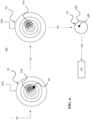
- FIG. 1 illustrates schematically a holographic imaging of an object 11 in a droplet 12.
- FIG. 1 shows on the top a physical shape of the droplet 12 without any object 11 inside, of an object 11 without droplet 12, and of the droplet 12 including the object 11 inside. Then, in the middle of FIG. 1 , the respective holograms after holographic imaging said physical shapes are illustrated.
- the droplet 12 alone results in a holographic signal 12a (left, e.g. referred to as a first ring pattern), the object 11 alone results in a holographic signal 11a (middle, e.g.
- a second ring pattern referred to as a second ring pattern
- the combination of the droplet 12 and the object 11 in the droplet 12 results in a hologram 13 (right) based on a complex interaction of the two ideal holographic signals 11a, 12a (e.g., interactions of the first and second ring pattern).
- the respective holograms 13 can be reconstructed, wherein ideal reconstruction is assumed.
- the bottom of FIG. 1 shows images resulting from the reconstruction. In particular, the image 12b of only the droplet 12, the image 11b of only the object 11, and the combined image of the droplet 12 and object 11 are shown. Under ideal circumstances, these images resemble the physical shapes of the droplet 12 and object 11.
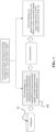
- FIG. 2 shows a method 20 according to this disclosure for imaging and recognizing at least one characteristic 25 of an object 11 contained in a droplet 12, wherein the method 20 can cope with such artifacts.
- the method 20 further comprises a step 22 of removing fully or partially the at least one artifact 14, or the cause of the at least one artifact 14. Different ways to remove the artifact 14 or the cause of the artifact 14 are described later.
- the method 20 further comprises a step 23 of generating an image 15 after or during removing the at least one artifact 14 or the cause of the at least one artifact 14.
- the image 15 may be generated by reconstruction of the hologram 13 after artifact removal, for example, by reconstruction methods known in the art.
- the image 15 comprises the object 11, and may comprise the droplet 12 as shown in FIG. 2 . In another embodiment, the image 15 comprises the object 11 where the droplet 12 and the artifact are both removed.
- the method 20 then comprises a step 24 of recognizing the at least one characteristic 25 of the object 11 based on the image 15, wherein the determination of the characteristic 25 is not anymore prevented of made difficult by the artifact 14.
- the at least one characteristic 25 may be directly derived from the image 15, for instance, if the characteristic is a shape or size or location or the like. Other characteristics 25 could be obtained by post-processing the image 15.
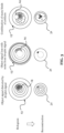
- FIG. 3 illustrates some possible causes of artifacts 14, which affect the object 11-particularly make it difficult to derive the characteristic(s) 25 - and are caused by the presence of the droplet 12.
- an artifact 14 may be caused by an interference in the hologram 13 of the holographic signal 12a of the droplet 12 and the holographic signal 11a of the object 11 (e.g., interference of the first and second ring patterns). This is shown on the left side of FIG. 3 , wherein the object signal is distorted by the droplet signal. This may also lead to an artifact in an image 31, after reconstruction of the hologram 13.
- noise in the holographic signal 12a of the droplet 12 and/or noise in the holographic signal 11a of the object 11 may cause an artifact 14.
- an object signal loss may be caused with the noise from the droplet signal (e.g., the first ring pattern). This will result in loss of information of the object 11 in the image 31 as well.
- ring-like artifacts 14 caused by the droplet 12 may come from the unknown phase of the hologram, which is due to the in-line lens-free holographic imaging used in this disclosure. These artifacts 14 may occupy most of the area inside the droplet 12. For removing the artifact 14, the first ring pattern from the droplet 12 may thus be removed.
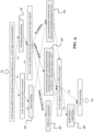
- FIG. 4 shows an exemplary pipeline according to this disclosure, also referred to as meta-pipeline, for removing at least one artifact 14 or the cause of the at least one artifact 14 from a hologram 13.
- the pipeline is applicable for both single and multi-wavelengths in-line lens-free holographic imaging.
- multi-aperture can be also considered to be a special case of multi-wavelengths.
- the pipeline may provide various methods for removing the at least one artifact 14 or the cause of the at least one artifact 14.
- the pipeline may offer wave front engineering 41, deep learning filtering 42, a FISTA algorithm or a similar algorithm, conventional image and signal processing 44, and multi-depths reconstruction 46 as possible methods to remove the artifact 14.
- One or more of the various methods may be selected, for instance, depending on the type of the at least one artifact 14 and/or based on environmental conditions.
- the hologram 13 is input into the pipeline.
- the exemplary pipeline considers, whether a lensing effect of the droplet 12 causes information loss, for example, at the edge or of local saturation. If this is the case, then wavefront engineering 41 may be selected.
- the pipeline further considers whether the at least one artifact 14 and the object 11 are consistent. If yes, then deep learning 42 can be applied.
- any reconstruction method 45 - e.g. as conventionally described in the literature - can be applied to reconstruct the image 15 from the hologram 13.
- the pipeline may further consider, how the artifact 14 caused by the droplet 12 is compared to the object signal. Exemplary possibilities here are “strong or not regular”, “weak or regular”, or “no artifacts”. If there are no artifacts 14, the conventional reconstruction 45 can be used as described above.
- the FISTA algorithm 43 can be applied.
- conventional image and signal processing 44 may be applied, and may be sufficient to remove such artifacts 14.
- the pipeline may further consider whether there are objects 11 or droplets 12 at different heights/depth of the imaging direction. If yes, then multi-depths reconstruction 46 can be applied, which may be followed by post-processing afterwards, so as to output the final image 15. If not, then the post-processing can be applied directly.
- FIG. 5 compares various methods of removing the at least one artifact 14 or the cause of the at least one artifact 14 from the hologram 13, as shown in FIG. 4 .
- FIG. 5 evaluates a trade-off between a strength of improvement of the respective method (on the y-axis) and effort, e.g., computational or physical, of the respective method (on the x-axis).
- the strength of the at least one artifact 14 may be determined by comparing at least one parameter of the object 11 in the hologram 13 (with the droplet 12) and in at least one reference hologram of the object 11 without droplet 12.
- the FISTA algorithm 43 may be performed iteratively, in order remove unwanted signals and artifacts 14 of different kinds form the hologram 13.
- the FISTA algorithm 43 itself is known, compare e.g., " Fast compressive lens-free tomography for 3D biological cell culture imaging" Luo, Zhenxiang, et al., Optics Express 28.18 (2020): 26935-26952 .
- regular pre-processing steps may be applied to the hologram 13, for instance, illumination balancing.
- a high-quality reconstruction may be performed to obtain the image 15.
- FIG. 7 shows a conventional image and signal processing for removing weaker artifacts 14 from the hologram 13.
- the method 20 comprises, in this case, removing 22 the at least one artifact 14 or the cause of the at least one artifact 14 by processing the at least one hologram 13 by at least one image processing method 44.
- the image processing method 44 may comprise denoising, local illumination balancing and enhancement, using filters to remove unwanted signals, wavelet transfer etc.
- a reconstruction may be made of the hologram 13 to obtain the image 15.
- conventional image processing methods may be applied to the image 15. These may include signal or image enhancement, filters to remove unwanted signals, image engineering to detect artifacts and remove them.
- FIG. 8 illustrates wavefront engineering 41 to remove causes of artifacts 14.
- the method 20 comprises, in this case, a step of regenerating the hologram 13 of the objects 11 contained in the droplet 12 using in-line lens-free holographic imaging, wherein a second illumination wavefront is used for regenerating the hologram 13.
- the second illumination wavefront is different from a first illumination wavefront that was used for generating 23 the hologram 13.
- the second illumination wavefront comprises a single wavelength or multiple wavelengths.
- FIG. 8(a) shows examples in case of a normal illumination during the in-line lens-free holographic imaging.
- FIG. 8(a) shows on the left side an example of a droplet 12 of a non-polar material in a medium of a polar material, e.g., an oil droplet 12 in water.
- FIG. 8(a) shows on the right side an example of a droplet 12 of a polar material in a medium of a non-polar material, e.g., a water droplet 12 in oil. Lensing effects of the droplet 12 are illustrated by the arrows after the droplet 12.
- FIG. 8(a) shows on the left side an example of a droplet 12 of a non-polar material in a medium of a polar material, e.g., an oil droplet 12 in water.
- FIG. 8(a) shows on the right side an example of a droplet 12 of a polar material in a medium of a non-polar material, e.g.,
- lensing effects are due to the different materials (e.g. oil and water). However, as shown at the bottom of FIG. 8 , lensing effects are also a concern for certain droplet shapes, e.g., for flat droplets 12.
- FIG. 9 illustrates a method using multi-depths reconstruction for removing artifacts 14 from the hologram 13.
- the method 10 comprises, in this case, as step of generating the image 15 by multi-depth reconstruction 46 of the at least one hologram 13 obtained by in-line lens-free holographic imaging. That means the reconstruction of the hologram 13 is performed at multiple depths (in direction of the imaging, i.e., illumination wavefront), so that a projection onto the planar image 15 is achieved.
- the multi-depths reconstruction can also be applied to single droplet/object levels.
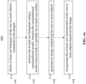
- FIG. 10 shows a flow-diagram of a computer-implemented method 100 according to this disclosure.
- the method 100 is for recognizing at least one characteristic 25 of one or more objects 11 contained in a droplet 12.
- the method 100 is in parts similar to the method 20.
- the method 100 comprises a step 101 of obtaining at least one hologram 13 of the one or more objects 11 contained in the droplet 12.
- the at least one hologram 13 may be provided to the computer or processor that implements the method 100, and/or may be obtained from a holographic imager.
- the at least one hologram 13 has been previously generated using in-line lens-free imaging, for example, by the holographic imager.
- the at least one hologram 13 includes at least one artifact 14, which is at least caused by the presence of the droplet 12 and affects the at least one characteristic 25 of the one or more objects 11 contained in the droplet 12.
- the method 100 further comprises a step 102 of processing the at least one hologram 13 using a computational model 42, for instance, a neural network.
- the computational model 42 removes fully or partially the at least one artifact 14.
- the hologram 13 with the artifact(s) 14 may be input into the computational model 42, and the hologram without the artifact(s) may be output by the computational model 42.
- the computational model 42 may be a trained and/or trainable model.
- the method 100 further comprises a step 103 of generating an image 15, after or during the removing step 102 of the at least one artifact 14, wherein the image 15 comprises the one or more objects 11.
- the image 15 may be generated by reconstruction of the hologram 13.
- the method 100 comprises a step 104 of recognizing the at least one characteristic 25 of the one or more objects 11 based on the image 15.
- the steps 103 and 104 may be either or both performed by the computational model 42.
- the computational model 42 may remove artifacts 14 caused by droplets 12 on the hologram level, prior to reconstruction.
- FIG. 11 shows a computational model, particularly a deep neural network, which can be used for the method of FIG. 10 .
- the shown computational model 42 is, in particular, a 4-level UNet with contraction blocks, expansion blocks, and residual blocks.
- a simulated dataset maybe used to train the computational model 42, wherein the following parameters may generally be considered in the simulated dataset: experimental conditions; desired artifacts properties; expected objects properties.
- the dataset may include or be based on the certain parameters e.g. sensor specifications, optical parameters of the setup, the morphological features (like size, shape, etc.) and property (for example, reflex index, which is related with the materials) of the droplets, objects, property of the artifacts, simulated setup configurations.
- the input may be a signal that includes both a plurality of possible artifacts 14 and a plurality of objects 11 in any combination with another.
- the expected output to train the model 42 is a signal comprising the objects 11 alone.
- a loss maybe a mean squared error (MSE) loss
- an ADAM optimizer may be used
- a starting learning rate (LR) may be small
- an LR update policy may be employed.
- FIG. 12 shows schematically an apparatus 1200 according to this disclosure, for imaging and recognizing at least one characteristic 25 of one or more objects 11 contained in a droplet 12.
- the apparatus 12 may perform the method 20 of FIG. 2 .
- the apparatus 1200 comprises a holographic imager 1201, which is configured to generate at least one hologram 13 of the one or more objects 11 contained in the droplet 12 using in-line lens-free holographic imaging.
- the holographic imager 1201 may to this end illuminate the droplet 12 including the object 11, for instance, with a selected wavefront including one or more wavelengths.
- Wavefront engineering 41 may be applied using the holographic imager 1201.
- the at least one hologram 13 includes at least one artifact 14, which is at least caused by the presence of the droplet 12, and affects the at least one characteristic 25 of the one or more objects 11 in the droplet 12.
- the apparatus 1200 further comprises a processor 1202, which is configured to remove fully or partially the at least one artifact 14 or the cause of the at least one artifact 14.
- the processor 1202 is further configured to generate an image 15, after or during removing the at least one artifact 14 or the cause of the at least one artifact 14, comprising the one or more objects 11, and to recognize the at least one characteristic 25 of the one or more objects 11 based on the image 15.
- the processor 1202 is accordingly configured to perform artifact removal and reconstruction of the hologram 13, for example, by reconstruction methods known in the art.
- the processor 1202 may comprise processing circuitry (not shown) configured to perform, conduct or initiate the various operations described.
- the processing circuitry may comprise hardware and/or the processing circuitry may be controlled by software.
- the hardware may comprise analog circuitry or digital circuitry, or both analog and digital circuitry.
- the digital circuitry may comprise components such as application-specific integrated circuits (ASICs), field-programmable arrays (FPGAs), digital signal processors (DSPs), or multi-purpose processors.
- the processor 1202 may further comprise memory circuitry, which stores one or more instruction(s) that can be executed by the processor 1202 or by the processing circuitry, in particular under control of the software.
- the memory circuitry may comprise a non-transitory storage medium storing executable software code which, when executed by the processor or the processing circuitry, causes the various operations of the processor 1202 to be performed.
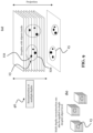
- FIG. 13 highlights that the apparatus 1200 performs in-line lens-free holographic imaging.
- the holographic imager 1201 of the apparatus 1200 comprises a light source 1201_a. With this light source 1201_a, the holographic imager 1201 is configured to illuminate the droplet 12 including the at least one object 12. For reasons of simplicity, again only one object 11 is shown in the droplet 12. Also, only one droplet 12 is shown, however, the apparatus 1200 works likewise with multiple objects 11 and/or multiple droplets 12.
- the light waves emitted by the light source io2i a may partly interact with the droplet 12, particularly with the object 11, and may partly go through the droplet 12 without interaction.
- holographic imaging performed by the apparatus 1200 is also lens-free.
- in-line lens-free holographic imaging captures holograms 13 without using lenses by recording interference patterns directly on the recording medium 1201_b, wherein a coherent light source 1201_a aligned with the droplet 12 and recording medium 1201_b may be used as an example (but not required).
- the processor 1202 of the apparatus 1200 is further able perform the reconstruction of the hologram 13 after or during artifact removal, for example, by reconstruction methods known in the art, so as to obtain the image 15.
- the present disclosure provides a solution for using in-line lens-free holographic imaging, to obtain high-quality images 15 of objects 11 in droplets 12, and to obtain characteristics 25 of the objects 11 based on the images 15.
Landscapes
- Engineering & Computer Science (AREA)
- Physics & Mathematics (AREA)
- General Physics & Mathematics (AREA)
- Theoretical Computer Science (AREA)
- Computing Systems (AREA)
- Multimedia (AREA)
- Health & Medical Sciences (AREA)
- General Health & Medical Sciences (AREA)
- Evolutionary Computation (AREA)
- Life Sciences & Earth Sciences (AREA)
- Software Systems (AREA)
- Chemical & Material Sciences (AREA)
- Artificial Intelligence (AREA)
- Molecular Biology (AREA)
- Dispersion Chemistry (AREA)
- Computational Linguistics (AREA)
- General Engineering & Computer Science (AREA)
- Mathematical Physics (AREA)
- Biophysics (AREA)
- Biomedical Technology (AREA)
- Data Mining & Analysis (AREA)
- Analytical Chemistry (AREA)
- Biochemistry (AREA)
- Immunology (AREA)
- Pathology (AREA)
- Computer Vision & Pattern Recognition (AREA)
- Databases & Information Systems (AREA)
- Medical Informatics (AREA)
- Holo Graphy (AREA)
Priority Applications (2)
| Application Number | Priority Date | Filing Date | Title |
|---|---|---|---|
| US18/882,206 US20250085665A1 (en) | 2023-09-13 | 2024-09-11 | Method for Imaging Objects Contained in a Droplet |
| US19/077,207 US20250208567A1 (en) | 2023-09-13 | 2025-03-12 | In-Line Lens-Free Holographic Imaging of Objects Contained in a Liquid Sample in a Microwell |
Applications Claiming Priority (1)
| Application Number | Priority Date | Filing Date | Title |
|---|---|---|---|
| EP23197046 | 2023-09-13 |
Publications (2)
| Publication Number | Publication Date |
|---|---|
| EP4524660A2 true EP4524660A2 (de) | 2025-03-19 |
| EP4524660A3 EP4524660A3 (de) | 2025-07-30 |
Family
ID=88021015
Family Applications (1)
| Application Number | Title | Priority Date | Filing Date |
|---|---|---|---|
| EP24194852.0A Pending EP4524660A3 (de) | 2023-09-13 | 2024-08-16 | Verfahren zur linsenfreien holographischen in-line-bildgebung von objekten in einem tröpfchen |
Country Status (2)
| Country | Link |
|---|---|
| US (1) | US20250085665A1 (de) |
| EP (1) | EP4524660A3 (de) |
-
2024
- 2024-08-16 EP EP24194852.0A patent/EP4524660A3/de active Pending
- 2024-09-11 US US18/882,206 patent/US20250085665A1/en active Pending
Non-Patent Citations (1)
| Title |
|---|
| LUOZHENXIANG ET AL.: "Fast compressive lens-free tomography for D biological cell culture imaging", OPTICS EXPRESS, vol. 28, no. 18, 2020, pages 26935 - 26952 |
Also Published As
| Publication number | Publication date |
|---|---|
| US20250085665A1 (en) | 2025-03-13 |
| EP4524660A3 (de) | 2025-07-30 |
Similar Documents
| Publication | Publication Date | Title |
|---|---|---|
| JP7346726B2 (ja) | 深層学習による位相画像の再構築 | |
| Manifold et al. | Denoising of stimulated Raman scattering microscopy images via deep learning | |
| Moon et al. | Automated three-dimensional identification and tracking of micro/nanobiological organisms by computational holographic microscopy | |
| Kervrann et al. | A guided tour of selected image processing and analysis methods for fluorescence and electron microscopy | |
| Tang et al. | RestoreNet-Plus: Image restoration via deep learning in optical synthetic aperture imaging system | |
| Wei et al. | Mesh defiltering via cascaded geometry recovery | |
| Han et al. | System-and sample-agnostic isotropic three-dimensional microscopy by weakly physics-informed, domain-shift-resistant axial deblurring | |
| Feng et al. | Untrained network regularized by total variation in single-shot lensless holography | |
| Yang et al. | Transfer learning in general lensless imaging through scattering media | |
| Barutcu et al. | Compressive ptychography using deep image and generative priors | |
| US20250085665A1 (en) | Method for Imaging Objects Contained in a Droplet | |
| Peng et al. | Leonardo: A toolset to remove sample-induced aberrations in light sheet microscopy images | |
| US20180365810A1 (en) | Object image recovery from digital holograms | |
| US20250208567A1 (en) | In-Line Lens-Free Holographic Imaging of Objects Contained in a Liquid Sample in a Microwell | |
| Gao et al. | High-Fidelity Holographic Reconstruction via Physics-Aware Heterogeneous Self-Supervised Learning | |
| Vinogradova et al. | Estimation of optical aberrations in 3D microscopic bioimages | |
| Moon et al. | AI-driven digital holographic microscopy for label-free quantitative cellular analysis: toward low-cost and field-deployable platforms | |
| Hou et al. | HD2Net: a deep learning framework for simultaneous denoising and deaberration in fluorescence microscopy | |
| Kwon et al. | Seeing Video Through Optical Scattering Media using Spatio-Temporal Diffusion Models | |
| Liang et al. | Improved Scattering Autocorrelation Imaging Method Based on Deep Learning Denoising | |
| Mayya K et al. | SiDIP-Deep Image Prior to Improve Siamese Network Performance on Noisy Images | |
| Rajput et al. | Physics-Informed Synthetic Dataset and Denoising TIE-Reconstructed Phase Maps in Transient Flows Using Deep Learning | |
| He et al. | Fluorescence-illuminated Diffraction Tomography using Explicit Neural Fields | |
| Zhao et al. | MLDiff: a VAE-integrated diffusion model with fourier filter for high quality line drawing generation of ancient murals | |
| Gao et al. | Scattering Imaging |
Legal Events
| Date | Code | Title | Description |
|---|---|---|---|
| PUAI | Public reference made under article 153(3) epc to a published international application that has entered the european phase |
Free format text: ORIGINAL CODE: 0009012 |
|
| STAA | Information on the status of an ep patent application or granted ep patent |
Free format text: STATUS: THE APPLICATION HAS BEEN PUBLISHED |
|
| REG | Reference to a national code |
Ref country code: DE Ref legal event code: R079 Free format text: PREVIOUS MAIN CLASS: G03H0001080000 Ipc: G03H0001040000 |
|
| AK | Designated contracting states |
Kind code of ref document: A2 Designated state(s): AL AT BE BG CH CY CZ DE DK EE ES FI FR GB GR HR HU IE IS IT LI LT LU LV MC ME MK MT NL NO PL PT RO RS SE SI SK SM TR |
|
| RIC1 | Information provided on ipc code assigned before grant |
Ipc: G06V 20/64 20220101ALN20250318BHEP Ipc: G06V 10/82 20220101ALN20250318BHEP Ipc: G06V 10/141 20220101ALN20250318BHEP Ipc: G06T 7/37 20170101ALN20250318BHEP Ipc: G06N 3/045 20230101ALN20250318BHEP Ipc: G01N 15/0227 20240101ALN20250318BHEP Ipc: G03H 1/00 20060101ALN20250318BHEP Ipc: G03H 1/26 20060101ALI20250318BHEP Ipc: G03H 1/08 20060101ALI20250318BHEP Ipc: G03H 1/04 20060101AFI20250318BHEP |
|
| PUAL | Search report despatched |
Free format text: ORIGINAL CODE: 0009013 |
|
| AK | Designated contracting states |
Kind code of ref document: A3 Designated state(s): AL AT BE BG CH CY CZ DE DK EE ES FI FR GB GR HR HU IE IS IT LI LT LU LV MC ME MK MT NL NO PL PT RO RS SE SI SK SM TR |
|
| RIC1 | Information provided on ipc code assigned before grant |
Ipc: G03H 1/04 20060101AFI20250623BHEP Ipc: G03H 1/08 20060101ALI20250623BHEP Ipc: G03H 1/26 20060101ALI20250623BHEP Ipc: G03H 1/00 20060101ALN20250623BHEP Ipc: G01N 15/0227 20240101ALN20250623BHEP Ipc: G06N 3/045 20230101ALN20250623BHEP Ipc: G06T 7/37 20170101ALN20250623BHEP Ipc: G06V 10/141 20220101ALN20250623BHEP Ipc: G06V 10/82 20220101ALN20250623BHEP Ipc: G06V 20/64 20220101ALN20250623BHEP |
|
| STAA | Information on the status of an ep patent application or granted ep patent |
Free format text: STATUS: REQUEST FOR EXAMINATION WAS MADE |
|
| 17P | Request for examination filed |
Effective date: 20260122 |