EP4524601A2 - Réseaux à commande de phase optique pour communications optiques et systèmes de détection et de télémétrie par la lumière - Google Patents
Réseaux à commande de phase optique pour communications optiques et systèmes de détection et de télémétrie par la lumière Download PDFInfo
- Publication number
- EP4524601A2 EP4524601A2 EP24195790.1A EP24195790A EP4524601A2 EP 4524601 A2 EP4524601 A2 EP 4524601A2 EP 24195790 A EP24195790 A EP 24195790A EP 4524601 A2 EP4524601 A2 EP 4524601A2
- Authority
- EP
- European Patent Office
- Prior art keywords
- lidar
- signal
- signals
- opa
- autonomous vehicle
- Prior art date
- Legal status (The legal status is an assumption and is not a legal conclusion. Google has not performed a legal analysis and makes no representation as to the accuracy of the status listed.)
- Pending
Links
Images





Classifications
-
- G—PHYSICS
- G01—MEASURING; TESTING
- G01S—RADIO DIRECTION-FINDING; RADIO NAVIGATION; DETERMINING DISTANCE OR VELOCITY BY USE OF RADIO WAVES; LOCATING OR PRESENCE-DETECTING BY USE OF THE REFLECTION OR RERADIATION OF RADIO WAVES; ANALOGOUS ARRANGEMENTS USING OTHER WAVES
- G01S7/00—Details of systems according to groups G01S13/00, G01S15/00, G01S17/00
- G01S7/003—Transmission of data between radar, sonar or lidar systems and remote stations
-
- G—PHYSICS
- G01—MEASURING; TESTING
- G01S—RADIO DIRECTION-FINDING; RADIO NAVIGATION; DETERMINING DISTANCE OR VELOCITY BY USE OF RADIO WAVES; LOCATING OR PRESENCE-DETECTING BY USE OF THE REFLECTION OR RERADIATION OF RADIO WAVES; ANALOGOUS ARRANGEMENTS USING OTHER WAVES
- G01S7/00—Details of systems according to groups G01S13/00, G01S15/00, G01S17/00
- G01S7/48—Details of systems according to groups G01S13/00, G01S15/00, G01S17/00 of systems according to group G01S17/00
- G01S7/481—Constructional features, e.g. arrangements of optical elements
- G01S7/4817—Constructional features, e.g. arrangements of optical elements relating to scanning
-
- G—PHYSICS
- G01—MEASURING; TESTING
- G01S—RADIO DIRECTION-FINDING; RADIO NAVIGATION; DETERMINING DISTANCE OR VELOCITY BY USE OF RADIO WAVES; LOCATING OR PRESENCE-DETECTING BY USE OF THE REFLECTION OR RERADIATION OF RADIO WAVES; ANALOGOUS ARRANGEMENTS USING OTHER WAVES
- G01S17/00—Systems using the reflection or reradiation of electromagnetic waves other than radio waves, e.g. lidar systems
- G01S17/88—Lidar systems specially adapted for specific applications
- G01S17/93—Lidar systems specially adapted for specific applications for anti-collision purposes
- G01S17/931—Lidar systems specially adapted for specific applications for anti-collision purposes of land vehicles
-
- G—PHYSICS
- G01—MEASURING; TESTING
- G01S—RADIO DIRECTION-FINDING; RADIO NAVIGATION; DETERMINING DISTANCE OR VELOCITY BY USE OF RADIO WAVES; LOCATING OR PRESENCE-DETECTING BY USE OF THE REFLECTION OR RERADIATION OF RADIO WAVES; ANALOGOUS ARRANGEMENTS USING OTHER WAVES
- G01S7/00—Details of systems according to groups G01S13/00, G01S15/00, G01S17/00
- G01S7/48—Details of systems according to groups G01S13/00, G01S15/00, G01S17/00 of systems according to group G01S17/00
- G01S7/481—Constructional features, e.g. arrangements of optical elements
- G01S7/4811—Constructional features, e.g. arrangements of optical elements common to transmitter and receiver
-
- G—PHYSICS
- G01—MEASURING; TESTING
- G01S—RADIO DIRECTION-FINDING; RADIO NAVIGATION; DETERMINING DISTANCE OR VELOCITY BY USE OF RADIO WAVES; LOCATING OR PRESENCE-DETECTING BY USE OF THE REFLECTION OR RERADIATION OF RADIO WAVES; ANALOGOUS ARRANGEMENTS USING OTHER WAVES
- G01S7/00—Details of systems according to groups G01S13/00, G01S15/00, G01S17/00
- G01S7/48—Details of systems according to groups G01S13/00, G01S15/00, G01S17/00 of systems according to group G01S17/00
- G01S7/481—Constructional features, e.g. arrangements of optical elements
- G01S7/4811—Constructional features, e.g. arrangements of optical elements common to transmitter and receiver
- G01S7/4813—Housing arrangements
-
- G—PHYSICS
- G01—MEASURING; TESTING
- G01S—RADIO DIRECTION-FINDING; RADIO NAVIGATION; DETERMINING DISTANCE OR VELOCITY BY USE OF RADIO WAVES; LOCATING OR PRESENCE-DETECTING BY USE OF THE REFLECTION OR RERADIATION OF RADIO WAVES; ANALOGOUS ARRANGEMENTS USING OTHER WAVES
- G01S7/00—Details of systems according to groups G01S13/00, G01S15/00, G01S17/00
- G01S7/48—Details of systems according to groups G01S13/00, G01S15/00, G01S17/00 of systems according to group G01S17/00
- G01S7/483—Details of pulse systems
- G01S7/484—Transmitters
-
- G—PHYSICS
- G02—OPTICS
- G02B—OPTICAL ELEMENTS, SYSTEMS OR APPARATUS
- G02B27/00—Optical systems or apparatus not provided for by any of the groups G02B1/00 - G02B26/00, G02B30/00
- G02B27/0087—Phased arrays
-
- H—ELECTRICITY
- H04—ELECTRIC COMMUNICATION TECHNIQUE
- H04B—TRANSMISSION
- H04B10/00—Transmission systems employing electromagnetic waves other than radio-waves, e.g. infrared, visible or ultraviolet light, or employing corpuscular radiation, e.g. quantum communication
- H04B10/11—Arrangements specific to free-space transmission, i.e. transmission through air or vacuum
- H04B10/112—Line-of-sight transmission over an extended range
Definitions
- Wireless optical communication enables high-throughput and long-range communication, in part due to high gain offered by the narrow angular width of the transmitted beam.
- the narrow beam also requires that it must be accurately and actively pointed in order to remain aligned to an aperture of a communications terminal at the remote end. This pointing may be accomplished by small mirrors (e.g., MEMS or voice-coil based fast-steering mirror mechanisms) that are actuated to steer the beam.
- electro-optic steering of beams with no moving parts is used to steer the beam, which provides cost, lifetime and performance advantages.
- Optical Phased Arrays are a critical technology component, with added benefits of adaptive-optics, point-to-multipoint support, and mesh network topologies. Each active element in the OPA requires electro-optic phase shifting capability.
- LIDAR Light detection and ranging
- MEMS micro-electro-mechanical systems
- the first device comprising an optical phased array (OPA) including a photonic integrated circuit (PIC) comprising a plurality of phase shifters arranged in a plurality of segments; one or more additional phase shifters, a plurality of switches corresponding to each of the plurality of segments; and a plurality of switches corresponding to each of the plurality of segments, the plurality of switches configured to be placed in one of i) a first position or ii) a second position, wherein the first position allows for joint functionality of the plurality of segments and wherein the second position allows for independent functionality of the plurality of segments; and a plurality of transceivers, each of the plurality of transceivers comprising a transceiver switch, wherein each a transceiver switch is configured to be placed in in one of i) a first position or ii) a second position, wherein the first position allows for a signal to be received by a LIDAR receiver of the plurality of transce
- OPA optical phased array
- the first device is an autonomous vehicle.
- the plurality of transceivers includes a full array transceiver and a plurality of segment transceivers.
- the plurality of transceivers each further includes a laser source configured to produce a signal, and a phase modulator operatively connected to the laser source and configured to encode signal information onto signals therefrom.
- the plurality of transceivers each further includes a local oscillator (LO) phase modulator for LIDAR configured to modulate received signals using light from the laser source, and a LO phase modulator for optical communications configured to modulate received signals using light from the laser source.
- LO local oscillator
- the plurality of transceivers each further includes wavelength and phase locking electronics operatively coupled to the LO phase modulator for LIDAR signals and the LO phase modulator for optical communications and configured to allow specific ranges of wavelengths or specific phases of photons of a signal to be received.
- the plurality of transceivers each further includes a LIDAR receiver configured to receive LIDAR signals when the transceiver switch is in the first position; and an optical communications receiver configured to receive optical communications signals when the transceiver switch is in the second position.
- the plurality of transceivers each further includes one or more semiconductor optical amplifiers configured to amplify a signal to be transmitted.
- the plurality of transceivers each further includes a circulator configured to route incoming and outgoing signals while keeping them on at least partially separate paths.
- the plurality of transceivers each include separate transmitter and receiver components.
- the transmitter components of the plurality of transceivers are contained on a first PIC and the receiver components of the plurality of transceivers are contained on a second PIC.
- Another aspect of the disclosure provides a method of detecting a plurality of objects in an environment of a first autonomous vehicle.
- the method comprising placing a plurality of switches of an optical phased array (OPA) architecture of the first autonomous vehicle into a first position wherein the first position allows for j oint functionality of a plurality of segments, wherein a plurality of phase shifters are arranged in the plurality of segments; transmitting, via a full array transmitter of the OPA architecture of the first autonomous vehicle, a first LIDAR signal, the first LIDAR signal spanning a field of view (FOV) of an OPA architecture of the first autonomous vehicle; receiving, via a full array receiver of the OPA architecture of the first autonomous vehicle, a first reflected LIDAR signal, the first reflected LIDAR signal being a reflection of the first LIDAR signal containing information regarding objects in the environment of the first autonomous vehicle; identifying, by one or more processors of the first autonomous vehicle, a plurality of areas of interest in the environment of the first autonomous vehicle
- the full array transmitter and receiver are a full array transceiver and the segment transmitters and segment receivers are segment transceivers.
- transmitting, via the full array transmitter of the OPA architecture of the first autonomous vehicle, the first LIDAR signal includes transmitting a plurality of first LIDAR signals; and receiving, via the full array receiver of the OPA architecture of the first autonomous vehicle, the first reflected LIDAR signal includes receiving a first reflected plurality of LIDAR signals.
- the method further includes dithering the first plurality of LIDAR signals.
- Another aspect of the disclosure provides a method of receiving information regarding an environment of a first vehicle.
- the method comprising detecting an object in an environment of a first autonomous vehicle, wherein the object is a remote autonomous vehicle, the remote autonomous vehicle is at least partially within a FOV of an OPA architecture of the first autonomous vehicle, and wherein the detecting occurs while one or more of a plurality of transceiver switches are in a first position, the first position allowing for a signal to be received by a LIDAR receiver; transmitting, via one of a plurality of transmitters of an OPA architecture of the first autonomous vehicle, an optical communications signal to the detected object; and receiving, via one of a plurality of receivers of the OPA architecture of the first autonomous vehicle, an optical communications signal from the detected object, wherein the optical communications signal from the detected object includes information regarding the environment of the first vehicle.
- the remote autonomous vehicle is at least partially occluding the FOV of the first autonomous vehicle.
- receiving, via one of the plurality of receivers of the OPA architecture of the first autonomous vehicle, the optical communications signal from the detected object occurs when one or more or more of the plurality of transceiver switches is in a second position, the second position allowing for a signal to be received by an optical communications receiver.
- transmitting, via one of the plurality of transmitters of an OPA architecture of the first autonomous vehicle, the optical communications signal to the detected object includes transmitting a plurality of optical communications signals to the detected object.
- the method further includes dithering the plurality of optical communications signals.
- the technology relates to an optical phased array (OPA) architecture for a device capable of transmitting and receiving both optical communications signals and light detection and ranging (LIDAR) signals.
- OPA optical phased array
- the OPA architecture may involve the use of a single OPA chip with a plurality of photonic integrated circuits (PIC).
- PIC photonic integrated circuits
- the transmitters and receivers (or transceivers) of the OPA architecture may include switches.
- the transceiver switch may enable changing between transmitting and receiving optical communications signals and LIDAR signals.
- transmitting (Tx) and receiving (Rx) both optical communications signals and LIDAR signals requires two separate architectures (e.g., an optical communications architecture and a LIDAR architecture). Having a system with two structures may require extra materials and may be more costly to maintain. Moreover, two structure systems may be slower in compensating for atmospheric aberrations. The slower compensation may lead to decreased coupling efficiencies, slower data rates, and decreased range.
- a first device may include an OPA architecture with transmitters and receivers (or transceivers) with switches to enable changing between transmitting and receiving optical communications signals and LIDAR signals.
- the first device may be a first autonomous vehicle.
- the OPA architecture of the first device may be a segmented OPA architecture containing a plurality of segments.
- Each of the plurality of segments may be configured to transmit and receiver both LIDAR and optical communications signals.
- each of these segments may be contained on the same or differing PICS include a PIC with a plurality of features including a micro-lens array, an emitter associated with each micro-lens, a set of phase shifters for each micro-lens, an emitter for each micro-lens, and waveguides (e.g., optical fibers) that connect the components in the OPA architecture.
- a plurality of splitters, phase shifters, and may be used to control whether the plurality of segments function independently or in conjunction with one another.
- the first device may include a radio frequency (RF) communications system configured to communicate with one or more remote devices. Additionally, the first device may include a plurality of segmented OPA architectures. The plurality of segmented OPA architectures may have differing fields of view (FOV). The differing fields of view of the plurality of OPA architectures may or may not overlap partially or not at all.
- Each of the plurality of segments is connected via waveguides (e.g., optical fibers) to a switch.
- the segmented OPA includes a switch for each segment of the plurality of segments.
- the plurality of switches may be configured to be in a first or second position.
- the first position may allow for Tx/Rx joint functionality with other segments of the segmented OPA architecture, whereas the second position may allow for Tx/Rx functionality independent of other segments of the segmented OPA architecture.
- the system may contain a plurality of transceivers.
- One of the plurality of transceivers may be a full array transceiver configured to allow for Tx/Rx functionality with all segments of the plurality of segments, whereas the remaining transceivers may be segment transceivers configured to allow for Tx/Rx functionality with a single segment of the plurality of segments.
- the plurality of transceivers may include a plurality of segment transceivers, each connected to one of the plurality of switches via waveguides (e.g., optical fibers).
- the plurality of segment transceivers may transmit and receive signals from corresponding segments of the plurality of segments when the corresponding switch is in the second position.
- the full array transceiver may be used to transmit and receive signal from the plurality of segments when the plurality of switches are in the first position.
- the transceiver structure may include a laser source, a phase modulator, a local oscillator (LO) phase modulator for LIDAR signals, a LO phase modulator for optical communications, a circulator, a transceiver switch, a LIDAR receiver, and an optical communications receiver.
- LO local oscillator
- the transceiver switch may be configured to be in a first position and a second position.
- the first position may allow for a signal to be received by the LIDAR receiver.
- the second position may allow for a signal to be received by the optical communications receiver.
- the switch may be changed from the first position to the second position by one or more processors of the first device based on the type of signal received.
- a LIDAR signal may be in a first range of wavelengths and or phases
- an optical communications signal may be in a second range of wavelengths and or phases.
- the one or more processors may change the transceiver switch to the first position.
- the one or more processors may change the transceiver switch to the second position.
- a first device may include separate OPAs for transmission and receipt of signals.
- the first device may include a transmit OPA and a receive OPA.
- the transceivers may include separate transmitter and receiver components or a first chip with transmitter components and a second chip with receiver components.
- the receive OPA may be operatively coupled to receiver components and the transmit OPA may be operatively coupled to the transmitter components.
- the transceiver structure may similarly include a laser source, a phase modulator, a local oscillator (LO) phase modulator for LIDAR signals, a LO phase modulator for optical communications, a switch, a LIDAR receiver, and an optical communications receiver.
- the switch may be configured to be in a first position and a second position. The first position may allow for a signal to be received by the LIDAR receiver. The second position may allow for a signal to be received by the optical communications receiver.
- the switch may be changed from the first position to the second position by one or more processors of the first device based on the type of signal received.
- a LIDAR signal may be in a first range of wavelengths and or phases, while an optical communications signal may be in a second range of wavelengths and or phases.
- the one or more processors may change the switch to the first position.
- the one or more processors may change the switch to the second position.
- the first device may be a first autonomous vehicle.
- the OPA architecture of the first autonomous vehicle may be configured to transmit and receive one or more LIDAR signals. Such signals may be used to detect objects in an environment surrounding the first autonomous vehicle. Additionally, the OPA architecture of the first autonomous vehicle may be configured to transmit and receive one or more optical communications signals to one or more remote autonomous vehicles in the environment surrounding the first autonomous vehicle.
- the OPA architecture may be used in a method of detecting a plurality of objects in an environment of a first autonomous vehicle.
- the OPA architecture may be used in a method of receiving information regarding an environment of a first vehicle. In some instances, the information may pertain to an area of the environment occluded by an object.
- the features and methodology described herein may provide a first device able to transmit and receive both optical communications signals and LIDAR signals using the same components.
- a device allows for both communications functionality (e.g., transmission and receipt of optical communications signals) as well as LIDAR functionality (e.g. transmission of LIDAR signals and receipt of reflected LIDAR signals) with lesser components, materials, and overall cost.
- devices such as the first device require less materials to construct and are easier to maintain overall.
- the first device may also have additional benefits from simultaneous multi-node, multi-code and multi-wavelength capability.
- the OPA aperture can be dynamically reconfigured from a single to multiple sub-apertures each with tailorable and optimizable LIDAR and/or communications functionality.
- multiple communication targets e.g., remote device or client device
- LIDAR targets e.g., objects in the FOV of the first device
- FIGURE 1A is a block diagram 100a of a first device 102 configured to form one or more links with a second device.
- the first and second devices may be part of a larger system.
- the system may include a plurality of autonomous vehicles configured to communicate with one another.
- the first and/or second device may be an autonomous vehicle.
- the system may be a free space optical communication (FSOC) system.
- the first and second devices may additionally be configured to transmit one or more LIDAR signals directed at the environment surrounding the first device and receive reflections of such signals from surfaces in the environment.
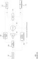
- FIGURE 1B is a block diagram 100b of the first device 102
- FIGURE 2 is a pictorial diagram 200 of an example device, such as the first device 102 of FIGURES 1A-1B
- a first device 102 includes one or more processors 104, a memory 106, a transceiver photonic integrated chip 112, and an optical phased array (OPA) architecture 114.
- the transceiver PIC 112 may be configured to transmit and receive signals via a bidirectional OPA.
- the transceiver chip 112 may be configured to transmit signals via a transmitter OPA and to receive signals via a receiver OPA.
- the transceiver chip 112 may include separate transmitter and receiver components or a first chip with transmitter components and a second chip with receiver components.
- the first device 102 may include more than one transceiver chip and/or more than one OPA architecture (e.g., more than one OPA chip).
- the one or more processors 104 may be any conventional processors, such as commercially available CPUs. Alternatively, the one or more processors may be a dedicated device such as an application specific integrated circuit (ASIC) or another hardware-based processor, such as a field programmable gate array (FPGA).
- FIGURES 1A-1B functionally illustrates the one or more processors 104 and memory 106 as being within the same block, such as in a modem 202 for digital signal processing shown in FIGURE 2
- the one or more processors 104 and memory 106 may actually comprise multiple processors and memories that may or may not be stored within the same physical housing, such as in both the modem 202 and a separate processing unit 203. Accordingly, references to a processor or computer will be understood to include references to a collection of processors or computers or memories that may or may not operate in parallel.
- Memory 106 may store information accessible by the one or more processors 104, including data 108, and instructions 110, that may be executed by the one or more processors 104.
- the memory may be of any type capable of storing information accessible by the processor, including a computer-readable medium such as a hard-drive, memory card, ROM, RAM, DVD or other optical disks, as well as other write-capable and read-only memories.
- the system and method may include different combinations of the foregoing, whereby different portions of the data 108 and instructions 110 are stored on different types of media.
- calibration information such as one or more offsets determined for tracking a signal, may be stored.
- Data 108 may be retrieved, stored or modified by one or more processors 104 in accordance with the instructions 110.
- the data 108 may be stored in computer registers, in a relational database as a table having a plurality of different fields and records, XML documents or flat files.
- the data 108 may also be formatted in any computer-readable format such as, but not limited to, binary values or Unicode.
- image data may be stored as bitmaps including grids of pixels that are stored in accordance with formats that are compressed or uncompressed, lossless (e.g., BMP) or lossy (e.g., JPEG), and bitmap or vector- based (e.g., SVG), as well as computer instructions for drawing graphics.
- the data 108 may comprise any information sufficient to identify the relevant information, such as numbers, descriptive text, proprietary codes, references to data stored in other areas of the same memory or different memories (including other network locations) or information that is used by a function to calculate the relevant data.
- the instructions 110 may be any set of instructions to be executed directly (such as machine code) or indirectly (such as scripts) by the one or more processors 104.
- the instructions 110 may be stored as computer code on the computer-readable medium.
- the terms "instructions” and “programs” may be used interchangeably herein.
- the instructions 110 may be stored in object code format for direct processing by the one or more processors 104, or in any other computer language including scripts or collections of independent source code modules that are interpreted on demand or compiled in advance. Functions, methods and routines of the instructions 110 are explained in more detail below.
- the one or more processors 104 may be in communication with the transceiver chip 112. As shown in FIGURE 2 , the one or more processors in the modem 202 may be in communication with the transceiver chip 112, being configured to receive and process incoming optical signals and to transmit optical signals.
- the transceiver chip 112 may include one or more transmitter components and one or more receiver components.
- the one or more processors 104 may therefore be configured to transmit, via the transmitter components, data in a signal, and also may be configured to receive, via the receiver components, communications and/or data in a signal. The received signal may be processed by the one or more processors 104 to extract the communications and/or data.
- the transmitter components may include at minimum a light source, such as laser source 116.
- Other transmitter components may include an amplifier, such as a high-power semiconductor optical amplifier 204. In some implementations, the amplifier is on a separate photonics chip.
- the light output of the laser source 116, or optical signal may be controlled by a current, or electrical signal, applied directly to the laser source, such as from a modulator that modulates a received electrical signal. Light transmitted from the laser source 116 is received by the OPA architecture 114.
- the receiver components may include at minimum a sensor 118, such as a photodiode.
- the sensor may convert a received signal (e.g., a LIDAR or optical communications signal), into an electrical signal that can be processed by the one or more processors.
- Other receiver components may include an attenuator, such as a variable optical attenuator 206, an amplifier, such as a semiconductor optical amplifier 208, or a filter.
- the one or more processors 104 may be in communication with the OPA architecture 114.
- the OPA architecture 114 may include a micro-lens array, an emitter associated with each micro-lens in the array, a plurality of phase shifters, and waveguides that connect the components in the OPA.
- the OPA architecture may be positioned on a single chip, an OPA chip.
- the waveguides progressively merge between a plurality of emitters and an edge coupler that connect to other transmitter and/or receiver components.
- the waveguides may direct light between photodetectors or fiber outside of the OPA architecture, the phase shifters, the waveguide combiners, the emitters and any additional component within the OPA.
- the waveguide configuration may combine two waveguides at each stage, which means the number of waveguides is reduced by a factor of two at every successive stage closer to the edge coupler.
- the point of combination may be a node, and a combiner may be at each node.
- the combiner may be a 2x2 multimode interference (MMI) or directional coupler.
- MMI multimode interference
- the first device 102 may include additional components to support functions of the device.
- the first device may include one or more lenses and/or mirrors that form a telescope.
- the telescope may receive collimated light and output collimated light.
- the telescope may include an objective portion, an eyepiece portion, and a relay portion.
- the first device may include a telescope including an objective lens 210, an eyepiece lens 212, and an aperture 214 (or opening) through which light may enter and exit the device.
- the aperture 214 is depicted as distinct from the objective lens 210, though the objective lens 210 may be positioned within the aperture.
- the first device may include a circulator or wavelength splitter, such as a single mode circulator 218, that routes incoming and outgoing signals or light while keeping them on at least partially separate paths.
- the first optical communications terminal may include one or more sensors 220 for detecting measurements of environmental features and/or system components.
- the first device 102 may include one or more steering mechanisms, such as one or more bias means for controlling one or more phase shifters, which may be part of the OPA architecture 114, and/or an actuated/steering mirror (not shown), such as a fast/fine pointing mirror.
- the actuated mirror may be a MEMS 2-axis mirror, 2-axis voice coil mirror, or a piezoelectric 2-axis mirror.
- the one or more processors 104 such as those in the processing unit 203, may be configured to receive and process signals from the one or more sensors 220, the transceiver chip 112, and/or the OPA architecture 114 and to control the one or more steering mechanisms to adjust a pointing direction and/or wavefront shape.
- the first device terminal also includes optical fibers or waveguides connecting optical components, creating a path between the laser source 116 and OPA architecture 114 and a path between the OPA architecture 114 and the sensor 118.
- the second device 122 may output the Tx signals as an optical communications signal 20b (e.g., light) pointed towards the first device 102, which receives the optical communications signal 20b (e.g., light) as corresponding Rx signals.
- the second device 122 may be configured the same or similarly to the first device 102.
- the second device 122 may be configured to transmit and receive LIDAR signals directed at the environment surrounding the second device 122 in the same manner as device 102.
- the second device 122 includes one or more processors, 124, a memory 126, a transceiver chip 132, and an OPA architecture 134.
- the one or more processors 124 may be similar to the one or more processors 104 described above.
- a communication link 22 may be formed between the first device 102 and the second device 122 when the transceivers of the first and second devices are aligned.
- the alignment can be determined using the optical communications signals 20a, 20b to determine when line-of-sight is established between the devices 102, 122.
- the one or more processors 104 can send communication signals using the optical communications signal 20a to the second device 122 through free space, and the one or more processors 124 can send communication signals using the optical communications signal 20b to the first device 102 through free space.
- the communication link 22 between the first and second devices 102, 122 allows for the bi-directional transmission of data between the two devices.
- the communication link 22 in these examples may be free-space optical communications (FSOC) links.
- one or more of the communication links 22 may be radio-frequency communication links or other type of communication link capable of traveling through free space.
- Memory 126 may store information accessible by the one or more processors 124, including data 128 and instructions 130 that may be executed by processor 124. Memory 126, data 128, and instructions 130 may be configured similarly to memory 106, data 108, and instructions 110 described above.
- the transceiver chip 132 and the OPA architecture 134 of the second device 122 may be similar to the transceiver chip 112 and the OPA architecture 114.
- the transceiver chip 132 may include both transmitter components and receiver components.
- the transmitter components may include a light source, such as laser source 136 configured similar to the laser source 116.
- Other transmitter components may include an amplifier, such as a high-power semiconductor optical amplifier.
- the receiver components may include a sensor 138 configured similar to sensor 118.
- receiver components may include an attenuator, such as a variable optical attenuator, an amplifier, such as a semiconductor optical amplifier, or a filter.
- the OPA architecture 134 may include an OPA chip including a micro-lens array, a plurality of emitters, a plurality of phase shifters. Additional components for supporting functions of the second device 122 may be included similar to the additional components described above.
- the second device 122 may have a system architecture that is same or similar to the system architecture shown in FIGURE 2 .
- the first device 102 is configured to transmit a LIDAR signal 20c into an environment thereof.
- the LIDAR signal 20c may span an entire field of view (FOV) 142 of the first device or a portion thereof.
- the LIDAR signal 20c signal may contact an object 140 or a plurality of objects in the environment. The contact may result in a reflected LIDAR signal 20d that may be received by the device 102.
- FOV field of view
- the received signal may be an optical communication signal received from a remote device or client device, such as optical communications signal 20b of FIGURE 1A or a reflected LIDAR signal, such as reflected LIDAR signal 20d of FIGURE 1B .
- the second device 122 may also include and be capable of such features.
- the second device 122 may include one or both of the transceiver structures of FIGURES 3A-3B and be figured to transmit and receive signals as discussed with respect to FIGURES 3A-3B .
- FIGURE 3A illustrates a transceiver structure 300a in which the transceiver is configured to transmit and receive signals via a bidirectional OPA.
- the transceiver structure 300a includes a laser source 302, a phase modulator 304, a local oscillator (LO) phase modulator for LIDAR 306, a LO phase modulator for optical communications 308, a circulator 318, a transceiver switch 310, a LIDAR receiver 312, an optical communications receiver 314, and a semiconductor optical amplifier (SOA) 316.
- the components of the transceiver structure 300a may be connected by one or more waveguides (e.g., optical fibers).
- the laser source 302 may generate a signal (e.g., light).
- the laser source 302 may be a distributed feedback laser (DFB), a laser diode, a fiber laser, a solid-state laser, an extended cavity diode laser (ECL), or a seed laser.
- the light output of the laser source 302, or signal may be controlled by a current, or electrical signal, applied directly to the laser source 302, such as from a modulator that modulates a received electrical signal.
- the generated signal may be directed from the laser source 302 to a phase modulator 304.
- the phase modulator 304 may be configured to encode the signal information (e.g., information for an optical communications signal, LIDAR waveform, etc.) onto the signal to be transmitted.
- the signal information e.g., information for an optical communications signal, LIDAR waveform, etc.
- phase codes may additionally be encoded into the signals to be transmitted.
- the phase codes may allow for reduced interference between differing transceivers.
- the encoded information determines the signal type to be transmitted.
- an optical communications signal may be modulated via one or more modulation techniques such as phase-shift-keying (PSK) (e.g., Binary Phase-Shift Keying (BPSK), Quadrature Phase Shift Keying (QPSK), etc.).
- PSK phase-shift-keying
- BPSK Binary Phase-Shift Keying
- QPSK Quadrature Phase Shift Keying
- BPSK Binary Phase-Shift Keying
- QPSK Quadrature Phase Shift Keying
- BPSK Binary Phase-Shift Keying
- QPSK Quadrature Phase Shift Keying
- a LIDAR signal may be a square pulse format phase modulated waveform.
- the phase of the square pulse may be modulated by specific increments. In some instances, the specific increment may be ⁇ .
- a pulse width of the LIDAR signal may be determined by an expected distance from the first device to an object. In some instances, the pulse width of the LIDAR signal may be varied over time. In this regard, the pulse width may be varied starting at a longer pulse width with subsequently a shorter pulse width. The longer pulse width may allow the first device to determine a relative location of an object within the FOV thereof.
- the shorter pulse width may allow for higher resolution of the object at the relative location.
- the first device may conduct a LIDAR scan across the FOV thereof at a first pulse width.
- the pulse width may be varied (e.g., from longer pulse widths to shorter pulse widths) at positions where an object is detected.
- a repetition rate of the LIDAR signal may be dependent on one or more performance metrics of the first device such as an update rate or refresh rate, point to point scan time, number of points in a point cloud image to be generated, etc.
- the generated signal may be directed from the phase modulator 304 to the SOA 316.
- the SOA 316 may be used by the phase modulator 304 to increase or boost a power level of a signal (e.g., amplify). This may, for example, extend range, data rate capabilities or area coverage rates of the generated signal.
- the SOA may be heterogeneously integrated onto the PIC or grown directly onto the PIC (e.g., silicon PIC) with a III-V pad and quantum dash structures which may minimize negative effects due to lattice mismatches and dislocations in the growth structure.
- the optical power when an optical communications signal is transmitted, the optical power can be amplified such that the power of the beam remains within eye-safe limits as well as controlled with a feedback loop to avoid saturation effects in the receiver OPA of a remote device.
- the SOA 316 may be a cascaded series of SOAs.
- the generated signal may be directed from the SOA 316 to the circulator 318.
- the circulator 318 or wavelength splitter, such as a single mode circulator may be configured to route incoming and outgoing signals (e.g., light) while keeping them on at least partially separate paths.
- circulator 318 may isolate forward and backward propagating signals such that transmitted signals may be routed to the OPA for transmission and received signals may be routed to the receiver components for receipt.
- the circulator 318 may connect to and route a signal from the transceiver structure 300a to the OPA of the first device 102 for transmission.
- a received signal may be routed from the OPA of the first device 102 to the circulator 318.
- the circulator 318 may be configured to route incoming and outgoing signals (e.g., light) while keeping them on at least partially separate paths and may isolate forward and backward propagating signals such that transmitted signals may be routed to the OPA for transmission and received signals may be routed to the receiver components for receipt.
- the circulator 318 may route a signal to the transceiver switch 310.
- the transceiver switch 310 may be configured to be in a first position and a second position.
- the first position may allow for a received signal that is a reflected LIDAR signal to be routed to and received by the LIDAR receiver 312.
- the second position may allow for a signal that is a received optical communications signal to be routed to and received by the optical communications receiver 314.
- the transceiver switch 310 may be changed from the first position to the second position by one or more processors of the first device 102 based on the type of signal received. For example, a reflected LIDAR signal may be in a first range of wavelengths and or phases, while a received optical communications signal may be in a second range of wavelengths and or phases.
- the one or more processors may change the transceiver switch 310 to the first position.
- the one or more processors may change the transceiver switch 310 to the second position.
- a reflected LIDAR signal received at the LIDAR receiver 312 from the transceiver switch 310 may be combined or mixed with a signal from the LO phase modulator for LIDAR 306.
- the LO phase modulator for LIDAR 306 may allow for coherent receiver functionality.
- the LO phase modulator for LIDAR 306 may allow specific ranges of wavelengths and/or phases of photons to be received at the LIDAR receiver 312.
- the LO phase modulator for LIDAR 306 may include a digital signal processor (DSP) to filter and/or compress received signals.
- DSP digital signal processor
- the LO phase modulator for LIDAR 306 may be configured to allow for phases of photons corresponding to LIDAR signals to be received at the LIDAR receiver 312.
- the LO phase modulator for LIDAR 306 may modulate received or reflected LIDAR signals by mixing a received signal with light from the laser source 302.
- the light to be mixed with the reflected LIDAR signal may first be modulated by the phase modulator 304 to encode information (e.g., range and velocity information) prior to passing through the LO phase modulator for LIDAR 306.
- signals from the LO phase modulator for LIDAR 306 may be amplified in a transimpedance amplifier (TIA) of the LIDAR receiver 312.
- TIA transimpedance amplifier
- the amplification may convert current to a voltage signal that is digitized by an Analog to Digital Converter (ADC) and further processed by the one or more processors 104 of the first device 102 (e.g., Field Programmable Gate Arrays (FPGA) and Central Processing Unit (CPU)).
- ADC Analog to Digital Converter
- processors 104 of the first device 102 e.g., Field Programmable Gate Arrays (FPGA) and Central Processing Unit (CPU)
- the FPGA may generate Point Cloud data (e.g., x spatial location, y spatial location, z range, v velocity vector) for each angular position.
- the Point Cloud data may be processed by the CPU.
- an optical communications signal received at the optical communications receiver 314 from the transceiver switch 310 may be combined or mixed with a signal from the LO phase modulator for optical communications 308.
- the LO phase modulator for optical communications 308 may be configured to allow phases of photons and/or wavelengths corresponding to optical communications signals to be received at the optical communications receiver 314. Signals from the LO phase modulator for optical communications 308 may be mixed with a received optical communications signal at the optical communications receiver 314.
- the received optical communications signal current may be amplified by a transimpedance amplifier (TIA) of the optical communications receiver 314.
- TIA transimpedance amplifier
- the amplification may convert current to a voltage signal that is digitized by an Analog to Digital Converter (ADC) and further processed by the one or more processors 104 of the first device 102 (e.g., FPGA and Central Processing Unit CPU).
- ADC Analog to Digital Converter
- the FPGA may, for example, apply Forward Error Corrections (FEC) algorithms that can reduce Bit Error Rates (BER).
- FEC Forward Error Corrections
- the optical communications receiver 314 and the LIDAR receiver 312 may each include at minimum a sensor, such as a photodiode.
- the sensor may convert a received signal into an electrical signal that can be processed by the one or more processors as discussed above.
- Other receiver components may include an attenuator, such as a variable optical attenuator, an amplifier, such as a semiconductor optical amplifier or a TIA, a filter, and/or phase locking electronics as discussed above.
- the transceiver structure 300a may additionally include optical wavelength and phase locking electronics.
- the wavelength and phase locking electronics may be operatively coupled to the laser source 302, the LO phase modulator for LIDAR 306, the LO phase modulator for optical communications 308, the LIDAR receiver 312, and the optical communications receiver 314.
- the wavelength and phase locking electronics may lock the LO phase modulator for LIDAR 306 to one or more specific phases of photons of a signal to be received.
- wavelength locking may not be required in the receipt of LIDAR signals since the transit and receive photons are from the same original source (e.g., the OPA of the first device 102).
- the wavelength and phase locking electronics may lock the LO phase modulator for optical communications 308 to one or more specific wavelengths and/or phases corresponding to optical communications signals to be received.
- wavelength locking may be used in the receipt of optical communications signals since the received signals are from the different sources (e.g., the OPA of the second device 122).
- the wavelength can be locked to a specific wavelength for coherent homodyne receiver applications or can be slightly offset for coherent heterodyne receiver applications.
- FIGURE 3B illustrates a transceiver structure 300b in which the transceiver may be configured to transmit signals via a transmitter OPA and receive signals via a receiver OPA.
- the transceiver chip 112 may include separate transmitter and receiver components or a first chip with transmitter components and a second chip with receiver components.
- the transceiver structure 300b may similarly include the laser source 302, the phase modulator 304, the local oscillator (LO) phase modulator for LIDAR 306, a LO phase modulator for optical communications 308, the transceiver switch 310, the LIDAR receiver 312, the optical communications receiver 314, and the SOA 316.
- LO local oscillator
- the SOA 316 may be connected with the transmitter OPA and the transceiver switch 310 may be connected with the receiver OPA.
- the components of the transceiver structure 300b may be connected by one or more waveguides (e.g., optical fibers).
- the laser source 302 may generate a signal (e.g., light).
- the laser source 302 may be a distributed feedback laser (DFB), a laser diode, a fiber laser, a solid-state laser, an extended cavity diode laser (ECL), or a seed laser.
- the light output of the laser source 302, or signal may be controlled by a current, or electrical signal, applied directly to the laser source 302, such as from a modulator that modulates a received electrical signal.
- the generated signal may be directed from the laser source 302 to a phase modulator 304.
- the phase modulator 304 may be configured to encode the signal information (e.g., information for an optical communications signal, LIDAR waveform, etc.) onto the signal to be transmitted as discussed above.
- phase codes may additionally be encoded into the signals to be transmitted. The phase codes may allow for reduced interference between differing transceivers.
- the generated signal may be directed from the phase modulator 304 to the SOA 316.
- the SOA 316 may be used by the phase modulator 304 to increase or boost a power level of a signal (e.g., amplify). This may, for example, extend range, data rate capabilities or area coverage rates of the signal.
- the SOA may be heterogeneously integrated onto the PIC or grown directly onto the PIC (e.g., silicon PIC) with a III-V pad and quantum dash structures which may minimize negative effects due to lattice mismatches and dislocations in the growth structure.
- the optical power when an optical communications signal is transmitted, the optical power can be amplified such that the power of the beam remains within eye-safe limits as well as controlled with a feedback loop to avoid saturation effects in the receiver OPA of a remote device.
- the SOA 316 may be a cascaded series of SOAs. The SOA 316 may connect to and route a signal from the transceiver structure 300b to the OPA of the first device 102 for transmission.
- a signal may be routed from the OPA of the first device 102 to transceiver switch 310.
- the transceiver switch 310 may be configured in the manner as discussed above.
- a reflected LIDAR signal received at the LIDAR receiver 312 from the transceiver switch 310 may be combined or mixed with a signal from the LO phase modulator for LIDAR 306.
- the LO phase modulator for LIDAR 306 may allow for coherent receiver functionality.
- the LO phase modulator for LIDAR 306 may allow specific ranges of wavelengths and/or phases of photons to be received at the LIDAR receiver 312.
- the LO phase modulator for LIDAR 306 may include a digital signal processor (DSP) to filter and/or compress received signals.
- DSP digital signal processor
- the LO phase modulator for LIDAR 306 may be configured to allow for phases of photons corresponding to LIDAR signals to be received at the LIDAR receiver 312.
- the LO phase modulator for LIDAR 306 may modulate received or reflected LIDAR signals by mixing a received signal with light from the laser source 302.
- the light to be mixed with the reflected LIDAR signal may first be modulated by the phase modulator 304 to encode information (e.g., range and velocity information) prior to passing through the LO phase modulator for LIDAR 306.
- signals from the LO phase modulator for LIDAR 306 may be amplified in a transimpedance amplifier (TIA) of the LIDAR receiver 312.
- TIA transimpedance amplifier
- the amplification may convert current to a voltage signal that is digitized by an Analog to Digital Converter (ADC) and further processed by the one or more processors 104 of the first device 102 (e.g., Field Programmable Gate Arrays (FPGA) and Central Processing Unit (CPU)).
- ADC Analog to Digital Converter
- processors 104 of the first device 102 e.g., Field Programmable Gate Arrays (FPGA) and Central Processing Unit (CPU)
- the FPGA may generate Point Cloud data (e.g., x spatial location, y spatial location, z range, v velocity vector) for each angular position.
- the Point Cloud data may be processed by the CPU.
- an optical communications signal received at the optical communications receiver 314 from the transceiver switch 310 may be combined or mixed with a signal from the LO phase modulator for optical communications 308.
- the LO phase modulator for optical communications 308 may be configured to allow phases of photons and/or wavelengths corresponding to optical communications signals to be received at the optical communications receiver 314. Signals from the LO phase modulator for optical communications 308 may be mixed with a received optical communications signal at the optical communications receiver 314.
- the received optical communications signal current may be amplified by a transimpedance amplifier (TIA) of the optical communications receiver 314.
- TIA transimpedance amplifier
- the amplification may convert current to a voltage signal that is digitized by an Analog to Digital Converter (ADC) and further processed by the one or more processors 104 of the first device 102 (e.g., FPGA and Central Processing Unit CPU).
- ADC Analog to Digital Converter
- the FPGA may, for example, apply Forward Error Corrections (FEC) algorithms that can reduce Bit Error Rates (BER).
- FEC Forward Error Corrections
- the optical communications receiver 314 and the LIDAR receiver 312 may include at minimum a sensor, such as a photodiode.
- the sensor may convert a received signal into an electrical signal that can be processed by the one or more processors as discussed above.
- Other receiver components may include an attenuator, such as a variable optical attenuator, an amplifier, such as a semiconductor optical amplifier or a TIA, a filter, and/or phase locking electronics as discussed above.
- the transceiver structure 300b may additionally include optical wavelength and phase locking electronics.
- the wavelength and phase locking electronics may be operatively coupled to the laser source 302, the LO phase modulator for LIDAR 306, the LO phase modulator for optical communications 308, the LIDAR receiver 312, and the optical communications receiver 314.
- the wavelength and phase locking electronics may be configured in the same manner as discussed above.
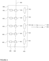
- FIGURE 4 represents features of OPA architecture 114 represented as an example OPA chip 400 including representations of a micro-lens array 410, a plurality of emitters 420, and a plurality of phase shifters 430. For clarity and ease of understanding, additional waveguides and other features are not depicted. Arrows 440, 442 represent the general direction of Tx signals (e.g., transmitted optical communications signal, LIDAR, etc.) and Rx signals (e.g., received optical communications signal, reflected LIDAR, etc.) as such signals pass or travel through the OPA chip 400.
- Tx signals e.g., transmitted optical communications signal, LIDAR, etc.
- Rx signals e.g., received optical communications signal, reflected LIDAR, etc.
- the micro-lens array 410 may include a plurality of convex micro-lenses 411-415 that focus the Rx signals onto respective ones of the plurality emitters positioned at the focal points of the micro-lens array.
- the dashed-line 450 represents the focal plane of the micro-lenses 411-415 of the micro-lens array 410.
- the micro-lens array 410 may be arranged in a grid pattern with a consistent pitch, or distance, between adjacent lenses. In other examples, the micro-lens array 410 may be in different arrangements having different numbers of rows and columns, different shapes, and/or different pitch (consistent or inconsistent) for different lenses.
- Each micro-lens of the micro-lens array may be 10's to 1000's of micrometers in diameter and height.
- each micro-lens of the micro-lens array may be manufactured by molding, printing, or etching a lens directly into a wafer of the OPA chip 400.
- the micro-lens array 410 may be molded, printed, or etched as a separately fabricated micro- lens array.
- the micro-lens array 410 may be a rectangular or square plate of glass or silica a few mm (e.g., 10 mm or more or less) in length and width and 0.2 mm or more or less thick.
- Integrating the micro-lens array within the OPA chip 400 may allow for the reduction of the grating emitter size and an increase in the space between emitters. In this way, two-dimensional waveguide routing in the OPA architecture may better fit in a single layer optical phased array. In other instances, rather than a physical micro-lens array, the function of the micro-lens array may be replicated using an array of diffractive optical elements (DOE).
- DOE diffractive optical elements
- Each micro-lens of the micro-lens array may be associated with a respective emitter of the plurality of emitters 420.
- each micro-lens may have an emitter from which Tx signals are received and to which the Rx signals are focused.
- micro-lens 411 is associated with emitter 421.
- each micro-lens 412-415 also has a respective emitter 422-425.
- the micro-lens focal length may be optimized for best transmit and receive coupling to the underlying emitters. This arrangement may thus increase the effective fill factor of the Rx signals at the respective emitter, while also expanding the Tx signals received at the micro-lenses from the respective emitter before the Tx signals leave the OPA chip 400.
- the plurality of emitters 420 may be configured to convert emissions from waveguides to free space and vice versa.
- the emitters may also generate a specific phase and intensity profile to further increase the effective fill factor of the Rx signals and improve the wavefront of the Tx signals.
- the phase and intensity profile may be determined using inverse design or other techniques in a manner that accounts for how transmitted signals will change as they propagate to and through the micro-lens array.
- the phase profile may be different from the flat profile of traditional grating emitters, and the intensity profile may be different from the gaussian intensity profile of traditional grating emitters.
- the emitters may be Gaussian field profile grating emitters.
- the phase shifters 430 may allow for sensing and measuring Rx signals and the altering of Tx signals to improve signal strength optimally combining an input wavefront into a single waveguide or fiber.
- Each emitter may be associated with a phase shifter. As shown in FIGURE 4 , each emitter may be connected to a respective phase shifter. As an example, the emitter 420 is associated with a phase shifter 430.
- the Rx signals received at the phase shifters 431-435 may be provided to receiver components including the sensor 118, and the Tx signals from the phase shifters 431-435 may be provided to the respective emitters of the plurality of emitter 420.
- the architecture for the plurality of phase shifters 430 may include at least one layer of phase shifters having at least one phase shifter connected to an emitter of the plurality of emitters 420.
- the phase shifter architecture may include a plurality of layers of phase shifters, where phase shifters in a first layer may be connected in series with one or more phase shifters in a second layer.
- the OPA architecture 114 of the first device 102 may be a segmented OPA architecture containing a plurality of segments.
- Each of these segments may include a PIC with a plurality of features including a micro-lens array, an emitter associated with each micro-lens, a set of phase shifters for each micro-lens, an emitter for each micro-lens, waveguides that connect the components in the OPA architecture, and one or more combiners that may combine connected waveguides.
- the plurality of segments may be included on a single PIC with the plurality of features.
- a plurality of splitters, phase shifters, and switches may be used to control whether the plurality of segments function independently or in conjunction with one another.
- the plurality of segments may include 2, 4 or more or less segments. Each segment may be configured to send and receive signals independently and with all of the other segments at different times.
- the first device 102 may communicate with two or more remote devices or client devices.
- one segment of the plurality of segments may be configured to transmit and receive optical communications signals for one of the two remote devices while another the plurality of segments of the segmented OPA architecture may be configured to transmit and receive optical communications signals with the other of the two remote devices.
- the segments may also be configured to send and receive communications to the same remote communications terminal at once.
- the first device 102 may be configured to transmit LIDAR signals and receive reflected LIDAR signals to two or more differing areas (e.g., areas of interest) of the environment of the first device 102.
- the areas may be a portion of the FOV 142 or the entirety of FOV 142.
- the areas may overlap partially, fully, or not at all.
- one segment of the plurality of segments may be configured to transmit LIDAR signals and receive reflected LIDAR signals for one of the two areas while another the plurality of segments of the segmented OPA architecture may be configured to transmit LIDAR signals and receive reflected LIDAR signals with the other of the two areas.
- the segments may also be configured to send LIDAR signals and receive reflected LIDAR signals to the same area at once.
- the first device 102 may be configured to transmit LIDAR signals, receive reflected LIDAR signals, transmit optical communications signals, and receive optical communications signals.
- one segment of the plurality of segments may be configured to transmit LIDAR signals and receive reflected LIDAR signals for an area while another the plurality of segments of the segmented OPA architecture may be configured to transmit and receive optical communications signals with a remote device.
- FIGURE 5 illustrates an example system architecture 500 for the first device 102 where the OPA architecture is implemented as a PIC with a segmented OPA architecture.
- the example system architecture 500 includes a segmented OPA architecture 502 with a plurality of segments, here four segments (i.e., a first segment 502a, second segment 502b, third segment 502c, and fourth segment 502d).
- Each of the segments 502a, 502b, 502c, 502d may include a waveguide configuration 504a, 504b, 504c, 504d which may include one or more combiners and an edge coupler.
- the waveguide configuration 504a, 504b, 504c, 504d may combine two waveguides at each stage, which means the number of waveguides is reduced by a factor of two at every successive stage closer to the edge coupler.
- the point of combination may be a node, and a combiner may be at each node.
- the combiner may be a 2x2 multimode interference (MMI) or directional coupler.
- MMI multimode interference
- Each of the plurality of segments 502a, 502b, 502c, 502d includes a respective plurality of phase shifters.
- Each of the plurality of segments 502a, 502b, 502c, 502d is connected via optical fibers or waveguides to a switch.
- the segmented OPA includes a switch for each segment of the plurality of segments, here four switches (i.e., a first switch 506a, second switch 506b, third switch 506c, and fourth switch 506d).
- the first device 102 may contain a plurality of transceivers as discussed above.
- One of the plurality of transceivers may be a full array transceiver 514 configured to allow for Tx/Rx functionality with all segments of the plurality of segments, whereas the remaining transceivers may be a plurality of segment transceivers configured to allow for Tx/Rx functionality with a single segment of the plurality of segments.
- FIGURE 5 illustrates a first segment transceiver 508a corresponding to the first segment 502a, a second segment transceiver 508b corresponding to the second segment 502b, a third transceiver 508c corresponding to the third segment 502c, and a fourth segment transceiver 508d corresponding to the fourth segment 502d.
- the plurality of segment transceivers 508a, 508b, 508c, 508d may each be connected to one of the plurality of switches 506a, 506b, 506c, 506d via waveguides or optical fibers.
- the plurality of segment transceivers 508a, 508b, 508c, 508d may transmit and receive signals from corresponding segments of the plurality of segments when the corresponding switch is in the second position.
- the plurality of segment transceivers 508a-d may be configured the same or similarly as one or more of the transceiver structures 300a-b discussed with respect to FIGURES 3A-B .
- the full array transceiver 514 may be used to transmit and receive signals from the plurality of segments when the plurality of switches are all in the first position.
- the full array transceiver 514 may be configured the same or similarly as transceiver structures 300a-b discussed with respect to FIGURES 3A-B .
- a plurality of full array paths may be defined as extending from the full array transceiver to each of the plurality of segments.
- a plurality of segment paths may be defined as extending from each of the plurality of segment transceivers, to each of the corresponding segments.
- the transceivers discussed herein may be transmitters or receivers.
- segmented OPA may be a transmit segmented OPA or a receiver segmented OPA.
- the segmented OPA architecture may contain one or more additional phase shifters 510a, 510b, 510c and one or more splitters (e.g., 1x2 splitter) 512a, 512b, 512c in full array paths from a respective one of the array of phase shifters to the full array transceiver 514.
- each of the one or more additional phase shifters 510a, 510b, 510c may be disposed in a respective full array path between the plurality of switches 506a, 506b, 506c, 506d and the full array transceiver 514.
- the additional phase shifters 510a, 510b, 510c may be disposed in a respective full array path or segment path between each of the respective array of phase shifters and a corresponding switch of the plurality of switches.
- the segmented OPA architecture contains three additional phase shifters (i.e., a first additional phase shifter 510a , second additional phase shifter 510b, and third additional phase shifter 510c.)
- the segmented OPA architecture may include one or more splitters.
- the one or more splitters enable division (e.g., splitting) and combination of power along a plurality of different full array paths.
- the full array paths may extend from the segments to the full array transceiver 514.
- the example segmented OPA architecture includes three splitters disposed in the four full array paths from four segments to a full array transceiver.
- a first splitter 512a is disposed in a first full array path and the second full array path. The first full array path extending from the first segment 502a to the full array transceiver 514 and the second full array path extending from the second segment 502b to the full array transceiver 514.
- the first splitter 512a may combine the first full array path and second full array path and in the transmit direction (e.g., a signal or light may be directed to one or more of the segments to a transceiver of the first device 102), the first splitter 512a may divide the first full array path and second full array path.
- the first splitter 512a connects with an optical fiber or waveguide of the first full array path and an optical fiber or waveguide of the second full array path on the segment side and connects with a joint first and second full array path optical fiber or waveguide on the full array transceiver side.
- the first splitter 512a may combine and divide power along the first full array path and the second full array path when the first segment 502a and second segment 502b function jointly. For example, if the first segment 502a and the second segment 502b function jointly (e.g., may be driven together to transmit and receive signals) the first splitter 512a may combine power when a signal is received and may divide power equally when a signal is transmitted. If the first segment 502a and second segment 502b do not function jointly, the first splitter 512a may not divide or combine power along the first full array path and the second full array path.
- FIGURE 5 further illustrates a second splitter 512b is disposed in a third full array path and a fourth full array path.
- the third full array path extending from a third segment 502c to the full array transceiver 514 and the fourth full array path extending from a fourth segment 502d to the full array transceiver 514.
- the second splitter 512b may combine the third full array path and fourth full array path and in the transmit direction, the second splitter 512b may divide the third full array path and fourth full array path.
- the second splitter 512b connects with an optical fiber or waveguide of the third full array path and an optical fiber or waveguide of the fourth full array path on the segment side and connects with a joint third and fourth full array path optical fiber or waveguide on the full array transceiver side. Similar to the first splitter 512a, the second splitter 512b may combine and divide power along different full array paths when the third segment 502c and fourth segment 502d function jointly.
- FIGURE 5 further illustrates a third splitter 512c disposed in the first full array path, second full array path, third full array path, and fourth full array path.
- the third splitter 512c may combine the joint first and second full array path and the joint the third full array path and fourth full array path and in the transmit direction, the third splitter 512c may divide the joint first full array path, second full array path, third full array path, and fourth full array path into the joint first and second full array path and the joint the third full array path and fourth full array path.
- the third splitter 512c connects with the joint first and second full array path optical fiber or waveguide and the joint third and fourth full array path optical fiber or waveguide the joint first and second full array path on the segment side and connects with a joint first, second, third, and fourth full array path optical fiber or waveguide on the full array transceiver side.
- the third splitter 512c may combine and divide power along different full array paths when the first segment 502a, second segment 502b, the third segment 502c, and the fourth segment 502d function jointly.
- the undivided and uncombined power may be directed along the full array path of the one or more segments transmitting or receiving signals via the full array transceiver 514 (e.g., towards the first splitter or towards the second splitter).
- the first device 102 may be a first autonomous vehicle.
- the OPA architecture 114 of the first autonomous vehicle may be configured to transmit and receive LIDAR signals to detect objects in an environment surrounding the first autonomous vehicle.
- the OPA architecture of the first autonomous vehicle may be configured to transmit and receive optical communications signals to one or more remote autonomous vehicles (e.g., corresponding to the second device 122) in the environment surrounding the first autonomous vehicle.
- the OPA architecture may be used in a method of detecting a plurality of objects in an environment of a first autonomous vehicle.
- FIGURE 6 illustrates and example method 600 of detecting a plurality of objects in an environment of a first autonomous vehicle.
- the method includes placing a plurality of switches of an OPA architecture of the first autonomous vehicle into a first position wherein the first position allows for joint functionality of a plurality of segments, wherein a plurality of phase shifters are arranged in the plurality of segments.
- one or more processors 102 of the first autonomous vehicle or first device 102 may place the plurality of switches 506a-d of the OPA architecture 114 in the first position.
- the plurality of segments 506a-d may function in conjunction or jointly (i.e., be driven together to transmit and receive signals).
- the method further includes transmitting, via a full array transmitter of the OPA architecture of the first autonomous vehicle, a first LIDAR signal, the first LIDAR signal spanning a FOV of an OPA architecture of the first autonomous vehicle.
- the one or more processors 104 of the first autonomous vehicle or first device 102 may transmit a first LIDAR signal (e.g., LIDAR signal 20c) via the full array transmitter 514.
- the signal may cover an entire FOV 142 of the OPA architecture 114.
- the first LIDAR signal may be modulated such that it has a unique wavelength. In this regard, interference between the first LIDAR signal and differing LIDAR signals may be reduced.
- the method further includes receiving, via a full array receiver of the OPA architecture of the first autonomous vehicle, a first reflected LIDAR signal, the first reflected LIDAR signal being a reflection of the first LIDAR signal containing information regarding objects in the environment of the first autonomous vehicle.
- the one or more processors 104 of the first autonomous vehicle or first device 102 may receive the first reflected LIDAR signal (e.g., LIDAR signal 20d) via the full array transmitter 514.
- the first reflected LIDAR signal may be a reflection of the first transmitted LIDAR signal 20c.
- the first LIDAR signal may have reflected off of a plurality of objects (e.g., object 140). in the environment of the first autonomous vehicle.
- the plurality of objects may be items or features of the environment such as remote autonomous vehicles, traffic lights, vegetation, signs, pedestrians, road obstacles, etc.
- the first reflected LIDAR signal, reflected off of one or more of the plurality of objects, may contain information regarding the objects such as distance, location, etc.
- a transceiver switch 310 of the full array transmitter 514 may be placed in the first position (e.g., by one or more processors 104). The first position may allow for a signal to be received by the LIDAR receiver 312.
- the method further includes identifying, by one or more processors of the first autonomous vehicle, a plurality of areas of interest in the environment of the vehicle based on the first reflected LIDAR signal.
- the one or more processors 104 of the first autonomous vehicle or first device 102 may identify areas of interest based on the first reflected LIDAR signal.
- the first reflected LIDAR signal may include information regarding objects (e.g., object 140) in the environment of the first autonomous vehicle such as distance, location, etc.
- the plurality of areas of interest may be identified based on the object information. For example, each of the plurality of areas of interest may correspond to areas of the FOV where the reflected first LIDAR signal indicates an object may be present.
- the method further includes placing a plurality of switches of the OPA architecture of the first autonomous vehicle into a second position, wherein the second position allows for independent functionality of the plurality of segments.
- the one or more processors 104 of the first autonomous vehicle or first device 102 may place the plurality of switches 506a-d in the second position upon identifying the plurality of areas of interest.
- the plurality of segments 502a-d may function independently (i.e., be driven separately to transmit and receive signals).
- the method further includes driving, by the one or more processors of the first autonomous vehicle, the plurality of phase shifters of the plurality of segments, such that a FOV of each segment corresponds to one of the plurality of areas of interest.
- each segment 502a-d of the OPA architecture 114, 400, 502 may be separately driven to a differing FOV.
- Each differing FOV may be a portion of the FOV 142 of the first autonomous vehicle or first device 102.
- Each segment 502a-d may be driven to achieve a desired pointing direction for the transmission of signals.
- the one or more processors 104 may calculate a phase shift for each segment 502a-d of the OPA architecture 114, 400, 502 to achieve a desired pointing direction for the signals. For instance, the one or more processors 104 may determine a shift for each phase shifter in each of the segments of the OPA architecture based on the desired pointing direction.
- the desired pointing direction of each segment may correspond to differing FOVs.
- the differing FOVs may correspond to one of the plurality of areas of interest.
- the differing FOVs may or may not overlap partially, fully, or not at all.
- the method further includes transmitting, via a plurality of segment transmitters of the OPA architecture of the first autonomous vehicle, a plurality of LIDAR signals, the plurality of LIDAR signals each spanning the FOV of each corresponding segment.
- the one or more processors 104 may transmit the plurality of LIDAR signals via a corresponding one of the plurality of segment transmitters 508a-d.
- Each of the plurality of LIDAR signals may be transmitted to a differing FOV.
- the differing FOVs of each segment may correspond to one of the plurality of areas of interest discussed above.
- the plurality of LIDAR signals may be transmitted by each segment at differing times or simultaneously.
- the plurality of LIDAR signals may be modulated such that each has a unique wavelength. In this regard, interference between the plurality of LIDAR signals themselves in addition to differing LIDAR signals may be reduced.
- the method further includes receiving, via a plurality of segment receivers of the OPA architecture of the first autonomous vehicle, a reflected plurality of LIDAR signals, the reflected plurality of LIDAR signals being reflections of the plurality of LIDAR signals containing information regarding a plurality of objects in the plurality of areas of interest.
- the one or more processors 104 of the first autonomous vehicle or first device 102 may receive the reflected plurality of LIDAR signals via the plurality of segment receivers 508a-d.
- the reflected plurality of LIDAR signals may be a reflection of the plurality of transmitted LIDAR signals.
- the plurality of LIDAR signals may have reflected off of a plurality of objects in the identified areas of interest.
- the reflected plurality of LIDAR signals may contain information regarding the objects such as distance, location, etc.
- the reflected plurality of LIDAR signals may contain additional information (e.g., more data points, higher resolution, etc.) regarding the plurality of objects with respect to the first reflected LIDAR signal.
- a transceiver switch 310 of the full array transmitter 514 may be placed in the first position (e.g., by one or more processors 104). The first position may allow for a signal to be received by the LIDAR receiver 312.
- the method further includes detecting the plurality of objects in the environment of the first autonomous vehicle based on the reflected plurality of LIDAR signals.
- the one or more processors 104 of the first autonomous vehicle or device 102 may utilize the information contained in the plurality of reflected LIDAR signals to detect the plurality of objects.
- the detection of the plurality of objects may include identifying the objects.
- the detection may include identifying one of the objects as a remote autonomous vehicle in the environment of the first autonomous vehicle.
- the plurality of objects may be items or features of the environment such as remote autonomous vehicles, traffic lights, vegetation, signs, pedestrians, road obstacles, etc.
- the full array transmitter and full array receiver may alternatively be a single component, a full array transceiver, configured to both transmit and receive and receive signals.
- each pair of the segment transmitters and segment receivers may alternatively be a signal component, a segment transceiver, configured to both transmit and receive signals from a corresponding segment.
- transmitting, via the full array transmitter of the OPA architecture of the first autonomous vehicle, the first LIDAR signal may include transmitting a first plurality of LIDAR signals.
- receiving, via the full array receiver of the OPA architecture of the first autonomous vehicle, the first reflected LIDAR signals may include receiving a first reflected plurality of LIDAR signals.
- each of the first plurality of LIDAR signals may be dithered according to an orthogonal set of functions.
- the dithering may be time-division dithering, frequency division dithering, or a combination thereof (e.g., hybrid dithering). Dithers may be applied to differing subsets of phase shifters of the plurality of phase shifters. Each subset of phase shifters may correspond to a function of the orthonormal set of functions.
- the orthonormal set of functions may be Walsh functions.
- each of the first plurality of LIDAR signals may be transmitted sequentially.
- a dither may be applied to a different subset of phase shifters for each sequential signal.
- the dither frequency for each dither may be selected from a predetermined set of frequencies. The frequency of each dither may or may not be the same.
- each of the first plurality of LIDAR signals may be transmitted simultaneously.
- a dither may be applied to a different subset of phase shifters for each signal.
- the dither frequency for each signal may be selected from a predetermined set of frequencies.
- each of the frequencies of the predetermined set of frequencies may be unique.
- the frequencies of the predetermined set of frequencies may be selected such that they do not interfere with one another.
- each of the plurality of predetermined frequencies may not be unique.
- the perturbation of the plurality of perturbations utilizing the same frequencies, or frequencies that may interfere may be selected such that they will not interfere.
- one perturbation may be utilized via a sine function and the other may be utilized a cosine function where one of the functions may be shifted by n/2 such that the perturbations are orthogonal and/or out of phase.
- transmitting, via a plurality of segment transmitters of the OPA architecture of the first autonomous vehicle, a plurality of LIDAR signals, the plurality of LIDAR signals each spanning the FOV of each corresponding segment may include transmitting a plurality of LIDAR signals from each segment.
- each of the plurality of LIDAR signals transmitted from each may be dithered according to an orthogonal set of functions as discussed above.
- the OPA architecture may be used in a method of receiving information regarding an environment of a first vehicle.
- the information may pertain to an area of the environment occluded by an object.
- FIGURE 7 illustrates an example method 700 of receiving information regarding an environment of a first vehicle.
- an object is detected in an environment of a first autonomous vehicle, wherein the object is a remote autonomous vehicle, and the remote autonomous vehicle is at least partially within a FOV of an OPA architecture of the first autonomous vehicle, and wherein the detecting occurs while one or more of a plurality of transceiver switches are in a first position, the first position allowing for a signal to be received by a LIDAR receiver.
- the first autonomous vehicle or first device 102 may detect an object in its environment. The detection may occur using the method described above with respect to FIGURE 6 . The detection may occur when the one or more of the plurality of transceiver switches 310 are in a first position. The first position may allow for a signal to be received by the LIDAR receiver 312.
- the detected object may be a remote autonomous vehicle at least partially within the FOV 142 of the OPA architecture 114 of the first autonomous vehicle. In some instances, the remote autonomous vehicle may be at least partially occluding the FOV of the first autonomous vehicle.
- the remote autonomous vehicle may prevent the first autonomous vehicle from detecting one or more additional objects in the environment as the one or more additional objects may be occluded, fully or partially, by the remote autonomous vehicle.
- the first autonomous vehicle may be located at an intersection where the remote autonomous vehicle is disposed adjacent to the first autonomous vehicle.
- the remote autonomous vehicle may be between the first autonomous vehicle and one or more additional objects such as a traffic light of the intersection and occluding at least a portion of the traffic light.
- the method further includes transmitting, via one of a plurality of transmitters of an OPA architecture of the first autonomous vehicle, an optical communications signal to the detected object.
- the one or more processors 104 of the first autonomous vehicle may transmit an optical communications signal 20a via one of the plurality of transmitters of the OPA architecture 114.
- the signal may be sent via the full array transmitter 514 or one of the plurality of segment transmitters 508a-d.
- the plurality of segments 502a-d of the OPA or one of the plurality of segments of the OPA may achieve a desired pointing direction for the transmission of the optical communications signal.
- the one or more processors 104 may calculate a phase shift for each segment of the OPA architecture to achieve the desired pointing direction.
- the one or more processors may determine a shift for each phase shifter in the plurality of segments or one of the plurality of segments of the OPA architecture based on the desired pointing direction.
- the desired pointing direction may correspond to the location of the detected object.
- the optical communications signal may be modulated such that it has a unique wavelength. In this regard, interference between the optical communications signal and differing optical communications signals may be reduced.
- the method further includes receiving, via one of a plurality of receivers of the OPA architecture of the first autonomous vehicle, an optical communications signal from the detected object, wherein the optical communications signal from the detected object includes information regarding the environment of the first vehicle.
- the one or more processors 104 of the first autonomous vehicle may receive an optical communications signal 20b from the detected object via one of a plurality of receivers 514, 508a-d of the OPA architecture 114.
- the optical communications signal may be received via the full array receiver 514 or one of the plurality of segment receivers 508a-d.
- the optical communications signal may include information regarding the environment of the first autonomous vehicle. In some instances, the information may pertain to an area of the environment occluded by the detected object.
- the optical communications signal may include information regarding the current status (e.g., red, yellow, green, etc.) of the at least partially occluded traffic light.
- a transceiver switch 310 may be placed in the second position (e.g., by one or more processors 104). The second position may allow for a signal to be received by the optical communications receiver 314.
- the plurality of transmitters and plurality of receivers may be a plurality of transceivers.
- the plurality of transceivers may include a full segment transceiver and a plurality of segment transceivers.
- transmitting, via one of a plurality of transmitters of an OPA architecture of the first autonomous vehicle, an optical communications signal to the detected object may include transmitting a plurality of optical communications signals.
- each of the first plurality of optical communications signals may be dithered according to an orthogonal set of functions as discussed above.
- the detected object may be a plurality of objects.
- the plurality of objects may be a plurality of remote autonomous vehicles each at least partially occluding the FOV of the first autonomous vehicle.
- the method may further include placing a plurality of switches of the OPA architecture of the first autonomous vehicle into a second position, wherein the second position allows for independent functionality of the plurality of segments.
- the one or more processors 104 of the first autonomous vehicle may place the plurality of switches 506a-d in the second position. In the second position, the plurality of segments may function independently (i.e., be driven separately to transmit and receive signals).
- transmitting, via one of the plurality of transmitters of an OPA architecture of the first autonomous vehicle, the optical communications signal to the detected object may include transmitting a plurality of optical communications signals to a plurality of detected objects.
- receiving, via one of a plurality of receivers of the OPA architecture of the first autonomous vehicle, the optical communications signal from the detected object may include receiving a plurality of optical communications signals from a plurality of detected objects.
- each of the plurality of segments 502a-d may transmit and receive signals to one of the objects of the plurality of detected objects. The transmission and receipt of signals may allow the first autonomous vehicle to obtain information regarding areas of the environment that are fully or partially occluded by the plurality of detected objects.
- the features and methodology described herein may provide a first device able to transmit and receive both optical communications signals and LIDAR signals using the same components.
- a device allows for both communications functionality (e.g., transmission and receipt of optical communications signals) as well as LIDAR functionality (e.g. transmission of LIDAR signals and receipt of reflected LIDAR signals) with lesser components, materials, and overall cost.
- devices such as the first device require less materials to construct and are easier to maintain overall.
- the first device may also have additional benefits from simultaneous multi-node, multi-code and multi-wavelength capability.
- the OPA aperture can be dynamically reconfigured from a single to multiple sub-apertures each with tailorable and optimizable LIDAR and/or communications functionality.
- multiple communication targets e.g., remote device or client device
- LIDAR targets e.g., objects in the FOV of the first device
Landscapes
- Engineering & Computer Science (AREA)
- Physics & Mathematics (AREA)
- Computer Networks & Wireless Communication (AREA)
- General Physics & Mathematics (AREA)
- Radar, Positioning & Navigation (AREA)
- Remote Sensing (AREA)
- Electromagnetism (AREA)
- Optics & Photonics (AREA)
- Signal Processing (AREA)
- Optical Radar Systems And Details Thereof (AREA)
Applications Claiming Priority (1)
| Application Number | Priority Date | Filing Date | Title |
|---|---|---|---|
| US18/468,114 US20250093474A1 (en) | 2023-09-15 | 2023-09-15 | Optical phased arrays for optical communications and light detection and ranging systems |
Publications (2)
| Publication Number | Publication Date |
|---|---|
| EP4524601A2 true EP4524601A2 (fr) | 2025-03-19 |
| EP4524601A3 EP4524601A3 (fr) | 2025-05-07 |
Family
ID=92538758
Family Applications (1)
| Application Number | Title | Priority Date | Filing Date |
|---|---|---|---|
| EP24195790.1A Pending EP4524601A3 (fr) | 2023-09-15 | 2024-08-22 | Réseaux à commande de phase optique pour communications optiques et systèmes de détection et de télémétrie par la lumière |
Country Status (2)
| Country | Link |
|---|---|
| US (1) | US20250093474A1 (fr) |
| EP (1) | EP4524601A3 (fr) |
Family Cites Families (1)
| Publication number | Priority date | Publication date | Assignee | Title |
|---|---|---|---|---|
| US10686523B1 (en) * | 2019-05-22 | 2020-06-16 | Raytheon Company | Co-boresighted optical and RF phased array and photonic integrated circuit |
-
2023
- 2023-09-15 US US18/468,114 patent/US20250093474A1/en active Pending
-
2024
- 2024-08-22 EP EP24195790.1A patent/EP4524601A3/fr active Pending
Also Published As
| Publication number | Publication date |
|---|---|
| EP4524601A3 (fr) | 2025-05-07 |
| US20250093474A1 (en) | 2025-03-20 |
Similar Documents
| Publication | Publication Date | Title |
|---|---|---|
| US12153324B2 (en) | Optical phased array architecture for wavefront sensing | |
| US11996886B2 (en) | Integrated on-chip wireless optical communication terminal | |
| US11888530B2 (en) | Optical tracking module chip for wireless optical communication terminal | |
| US20240106545A1 (en) | Optical tracking module chip for wireless optical communication terminal | |
| JP2026021341A (ja) | 集積オンチップワイヤレス光通信端末 | |
| EP4524601A2 (fr) | Réseaux à commande de phase optique pour communications optiques et systèmes de détection et de télémétrie par la lumière | |
| WO2024129455A1 (fr) | Réseau à commande de phase optique avec structure de réseau | |
| US20260104545A1 (en) | Free space optical communications optical phased array repeater, distribution node and optical data aggregator | |
| US20240310691A1 (en) | Optical phased array actively reconfigurable aperture sharing by integrated optical switch network | |
| CN118140437A (zh) | 用于波前感测的光学相控阵列架构 | |
| US20250199343A1 (en) | Hybrid optical phased array phase modulation | |
| US12308891B2 (en) | Architecture for increased power conversion in a power conversion over laser system | |
| US12556272B2 (en) | Optical phased array wavefront sensing and control | |
| US12619123B2 (en) | Optical phased array wavefront sensing and control | |
| WO2024192083A1 (fr) | Partage d'ouverture reconfigurable activement par réseau à commande de phase optique par réseau de commutation optique intégré | |
| US20240385492A1 (en) | Optical Phased Array Wavefront Sensing and Control | |
| US20260081694A1 (en) | Optical phased array with grating structure | |
| US12541099B2 (en) | Optical phased array with grating structure | |
| US20260081690A1 (en) | Two Dimensional Optical Phased Array Photonic Integrated Circuit Phase and Amplitude Vector Conjugation System for Multimode Fiber Applications | |
| WO2025019257A1 (fr) | Architecture de conversion de puissance accrue lors d'une conversion de puissance sur un système laser | |
| WO2026064065A1 (fr) | Système de conjugaison de vecteurs de phase et d'amplitude de circuit intégré photonique à réseau optique à commande de phase bidimensionnel et système de conjugaison de vecteur d'amplitude pour des applications de fibre multimode |
Legal Events
| Date | Code | Title | Description |
|---|---|---|---|
| PUAI | Public reference made under article 153(3) epc to a published international application that has entered the european phase |
Free format text: ORIGINAL CODE: 0009012 |
|
| STAA | Information on the status of an ep patent application or granted ep patent |
Free format text: STATUS: THE APPLICATION HAS BEEN PUBLISHED |
|
| AK | Designated contracting states |
Kind code of ref document: A2 Designated state(s): AL AT BE BG CH CY CZ DE DK EE ES FI FR GB GR HR HU IE IS IT LI LT LU LV MC ME MK MT NL NO PL PT RO RS SE SI SK SM TR |
|
| PUAL | Search report despatched |
Free format text: ORIGINAL CODE: 0009013 |
|
| AK | Designated contracting states |
Kind code of ref document: A3 Designated state(s): AL AT BE BG CH CY CZ DE DK EE ES FI FR GB GR HR HU IE IS IT LI LT LU LV MC ME MK MT NL NO PL PT RO RS SE SI SK SM TR |
|
| RIC1 | Information provided on ipc code assigned before grant |
Ipc: H04Q 11/00 20060101ALI20250401BHEP Ipc: H04J 14/02 20060101ALI20250401BHEP Ipc: H04B 10/116 20130101ALI20250401BHEP Ipc: G02B 6/43 20060101ALI20250401BHEP Ipc: G01S 17/931 20200101ALI20250401BHEP Ipc: G01S 7/481 20060101ALI20250401BHEP Ipc: G01S 7/00 20060101AFI20250401BHEP |
|
| RAP1 | Party data changed (applicant data changed or rights of an application transferred) |
Owner name: TAARA CONNECT, INC. |
|
| STAA | Information on the status of an ep patent application or granted ep patent |
Free format text: STATUS: REQUEST FOR EXAMINATION WAS MADE |
|
| 17P | Request for examination filed |
Effective date: 20251016 |