EP4524482A1 - Compressing device and vibration isolating member attachment method - Google Patents
Compressing device and vibration isolating member attachment method Download PDFInfo
- Publication number
- EP4524482A1 EP4524482A1 EP23827246.2A EP23827246A EP4524482A1 EP 4524482 A1 EP4524482 A1 EP 4524482A1 EP 23827246 A EP23827246 A EP 23827246A EP 4524482 A1 EP4524482 A1 EP 4524482A1
- Authority
- EP
- European Patent Office
- Prior art keywords
- vibration isolating
- isolating member
- disposed
- compressor
- refrigerant
- Prior art date
- Legal status (The legal status is an assumption and is not a legal conclusion. Google has not performed a legal analysis and makes no representation as to the accuracy of the status listed.)
- Pending
Links
Images




Classifications
-
- F—MECHANICAL ENGINEERING; LIGHTING; HEATING; WEAPONS; BLASTING
- F04—POSITIVE - DISPLACEMENT MACHINES FOR LIQUIDS; PUMPS FOR LIQUIDS OR ELASTIC FLUIDS
- F04B—POSITIVE-DISPLACEMENT MACHINES FOR LIQUIDS; PUMPS
- F04B39/00—Component parts, details, or accessories, of pumps or pumping systems specially adapted for elastic fluids, not otherwise provided for in, or of interest apart from, groups F04B25/00 - F04B37/00
- F04B39/0027—Pulsation and noise damping means
- F04B39/0033—Pulsation and noise damping means with encapsulations
-
- F—MECHANICAL ENGINEERING; LIGHTING; HEATING; WEAPONS; BLASTING
- F16—ENGINEERING ELEMENTS AND UNITS; GENERAL MEASURES FOR PRODUCING AND MAINTAINING EFFECTIVE FUNCTIONING OF MACHINES OR INSTALLATIONS; THERMAL INSULATION IN GENERAL
- F16F—SPRINGS; SHOCK-ABSORBERS; MEANS FOR DAMPING VIBRATION
- F16F15/00—Suppression of vibrations in systems; Means or arrangements for avoiding or reducing out-of-balance forces, e.g. due to motion
- F16F15/02—Suppression of vibrations of non-rotating, e.g. reciprocating systems; Suppression of vibrations of rotating systems by use of members not moving with the rotating systems
-
- F—MECHANICAL ENGINEERING; LIGHTING; HEATING; WEAPONS; BLASTING
- F16—ENGINEERING ELEMENTS AND UNITS; GENERAL MEASURES FOR PRODUCING AND MAINTAINING EFFECTIVE FUNCTIONING OF MACHINES OR INSTALLATIONS; THERMAL INSULATION IN GENERAL
- F16F—SPRINGS; SHOCK-ABSORBERS; MEANS FOR DAMPING VIBRATION
- F16F7/00—Vibration-dampers; Shock-absorbers
-
- F—MECHANICAL ENGINEERING; LIGHTING; HEATING; WEAPONS; BLASTING
- F24—HEATING; RANGES; VENTILATING
- F24F—AIR-CONDITIONING; AIR-HUMIDIFICATION; VENTILATION; USE OF AIR CURRENTS FOR SCREENING
- F24F1/00—Room units for air-conditioning, e.g. separate or self-contained units or units receiving primary air from a central station
- F24F1/06—Separate outdoor units, e.g. outdoor unit to be linked to a separate room comprising a compressor and a heat exchanger
- F24F1/08—Compressors specially adapted for separate outdoor units
- F24F1/12—Vibration or noise prevention thereof
-
- F—MECHANICAL ENGINEERING; LIGHTING; HEATING; WEAPONS; BLASTING
- F24—HEATING; RANGES; VENTILATING
- F24F—AIR-CONDITIONING; AIR-HUMIDIFICATION; VENTILATION; USE OF AIR CURRENTS FOR SCREENING
- F24F1/00—Room units for air-conditioning, e.g. separate or self-contained units or units receiving primary air from a central station
- F24F1/06—Separate outdoor units, e.g. outdoor unit to be linked to a separate room comprising a compressor and a heat exchanger
- F24F1/40—Vibration or noise prevention at outdoor units
-
- G—PHYSICS
- G10—MUSICAL INSTRUMENTS; ACOUSTICS
- G10K—SOUND-PRODUCING DEVICES; METHODS OR DEVICES FOR PROTECTING AGAINST, OR FOR DAMPING, NOISE OR OTHER ACOUSTIC WAVES IN GENERAL; ACOUSTICS NOT OTHERWISE PROVIDED FOR
- G10K11/00—Methods or devices for transmitting, conducting or directing sound in general; Methods or devices for protecting against, or for damping, noise or other acoustic waves in general
- G10K11/16—Methods or devices for protecting against, or for damping, noise or other acoustic waves in general
- G10K11/162—Selection of materials
- G10K11/168—Plural layers of different materials, e.g. sandwiches
-
- F—MECHANICAL ENGINEERING; LIGHTING; HEATING; WEAPONS; BLASTING
- F16—ENGINEERING ELEMENTS AND UNITS; GENERAL MEASURES FOR PRODUCING AND MAINTAINING EFFECTIVE FUNCTIONING OF MACHINES OR INSTALLATIONS; THERMAL INSULATION IN GENERAL
- F16F—SPRINGS; SHOCK-ABSORBERS; MEANS FOR DAMPING VIBRATION
- F16F2230/00—Purpose; Design features
- F16F2230/40—Multi-layer
Definitions
- the present disclosure relates to a compressing device and a vibration isolating member attachment method.
- a compressor attachment device in which a sound and vibration isolating cover for accommodating a compressor and an accumulator is fixed to a bottom plate in order to prevent the compressor from colliding with other components and being damaged due to large vibrations or impacts during transport (for example, see PTL 1).
- the compressor and the accumulator are fixed to a support plate to maintain a gap therebetween.
- the compressor and the accumulator are accommodated in the sound and vibration isolating cover to be sealed. In this way, the compressor is prevented from colliding with other components and being damaged.
- the present disclosure has been made in view of these circumstances, and an object of the present disclosure is to provide a compressing device and a vibration isolating member attachment method that can appropriately prevent a refrigerant device including a compressor or a pipe connected to the refrigerant device from being damaged due to occurrence of stress in the refrigerant device or the pipe caused by displacement of the refrigerant device due to strong vibrations or impacts during transport.
- a compressing device including: a housing which has a space formed therein and in which a panel defining an end surface of the space in one direction is openable and closable; a refrigerant device that is accommodated in the space, is disposed at a position facing the panel, and includes a compressor compressing a refrigerant; an adjacent member that is attached to the housing and is disposed to be adjacent to the refrigerant device with a gap interposed between the adjacent member and the refrigerant device in a horizontal direction; a first vibration isolating member that is disposed in an area from a lower end to an upper end of the compressor in a height direction so as to cover an entire periphery of the compressor in a state of being in contact with at least a portion of a side surface of the compressor; and a second vibration isolating member that is disposed in at least a portion of an area from a lower end to an upper end of the refrigerant device in
- the first vibration isolating member is disposed in a state of not being in contact with the adjacent member, and the second vibration isolating member is disposed so as to fill up the gap together with the first vibration isolating member in a state of being in contact with both the first vibration isolating member and the adjacent member.
- a vibration isolating member attachment method for attaching a vibration isolating member to a refrigerant device including a compressor accommodated in a compressing device.
- the compressing device includes a housing which has a space formed therein and in which a panel defining an end surface of the space in one direction is openable and closable, a refrigerant device that is accommodated in the space, is disposed at a position facing the panel, and includes the compressor compressing a refrigerant, and an adjacent member that is attached to the housing and is disposed to be adjacent to the refrigerant device with a gap interposed between the adjacent member and the refrigerant device in a horizontal direction.
- the vibration isolating member attachment method includes: a first attachment step of attaching a first vibration isolating member to an area from a lower end to an upper end of the compressor in a height direction so as to cover an entire periphery of the compressor to come into contact with at least a portion of a side surface of the compressor; and a second attachment step of attaching a second vibration isolating member to at least a portion of an area from a lower end to an upper end of the refrigerant device in the height direction so as to cover an entire periphery of the first vibration isolating member to come into contact with at least a portion of the first vibration isolating member.
- the first vibration isolating member is attached in a state of not being in contact with the adjacent member.
- the second vibration isolating member is attached so as to fill up the gap together with the first vibration isolating member in a state of being in contact with both the first vibration isolating member and the adjacent member.
- a compressing device and a vibration isolating member attachment method that can appropriately prevent a refrigerant device including a compressor or a pipe connected to the refrigerant device from being damaged due to occurrence of stress in the refrigerant device or the pipe caused by displacement of the refrigerant device due to strong vibrations or impacts during transport.
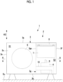
- Fig. 1 is a front view illustrating the outdoor unit 2 of the air conditioner 1 according to the first embodiment of the present disclosure.
- Fig. 2 is a plan view illustrating the outdoor unit 2 of the air conditioner 1 according to the first embodiment of the present disclosure.
- a direction orthogonal to an installation surface Su is referred to as a height direction HD.
- Fig. 3 is a cross-sectional view illustrating the outdoor unit 2 taken along a line A-A of Fig. 1 and illustrates a state in which vibration isolating members (a first vibration isolating member 100, a second vibration isolating member 200, and a third vibration isolating member 300) are attached.
- the air conditioner 1 includes a compressor 4 that compresses a refrigerant, a four-way switching valve (not illustrated) that switches a circulation direction of the refrigerant, an outdoor heat exchanger 5 that exchanges heat between the refrigerant and outside air, an expansion valve (not illustrated) that expands the refrigerant, and an indoor heat exchanger (not illustrated) that exchanges heat between the refrigerant and indoor air from an indoor fan (not illustrated) and has a refrigerant cycle which is a close cycle configured by connecting these devices with a refrigerant pipe 9.
- Various devices are accommodated in an indoor unit (not illustrated) or the outdoor unit 2.
- the outdoor unit 2 includes a housing 3, the compressor 4, the outdoor heat exchanger 5, a blower 6 that guides outside air to the outdoor heat exchanger 5, a control box 7, a support portion 8 that supports the control box 7 with respect to the housing 3, the refrigerant pipe 9, a fixing member (adjacent member) 10 that fixes the refrigerant pipe 9, a main accumulator 11, a sub-accumulator 12, and mufflers 13 and 14.
- the housing 3 is a member having a substantially rectangular parallelepiped shape that configures an outer shell of the outdoor unit 2 and has a space S formed therein.
- the control box 7 is a member that accommodates an electrical component, such as an inverter, that controls the compressor 4 and the like.
- the fixing member 10 is a member that is disposed to be adjacent to the compressor 4 and fixes the refrigerant pipe 9 to the housing 3. Each of the portions constituting the outdoor unit 2 is disposed in the space S.
- the housing 3 has a top panel 3a that defines an upper surface of the space S, a bottom panel 3b that defines a lower surface of the space S, a front panel 3c that defines a front surface (an end surface in one direction) of the space S, a rear panel 3d that defines a rear surface of the space S, a right panel 3e that defines a right surface of the space S, and a left panel 3f that defines a left surface of the space S.
- the housing 3 has a partition wall 3g that separates a heat exchanger room S1 in which the outdoor heat exchanger 5 and the like are disposed from a machine room S2 in which the compressor 4, the control box 7, and the like are disposed.
- the compressor 4 is a device that is accommodated in the machine room S2 of the space S and is disposed at a position facing the front panel 3c.
- the compressor 4 compresses the refrigerant circulating in the refrigerant cycle and discharges the refrigerant to the refrigerant pipe.
- Fig. 1 the illustration of other members disposed to be adjacent to the compressor 4 in the machine room S2 is omitted.
- Fig. 2 the illustration of some devices disposed in the machine room S2 is omitted.
- the front panel 3c is configured such that a portion or all of the front panel 3c is openable and closable.
- a discharge opening (not illustrated) through which the blower 6 discharges the outside air introduced into the outdoor unit 2 is formed in the front panel 3c.
- An introduction opening (not illustrated) for introducing the outside air into the outdoor unit 2 is formed in the rear panel 3d.
- the partition wall 3g is a member that is formed in a substantially L-shape in a plan view and includes a first partition wall 3ga that extends from the inner surface of the front panel 3c toward the outdoor heat exchanger 5 and a second partition wall 3gb that extends from an end portion, which is closer to the outdoor heat exchanger 5, in the first partition wall 3ga toward the left panel 3f.
- the heat exchanger room S1 has a space having a substantially L-shape in a plan view formed therein.
- the outdoor heat exchanger 5 having a substantially L-shape in a plan view is placed on the bottom panel 3b so as to follow the right panel 3e and the rear panel 3d.
- the blower 6 that guides the outside air to the outdoor heat exchanger 5 and an electric motor 6a that drives the blower 6 are disposed in the heat exchanger room S1.
- the machine room S2 is a space partitioned by the front panel 3c, the left panel 3f, and the partition wall 3g.
- the compressor 4 is placed on the bottom panel 3b in the machine room S2.
- the support portion 8 supported by the first partition wall 3ga is provided in an upper portion of the machine room S2.
- the control box 7 is suspended from the support portion 8 and is supported by the support portion 8.
- the refrigerant pipe 9 is a pipe for circulating the refrigerant through the refrigerant cycle.
- the refrigerant pipe 9 is a general term for the pipes provided in the machine room S2 in the outdoor unit 2.
- Figs. 1 and 2 illustrate the refrigerant pipe 9 that connects the compressor 4 and the muffler 14, but do not illustrate the other refrigerant pipes.
- the fixing member 10 is a member for fixing the refrigerant pipe 9 to the housing 3. As illustrated in Fig. 3 , one end of the fixing member 10 is fixed to the housing 3 by a fastening bolt 10a. As illustrated in Fig. 1 , the other end of the fixing member 10 extends to the bottom panel 3b in the height direction HD and is fixed to the bottom panel 3b by a fastening bolt (not illustrated).
- the main accumulator 11 and the sub-accumulator 12 are devices that are used to separate the refrigerant supplied to the compressor 4 into gas and liquid. As illustrated in Figs. 2 and 3 , the main accumulator 11 is disposed between the compressor 4 and the first partition wall 3ga in a plan view of the outdoor unit 2. The sub-accumulator 12 is disposed between the compressor 4 and the second partition wall 3gb in the plan view of the outdoor unit 2.
- the mufflers 13 and 14 are devices for reducing noise caused by the refrigerant circulated through the refrigerant pipe 9. As illustrated in Figs. 2 and 3 , the muffler 13 is disposed between the compressor 4 and the left panel 3f in the plan view of the outdoor unit 2. The muffler 13 is disposed between the compressor 4 and the first partition wall 3ga in the plan view of the outdoor unit 2.
- the partition wall 3g is attached to the housing 3 by fastening bolts (not illustrated). As illustrated in Figs. 2 and 3 , the partition wall 3g is disposed to be adjacent to the main accumulator 11 with a gap CL1 interposed between the partition wall 3g and the main accumulator 11 constituting the refrigerant device 20 in a horizontal direction parallel to the installation surface Su. In addition, the partition wall 3g is disposed to be adjacent to the muffler 14 with a gap CL2 interposed between the partition wall 3g and the muffler 14 constituting the refrigerant device 20 in the horizontal direction. Further, the partition wall 3g is disposed to be adjacent to the refrigerant pipe 9 with a gap CL3 interposed between the partition wall 3g and the refrigerant pipe 9 constituting the refrigerant device 20 in the horizontal direction.
- the fixing member 10 is attached to the housing 3 by the fastening bolt 10a. As illustrated in Figs. 2 and 3 , the fixing member 10 is disposed to be adjacent to the main accumulator 11 with a gap CL4 interposed between the fixing member 10 and the main accumulator 11 constituting the refrigerant device 20 in the horizontal direction parallel to the installation surface Su.
- the fixing member 10 is disposed to be adjacent to the compressor 4 with a gap CL5 interposed between the fixing member 10 and the compressor 4 constituting the refrigerant device 20 in the horizontal direction.
- the muffler 13 is attached to the housing 3 through the refrigerant pipe 9 and the fixing member 10. As illustrated in Figs. 2 and 3 , the muffler 13 is disposed to be adjacent to the compressor 4 with a gap CL6 interposed between the muffler 13 and the compressor 4 in the horizontal direction.
- the first vibration isolating member 100 and the second vibration isolating member 200 are attached to the refrigerant device 20 in order to prevent the refrigerant device 20 or the refrigerant pipe 9 connected to the refrigerant device 20 from being damaged due to the occurrence of stress in the refrigerant device 20 or the refrigerant pipe 9 caused by the displacement of the refrigerant device 20 disposed in the machine room S2 due to strong vibrations or impacts during transport.
- the first vibration isolating member 100 is attached to the refrigerant device 20 so as to cover the entire periphery of a side surface of the compressor 4 along a circumferential direction CD.
- the second vibration isolating member 200 is attached to the refrigerant device 20 so as to fill up at least the gaps CL1, CL2, CL3, CL4, CL5, and CL6.
- Fig. 4 is a cross-sectional view illustrating the outdoor unit 2 taken along the line A-A of Fig. 1 and illustrates a state in which the vibration isolating members (the first vibration isolating member 100, the second vibration isolating member 200, and the third vibration isolating member 300) are not attached.
- Fig. 5 is a cross-sectional view illustrating the outdoor unit taken along the line A-A of Fig. 1 and illustrates a state in which the first vibration isolating member 100 is attached.
- the first vibration isolating member 100 is attached to an area from a lower end to an upper end of the refrigerant device 20 in the height direction so as to cover the entire periphery of the compressor 4 and the main accumulator 11 in the state illustrated in Fig. 4 (first attachment step).
- first attachment step the first vibration isolating member 100 is brought into contact with at least a portion of the side surfaces of the compressor 4 and the main accumulator 11.
- the first vibration isolating member 100 is attached in a state of not being in contact with the partition wall 3g and the fixing member 10.
- the second vibration isolating member 200 is attached to at least a portion of the area from the lower end to the upper end of the refrigerant device 20 in the height direction HD so as to cover the entire periphery of the first vibration isolating member 100 in the state illustrated in Fig. 5 (second attachment step). In this way, the second vibration isolating member 200 is brought into contact with at least a portion of the first vibration isolating member 100.
- the second vibration isolating member 200 is attached so as to fill up the gaps CL1, CL2, and CL3 together with the first vibration isolating member 100 in a state of being in contact with both the first vibration isolating member 100 and the partition wall 3g.
- the second vibration isolating member 200 is attached so as to fill up the gaps CL4 and CL5 together with the first vibration isolating member 100 in a state of being in contact with both the first vibration isolating member 100 and the fixing member 10.
- the second vibration isolating member 200 is attached so as to fill up the gap CL6 together with the first vibration isolating member 100 in a state of being in contact with both the first vibration isolating member 100 and the muffler 13.
- the third vibration isolating member 300 is disposed so as to seal the upper sides of the compressor 4 and the main accumulator 11 covered with the first vibration isolating member 100.
- the lower sides of the compressor 4 and the main accumulator 11 are covered with the bottom panel 3b, the sides thereof are covered with the first vibration isolating member and the second vibration isolating member 200, and the upper sides thereof are covered with the third vibration isolating member 300 by disposing the third vibration isolating member 300.
- the third vibration isolating member 300 is made of, for example, felt obtained by compressing animal fibers or other fibers into a sheet shape. The state illustrated in Fig. 3 is set by performing the above-described work.
- the first vibration isolating member 100, the second vibration isolating member 200, and the third vibration isolating member 300 according to the present embodiment may be attached only during the transport of the outdoor unit 2 or may be attached not only during the transport of the outdoor unit 2 but also during the operation after the installation of the outdoor unit 2. Since the first vibration isolating member 100, the second vibration isolating member 200, and the third vibration isolating member 300 are attached to the refrigerant device 20 during the operation of the outdoor unit 2, it is possible to appropriately suppress the vibration and noise of the refrigerant device 20.
- Fig. 6 is a plan view illustrating the first vibration isolating member 100.
- Fig. 7 is a cross-sectional view illustrating the first vibration isolating member 100 taken along a line B-B of Fig. 6 .
- the first vibration isolating member 100 is a member formed in a long shape in which a length L12 in a longitudinal direction LD is larger than a length L11 in the height direction HD.
- the first vibration isolating member 100 is configured by laminating a first inner layer 110 and a first outer layer 120. The first inner layer 110 and the first outer layer 120 are joined to each other by, for example, an adhesive.
- the first inner layer 110 is a member that is disposed in contact with the compressor 4 and the main accumulator 11.
- the first outer layer 120 is a member that is disposed in contact with the first inner layer 110 and the second vibration isolating member 200.
- the length of the first inner layer 110 in the longitudinal direction LD is smaller than the length of the first outer layer 120 in the longitudinal direction LD. This is for joining a first end portion 120a of the first outer layer 120 in the longitudinal direction LD and a second end portion 120b of the first outer layer 120 in the longitudinal direction LD with an adhesive or the like.
- the first inner layer 110 is made of, for example, felt obtained by compressing animal fibers or other fibers into a sheet shape.
- the first outer layer 120 is made of a material (for example, a rubber material) that exhibits high sound insulation properties.
- the first inner layer 110 may be made of another member having a lower rigidity than the rubber material.
- a modification example may be adopted in which the first inner layer 110 is made of a rubber material and the first outer layer 120 is made of another material having a lower rigidity than the rubber material.
- Fig. 8 is a cross-sectional view illustrating a state in which the first vibration isolating member 100 is attached to the compressor 4 and the main accumulator 11. As illustrated in Fig. 8 , the first vibration isolating member 100 is disposed so as to cover the compressor 4 and the main accumulator 11 along the circumferential direction CD in a state of being in contact with a portion of a side surface 4a of the compressor 4 and a portion of a side surface 11a of the main accumulator 11.
- the first end portion 120a of the first outer layer 120 in the longitudinal direction LD and the second end portion 120b of the first outer layer 120 in the longitudinal direction LD are joined with an adhesive or the like to maintain the state in which the first vibration isolating member 100 covers the compressor 4 and the main accumulator 11.
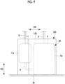
- Fig. 9 is a front view illustrating a state in which the first vibration isolating member 100 is attached to the compressor 4 and the main accumulator 11. As illustrated in Fig. 9 , the first vibration isolating member 100 is disposed in an area from the lower ends to the upper ends of the compressor 4 and the main accumulator 11 in the height direction HD.
- the first vibration isolating member 100 is disposed so as not to come into contact with the partition wall 3g, the fixing member 10, the refrigerant pipe 9, and the muffler 14 disposed adjacent thereto in a state in which the first vibration isolating member 100 is attached to the compressor 4 and the main accumulator 11.
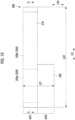
- Fig. 10 is a plan view illustrating the second vibration isolating member 200.
- Fig. 11 is a cross-sectional view illustrating the second vibration isolating member 200 taken along a line C-C of Fig. 10 .
- the second vibration isolating member 200 is a member formed in a long shape in which a length L22 in the longitudinal direction LD is larger than a length L21 in the height direction HD.
- the second vibration isolating member 200 is configured by laminating a second inner layer 210, a second outer layer 220, and an intermediate layer 230 interposed between the second inner layer 210 and the second outer layer 220.
- the second inner layer 210 and the intermediate layer 230 are joined to each other by, for example, an adhesive, and the second outer layer 220 and the intermediate layer 230 are joined to each other by, for example, the adhesive.
- the second inner layer 210 is a member that is disposed in contact with the first vibration isolating member 100.
- the second outer layer 220 is a member that is disposed in contact with the second inner layer 210 and other adjacent members (for example, the partition wall 3g and the fixing member 10).
- the length of the second inner layer 210 in the longitudinal direction LD is smaller than the length L22 of the intermediate layer 230 in the longitudinal direction LD. This is for joining a first end portion 230a of the intermediate layer 230 in the longitudinal direction LD and a second end portion 230b of the intermediate layer 230 in the longitudinal direction LD.
- surface fasteners are attached to the first end portion 230a and the second end portion 230b. Since the first end portion 230a and the second end portion 230b are joined to each other by the surface fasteners, it is possible to appropriately switch between a state in which the first end portion 230a and the second end portion 230b are joined to each other and a state in which the first end portion 230a and the second end portion 230b are not joined to each other and thus to easily attach and detach the second vibration isolating member 200.
- the second inner layer 210 and the second outer layer 220 are made of, for example, felt obtained by compressing animal fibers or other fibers into a sheet shape.
- the intermediate layer 230 is made of a material (for example, a resin material such as vinyl chloride) having a higher rigidity than the second inner layer 210 and the second outer layer 220.
- the second inner layer 210 and the second outer layer 220 may be made of other members having a lower rigidity than the intermediate layer 230.
- the second outer layer 220 of the second vibration isolating member 200 includes a first member 220a having a first thickness Th1 and a second member 220b having a second thickness Th2 smaller than the first thickness Th1.
- the first thickness Th1 in a first circumferential direction area CA1 and the second thickness Th2 in a second circumferential direction area CA2 different from the first circumferential direction area CA1 in the circumferential direction CD surrounding the side surface of the refrigerant device 20 are different from each other in a state in which the second outer layer 220 is not disposed in the gaps CL1, CL2, CL3, CL4, CL5, and CL6.
- the first thickness Th1 and the second thickness Th2 of the second vibration isolating member 200 are adjusted such that the rigidity of the second vibration isolating member 200 in the first circumferential direction area CA1 is higher than the rigidity of the second vibration isolating member 200 in the second circumferential direction area CA2 in a state in which the second vibration isolating member 200 is attached to achieve a state suitable for reducing the rigidity of other adjacent members or a vibration frequency of the compressor.
- a modification example may be adopted in which the second outer layer 220 of the second vibration isolating member 200 is configured to have the same thickness in the entire area in the circumferential direction CD.
- the second vibration isolating member 200 is disposed so as to fill up the gaps CL1, CL2, and CL3 together with the first vibration isolating member 100 in a state of being in contact with both the first vibration isolating member 100 and the partition wall 3g.
- the second vibration isolating member 200 is disposed so as to fill up the gaps CL4 and CL5 together with the first vibration isolating member 100 in a state of being in contact with both the first vibration isolating member 100 and the fixing member 10.
- the second vibration isolating member 200 is disposed so as to fill up the gap CL6 together with the first vibration isolating member 100 in a state of being in contact with both the first vibration isolating member 100 and the muffler 13.
- Fig. 13 is a cross-sectional view illustrating a state in which the second vibration isolating member 200 is attached to the refrigerant device 20 at a position lower than the height at which the fixing member 10 is disposed.
- the intermediate layer 230 of the second vibration isolating member 200 is disposed so as to cover only a partial area, which is closer to the front panel 3c, in the entire periphery of the first vibration isolating member 100 at the position lower than the height at which the fixing member 10 is disposed.
- Fig. 14 is a front view illustrating a state in which the second vibration isolating member 200 is attached to the refrigerant device 20.
- the second vibration isolating member 200 is disposed in a portion of the area from the lower end to the upper end of the refrigerant device 20 in the height direction HD.
- the second inner layer 210 and the second outer layer 220 are disposed in a first area AR1, which is a partial area in the height direction HD, so as to cover the entire periphery of the side surface of the refrigerant device 20, with the intermediate layer 230 interposed therebetween.
- the intermediate layer 230 is disposed in a second area AR2 from the lower end of the refrigerant device 20 in the height direction HD to the first area AR1 so as to cover only a portion of the side surface of the refrigerant device 20.
- the reason why the intermediate layer 230 of the second vibration isolating member 200 is disposed so as to cover only a partial area closer to the front panel 3c is that, when the entire periphery of the first vibration isolating member 100 is covered with the second vibration isolating member 200, it is difficult to perform the work of attaching the second vibration isolating member 200.
- the reason is that, even when the intermediate layer 230 of the second vibration isolating member 200 does not cover the entire periphery of the first vibration isolating member 100, the intermediate layer 230 of the second vibration isolating member 200 can come into contact with the bottom panel 3b to reliably fix the position of the second vibration isolating member 200 in the height direction HD.
- the position of an end portion of the second area AR2 in the longitudinal direction LD in the height direction HD of the intermediate layer 230 is different from the position of an end portion of the first area AR1 in the longitudinal direction LD in the height direction HD of the first member 220a of the second outer layer 220.
- a boundary between the first member 220a and the second member 220b is not disposed at the same position as the end portion of the second area AR2 in the height direction HD of the intermediate layer 230.
- the end portion of the second area AR2 in the height direction HD of the intermediate layer 230 is a stress concentration point. Therefore, when the boundary is not disposed at this point, it is possible to suppress the deformation or damage of the intermediate layer 230 due to stress concentration.
- the outdoor unit 2 according to the present embodiment described above has the following operation and effect.
- the first vibration isolating member 100 is disposed in the area from the lower end to the upper end of the refrigerant device 20 in the height direction HD so as to cover the entire periphery of the side surface of the refrigerant device 20 in a state of being in contact with at least a portion of the side surface of the refrigerant device 20. Therefore, it is possible to appropriately prevent vibrations and noise during the operation of the refrigerant device 20 including the compressor 4 from being transmitted to the outside.
- the second vibration isolating member 200 is disposed in at least a portion of the area from the lower end to the upper end in the height direction HD so as to cover the entire periphery of the first vibration isolating member 100 in a state of being in contact with at least a portion of the first vibration isolating member 100.
- the second vibration isolating member 200 is disposed so as to fill up the gaps CL1, CL2, CL3, CL4, CL5, and CL6 between the refrigerant device 20 and adjacent members together with the first vibration isolating member 100 in a state of being in contact with both the first vibration isolating member 100 and the adjacent members (the partition wall 3g and the fixing member 10).
- the gaps between the refrigerant device 20 and the adjacent members are filled with the first vibration isolating member 100 and the second vibration isolating member 200. Therefore, it is possible to appropriately prevent the refrigerant device 20 including the compressor 4 or the pipe connected to the refrigerant device 20 from being damaged due to the occurrence of stress in the refrigerant device 20 or the pipe caused by the displacement of the refrigerant device 20 due to strong vibrations or impacts during transport.
- the second vibration isolating member 200 in the second vibration isolating member 200, the first thickness Th1 in the first circumferential direction area CA1 and the second thickness Th2 in the second circumferential direction area CA2 in the circumferential direction CD are different from each other. Therefore, the second vibration isolating member 200 can have an appropriate thickness according to, for example, the distances of the gaps in the first circumferential direction area CA1 and the second circumferential direction area CA2 when the second vibration isolating member 200 is attached or the rigidity of adjacent members in the first circumferential direction area CA1 and the second circumferential direction area CA2.
- the thickness of the second vibration isolating member 200 can be adjusted such that the rigidity of the second vibration isolating member 200 in the first circumferential direction area CA1 is higher than the rigidity of the second vibration isolating member 200 in the second circumferential direction area CA2 in a state in which the second vibration isolating member 200 is attached to achieve a state suitable for reducing the rigidity of adjacent members or the vibration frequency of the compressor 4.
- one of the first inner layer 110 and the first outer layer 120 of the first vibration isolating member 100 is made of the rubber material. Therefore, it is possible to sufficiently ensure the vibration isolation performance and the sound insulation performance.
- the other of the first inner layer 110 and the first outer layer 120 of the first vibration isolating member 100 is made of a member having a lower rigidity than the rubber material. Therefore, it is possible to appropriately absorb the external force applied to the refrigerant device 20 including the compressor 4 due to strong vibrations or impacts.
- the second inner layer 210 and the second outer layer 220 of the second vibration isolating member 200 are disposed in the first area AR1, which is a partial area of the refrigerant device 20 in the height direction HD, so as to cover the entire periphery of the side surface of the refrigerant device 20 with the intermediate layer 230 interposed therebetween. Since the entire periphery of the side surface of the refrigerant device 20 is covered with the second vibration isolating member 200, it is possible to reliably prevent a space from being formed in the gaps between the side surface of the refrigerant device 20 and adjacent members.
- the first vibration isolating member is attached to the area from the lower end to the upper end of the refrigerant device 20 in the height direction HD so as to cover the entire periphery of the side surface of the refrigerant device 20 in a state of being in contact with at least a portion of the side surface of the refrigerant device 20. Therefore, it is possible to appropriately prevent the vibration and noise during the operation of the refrigerant device including the compressor from being transmitted to the outside.
- the second vibration isolating member 200 is attached to at least a portion of the area from the lower end to the upper end of the refrigerant device in the height direction so as to cover the entire periphery of the first vibration isolating member in a state of being in contact with at least a portion of the first vibration isolating member.
- the second vibration isolating member 200 is attached so as to fill up the gaps CL1, CL2, CL3, CL4, CL5, and CL6 between the side surface of the refrigerant device 20 and adjacent members together with the first vibration isolating member 100 in a state of being in contact with both the first vibration isolating member 100 and the adjacent members.
- the refrigerant device 20 including the compressor or the pipe connected to the refrigerant device 20 from being damaged due to the occurrence of stress in the refrigerant device 20 or the pipe caused by the displacement of the refrigerant device 20 due to strong vibrations or impacts during transport.
- Fig. 15 is a cross-sectional view illustrating the outdoor unit 2A according to the second embodiment of the present disclosure and illustrates a state in which vibration isolating members (the first vibration isolating member 100, the second vibration isolating member 200, and the third vibration isolating member 300) are attached.
- the first vibration isolating member 100 and the second vibration isolating member 200 are disposed so as to fill up the gap CL6 between the compressor 4 and the muffler 13.
- the first vibration isolating member 100 and the second vibration isolating member 200 are disposed so as to fill up a gap CL7 between the muffler 13 and the left panel 3f.
- the first vibration isolating member 100 and the second vibration isolating member 200 are disposed so as to fill up the gap CL7 between the muffler 13 and the left panel 3f. Since the left panel 3f is a member constituting a portion of the housing 3, it is possible to reliably transmit the vibration of the refrigerant device 20 to the left panel 3f through the muffler 13 and to absorb the vibration of the refrigerant device 20.
- the vibration of the refrigerant device 20 in a left-right direction in Fig. 15 is transmitted to the left panel 3f and the partition wall 3g. Therefore, the vibration in the left-right direction can be reliably absorbed by the housing 3.
- the vibration of the refrigerant device 20 in a front-rear direction in Fig. 15 is transmitted to the fixing member 10 and the partition wall 3g. Therefore, the vibration in the front-rear direction can be reliably absorbed by the housing 3.
- the compressing device (2) according to each of the above-described embodiments is understood as follows.
- a compressing device including: a housing (3) which has a space (S) formed therein and in which a panel (3c) defining an end surface of the space in one direction is openable and closable; a refrigerant device (20) that is accommodated in the space, is disposed at a position facing the panel, and includes a compressor (4) compressing a refrigerant; an adjacent member (3g or 10) that is attached to the housing and is disposed to be adjacent to the refrigerant device with a gap (CL1, CL2, or CL3) interposed between the adjacent member and the refrigerant device in a horizontal direction; a first vibration isolating member (100) that is disposed in an area from a lower end to an upper end of the compressor in a height direction (HD) so as to cover an entire periphery of the compressor in a state of being in contact with at least a portion of a side surface of the compressor; and a second vibration isolating member (200
- the first vibration isolating member is disposed in a state of not being in contact with the adjacent member, and the second vibration isolating member is disposed so as to fill up the gap together with the first vibration isolating member in a state of being in contact with both the first vibration isolating member and the adjacent member.
- the first vibration isolating member is disposed in the area from the lower end to the upper end of the compressor in the height direction so as to cover the entire periphery of the compressor in a state of being in contact with at least a portion of the side surface of the compressor. Therefore, it is possible to appropriately prevent vibrations and noise during the operation of the compressor from being transmitted to the outside.
- the second vibration isolating member is disposed in at least a portion of the area from the lower end to the upper end in the height direction so as to cover the entire periphery of the first vibration isolating member in a state of being in contact with at least a portion of the first vibration isolating member.
- the second vibration isolating member is disposed so as to fill up the gap between the refrigerant device and the adjacent member together with the first vibration isolating member in a state of being in contact with both the first vibration isolating member and the adjacent member.
- the gap between the refrigerant device and the adjacent member is filled with the first vibration isolating member and the second vibration isolating member, it is possible to appropriately prevent the refrigerant device including the compressor or the pipe connected to the refrigerant device from being damaged due to the occurrence of stress in the refrigerant device or the pipe caused by the displacement of the refrigerant device due to strong vibrations or impacts during transport.
- the compressing device further includes the following configuration. That is, in the second vibration isolating member, a first thickness (Th1) in a first circumferential direction area (CA1) in a circumferential direction surrounding a side surface of the refrigerant device is different from a second thickness (Th2) in a second circumferential direction area (CA2) different from the first circumferential direction area in a state in which the second vibration isolating member is not disposed in the gap.
- a first thickness (Th1) in a first circumferential direction area (CA1) in a circumferential direction surrounding a side surface of the refrigerant device is different from a second thickness (Th2) in a second circumferential direction area (CA2) different from the first circumferential direction area in a state in which the second vibration isolating member is not disposed in the gap.
- the first thickness in the first circumferential direction area and the second thickness in the second circumferential direction area in the circumferential direction of the second vibration isolating member are different from each other. Therefore, the second vibration isolating member can have an appropriate thickness according to, for example, the distances of the gaps in the first circumferential direction area and the second circumferential direction area when the second vibration isolating member is attached or the rigidity of the adjacent member in the first circumferential direction area and the second circumferential direction area.
- the thickness of the second vibration isolating member can be adjusted such that the rigidity of the second vibration isolating member in the first circumferential direction area is higher than the rigidity of the second vibration isolating member in the second circumferential direction area in a state in which the second vibration isolating member is attached to achieve a state suitable for reducing the rigidity of the adjacent member or the vibration frequency of the compressor.
- the compressing device according to the first or second aspect further includes the following configuration. That is, the first vibration isolating member is configured by laminating a first inner layer (110) that is disposed in contact with the refrigerant device and a first outer layer (120) that is disposed in contact with the first inner layer and the second vibration isolating member.
- the first inner layer and the first outer layer is made of a rubber material
- the other of the first inner layer and the first outer layer is made of a member having a lower rigidity than the rubber material.
- the compressing device of the third aspect of the present disclosure since one of the first inner layer and the first outer layer of the first vibration isolating member is made of the rubber material, it is possible to sufficiently ensure the vibration isolation performance and the sound insulation performance.
- the other of the first inner layer and the first outer layer of the first vibration isolating member is made of the member having a lower rigidity than the rubber material, it is possible to appropriately absorb the external force applied to the refrigerant device including the compressor due to strong vibrations or impacts.
- the compressing device according to any one of the first to third aspects further includes the following configuration. That is, the second vibration isolating member is configured by laminating a second inner layer (210) that is disposed in contact with the first vibration isolating member, a second outer layer (220) that is disposed in contact with the adjacent member, and an intermediate layer (230) that is interposed between the second inner layer and the second outer layer.
- the second inner layer and the second outer layer are disposed in a first area (AR1), which is a partial area of the refrigerant device in the height direction, so as to cover the entire periphery of the side surface of the refrigerant device, with the intermediate layer interposed therebetween.
- AR1 a first area of the refrigerant device in the height direction
- the intermediate layer has a higher rigidity than the second inner layer and the second outer layer and is disposed in a second area (AR2) from a lower end of the refrigerant device in the height direction to the first area so as to cover only a portion of the side surface of the compressor.
- the second inner layer and the second outer layer of the second vibration isolating member are disposed in the first area, which is a partial area of the refrigerant device in the height direction, so as to cover the entire periphery of the side surface of the refrigerant device with the intermediate layer interposed therebetween. Since the entire periphery of the side surface of the refrigerant device is covered with the second vibration isolating member, it is possible to reliably prevent a space from being formed in the gap between the side surface of the refrigerant device and the adjacent member.
- the intermediate layer having a higher rigidity than the second inner layer and the second outer layer is disposed in the second area from the lower end of the refrigerant device in the height direction to the first area. Therefore, the second vibration isolating member is positioned in the height direction with respect to the bottom surface on which the compressor is installed by the intermediate layer. In addition, the first vibration isolating member that comes into contact with the second vibration isolating member is also positioned in the height direction.
- the second vibration isolating member can be easily attached around the first vibration isolating member, as compared to a case where the intermediate layer is disposed so as to cover the entire periphery of the side surface of the refrigerant device.
- a vibration isolating member attachment method for attaching a vibration isolating member to a refrigerant device including a compressor accommodated in a compressing device.
- the compressing device includes: a housing which has a space formed therein and in which a panel defining an end surface of the space in one direction is openable and closable; a refrigerant device that is accommodated in the space, is disposed at a position facing the panel, and includes the compressor compressing a refrigerant; and an adjacent member that is attached to the housing and is disposed to be adjacent to the refrigerant device with a gap interposed between the adjacent member and the refrigerant device in a horizontal direction.
- the vibration isolating member attachment method includes: a first attachment step of attaching a first vibration isolating member to an area from a lower end to an upper end of the compressor in a height direction so as to cover an entire periphery of the compressor to come into contact with at least a portion of a side surface of the compressor; and a second attachment step of attaching a second vibration isolating member to at least a portion of an area from a lower end to an upper end of the refrigerant device in the height direction so as to cover an entire periphery of the first vibration isolating member to come into contact with at least a portion of the first vibration isolating member.
- the first vibration isolating member is attached in a state of not being in contact with the adjacent member.
- the second vibration isolating member is attached so as to fill up the gap together with the first vibration isolating member in a state of being in contact with both the first vibration isolating member and the adjacent member.
- the first vibration isolating member is attached to the area from the lower end to the upper end of the compressor in the height direction HD so as to cover the entire periphery of the compressor in a state of being in contact with at least a portion of the side surface of the compressor. Therefore, it is possible to appropriately prevent vibrations and noise during the operation of the compressor from being transmitted to the outside.
- the second vibration isolating member is attached to at least a portion of the area from the lower end to the upper end of the refrigerant device in the height direction so as to cover the entire periphery of the first vibration isolating member in a state of being in contact with at least a portion of the first vibration isolating member.
- the second vibration isolating member is attached so as to fill up the gap between the side surface of the refrigerant device and the adjacent member together with the first vibration isolating member in a state of being in contact with both the first vibration isolating member and the adjacent member.
- the gap between the side surface of the refrigerant device and the adjacent member is filled with the first vibration isolating member and the second vibration isolating member, it is possible to appropriately prevent the refrigerant device including the compressor or the pipe connected to the refrigerant device from being damaged due to the occurrence of stress in the refrigerant device or the pipe caused by the displacement of the refrigerant device due to strong vibrations or impacts during transport.
Landscapes
- Engineering & Computer Science (AREA)
- General Engineering & Computer Science (AREA)
- Mechanical Engineering (AREA)
- Chemical & Material Sciences (AREA)
- Acoustics & Sound (AREA)
- Physics & Mathematics (AREA)
- Combustion & Propulsion (AREA)
- Aviation & Aerospace Engineering (AREA)
- Multimedia (AREA)
- Compressor (AREA)
- Vibration Prevention Devices (AREA)
- Soundproofing, Sound Blocking, And Sound Damping (AREA)
- Other Air-Conditioning Systems (AREA)
Abstract
Description
- The present disclosure relates to a compressing device and a vibration isolating member attachment method.
- In the related art, a compressor attachment device is known in which a sound and vibration isolating cover for accommodating a compressor and an accumulator is fixed to a bottom plate in order to prevent the compressor from colliding with other components and being damaged due to large vibrations or impacts during transport (for example, see PTL 1). In the attachment device disclosed in
PTL 1, the compressor and the accumulator are fixed to a support plate to maintain a gap therebetween. The compressor and the accumulator are accommodated in the sound and vibration isolating cover to be sealed. In this way, the compressor is prevented from colliding with other components and being damaged. - [PTL 1]
Japanese Unexamined Patent Application Publication No. 8-36389 - However, in the attachment device disclosed in
PTL 1, since a space is present outside the sound and vibration isolating cover, there is a possibility that the compressor will be displaced due to strong vibrations or impacts during transport of the compressor and stress will occur in a pipe connected to the compressor, resulting in damage of the pipe or the like. - The present disclosure has been made in view of these circumstances, and an object of the present disclosure is to provide a compressing device and a vibration isolating member attachment method that can appropriately prevent a refrigerant device including a compressor or a pipe connected to the refrigerant device from being damaged due to occurrence of stress in the refrigerant device or the pipe caused by displacement of the refrigerant device due to strong vibrations or impacts during transport.
- In order to achieve the object, according to the present disclosure, there is provided a compressing device including: a housing which has a space formed therein and in which a panel defining an end surface of the space in one direction is openable and closable; a refrigerant device that is accommodated in the space, is disposed at a position facing the panel, and includes a compressor compressing a refrigerant; an adjacent member that is attached to the housing and is disposed to be adjacent to the refrigerant device with a gap interposed between the adjacent member and the refrigerant device in a horizontal direction; a first vibration isolating member that is disposed in an area from a lower end to an upper end of the compressor in a height direction so as to cover an entire periphery of the compressor in a state of being in contact with at least a portion of a side surface of the compressor; and a second vibration isolating member that is disposed in at least a portion of an area from a lower end to an upper end of the refrigerant device in the height direction so as to cover an entire periphery of the first vibration isolating member in a state of being in contact with at least a portion of the first vibration isolating member. The first vibration isolating member is disposed in a state of not being in contact with the adjacent member, and the second vibration isolating member is disposed so as to fill up the gap together with the first vibration isolating member in a state of being in contact with both the first vibration isolating member and the adjacent member.
- In addition, according to the present disclosure, there is provided a vibration isolating member attachment method for attaching a vibration isolating member to a refrigerant device including a compressor accommodated in a compressing device. The compressing device includes a housing which has a space formed therein and in which a panel defining an end surface of the space in one direction is openable and closable, a refrigerant device that is accommodated in the space, is disposed at a position facing the panel, and includes the compressor compressing a refrigerant, and an adjacent member that is attached to the housing and is disposed to be adjacent to the refrigerant device with a gap interposed between the adjacent member and the refrigerant device in a horizontal direction. The vibration isolating member attachment method includes: a first attachment step of attaching a first vibration isolating member to an area from a lower end to an upper end of the compressor in a height direction so as to cover an entire periphery of the compressor to come into contact with at least a portion of a side surface of the compressor; and a second attachment step of attaching a second vibration isolating member to at least a portion of an area from a lower end to an upper end of the refrigerant device in the height direction so as to cover an entire periphery of the first vibration isolating member to come into contact with at least a portion of the first vibration isolating member. In the first attachment step, the first vibration isolating member is attached in a state of not being in contact with the adjacent member. In the second attachment step, the second vibration isolating member is attached so as to fill up the gap together with the first vibration isolating member in a state of being in contact with both the first vibration isolating member and the adjacent member.
- According to the present disclosure, it is possible to provide a compressing device and a vibration isolating member attachment method that can appropriately prevent a refrigerant device including a compressor or a pipe connected to the refrigerant device from being damaged due to occurrence of stress in the refrigerant device or the pipe caused by displacement of the refrigerant device due to strong vibrations or impacts during transport.
-
-
Fig. 1 is a front view illustrating an outdoor unit of an air conditioner according to a first embodiment of the present disclosure. -
Fig. 2 is a plan view illustrating the outdoor unit of the air conditioner according to the first embodiment of the present disclosure. -
Fig. 3 is a cross-sectional view illustrating the outdoor unit taken along a line A-A ofFig. 1 and illustrates a state in which vibration isolating members are attached. -
Fig. 4 is a cross-sectional view illustrating the outdoor unit taken along the line A-A ofFig. 1 and illustrates a state in which the vibration isolating members are not attached. -
Fig. 5 is a cross-sectional view illustrating the outdoor unit taken along the line A-A ofFig. 1 and illustrates a state in which a first vibration isolating member is attached. -
Fig. 6 is a plan view illustrating the first vibration isolating member. -
Fig. 7 is a cross-sectional view illustrating the first vibration isolating member taken along a line B-B ofFig. 6 . -
Fig. 8 is a cross-sectional view illustrating a state in which the first vibration isolating member is attached to a compressor and a main accumulator. -
Fig. 9 is a front view illustrating a state in which the first vibration isolating member is attached to the compressor and the main accumulator. -
Fig. 10 is a plan view illustrating a second vibration isolating member. -
Fig. 11 is a cross-sectional view illustrating the second vibration isolating member taken along a line C-C ofFig. 10 . -
Fig. 12 is a cross-sectional view illustrating a state in which the second vibration isolating member is attached to a refrigerant device at a height at which a fixing member is disposed. -
Fig. 13 is a cross-sectional view illustrating a state in which the second vibration isolating member is attached to the refrigerant device at a position lower than the height at which the fixing member is disposed. -
Fig. 14 is a front view illustrating a state in which the second vibration isolating member is attached to the refrigerant device. -
Fig. 15 is a cross-sectional view illustrating an outdoor unit according to a second embodiment of the present disclosure and illustrates a state in which vibration isolating members are attached. - Hereinafter, an outdoor unit (compressing device) 2 of an
air conditioner 1 according to a first embodiment of the present disclosure will be described with reference to the drawings.Fig. 1 is a front view illustrating theoutdoor unit 2 of theair conditioner 1 according to the first embodiment of the present disclosure.Fig. 2 is a plan view illustrating theoutdoor unit 2 of theair conditioner 1 according to the first embodiment of the present disclosure. InFig. 1 , a direction orthogonal to an installation surface Su is referred to as a height direction HD.Fig. 3 is a cross-sectional view illustrating theoutdoor unit 2 taken along a line A-A ofFig. 1 and illustrates a state in which vibration isolating members (a firstvibration isolating member 100, a secondvibration isolating member 200, and a third vibration isolating member 300) are attached. - The
air conditioner 1 according to the present embodiment includes acompressor 4 that compresses a refrigerant, a four-way switching valve (not illustrated) that switches a circulation direction of the refrigerant, anoutdoor heat exchanger 5 that exchanges heat between the refrigerant and outside air, an expansion valve (not illustrated) that expands the refrigerant, and an indoor heat exchanger (not illustrated) that exchanges heat between the refrigerant and indoor air from an indoor fan (not illustrated) and has a refrigerant cycle which is a close cycle configured by connecting these devices with arefrigerant pipe 9. Various devices are accommodated in an indoor unit (not illustrated) or theoutdoor unit 2. - As illustrated in
Figs. 1 and2 , theoutdoor unit 2 includes ahousing 3, thecompressor 4, theoutdoor heat exchanger 5, ablower 6 that guides outside air to theoutdoor heat exchanger 5, acontrol box 7, asupport portion 8 that supports thecontrol box 7 with respect to thehousing 3, therefrigerant pipe 9, a fixing member (adjacent member) 10 that fixes therefrigerant pipe 9, amain accumulator 11, asub-accumulator 12, andmufflers - The
housing 3 is a member having a substantially rectangular parallelepiped shape that configures an outer shell of theoutdoor unit 2 and has a space S formed therein. Thecontrol box 7 is a member that accommodates an electrical component, such as an inverter, that controls thecompressor 4 and the like. Thefixing member 10 is a member that is disposed to be adjacent to thecompressor 4 and fixes therefrigerant pipe 9 to thehousing 3. Each of the portions constituting theoutdoor unit 2 is disposed in the space S. - The
housing 3 has atop panel 3a that defines an upper surface of the space S, abottom panel 3b that defines a lower surface of the space S, afront panel 3c that defines a front surface (an end surface in one direction) of the space S, arear panel 3d that defines a rear surface of the space S, aright panel 3e that defines a right surface of the space S, and aleft panel 3f that defines a left surface of the space S. Thehousing 3 has apartition wall 3g that separates a heat exchanger room S1 in which theoutdoor heat exchanger 5 and the like are disposed from a machine room S2 in which thecompressor 4, thecontrol box 7, and the like are disposed. - The
compressor 4 is a device that is accommodated in the machine room S2 of the space S and is disposed at a position facing thefront panel 3c. Thecompressor 4 compresses the refrigerant circulating in the refrigerant cycle and discharges the refrigerant to the refrigerant pipe. InFig. 1 , the illustration of other members disposed to be adjacent to thecompressor 4 in the machine room S2 is omitted. InFig. 2 , the illustration of some devices disposed in the machine room S2 is omitted. - The
front panel 3c is configured such that a portion or all of thefront panel 3c is openable and closable. A discharge opening (not illustrated) through which theblower 6 discharges the outside air introduced into theoutdoor unit 2 is formed in thefront panel 3c. An introduction opening (not illustrated) for introducing the outside air into theoutdoor unit 2 is formed in therear panel 3d. - The
partition wall 3g is a member that is formed in a substantially L-shape in a plan view and includes a first partition wall 3ga that extends from the inner surface of thefront panel 3c toward theoutdoor heat exchanger 5 and a second partition wall 3gb that extends from an end portion, which is closer to theoutdoor heat exchanger 5, in the first partition wall 3ga toward theleft panel 3f. - The heat exchanger room S1 has a space having a substantially L-shape in a plan view formed therein. In the heat exchanger room S1, the
outdoor heat exchanger 5 having a substantially L-shape in a plan view is placed on thebottom panel 3b so as to follow theright panel 3e and therear panel 3d. Theblower 6 that guides the outside air to theoutdoor heat exchanger 5 and anelectric motor 6a that drives theblower 6 are disposed in the heat exchanger room S1. - The machine room S2 is a space partitioned by the
front panel 3c, theleft panel 3f, and thepartition wall 3g. Thecompressor 4 is placed on thebottom panel 3b in the machine room S2. Thesupport portion 8 supported by the first partition wall 3ga is provided in an upper portion of the machine room S2. Thecontrol box 7 is suspended from thesupport portion 8 and is supported by thesupport portion 8. - The
refrigerant pipe 9 is a pipe for circulating the refrigerant through the refrigerant cycle. Therefrigerant pipe 9 is a general term for the pipes provided in the machine room S2 in theoutdoor unit 2.Figs. 1 and2 illustrate therefrigerant pipe 9 that connects thecompressor 4 and themuffler 14, but do not illustrate the other refrigerant pipes. - The fixing
member 10 is a member for fixing therefrigerant pipe 9 to thehousing 3. As illustrated inFig. 3 , one end of the fixingmember 10 is fixed to thehousing 3 by afastening bolt 10a. As illustrated inFig. 1 , the other end of the fixingmember 10 extends to thebottom panel 3b in the height direction HD and is fixed to thebottom panel 3b by a fastening bolt (not illustrated). - The
main accumulator 11 and the sub-accumulator 12 are devices that are used to separate the refrigerant supplied to thecompressor 4 into gas and liquid. As illustrated inFigs. 2 and3 , themain accumulator 11 is disposed between thecompressor 4 and the first partition wall 3ga in a plan view of theoutdoor unit 2. The sub-accumulator 12 is disposed between thecompressor 4 and the second partition wall 3gb in the plan view of theoutdoor unit 2. - The
mufflers refrigerant pipe 9. As illustrated inFigs. 2 and3 , themuffler 13 is disposed between thecompressor 4 and theleft panel 3f in the plan view of theoutdoor unit 2. Themuffler 13 is disposed between thecompressor 4 and the first partition wall 3ga in the plan view of theoutdoor unit 2. - As illustrated in
Figs. 2 and3 , thecompressor 4, themain accumulator 11, the sub-accumulator 12, and themufflers refrigerant device 20. The devices constituting therefrigerant device 20 are connected through therefrigerant pipe 9. - The
partition wall 3g is attached to thehousing 3 by fastening bolts (not illustrated). As illustrated inFigs. 2 and3 , thepartition wall 3g is disposed to be adjacent to themain accumulator 11 with a gap CL1 interposed between thepartition wall 3g and themain accumulator 11 constituting therefrigerant device 20 in a horizontal direction parallel to the installation surface Su. In addition, thepartition wall 3g is disposed to be adjacent to themuffler 14 with a gap CL2 interposed between thepartition wall 3g and themuffler 14 constituting therefrigerant device 20 in the horizontal direction. Further, thepartition wall 3g is disposed to be adjacent to therefrigerant pipe 9 with a gap CL3 interposed between thepartition wall 3g and therefrigerant pipe 9 constituting therefrigerant device 20 in the horizontal direction. - The fixing
member 10 is attached to thehousing 3 by thefastening bolt 10a. As illustrated inFigs. 2 and3 , the fixingmember 10 is disposed to be adjacent to themain accumulator 11 with a gap CL4 interposed between the fixingmember 10 and themain accumulator 11 constituting therefrigerant device 20 in the horizontal direction parallel to the installation surface Su. - In addition, the fixing
member 10 is disposed to be adjacent to thecompressor 4 with a gap CL5 interposed between the fixingmember 10 and thecompressor 4 constituting therefrigerant device 20 in the horizontal direction. - The
muffler 13 is attached to thehousing 3 through therefrigerant pipe 9 and the fixingmember 10. As illustrated inFigs. 2 and3 , themuffler 13 is disposed to be adjacent to thecompressor 4 with a gap CL6 interposed between themuffler 13 and thecompressor 4 in the horizontal direction. - In the present embodiment, the first
vibration isolating member 100 and the secondvibration isolating member 200 are attached to therefrigerant device 20 in order to prevent therefrigerant device 20 or therefrigerant pipe 9 connected to therefrigerant device 20 from being damaged due to the occurrence of stress in therefrigerant device 20 or therefrigerant pipe 9 caused by the displacement of therefrigerant device 20 disposed in the machine room S2 due to strong vibrations or impacts during transport. The firstvibration isolating member 100 is attached to therefrigerant device 20 so as to cover the entire periphery of a side surface of thecompressor 4 along a circumferential direction CD. The secondvibration isolating member 200 is attached to therefrigerant device 20 so as to fill up at least the gaps CL1, CL2, CL3, CL4, CL5, and CL6. - Next, the first
vibration isolating member 100, the secondvibration isolating member 200, and the thirdvibration isolating member 300 attached to therefrigerant device 20 according to the present embodiment will be described with reference to the drawings.Fig. 4 is a cross-sectional view illustrating theoutdoor unit 2 taken along the line A-A ofFig. 1 and illustrates a state in which the vibration isolating members (the firstvibration isolating member 100, the secondvibration isolating member 200, and the third vibration isolating member 300) are not attached.Fig. 5 is a cross-sectional view illustrating the outdoor unit taken along the line A-A ofFig. 1 and illustrates a state in which the firstvibration isolating member 100 is attached. - When the first
vibration isolating member 100, the secondvibration isolating member 200, and the thirdvibration isolating member 300 are attached to therefrigerant device 20 according to the present embodiment, the following procedure is performed. First, the firstvibration isolating member 100 is attached to an area from a lower end to an upper end of therefrigerant device 20 in the height direction so as to cover the entire periphery of thecompressor 4 and themain accumulator 11 in the state illustrated inFig. 4 (first attachment step). In this way, the firstvibration isolating member 100 is brought into contact with at least a portion of the side surfaces of thecompressor 4 and themain accumulator 11. In this step, the firstvibration isolating member 100 is attached in a state of not being in contact with thepartition wall 3g and the fixingmember 10. - Second, the second
vibration isolating member 200 is attached to at least a portion of the area from the lower end to the upper end of therefrigerant device 20 in the height direction HD so as to cover the entire periphery of the firstvibration isolating member 100 in the state illustrated inFig. 5 (second attachment step). In this way, the secondvibration isolating member 200 is brought into contact with at least a portion of the firstvibration isolating member 100. - At this time, the second
vibration isolating member 200 is attached so as to fill up the gaps CL1, CL2, and CL3 together with the firstvibration isolating member 100 in a state of being in contact with both the firstvibration isolating member 100 and thepartition wall 3g. In addition, the secondvibration isolating member 200 is attached so as to fill up the gaps CL4 and CL5 together with the firstvibration isolating member 100 in a state of being in contact with both the firstvibration isolating member 100 and the fixingmember 10. Further, the secondvibration isolating member 200 is attached so as to fill up the gap CL6 together with the firstvibration isolating member 100 in a state of being in contact with both the firstvibration isolating member 100 and themuffler 13. - Third, the third
vibration isolating member 300 is disposed so as to seal the upper sides of thecompressor 4 and themain accumulator 11 covered with the firstvibration isolating member 100. The lower sides of thecompressor 4 and themain accumulator 11 are covered with thebottom panel 3b, the sides thereof are covered with the first vibration isolating member and the secondvibration isolating member 200, and the upper sides thereof are covered with the thirdvibration isolating member 300 by disposing the thirdvibration isolating member 300. The thirdvibration isolating member 300 is made of, for example, felt obtained by compressing animal fibers or other fibers into a sheet shape. The state illustrated inFig. 3 is set by performing the above-described work. - The first
vibration isolating member 100, the secondvibration isolating member 200, and the thirdvibration isolating member 300 according to the present embodiment may be attached only during the transport of theoutdoor unit 2 or may be attached not only during the transport of theoutdoor unit 2 but also during the operation after the installation of theoutdoor unit 2. Since the firstvibration isolating member 100, the secondvibration isolating member 200, and the thirdvibration isolating member 300 are attached to therefrigerant device 20 during the operation of theoutdoor unit 2, it is possible to appropriately suppress the vibration and noise of therefrigerant device 20. - Next, a detailed configuration of the first
vibration isolating member 100 will be described with reference to the drawings.Fig. 6 is a plan view illustrating the firstvibration isolating member 100.Fig. 7 is a cross-sectional view illustrating the firstvibration isolating member 100 taken along a line B-B ofFig. 6 . As illustrated inFig. 6 , the firstvibration isolating member 100 is a member formed in a long shape in which a length L12 in a longitudinal direction LD is larger than a length L11 in the height direction HD. As illustrated inFig. 7 , the firstvibration isolating member 100 is configured by laminating a firstinner layer 110 and a firstouter layer 120. The firstinner layer 110 and the firstouter layer 120 are joined to each other by, for example, an adhesive. - The first
inner layer 110 is a member that is disposed in contact with thecompressor 4 and themain accumulator 11. The firstouter layer 120 is a member that is disposed in contact with the firstinner layer 110 and the secondvibration isolating member 200. As illustrated inFig. 7 , the length of the firstinner layer 110 in the longitudinal direction LD is smaller than the length of the firstouter layer 120 in the longitudinal direction LD. This is for joining afirst end portion 120a of the firstouter layer 120 in the longitudinal direction LD and asecond end portion 120b of the firstouter layer 120 in the longitudinal direction LD with an adhesive or the like. - The first
inner layer 110 is made of, for example, felt obtained by compressing animal fibers or other fibers into a sheet shape. The firstouter layer 120 is made of a material (for example, a rubber material) that exhibits high sound insulation properties. The firstinner layer 110 may be made of another member having a lower rigidity than the rubber material. In addition, a modification example may be adopted in which the firstinner layer 110 is made of a rubber material and the firstouter layer 120 is made of another material having a lower rigidity than the rubber material. -
Fig. 8 is a cross-sectional view illustrating a state in which the firstvibration isolating member 100 is attached to thecompressor 4 and themain accumulator 11. As illustrated inFig. 8 , the firstvibration isolating member 100 is disposed so as to cover thecompressor 4 and themain accumulator 11 along the circumferential direction CD in a state of being in contact with a portion of aside surface 4a of thecompressor 4 and a portion of aside surface 11a of themain accumulator 11. Thefirst end portion 120a of the firstouter layer 120 in the longitudinal direction LD and thesecond end portion 120b of the firstouter layer 120 in the longitudinal direction LD are joined with an adhesive or the like to maintain the state in which the firstvibration isolating member 100 covers thecompressor 4 and themain accumulator 11. -
Fig. 9 is a front view illustrating a state in which the firstvibration isolating member 100 is attached to thecompressor 4 and themain accumulator 11. As illustrated inFig. 9 , the firstvibration isolating member 100 is disposed in an area from the lower ends to the upper ends of thecompressor 4 and themain accumulator 11 in the height direction HD. - As illustrated in
Fig. 5 , the firstvibration isolating member 100 is disposed so as not to come into contact with thepartition wall 3g, the fixingmember 10, therefrigerant pipe 9, and themuffler 14 disposed adjacent thereto in a state in which the firstvibration isolating member 100 is attached to thecompressor 4 and themain accumulator 11. Since there are sufficient spaces in the gap CL1 between themain accumulator 11 and thepartition wall 3g, the gap CL2 between themuffler 14 and thepartition wall 3g, the gap CL3 between therefrigerant pipe 9 and thepartition wall 3g, the gap CL4 between themain accumulator 11 and the fixingmember 10, the gap CL5 between thecompressor 4 and the fixingmember 10, and the gap CL6 between thecompressor 4 and themuffler 13, it is possible to relatively easily attach the firstvibration isolating member 100 to thecompressor 4 and themain accumulator 11. - Next, a detailed configuration of the second
vibration isolating member 200 will be described with reference to the drawings.Fig. 10 is a plan view illustrating the secondvibration isolating member 200.Fig. 11 is a cross-sectional view illustrating the secondvibration isolating member 200 taken along a line C-C ofFig. 10 . As illustrated inFig. 10 , the secondvibration isolating member 200 is a member formed in a long shape in which a length L22 in the longitudinal direction LD is larger than a length L21 in the height direction HD. - As illustrated in
Fig. 11 , the secondvibration isolating member 200 is configured by laminating a secondinner layer 210, a secondouter layer 220, and anintermediate layer 230 interposed between the secondinner layer 210 and the secondouter layer 220. The secondinner layer 210 and theintermediate layer 230 are joined to each other by, for example, an adhesive, and the secondouter layer 220 and theintermediate layer 230 are joined to each other by, for example, the adhesive. - The second
inner layer 210 is a member that is disposed in contact with the firstvibration isolating member 100. The secondouter layer 220 is a member that is disposed in contact with the secondinner layer 210 and other adjacent members (for example, thepartition wall 3g and the fixing member 10). As illustrated inFig. 11 , the length of the secondinner layer 210 in the longitudinal direction LD is smaller than the length L22 of theintermediate layer 230 in the longitudinal direction LD. This is for joining afirst end portion 230a of theintermediate layer 230 in the longitudinal direction LD and asecond end portion 230b of theintermediate layer 230 in the longitudinal direction LD. - For example, surface fasteners are attached to the
first end portion 230a and thesecond end portion 230b. Since thefirst end portion 230a and thesecond end portion 230b are joined to each other by the surface fasteners, it is possible to appropriately switch between a state in which thefirst end portion 230a and thesecond end portion 230b are joined to each other and a state in which thefirst end portion 230a and thesecond end portion 230b are not joined to each other and thus to easily attach and detach the secondvibration isolating member 200. - The second
inner layer 210 and the secondouter layer 220 are made of, for example, felt obtained by compressing animal fibers or other fibers into a sheet shape. Theintermediate layer 230 is made of a material (for example, a resin material such as vinyl chloride) having a higher rigidity than the secondinner layer 210 and the secondouter layer 220. The secondinner layer 210 and the secondouter layer 220 may be made of other members having a lower rigidity than theintermediate layer 230. - As illustrated in
Fig. 11 , the secondouter layer 220 of the secondvibration isolating member 200 includes afirst member 220a having a first thickness Th1 and asecond member 220b having a second thickness Th2 smaller than the first thickness Th1. In the secondouter layer 220, the first thickness Th1 in a first circumferential direction area CA1 and the second thickness Th2 in a second circumferential direction area CA2 different from the first circumferential direction area CA1 in the circumferential direction CD surrounding the side surface of therefrigerant device 20 are different from each other in a state in which the secondouter layer 220 is not disposed in the gaps CL1, CL2, CL3, CL4, CL5, and CL6. - For example, the first thickness Th1 and the second thickness Th2 of the second
vibration isolating member 200 are adjusted such that the rigidity of the secondvibration isolating member 200 in the first circumferential direction area CA1 is higher than the rigidity of the secondvibration isolating member 200 in the second circumferential direction area CA2 in a state in which the secondvibration isolating member 200 is attached to achieve a state suitable for reducing the rigidity of other adjacent members or a vibration frequency of the compressor. Further, a modification example may be adopted in which the secondouter layer 220 of the secondvibration isolating member 200 is configured to have the same thickness in the entire area in the circumferential direction CD. -
Fig. 12 is a cross-sectional view illustrating a state in which the secondvibration isolating member 200 is attached to therefrigerant device 20 at a height at which the fixingmember 10 is disposed. As illustrated inFig. 12 , the secondvibration isolating member 200 is disposed so as to cover the entire periphery of the firstvibration isolating member 100 along the circumferential direction CD in a state of being in contact with a portion of the firstvibration isolating member 100. Thefirst end portion 230a of theintermediate layer 230 in the longitudinal direction LD and thesecond end portion 230b of theintermediate layer 230 in the longitudinal direction LD are joined to maintain the state in which the secondvibration isolating member 200 covers the firstvibration isolating member 100. - As illustrated in
Fig. 12 , the secondvibration isolating member 200 is disposed so as to fill up the gaps CL1, CL2, and CL3 together with the firstvibration isolating member 100 in a state of being in contact with both the firstvibration isolating member 100 and thepartition wall 3g. In addition, the secondvibration isolating member 200 is disposed so as to fill up the gaps CL4 and CL5 together with the firstvibration isolating member 100 in a state of being in contact with both the firstvibration isolating member 100 and the fixingmember 10. Further, the secondvibration isolating member 200 is disposed so as to fill up the gap CL6 together with the firstvibration isolating member 100 in a state of being in contact with both the firstvibration isolating member 100 and themuffler 13. -
Fig. 13 is a cross-sectional view illustrating a state in which the secondvibration isolating member 200 is attached to therefrigerant device 20 at a position lower than the height at which the fixingmember 10 is disposed. As illustrated inFig. 13 , theintermediate layer 230 of the secondvibration isolating member 200 is disposed so as to cover only a partial area, which is closer to thefront panel 3c, in the entire periphery of the firstvibration isolating member 100 at the position lower than the height at which the fixingmember 10 is disposed. -
Fig. 14 is a front view illustrating a state in which the secondvibration isolating member 200 is attached to therefrigerant device 20. As illustrated inFig. 14 , the secondvibration isolating member 200 is disposed in a portion of the area from the lower end to the upper end of therefrigerant device 20 in the height direction HD. As illustrated inFigs. 10 and14 , the secondinner layer 210 and the secondouter layer 220 are disposed in a first area AR1, which is a partial area in the height direction HD, so as to cover the entire periphery of the side surface of therefrigerant device 20, with theintermediate layer 230 interposed therebetween. Theintermediate layer 230 is disposed in a second area AR2 from the lower end of therefrigerant device 20 in the height direction HD to the first area AR1 so as to cover only a portion of the side surface of therefrigerant device 20. - The reason why the
intermediate layer 230 of the secondvibration isolating member 200 is disposed so as to cover only a partial area closer to thefront panel 3c is that, when the entire periphery of the firstvibration isolating member 100 is covered with the secondvibration isolating member 200, it is difficult to perform the work of attaching the secondvibration isolating member 200. In addition, the reason is that, even when theintermediate layer 230 of the secondvibration isolating member 200 does not cover the entire periphery of the firstvibration isolating member 100, theintermediate layer 230 of the secondvibration isolating member 200 can come into contact with thebottom panel 3b to reliably fix the position of the secondvibration isolating member 200 in the height direction HD. - As illustrated in
Fig. 10 , in the secondvibration isolating member 200, the position of an end portion of the second area AR2 in the longitudinal direction LD in the height direction HD of theintermediate layer 230 is different from the position of an end portion of the first area AR1 in the longitudinal direction LD in the height direction HD of thefirst member 220a of the secondouter layer 220. This is because a boundary between thefirst member 220a and thesecond member 220b is not disposed at the same position as the end portion of the second area AR2 in the height direction HD of theintermediate layer 230. The end portion of the second area AR2 in the height direction HD of theintermediate layer 230 is a stress concentration point. Therefore, when the boundary is not disposed at this point, it is possible to suppress the deformation or damage of theintermediate layer 230 due to stress concentration. - The
outdoor unit 2 according to the present embodiment described above has the following operation and effect. - According to the
outdoor unit 2 of the present embodiment, the firstvibration isolating member 100 is disposed in the area from the lower end to the upper end of therefrigerant device 20 in the height direction HD so as to cover the entire periphery of the side surface of therefrigerant device 20 in a state of being in contact with at least a portion of the side surface of therefrigerant device 20. Therefore, it is possible to appropriately prevent vibrations and noise during the operation of therefrigerant device 20 including thecompressor 4 from being transmitted to the outside. - In addition, according to the
outdoor unit 2 of the present embodiment, the secondvibration isolating member 200 is disposed in at least a portion of the area from the lower end to the upper end in the height direction HD so as to cover the entire periphery of the firstvibration isolating member 100 in a state of being in contact with at least a portion of the firstvibration isolating member 100. The secondvibration isolating member 200 is disposed so as to fill up the gaps CL1, CL2, CL3, CL4, CL5, and CL6 between therefrigerant device 20 and adjacent members together with the firstvibration isolating member 100 in a state of being in contact with both the firstvibration isolating member 100 and the adjacent members (thepartition wall 3g and the fixing member 10). The gaps between therefrigerant device 20 and the adjacent members are filled with the firstvibration isolating member 100 and the secondvibration isolating member 200. Therefore, it is possible to appropriately prevent therefrigerant device 20 including thecompressor 4 or the pipe connected to therefrigerant device 20 from being damaged due to the occurrence of stress in therefrigerant device 20 or the pipe caused by the displacement of therefrigerant device 20 due to strong vibrations or impacts during transport. - According to the
outdoor unit 2 of the present embodiment, in the secondvibration isolating member 200, the first thickness Th1 in the first circumferential direction area CA1 and the second thickness Th2 in the second circumferential direction area CA2 in the circumferential direction CD are different from each other. Therefore, the secondvibration isolating member 200 can have an appropriate thickness according to, for example, the distances of the gaps in the first circumferential direction area CA1 and the second circumferential direction area CA2 when the secondvibration isolating member 200 is attached or the rigidity of adjacent members in the first circumferential direction area CA1 and the second circumferential direction area CA2. For example, the thickness of the secondvibration isolating member 200 can be adjusted such that the rigidity of the secondvibration isolating member 200 in the first circumferential direction area CA1 is higher than the rigidity of the secondvibration isolating member 200 in the second circumferential direction area CA2 in a state in which the secondvibration isolating member 200 is attached to achieve a state suitable for reducing the rigidity of adjacent members or the vibration frequency of thecompressor 4. - According to the
outdoor unit 2 of the present embodiment, one of the firstinner layer 110 and the firstouter layer 120 of the firstvibration isolating member 100 is made of the rubber material. Therefore, it is possible to sufficiently ensure the vibration isolation performance and the sound insulation performance. In addition, the other of the firstinner layer 110 and the firstouter layer 120 of the firstvibration isolating member 100 is made of a member having a lower rigidity than the rubber material. Therefore, it is possible to appropriately absorb the external force applied to therefrigerant device 20 including thecompressor 4 due to strong vibrations or impacts. - According to the
outdoor unit 2 of the present embodiment, the secondinner layer 210 and the secondouter layer 220 of the secondvibration isolating member 200 are disposed in the first area AR1, which is a partial area of therefrigerant device 20 in the height direction HD, so as to cover the entire periphery of the side surface of therefrigerant device 20 with theintermediate layer 230 interposed therebetween. Since the entire periphery of the side surface of therefrigerant device 20 is covered with the secondvibration isolating member 200, it is possible to reliably prevent a space from being formed in the gaps between the side surface of therefrigerant device 20 and adjacent members. - According to a vibration isolating member attachment method of the present embodiment, the first vibration isolating member is attached to the area from the lower end to the upper end of the
refrigerant device 20 in the height direction HD so as to cover the entire periphery of the side surface of therefrigerant device 20 in a state of being in contact with at least a portion of the side surface of therefrigerant device 20. Therefore, it is possible to appropriately prevent the vibration and noise during the operation of the refrigerant device including the compressor from being transmitted to the outside. - In addition, according to a vibration isolating member attachment method of the present embodiment, the second
vibration isolating member 200 is attached to at least a portion of the area from the lower end to the upper end of the refrigerant device in the height direction so as to cover the entire periphery of the first vibration isolating member in a state of being in contact with at least a portion of the first vibration isolating member. The secondvibration isolating member 200 is attached so as to fill up the gaps CL1, CL2, CL3, CL4, CL5, and CL6 between the side surface of therefrigerant device 20 and adjacent members together with the firstvibration isolating member 100 in a state of being in contact with both the firstvibration isolating member 100 and the adjacent members. Since the gaps between the side surface of therefrigerant device 20 and the adjacent members are filled with the firstvibration isolating member 100 and the secondvibration isolating member 200, it is possible to appropriately prevent therefrigerant device 20 including the compressor or the pipe connected to therefrigerant device 20 from being damaged due to the occurrence of stress in therefrigerant device 20 or the pipe caused by the displacement of therefrigerant device 20 due to strong vibrations or impacts during transport. - Next, an
outdoor unit 2A of an air conditioner according to a second embodiment of the present disclosure will be described with reference to the drawings.Fig. 15 is a cross-sectional view illustrating theoutdoor unit 2A according to the second embodiment of the present disclosure and illustrates a state in which vibration isolating members (the firstvibration isolating member 100, the secondvibration isolating member 200, and the third vibration isolating member 300) are attached. - In the
outdoor unit 2 according to the first embodiment, the firstvibration isolating member 100 and the secondvibration isolating member 200 are disposed so as to fill up the gap CL6 between thecompressor 4 and themuffler 13. In contrast, in theoutdoor unit 2A according to the present embodiment, the firstvibration isolating member 100 and the secondvibration isolating member 200 are disposed so as to fill up a gap CL7 between themuffler 13 and theleft panel 3f. - As illustrated in
Fig. 15 , in theoutdoor unit 2A according to the present embodiment, the firstvibration isolating member 100 and the secondvibration isolating member 200 are disposed so as to fill up the gap CL7 between themuffler 13 and theleft panel 3f. Since theleft panel 3f is a member constituting a portion of thehousing 3, it is possible to reliably transmit the vibration of therefrigerant device 20 to theleft panel 3f through themuffler 13 and to absorb the vibration of therefrigerant device 20. - As illustrated in
Fig. 15 , according to theoutdoor unit 2A of the present embodiment, the vibration of therefrigerant device 20 in a left-right direction inFig. 15 is transmitted to theleft panel 3f and thepartition wall 3g. Therefore, the vibration in the left-right direction can be reliably absorbed by thehousing 3. In addition, according to theoutdoor unit 2A of the present embodiment, the vibration of therefrigerant device 20 in a front-rear direction inFig. 15 is transmitted to the fixingmember 10 and thepartition wall 3g. Therefore, the vibration in the front-rear direction can be reliably absorbed by thehousing 3. - For example, the compressing device (2) according to each of the above-described embodiments is understood as follows.
- According to a first aspect of the present disclosure, there is provided a compressing device including: a housing (3) which has a space (S) formed therein and in which a panel (3c) defining an end surface of the space in one direction is openable and closable; a refrigerant device (20) that is accommodated in the space, is disposed at a position facing the panel, and includes a compressor (4) compressing a refrigerant; an adjacent member (3g or 10) that is attached to the housing and is disposed to be adjacent to the refrigerant device with a gap (CL1, CL2, or CL3) interposed between the adjacent member and the refrigerant device in a horizontal direction; a first vibration isolating member (100) that is disposed in an area from a lower end to an upper end of the compressor in a height direction (HD) so as to cover an entire periphery of the compressor in a state of being in contact with at least a portion of a side surface of the compressor; and a second vibration isolating member (200) that is disposed in at least a portion of an area from a lower end to an upper end of the refrigerant device in the height direction so as to cover an entire periphery of the first vibration isolating member in a state of being in contact with at least a portion of the first vibration isolating member. The first vibration isolating member is disposed in a state of not being in contact with the adjacent member, and the second vibration isolating member is disposed so as to fill up the gap together with the first vibration isolating member in a state of being in contact with both the first vibration isolating member and the adjacent member.
- According to the compressing device of the first aspect of the present disclosure, the first vibration isolating member is disposed in the area from the lower end to the upper end of the compressor in the height direction so as to cover the entire periphery of the compressor in a state of being in contact with at least a portion of the side surface of the compressor. Therefore, it is possible to appropriately prevent vibrations and noise during the operation of the compressor from being transmitted to the outside.
- In addition, according to the compressing device of the first aspect of the present disclosure, the second vibration isolating member is disposed in at least a portion of the area from the lower end to the upper end in the height direction so as to cover the entire periphery of the first vibration isolating member in a state of being in contact with at least a portion of the first vibration isolating member. The second vibration isolating member is disposed so as to fill up the gap between the refrigerant device and the adjacent member together with the first vibration isolating member in a state of being in contact with both the first vibration isolating member and the adjacent member. Since the gap between the refrigerant device and the adjacent member is filled with the first vibration isolating member and the second vibration isolating member, it is possible to appropriately prevent the refrigerant device including the compressor or the pipe connected to the refrigerant device from being damaged due to the occurrence of stress in the refrigerant device or the pipe caused by the displacement of the refrigerant device due to strong vibrations or impacts during transport.
- According to a second aspect of the present disclosure, the compressing device according to the first aspect further includes the following configuration. That is, in the second vibration isolating member, a first thickness (Th1) in a first circumferential direction area (CA1) in a circumferential direction surrounding a side surface of the refrigerant device is different from a second thickness (Th2) in a second circumferential direction area (CA2) different from the first circumferential direction area in a state in which the second vibration isolating member is not disposed in the gap.
- According to the compressing device of the second aspect of the present disclosure, the first thickness in the first circumferential direction area and the second thickness in the second circumferential direction area in the circumferential direction of the second vibration isolating member are different from each other. Therefore, the second vibration isolating member can have an appropriate thickness according to, for example, the distances of the gaps in the first circumferential direction area and the second circumferential direction area when the second vibration isolating member is attached or the rigidity of the adjacent member in the first circumferential direction area and the second circumferential direction area. For example, the thickness of the second vibration isolating member can be adjusted such that the rigidity of the second vibration isolating member in the first circumferential direction area is higher than the rigidity of the second vibration isolating member in the second circumferential direction area in a state in which the second vibration isolating member is attached to achieve a state suitable for reducing the rigidity of the adjacent member or the vibration frequency of the compressor.
- According to a third aspect of the present disclosure, the compressing device according to the first or second aspect further includes the following configuration. That is, the first vibration isolating member is configured by laminating a first inner layer (110) that is disposed in contact with the refrigerant device and a first outer layer (120) that is disposed in contact with the first inner layer and the second vibration isolating member. One of the first inner layer and the first outer layer is made of a rubber material, and the other of the first inner layer and the first outer layer is made of a member having a lower rigidity than the rubber material.
- According to the compressing device of the third aspect of the present disclosure, since one of the first inner layer and the first outer layer of the first vibration isolating member is made of the rubber material, it is possible to sufficiently ensure the vibration isolation performance and the sound insulation performance. In addition, since the other of the first inner layer and the first outer layer of the first vibration isolating member is made of the member having a lower rigidity than the rubber material, it is possible to appropriately absorb the external force applied to the refrigerant device including the compressor due to strong vibrations or impacts.
- According to a fourth aspect of the present disclosure, the compressing device according to any one of the first to third aspects further includes the following configuration. That is, the second vibration isolating member is configured by laminating a second inner layer (210) that is disposed in contact with the first vibration isolating member, a second outer layer (220) that is disposed in contact with the adjacent member, and an intermediate layer (230) that is interposed between the second inner layer and the second outer layer. The second inner layer and the second outer layer are disposed in a first area (AR1), which is a partial area of the refrigerant device in the height direction, so as to cover the entire periphery of the side surface of the refrigerant device, with the intermediate layer interposed therebetween. The intermediate layer has a higher rigidity than the second inner layer and the second outer layer and is disposed in a second area (AR2) from a lower end of the refrigerant device in the height direction to the first area so as to cover only a portion of the side surface of the compressor.
- According to the compressing device of the fourth aspect of the present disclosure, the second inner layer and the second outer layer of the second vibration isolating member are disposed in the first area, which is a partial area of the refrigerant device in the height direction, so as to cover the entire periphery of the side surface of the refrigerant device with the intermediate layer interposed therebetween. Since the entire periphery of the side surface of the refrigerant device is covered with the second vibration isolating member, it is possible to reliably prevent a space from being formed in the gap between the side surface of the refrigerant device and the adjacent member.
- In addition, according to the compressing device of the fourth aspect of the present disclosure, the intermediate layer having a higher rigidity than the second inner layer and the second outer layer is disposed in the second area from the lower end of the refrigerant device in the height direction to the first area. Therefore, the second vibration isolating member is positioned in the height direction with respect to the bottom surface on which the compressor is installed by the intermediate layer. In addition, the first vibration isolating member that comes into contact with the second vibration isolating member is also positioned in the height direction. Further, since the intermediate layer is disposed so as to cover only a portion of the side surface of the refrigerant device, the second vibration isolating member can be easily attached around the first vibration isolating member, as compared to a case where the intermediate layer is disposed so as to cover the entire periphery of the side surface of the refrigerant device.
- According to a fifth aspect of the present disclosure, there is provided a vibration isolating member attachment method for attaching a vibration isolating member to a refrigerant device including a compressor accommodated in a compressing device. The compressing device includes: a housing which has a space formed therein and in which a panel defining an end surface of the space in one direction is openable and closable; a refrigerant device that is accommodated in the space, is disposed at a position facing the panel, and includes the compressor compressing a refrigerant; and an adjacent member that is attached to the housing and is disposed to be adjacent to the refrigerant device with a gap interposed between the adjacent member and the refrigerant device in a horizontal direction. The vibration isolating member attachment method includes: a first attachment step of attaching a first vibration isolating member to an area from a lower end to an upper end of the compressor in a height direction so as to cover an entire periphery of the compressor to come into contact with at least a portion of a side surface of the compressor; and a second attachment step of attaching a second vibration isolating member to at least a portion of an area from a lower end to an upper end of the refrigerant device in the height direction so as to cover an entire periphery of the first vibration isolating member to come into contact with at least a portion of the first vibration isolating member. In the first attachment step, the first vibration isolating member is attached in a state of not being in contact with the adjacent member. In the second attachment step, the second vibration isolating member is attached so as to fill up the gap together with the first vibration isolating member in a state of being in contact with both the first vibration isolating member and the adjacent member.
- According to the vibration isolating member attachment method of the fifth aspect of the present disclosure, the first vibration isolating member is attached to the area from the lower end to the upper end of the compressor in the height direction HD so as to cover the entire periphery of the compressor in a state of being in contact with at least a portion of the side surface of the compressor. Therefore, it is possible to appropriately prevent vibrations and noise during the operation of the compressor from being transmitted to the outside.
- In addition, according to the vibration isolating member attachment method of the fifth aspect of the present disclosure, the second vibration isolating member is attached to at least a portion of the area from the lower end to the upper end of the refrigerant device in the height direction so as to cover the entire periphery of the first vibration isolating member in a state of being in contact with at least a portion of the first vibration isolating member. The second vibration isolating member is attached so as to fill up the gap between the side surface of the refrigerant device and the adjacent member together with the first vibration isolating member in a state of being in contact with both the first vibration isolating member and the adjacent member. Since the gap between the side surface of the refrigerant device and the adjacent member is filled with the first vibration isolating member and the second vibration isolating member, it is possible to appropriately prevent the refrigerant device including the compressor or the pipe connected to the refrigerant device from being damaged due to the occurrence of stress in the refrigerant device or the pipe caused by the displacement of the refrigerant device due to strong vibrations or impacts during transport.
-
- 1 Air conditioner
- 2 Outdoor unit (compressing device)
- 3 Housing
- 3c Front panel
- 3g Partition wall (adjacent member)
- 3ga First partition wall
- 3gb Second partition wall
- 4 Compressor
- 4a Side surface
- 5 Outdoor heat exchanger
- 9 Refrigerant pipe
- 10 Fixing member (adjacent member)
- 11 Main accumulator
- 11a Side surface
- 12 Sub-accumulator
- 13, 14 Muffler
- 20 Refrigerant device
- 100 First vibration isolating member
- 110 First inner layer
- 120 First outer layer
- 200 Second vibration isolating member
- 210 Second inner layer
- 220 Second outer layer
- 230 Intermediate layer
- AR1 First area
- AR2 Second area
- CA1 First circumferential direction area
- CA2 Second circumferential direction area
- CD Circumferential direction
- CL1, CL2, CL3, CL4, CL5, CL6 Gap
- HD Height direction
- LD Longitudinal direction
- S Space
- S1 Heat exchanger room
- S2 Machine room
- Su Installation surface
Claims (5)
- A compressing device comprising:a housing which has a space formed therein and in which a panel defining an end surface of the space in one direction is openable and closable;a refrigerant device that is accommodated in the space, is disposed at a position facing the panel, and includes a compressor compressing a refrigerant;an adjacent member that is attached to the housing and is disposed to be adjacent to the refrigerant device with a gap interposed between the adjacent member and the refrigerant device in a horizontal direction;a first vibration isolating member that is disposed in an area from a lower end to an upper end of the compressor in a height direction so as to cover an entire periphery of the compressor in a state of being in contact with at least a portion of a side surface of the compressor; anda second vibration isolating member that is disposed in at least a portion of an area from a lower end to an upper end of the refrigerant device in the height direction so as to cover an entire periphery of the first vibration isolating member in a state of being in contact with at least a portion of the first vibration isolating member,wherein the first vibration isolating member is disposed in a state of not being in contact with the adjacent member, andthe second vibration isolating member is disposed so as to fill up the gap together with the first vibration isolating member in a state of being in contact with both the first vibration isolating member and the adjacent member.
- The compressing device according to claim 1,
wherein, in the second vibration isolating member, a first thickness in a first circumferential direction area in a circumferential direction surrounding a side surface of the refrigerant device is different from a second thickness in a second circumferential direction area different from the first circumferential direction area in a state in which the second vibration isolating member is not disposed in the gap. - The compressing device according to claim 1 or 2,wherein the first vibration isolating member is configured by laminating a first inner layer that is disposed in contact with the refrigerant device and a first outer layer that is disposed in contact with the first inner layer and the second vibration isolating member,one of the first inner layer and the first outer layer is made of a rubber material, andthe other of the first inner layer and the first outer layer is made of a member having a lower rigidity than the rubber material.
- The compressing device according to claim 1 or 2,wherein the second vibration isolating member is configured by laminating a second inner layer that is disposed in contact with the first vibration isolating member, a second outer layer that is disposed in contact with the adjacent member, and an intermediate layer that is interposed between the second inner layer and the second outer layer,the second inner layer and the second outer layer are disposed in a first area, which is a partial area in the height direction, so as to cover an entire periphery of the side surface of the refrigerant device, with the intermediate layer interposed therebetween, andthe intermediate layer has a higher rigidity than the second inner layer and the second outer layer and is disposed in a second area from the lower end of the refrigerant device in the height direction to the first area so as to cover only a portion of the side surface of the refrigerant device.
- A vibration isolating member attachment method for attaching a vibration isolating member to a refrigerant device including a compressor accommodated in a compressing device, the compressing device including a housing which has a space formed therein and in which a panel defining an end surface of the space in one direction is openable and closable, a refrigerant device that is accommodated in the space, is disposed at a position facing the panel, and includes the compressor compressing a refrigerant, and an adjacent member that is attached to the housing and is disposed to be adjacent to the refrigerant device with a gap interposed between the adjacent member and the refrigerant device in a horizontal direction, the vibration isolating member attachment method comprising:a first attachment step of attaching a first vibration isolating member to an area from a lower end to an upper end of the compressor in a height direction so as to cover an entire periphery of the compressor to come into contact with at least a portion of a side surface of the compressor; anda second attachment step of attaching a second vibration isolating member to at least a portion of an area from a lower end to an upper end of the refrigerant device in the height direction so as to cover an entire periphery of the first vibration isolating member to come into contact with at least a portion of the first vibration isolating member,wherein, in the first attachment step, the first vibration isolating member is attached in a state of not being in contact with the adjacent member, andin the second attachment step, the second vibration isolating member is attached so as to fill up the gap together with the first vibration isolating member in a state of being in contact with both the first vibration isolating member and the adjacent member.
Applications Claiming Priority (2)
| Application Number | Priority Date | Filing Date | Title |
|---|---|---|---|
| JP2022101835A JP7604422B2 (en) | 2022-06-24 | 2022-06-24 | Compression device and vibration-isolating member mounting method |
| PCT/JP2023/022979 WO2023249063A1 (en) | 2022-06-24 | 2023-06-21 | Compressing device, and vibration isolating member attachment method |
Publications (2)
| Publication Number | Publication Date |
|---|---|
| EP4524482A1 true EP4524482A1 (en) | 2025-03-19 |
| EP4524482A4 EP4524482A4 (en) | 2025-06-18 |
Family
ID=89380058
Family Applications (1)
| Application Number | Title | Priority Date | Filing Date |
|---|---|---|---|
| EP23827246.2A Pending EP4524482A4 (en) | 2022-06-24 | 2023-06-21 | COMPRESSION DEVICE AND METHOD FOR FIXING VIBRATION ISOLATION ELEMENT |
Country Status (6)
| Country | Link |
|---|---|
| EP (1) | EP4524482A4 (en) |
| JP (1) | JP7604422B2 (en) |
| CN (1) | CN119365729A (en) |
| AU (1) | AU2023287885A1 (en) |
| TW (1) | TWI869897B (en) |
| WO (1) | WO2023249063A1 (en) |
Families Citing this family (1)
| Publication number | Priority date | Publication date | Assignee | Title |
|---|---|---|---|---|
| JP7507903B1 (en) | 2023-01-13 | 2024-06-28 | 株式会社パーカーコーポレーション | Soundproofing sheets and how to install them |
Family Cites Families (8)
| Publication number | Priority date | Publication date | Assignee | Title |
|---|---|---|---|---|
| JPH04184025A (en) * | 1990-11-15 | 1992-07-01 | Matsushita Electric Ind Co Ltd | Air conditioner |
| JPH0525224U (en) * | 1991-09-05 | 1993-04-02 | ダイキン工業株式会社 | Soundproof structure of air conditioner |
| JPH0836389A (en) | 1994-07-21 | 1996-02-06 | Sharp Corp | Compressor mounting device |
| JPH1073288A (en) * | 1996-08-29 | 1998-03-17 | Oshitani Felt Kasei Kk | Compressor cover for outdoor machine for air conditioner excellent in soundproof and vibration isolating properties |
| KR100762267B1 (en) | 2006-06-13 | 2007-10-01 | 삼성전자주식회사 | Sound absorbing and insulating material fixed structure of compressor located in outdoor unit of air conditioner |
| JP2010038460A (en) | 2008-08-06 | 2010-02-18 | Sanyo Electric Co Ltd | Outdoor unit for air conditioner |
| CN105698283B (en) * | 2015-12-25 | 2019-04-19 | 广东美的制冷设备有限公司 | Compressor components, outdoor units and air conditioners |
| JPWO2020178928A1 (en) * | 2019-03-04 | 2021-09-30 | 三菱電機株式会社 | Outdoor unit and air conditioner equipped with it |
-
2022
- 2022-06-24 JP JP2022101835A patent/JP7604422B2/en active Active
-
2023
- 2023-06-21 WO PCT/JP2023/022979 patent/WO2023249063A1/en not_active Ceased
- 2023-06-21 AU AU2023287885A patent/AU2023287885A1/en active Pending
- 2023-06-21 TW TW112123454A patent/TWI869897B/en active
- 2023-06-21 CN CN202380046817.XA patent/CN119365729A/en active Pending
- 2023-06-21 EP EP23827246.2A patent/EP4524482A4/en active Pending
Also Published As
| Publication number | Publication date |
|---|---|
| JP2024002568A (en) | 2024-01-11 |
| TWI869897B (en) | 2025-01-11 |
| JP7604422B2 (en) | 2024-12-23 |
| TW202411550A (en) | 2024-03-16 |
| EP4524482A4 (en) | 2025-06-18 |
| CN119365729A (en) | 2025-01-24 |
| AU2023287885A1 (en) | 2025-01-02 |
| WO2023249063A1 (en) | 2023-12-28 |
Similar Documents
| Publication | Publication Date | Title |
|---|---|---|
| KR100995432B1 (en) | Outdoor unit of air conditioner | |
| CN104279815B (en) | The installation utensil of the provision store refrigerating plant on boats and ships and installation method thereof | |
| CN105914424A (en) | Cooling unit for vehicle battery pack | |
| CN102734161A (en) | Motor-driven compressor | |
| AU2023287885A1 (en) | Compressing device, and vibration isolating member attachment method | |
| US12305866B2 (en) | Support assembly for a motocondensing unit | |
| TWI568639B (en) | Equipment for the installation of refrigerators for foodstuffs on ships and for the installation of refrigerators on ships | |
| KR100561589B1 (en) | Out door unit of air conditioner | |
| JP7792597B2 (en) | heat pump equipment | |
| EP3348936B1 (en) | Outdoor machine | |
| US20200041145A1 (en) | Outdoor unit of air-conditioning apparatus and method of assembling outdoor unit of air-conditioning apparatus | |
| JP2004169705A (en) | Sound-proofing type power generating device | |
| JPH11280662A (en) | Water supply system | |
| JP7483336B2 (en) | Duct and electrical unit equipped with same | |
| JP2004084648A (en) | Package type compressor | |
| JP2003106570A (en) | Air conditioner | |
| JP7769979B2 (en) | heat pump equipment | |
| JP2009293813A (en) | Refrigerating device | |
| JP2008298346A (en) | Electrical component unit | |
| JPH0849883A (en) | Air conditioner outdoor unit | |
| CN116097040B (en) | Outdoor unit of air conditioner | |
| JP7841055B1 (en) | Outdoor unit and heat pump system equipped therewith | |
| JP6448593B2 (en) | Engine driven work machine | |
| WO2022227713A1 (en) | Housing and refrigeration appliance having same | |
| JPH0749348Y2 (en) | PCB mounting structure for refrigeration equipment for containers |
Legal Events
| Date | Code | Title | Description |
|---|---|---|---|
| STAA | Information on the status of an ep patent application or granted ep patent |
Free format text: STATUS: THE INTERNATIONAL PUBLICATION HAS BEEN MADE |
|
| PUAI | Public reference made under article 153(3) epc to a published international application that has entered the european phase |
Free format text: ORIGINAL CODE: 0009012 |
|
| STAA | Information on the status of an ep patent application or granted ep patent |
Free format text: STATUS: REQUEST FOR EXAMINATION WAS MADE |
|
| 17P | Request for examination filed |
Effective date: 20241212 |
|
| AK | Designated contracting states |
Kind code of ref document: A1 Designated state(s): AL AT BE BG CH CY CZ DE DK EE ES FI FR GB GR HR HU IE IS IT LI LT LU LV MC ME MK MT NL NO PL PT RO RS SE SI SK SM TR |
|
| REG | Reference to a national code |
Ref country code: DE Ref legal event code: R079 Free format text: PREVIOUS MAIN CLASS: F24F0001120000 Ipc: F04B0039000000 |
|
| A4 | Supplementary search report drawn up and despatched |
Effective date: 20250515 |
|
| RIC1 | Information provided on ipc code assigned before grant |
Ipc: G10K 11/168 20060101ALI20250509BHEP Ipc: F16F 15/02 20060101ALI20250509BHEP Ipc: F24F 1/40 20110101ALI20250509BHEP Ipc: F24F 1/12 20110101ALI20250509BHEP Ipc: F04B 39/00 20060101AFI20250509BHEP |
|
| DAV | Request for validation of the european patent (deleted) | ||
| DAX | Request for extension of the european patent (deleted) | ||
| GRAP | Despatch of communication of intention to grant a patent |
Free format text: ORIGINAL CODE: EPIDOSNIGR1 |
|
| STAA | Information on the status of an ep patent application or granted ep patent |
Free format text: STATUS: GRANT OF PATENT IS INTENDED |