EP4524463A2 - Electronic apparatus and fixing mechanism - Google Patents
Electronic apparatus and fixing mechanism Download PDFInfo
- Publication number
- EP4524463A2 EP4524463A2 EP25154640.4A EP25154640A EP4524463A2 EP 4524463 A2 EP4524463 A2 EP 4524463A2 EP 25154640 A EP25154640 A EP 25154640A EP 4524463 A2 EP4524463 A2 EP 4524463A2
- Authority
- EP
- European Patent Office
- Prior art keywords
- rail
- holding member
- axis direction
- lighting apparatus
- projecting
- Prior art date
- Legal status (The legal status is an assumption and is not a legal conclusion. Google has not performed a legal analysis and makes no representation as to the accuracy of the status listed.)
- Pending
Links
Images























Classifications
-
- F—MECHANICAL ENGINEERING; LIGHTING; HEATING; WEAPONS; BLASTING
- F21—LIGHTING
- F21V—FUNCTIONAL FEATURES OR DETAILS OF LIGHTING DEVICES OR SYSTEMS THEREOF; STRUCTURAL COMBINATIONS OF LIGHTING DEVICES WITH OTHER ARTICLES, NOT OTHERWISE PROVIDED FOR
- F21V21/00—Supporting, suspending, or attaching arrangements for lighting devices; Hand grips
- F21V21/34—Supporting elements displaceable along a guiding element
- F21V21/35—Supporting elements displaceable along a guiding element with direct electrical contact between the supporting element and electric conductors running along the guiding element
-
- F—MECHANICAL ENGINEERING; LIGHTING; HEATING; WEAPONS; BLASTING
- F21—LIGHTING
- F21S—NON-PORTABLE LIGHTING DEVICES; SYSTEMS THEREOF; VEHICLE LIGHTING DEVICES SPECIALLY ADAPTED FOR VEHICLE EXTERIORS
- F21S8/00—Lighting devices intended for fixed installation
- F21S8/04—Lighting devices intended for fixed installation intended only for mounting on a ceiling or the like overhead structures
- F21S8/06—Lighting devices intended for fixed installation intended only for mounting on a ceiling or the like overhead structures by suspension
- F21S8/066—Lighting devices intended for fixed installation intended only for mounting on a ceiling or the like overhead structures by suspension from a light track
-
- F—MECHANICAL ENGINEERING; LIGHTING; HEATING; WEAPONS; BLASTING
- F21—LIGHTING
- F21V—FUNCTIONAL FEATURES OR DETAILS OF LIGHTING DEVICES OR SYSTEMS THEREOF; STRUCTURAL COMBINATIONS OF LIGHTING DEVICES WITH OTHER ARTICLES, NOT OTHERWISE PROVIDED FOR
- F21V21/00—Supporting, suspending, or attaching arrangements for lighting devices; Hand grips
- F21V21/14—Adjustable mountings
-
- F—MECHANICAL ENGINEERING; LIGHTING; HEATING; WEAPONS; BLASTING
- F21—LIGHTING
- F21V—FUNCTIONAL FEATURES OR DETAILS OF LIGHTING DEVICES OR SYSTEMS THEREOF; STRUCTURAL COMBINATIONS OF LIGHTING DEVICES WITH OTHER ARTICLES, NOT OTHERWISE PROVIDED FOR
- F21V21/00—Supporting, suspending, or attaching arrangements for lighting devices; Hand grips
- F21V21/14—Adjustable mountings
- F21V21/30—Pivoted housings or frames
-
- F—MECHANICAL ENGINEERING; LIGHTING; HEATING; WEAPONS; BLASTING
- F21—LIGHTING
- F21V—FUNCTIONAL FEATURES OR DETAILS OF LIGHTING DEVICES OR SYSTEMS THEREOF; STRUCTURAL COMBINATIONS OF LIGHTING DEVICES WITH OTHER ARTICLES, NOT OTHERWISE PROVIDED FOR
- F21V21/00—Supporting, suspending, or attaching arrangements for lighting devices; Hand grips
- F21V21/34—Supporting elements displaceable along a guiding element
-
- F—MECHANICAL ENGINEERING; LIGHTING; HEATING; WEAPONS; BLASTING
- F21—LIGHTING
- F21V—FUNCTIONAL FEATURES OR DETAILS OF LIGHTING DEVICES OR SYSTEMS THEREOF; STRUCTURAL COMBINATIONS OF LIGHTING DEVICES WITH OTHER ARTICLES, NOT OTHERWISE PROVIDED FOR
- F21V21/00—Supporting, suspending, or attaching arrangements for lighting devices; Hand grips
- F21V21/08—Devices for easy attachment to any desired place, e.g. clip, clamp, magnet
- F21V21/096—Magnetic devices
Definitions
- the present invention relates to an electronic apparatus and a fixing mechanism.
- a technique of changing the focal distance and irradiation shape of illumination is known.
- a tubular part attached at the light body of the lighting apparatus is extended and contracted to adjust the focal distance and irradiation shape.
- an inner screw is formed at the tubular part and screwed into an outer screw formed at the light body so that the tubular part can be extended or shortened.
- the tubular part may wobble relative to the light body or may fall off from the light body.
- An object of one aspect is to provide an electronic apparatus and a fixing mechanism to stably hold the tubular part.
- an electronic apparatus comprising:
- the electronic apparatus (3, 4, 5, 6, 7, 8) according to the first aspect, wherein the first recess (75) includes:
- the electronic apparatus (3, 4, 5, 6, 7, 8) according to any one of the second to fourth aspects, wherein
- the electronic apparatus (3, 4, 5, 6, 7, 8) according to any one of the first to fifth aspects, comprising:
- the electronic apparatus (3, 4, 5, 6, 7, 8) according to the sixth aspect, wherein the conductive elastic body (81a, 81b, 82a, 82b, 85a, 85b, 87a, 87b) is a plate spring (82a, 82b) or a coil spring (81a, 81b).
- the electronic apparatus (3, 4, 5, 6, 7, 8) according to the sixth or seventh aspect, wherein the energizing force by the conductive elastic body (81a, 81b, 82a, 82b, 85a, 85b, 87a, 87b) to energize the rail (22a, 22b) in the first direction is smaller than the force of the magnet (61a, 61b) being attracted to the rail (22a, 22b).
- a fixing mechanism (2) comprising:
- the fixing mechanism (2) according to the ninth aspect, wherein the holding member (30, 40) includes:
- the fixing mechanism (2) according to the tenth aspect, wherein the first holding member (30) and the second holding member (40) are fixed at the rail (22a, 22b) by a screw (39, 49).
- the fixing mechanism (2) according to any one of the tenth to twelfth aspects, wherein the second recess (13) includes:
- the fixing mechanism (2) according to any one of the tenth to thirteenth aspects, wherein
- the tubular part can be stably held.
- FIG. 1 illustrates an example of a lighting system according to an embodiment.
- a lighting system 1 according to the present embodiment includes a stationary frame 10, the rail 20, a first holding member 30, a second holding member 40, a feed part 50, and a lighting apparatus 3.
- the lighting apparatus 3 includes a housing 60, a tubular part 70, a light body 71, and a coupling part 79.
- an electronic apparatus to be operated such as the lighting apparatus 3, is attached to the rail 20.
- the light body 71 is an example of a rotating body.
- the stationary frame 10 is a member for fixing the rail 20 to a ceiling, wall surface, floor surface, or the like.
- the rail 20 with the first holding member 30 and the second holding member 40 attached is fixed at the stationary frame 10, as illustrated in FIGS. 1 and 2.
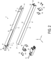
- FIG. 2 is an exploded perspective view illustrating an example of a fixing mechanism according to an embodiment.
- a fixing mechanism 2 includes the stationary frame 10, the rail 20, the first holding member 30, and the second holding member 40.
- the stationary frame 10 includes a top plate 11, a pair of side walls 12, a notch part 13, an engagement groove 14, a projection 15, an opening 16, and a plurality of self-tapping screws 19.
- the top plate 11 and the pair of side walls 12 of the stationary frame 10 are formed by bending a metal plate made of, for example, stainless steel.
- the pair of side walls 12 are continuous with the top plate 11 and oppose each other.
- the stationary frame 10 according to the present embodiment is fixed at the ceiling CL by the plurality of self-tapping screws 19, with the top plate 11 opposing the ceiling CL.
- the notch part 13 is an example of a second recess.
- the notch part 13 and the engagement groove 14 are formed symmetrically at each of the pair of side walls 12.
- the notch part 13 includes, at the pair of side walls 12, a part 17 cut out in the positive Y-axis direction from the end side at the negative Y-axis direction side, and a part 18 cut out at the negative X-axis direction side from the part 17.
- the notch part 13 is formed at the negative X-axis direction side from the center part at the X-axis of the pair of side walls 12, for example.
- the engagement groove 14 includes a part cut out in the negative X-axis direction from the end side of the positive X-axis direction side at the pair of side walls 12.
- the projection 15 and the opening 16 are formed at the top plate 11.
- the opening 16 is formed at a position close to the notch part 13 in the X-axis direction, for example.
- the projection 15 is formed continuously with the opening 16.
- the projection 15 is formed, for example, by cutting off a part corresponding to the opening 16 of the top plate 11, folding the part toward the negative Y-axis direction side, and then folding the part again toward the positive X-axis direction side.
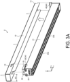
- FIGS. 3A and 3B are perspective views illustrating an example of a procedure for attaching the rail to the stationary frame according to the embodiment.
- the rail 20 includes a pair of side walls 21, a pair of feed rails 22a and 22b, a pair of first screw holes 23, a pair of second screw holes 24, the top plate 25, and end parts 27 and 28.
- the feed rails 22a and 22b correspond to, for example, one positive pole and the other negative pole.
- the pair of side walls 21 are continuous with the top plate 25 and oppose each other. In the present embodiment, the pair of side walls 21 and the top plate 25 are formed free from any unevenness, hole part, or the like.
- the pair of feed rails 22a and 22b are formed of a conductive magnetic body such as iron, for example.
- the pair of first screw holes 23 and the pair of second screw holes 24 are formed at the end parts 27 and 28 of the feed rails 22a and 22b, respectively.
- the pair of first screw holes 23 are formed at the end faces of the feed rails 22a and 22b at the negative X-axis direction side.
- the pair of second screw holes 24 are formed at the end faces of the feed rails 22a and 22b at the positive X-axis direction side.
- the first holding member 30 illustrated in FIG. 3A is fixed at the pair of first screw holes 23, and the second holding member 40 illustrated in FIG. 3A is fixed at the pair of second screw holes 24.
- the first holding member 30 is fixed at the pair of first screw holes 23 of the rail 20 by a pair of screws 39.
- an insulating sheet 38 is sandwiched between the first holding member 30 and the end face at the negative X-axis direction side of the rail 20.
- the second holding member 40 is fixed at the pair of second screw holes 24 of the rail 20 by a pair of screws 49.
- an insulating sheet 48 is sandwiched between the second holding member 40 and the end face of the rail 20 at the positive X-axis direction side.
- FIG. 4 is a perspective view illustrating an example of the first holding member according to an embodiment.
- the first holding member 30 includes a bottom surface 31, a pair of screw holes 32, a pair of projecting parts 33 and 34, and hole parts 35 and 36.
- the first holding member 30 is formed of a metal such as stainless steel, for example.
- the pair of screws 39 illustrated in FIG. 2 are inserted into the pair of screw holes 32 and fixed at the pair of first screw holes 23 of the rail 20.
- a hole part 35 is formed at the positive Y-axis direction side relative to the pair of screw holes 32, preferably at approximately the same position, in the Y-axis direction, as the pair of projecting parts 33 and 34.
- the projection 15 illustrated in FIG. 2 is inserted into the hole part 35.
- the feed part 50 illustrated in FIGS. 1 and 2 is inserted into a hole part 36.
- the feed part 50 receives power via a wiring line 51, for example.
- the feed part 50 also supplies power to the feed rails 22a and 22b by being connected to the feed rails 22a and 22b via the hole part 36.
- the feed part 50 is omitted.
- the pair of projecting parts 33 and 34 extend from the bottom surface 31 in the positive X-axis direction.
- the pair of projecting parts 33 and 34 are continuous with the bottom surface 31 and oppose each other in the Z-axis direction.
- the pair of projecting parts 33 and 34 are formed by bending a sheet of metal, for example. This causes the pair of projecting parts 33 and 34 to elastically deform in the direction of the arrow illustrated in FIG. 4 .
- the projecting part 33 further includes a pressing part 33a projecting in the negative Z-axis direction.
- the pressing part 33a is formed by further bending the projecting part 33, for example. In this case, it is desirable that the pressing part 33a is not deformed with respect to the projecting part 33.
- the projecting part 34 further includes a pressing part 34b projecting in the positive Z-axis direction.
- the pair of projecting parts 33 and 34 in the present embodiment are formed so that a width W2 in the Z-axis direction between the pair of projecting parts 33 and 34 illustrated in FIG. 4 is larger than a width W1 in the Z-axis direction of the stationary frame 10 illustrated in FIG. 3A .
- the pair of projecting parts 33 and 34 are deformed by applying force in the direction of the arrow illustrated in FIG. 4 to the pressing parts 33a and 34b.
- the width W2 is smaller than the width W1.
- the pressing parts 33a and 34b project outward in the Z-axis direction from the notch part 13 of the stationary frame 10.
- the pressing parts 33a and 34b act as hooks for the stationary frame 10, thereby suppressing movement of the stationary frame 10 in the positive X-axis direction. This suppresses the projection 15 of the stationary frame 10 from deviating from the hole part 35 of the first holding member 30.
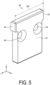
- FIG. 5 is a perspective view illustrating an example of the second holding member according to the embodiment.
- the second holding member 40 includes a main surface 41, a pair of screw holes 42, and a pair of projecting parts 43 and 44.
- the second holding member 40 is formed of a metal such as aluminum, for example.
- the rail 20 is mounted at the stationary frame 10 from the negative Y-axis direction side, as illustrated in FIGS. 3A and 3B .
- the rail 20 is mounted such that the pressing parts 33a and 34b of the first holding member 30 fixed at the rail 20 are inserted into the part 17 of the notch part 13 of the stationary frame 10.
- the pair of projecting parts 33 and 34 are deformed by a force applied in the direction of the arrow illustrated in FIG. 4 to the pressing parts 33a and 34b.
- the width W2 is smaller than the width W1.
- the projecting parts 43 and 44 of the second holding member 40 fixed at the rail 20 are located at the positive X-axis direction side from the end side at the positive X-axis direction side of the pair of side walls 12 of the stationary frame 10, as illustrated in FIG. 3B .
- the projecting part 44 of the second holding member 40 fixed at the rail 20 engages with the engagement groove 14 of the stationary frame 10, as illustrated in FIG. 6 .
- the main surface 41 of the second holding member 40 and the end side in the positive X-axis direction at the pair of side walls 12 of the stationary frame 10 are approximately flush.
- FIG. 7 is a top view illustrating an example of the stationary frame with the rail attached according to the embodiment.
- FIG. 8 is a cross-sectional view illustrating an example of the stationary frame with the rail attached according to the embodiment.
- FIG. 8 illustrates the cross section taken along line A-A in FIG. 7 .
- the rail 20 with the first holding member 30 and the second holding member 40 fixed is fixed at the stationary frame 10 by the projecting parts 33 and 34 and the pressing parts 33a and 34b of the first holding member 30 and the projecting parts 43 and 44 of the second holding member 40. Furthermore, the projection 15 of the stationary frame 10 is inserted into the hole part 35 of the first holding member 30. This firmly fixes the rail 20 to the stationary frame 10, preventing the rail 20 from wobbling or falling off.
- the rail 20 to be mounted with the first holding member 30 and the second holding member 40 need not be provided with unevenness or a hole portion for fixing at the stationary frame 10. As a result, the rail 20, the first holding member 30 and the second holding member 40 can easily be made the same color, thus improving the freedom of design and designability of the rail 20.
- the fixing mechanism 2 includes the rail 20 with an operation target 3 attached, the stationary frame 10 fixed at any of the wall surface, top surface or floor surface, and the holding members 30, 40 for holding the rail 20 at the stationary frame 10.
- the stationary frame 10 In the stationary frame 10, a second recess 13 engaging with the holding member 30 is formed in the first direction of the rail 20 extending.
- the holding member 30 is detachably fixed at the first end part 27 of the rail 20 in the first direction.
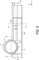
- FIG. 9 is a plan view illustrating an example of the lighting apparatus attached at the rail according to the embodiment.
- FIG. 9 illustrates the lighting system 1 in FIG. 1 as viewed from the negative Y-axis direction side.
- flange parts 26a and 26b extending from the pair of side walls 21 inward in the Z-axis direction are formed at the rail 20.
- FIG. 10 is a perspective view illustrating an example of the lighting apparatus according to the embodiment.
- FIG. 10 illustrates the lighting apparatus 3 as viewed from the positive Y-axis direction side, that is, the side attached at the rail 20.
- the housing 60 of the lighting apparatus 3 is formed of a resin, for example.
- the light body 71 of the lighting apparatus 3 is rotatably coupled to the housing 60 via the coupling part 79.
- the housing 60 includes a pair of feed magnets 61a and 61b, a backup magnet 62, screws 63a and 63b, hook parts 64a, 64b, 65a, 65b, and side walls 66a and 66b.
- a slider 90 is inserted into the housing 60 from the positive X-axis direction side.
- the feed magnets 61a and 61b are examples of a magnet.
- the pair of feed magnets 61a and 61b are attracted to the pair of feed rails 22a and 22b, respectively, with the lighting apparatus 3 attached at the rail 20.
- the pair of feed magnets 61a and 61b attract the housing 60 of the lighting apparatus 3 to the rail 20 and supply power from the feed rails 22a and 22b to the housing 60.
- the backup magnet 62 is attracted to the feed rail 22b but does not supply electricity from the feed rail 22b to the housing 60.
- the coil springs 81a and 81b illustrated in FIG. 10 are attached to the screws 63a and 63b.
- the hook parts 64a, 64b, 65a, and 65b are formed at the side walls 66a and 66b of the housing 60, respectively, and project outward in the Z-axis direction from the side walls 66a and 66b.
- the hook parts 64a, 64b, 65a and 65b extend in the Z-axis direction outward of the flange parts 26a and 26b of the rail 20 illustrated in FIG. 9 .
- the hook parts 64a, 64b, 65a and 65b prevent the lighting apparatus 3 from slipping out of the rail 20 when the lighting apparatus 3 is attached at the rail 20.
- the hook parts 64a, 64b, 65a and 65b have relatively higher elasticity compared to the side walls 66a and 66b. Thus, when the lighting apparatus 3 is attached at the rail 20, the hook parts 64a, 64b, 65a, 65b are elastically deformed inward in the Z-axis direction, so that the lighting apparatus 3 is attached at the rail 20.
- FIG. 11 is a perspective view illustrating an example of the slider according to the embodiment.
- projections 91a and 92a are formed at one end side (negative Z-axis direction side) in the Z-axis direction.
- the projections 91b and 92b are also formed at the opposite end side (positive Z-axis direction side) in the Z-axis direction of the slider 90.
- the projections 92a and 92b of the slider 90 fix the hook parts 65a and 65b from the inside in the Z-axis direction when the slider 90 is inserted into the housing 60.
- the projections 91a and 91b of the slider 90 fix the hook parts 64a and 64b from the inside in the Z-axis direction when the slider 90 is inserted into the housing 60.
- FIGS. 12A and 12B are enlarged perspective views illustrating an example of the hook part of the slider according to an embodiment.
- FIG. 12B illustrates the slider 90 fully inserted into the housing 60
- FIG. 12A illustrates the slider 90 partially pulled out in the positive X-axis direction.
- the position of the projection 91a of the slider 90 in the Z-axis direction is almost identical to the position of a face 64a1 on an inner side of the hook part 64a in the Z-axis direction.
- the projection 91a of the slider 90 is not in contact with the face 64a1 of the hook part 64a.
- the hook part 64a is elastically deformed inward in the Z-axis direction.
- FIG. 12B when the slider 90 is inserted into the housing 60, the projection 91a is in contact with the face 64a1 of the hook part 64a. This suppresses inward elastic deformation of the hook part 64a in the Z-axis direction.
- FIG. 13 is a cross-sectional view illustrating an example of the lighting apparatus attached at the rail according to the embodiment.
- FIG. 13 illustrates a cross section taken along line C-C in FIG. 9 .
- the hook part 64a of the housing 60 is located at the negative Z-axis direction side relative to the end part of the flange part 26a of the rail 20.
- the hook part 64b of the housing 60 is located at the positive Z-axis direction side relative to the end part of the flange part 26b of the rail 20.
- the hook parts 64a and 64b are fixed by the projections 91a and 91b of the slider 90, even upon application of an external force to the lighting apparatus 3 toward the negative Y-axis direction side, the hook parts 64a, 64b, 65a, and 65b are caught on the flange parts 26a and 26b, thereby preventing the lighting apparatus 3 from falling off the rail 20.
- the hook parts 64a and 64b can be elastically deformed by partially pulling the slider 90 out of the housing 60 as illustrated in FIG. 12A . This allows the lighting apparatus 3 to be easily removed from the rail 20.
- the malfunction of the lighting apparatus 3 is suppressed by providing, in addition to the feed magnets 61a and 61b, the conductive coil springs 81a and 81b at the housing 60 of the lighting apparatus 3.
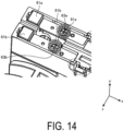
- FIG. 14 is an enlarged perspective view illustrating an example of the lighting apparatus according to the embodiment.
- FIG. 14 is an enlarged view of the portion illustrated in a frame F1 in FIG. 10 .
- the coil springs 81a and 81b are mounted at the screws 63a and 63b of the housing 60, respectively.
- the coil springs 81a and 81b are formed of a conductive metal such as copper, for example.
- the coil springs 81a and 81b energize the feed rails 22a and 22b in a direction (Y-axis direction) orthogonal to the feed rails 22a and 22b.
- the coil springs 81a and 81b are each an example of a conductive elastic body.
- FIG. 15 is a cross-sectional view illustrating an example of the lighting apparatus attached at the rail according to the embodiment.
- FIG. 15 illustrates the cross section taken along line B-B in FIG. 9 .
- FIG. 16A is an enlarged cross-sectional view illustrating an example of the lighting apparatus attached at the rail according to the embodiment.
- FIG. 16A is an enlarged view of the portion illustrated in a frame F2 in FIG. 15 .
- the housing 60 of the lighting apparatus 3 and the feed rail 22b are in contact with the coil spring 81b in addition to the feed magnet 61b and the backup magnet 62.
- the coil spring 81a like the coil spring 81b, also serves as a contact point with the feed rail 22a. In this case, the coil spring 81b is compressed in the negative Y-axis direction by the force of the feed magnet 61b and the backup magnet 62 being attracted to the feed rail 22b.
- FIG. 16B is an enlarged cross-sectional view illustrating an example of the lighting apparatus attached at the rail according to the embodiment.
- FIG. 16B illustrates an external force applied to the lighting apparatus 3 illustrated in FIG. 16A , tilting the housing 60 of the lighting apparatus 3 to the negative Y-axis direction and the positive X-axis direction.
- tilting of the housing 60 results in a gap G1 between the feed magnet 61b and the feed rail 22b, thereby impairing contact between the feed magnet 61b and the feed rail 22b at a part C0 in FIG. 16A .
- the lighting apparatus 3 may turn off or flash even when the backup magnet 62 is in contact with the feed rail 22b.
- contact between the coil spring 81b and the feed rail 22b at a part C1 in FIG. 16B is maintained by the force for the coil spring 81b compressed in the Y-axis direction to try to restore. This maintains the power supply to the housing 60, so that malfunction of the lighting apparatus 3 such as turning off or flashing is suppressed.
- an electronic apparatus 3 includes a magnet 61a attracted to the rail 22a and receiving power from the rail 22a, and a conductive elastic body 81a energizing the rail 22a in a first direction (Y-axis direction) orthogonal to the rail 22a.
- the conductive elastic body 81a is spaced apart from the magnet 61a in the second direction (positive X-axis direction) of the rail 22a extending, and is compressed in the first direction by the force of the magnet 61a being attracted to the rail 22a.
- the lighting apparatus 3 attached at the rail 20 can change the direction of illumination by, for example, changing the direction of the light body 71 of the lighting apparatus 3.
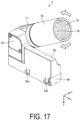
- the light body 71 of the lighting apparatus 3 is rotatably supported by the coupling part 79 as illustrated in FIG. 9 and FIG. 10 , and can be rotated from, for example, the direction illustrated in FIG. 9 and FIG. 10 (negative Y-axis direction) to the direction illustrated in FIG. 17 (negative Y-axis direction and positive X-axis direction).
- FIG. 17 is a perspective view illustrating an example of the lighting apparatus with the tubular part and the light body rotated according to the embodiment.
- the light body 71 can rotate from the positive X-axis direction side to the negative X-axis direction side with the coupling part 79 as the center.
- the tubular part 70 mounted at the light body 71 of the lighting apparatus 3 may be extended and contracted.
- an inner screw 78 is formed at the inner peripheral side.
- the position relative to the light body 71 is changed by turning the tubular part 70 in the peripheral direction (the direction indicated by the arrow in FIG. 17 ).
- the tubular part 70 may fall off from the light body 71.
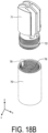
- FIGS. 18A and 18B are exploded perspective views of the tubular part according to the embodiment.
- the tubular part 70 of the lighting apparatus 3 according to the present embodiment is attached to the light body 71.
- the tubular part 70 is formed of a metal such as aluminum, for example.
- the light body 71 is formed of a metal such as aluminum, for example.
- a light source A2 for example, a light emitting diode (LED) is mounted at a substrate A1.
- the substrate A1 is placed at the light body 71.
- Inner screws 74 and 78 are formed at the inner peripheral surface of the tubular part 70.
- An outer screw 72 is formed at the outer peripheral surface of the light body 71.
- the outer screw 72 is screwed to the inner screw 78 formed at the tubular part 70 to fix the tubular part 70 to the light body 71.
- a first recess 75 constituting a lock mechanism B0 to be described later is further formed.
- the light body 71 is an example of a rotating body.
- FIG. 19 is a cross-sectional perspective view illustrating an example of the light body with a lock mechanism placed according to the embodiment.
- FIG. 19 illustrates the cross-sectional perspective view at a cross section S1 of the light body 71 in FIG. 18A .
- the parts illustrated by the broken lines in FIG. 19 correspond to a holder B1, a plate spring B2, a rocking shaft B3, a roller B4, a stopper B5 and a pressing part B6, constituting the lock mechanism B0.
- the lock mechanism B0 in the present embodiment includes the first recess 75 formed at the tubular part 70 and the holder B1 to the pressing part B6 arranged in the light body 71.
- the holder B1 to the pressing part B6 constituting the lock mechanism B0 are positioned near the opening 73 of the light body 71, as illustrated in FIG. 19 .
- the holder B1 holds the roller B4.
- the holder B1 is formed of a resin, for example.
- the plate spring B2 energizes the pressing part B6 outward in the radial direction of the light body 71. In the example illustrated in FIG. 19 , the plate spring B2 energizes the pressing part B6 in the negative Z-axis direction.
- the rocking shaft B3 fits into the light body 71, for example, and rockably supports the holder B1.
- the rocking shaft B3 is formed of a metal such as stainless steel, for example.
- the holder B1 is an example of a member holding a rotating member
- the plate spring B2 is an example of an energizing part.
- the roller B4 is exposed outward in the radial direction more than the outer screw 72 formed at the outer peripheral surface of the light body 71 through the opening 73.
- the roller B4 rotatably in contact with the inner peripheral surface of the tubular part 70.
- the roller B4 is pressed against the inner peripheral surface of the tubular part 70 by being energized by the pressing part B6.
- the roller B4 is formed, for example, of nickel-plated brass. Note that the roller B4 is an example of a rotating member.
- the stopper B5 serves as a detent of the tubular part 70 by being caught in the first recess 75 of the tubular part 70, as will be explained later.
- the pressing part B6 presses the holder B 1 holding the roller B4 outward in the radial direction by being energized by the plate spring B2.
- the wobble of the tubular part 70 is suppressed by the friction force generated between the roller B4 pressed outward in the radial direction and the inner screw 78 of the tubular part 70.
- the stopper B5 is an example of a protruding part.
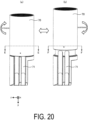
- FIG. 20 is a perspective view illustrating an example of extension and contraction of the tubular part according to the embodiment.
- FIG. 20(a) illustrates a state before the extension of the tubular part 70
- FIG. 20(b) illustrates a state after maximum extension of the tubular part 70.
- the rotation extending the tubular part 70 is not locked
- the rotation extending the tubular part 70 is locked.
- the positions illustrated in the cross section S1 of the light body 71 are approximately the same as the position illustrated in the cross section S1 of the light body 71 (the position illustrated in FIG. 19 ). That is, in the example illustrated in FIG. 20 , the position of the light body 71 illustrated in FIG. 20(b) has not changed from the position of the light body 71 illustrated in FIG. 20(a) , and only the position of the tubular part 70 in the Y-axis direction has changed.
- FIG. 21 is a cross-sectional view illustrating an example of the movement of a stopper according to an embodiment.
- FIG. 21(a) illustrates a cross section taken along line E-E in FIG. 20
- FIG. 21(b) illustrates a cross section taken along line F-F in FIG. 20 . That is, FIG. 21(a) illustrates the unlocked state of the rotation extending the tubular part 70, corresponding to FIG. 20(a)
- FIG. 21(b) illustrates the locked state of the rotation extending the tubular part 70, corresponding to FIG. 20(b) .
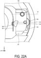
- FIGS. 22A and 22B are enlarged cross-sectional views illustrating an example of the movement of the stopper according to the embodiment.
- FIG. 22A is an enlarged view of the portion relating to the lock mechanism B0 in the unlocked state of the rotation extending the tubular part 70, that is, the portion indicated by the frame F3 in FIG. 21(a) .
- FIG. 22B is an enlarged view of the portion relating to the lock mechanism B0 in the locked state of the rotation extending the tubular part 70, that is, the portion indicated by the frame F4 in FIG. 21(b) .
- a position X1 of the rocking shaft B3 in the X-axis direction is located at the positive X-axis direction side relative to a center X4 in the X-axis direction of the holder B1 illustrated in FIG. 22A .
- a position X6 of the pressing part B6 in the X-axis direction is located at the negative X-axis direction side relative to the center X4 in the X-axis direction of the holder B1 illustrated in FIG. 22A .
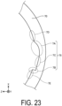
- FIG. 23 is an enlarged cross-sectional view illustrating an example of the tubular part according to the embodiment.
- FIG. 23 illustrates a cross section taken along line F-F in FIG. 20 .
- the first recess 75 formed at the inner peripheral surface of the tubular part 70 includes a curved part 7A and a step part 7B.
- the curved part 7A is an example of a first part
- the step part 7B is an example of a second part.
- the curved part 7A is formed so that an intermediate part 7C of the first recess 75, and a part 7D adjacent to the curved part 7A at the inner peripheral surface of the tubular part 70, are smoothly connected.
- the step part 7B is formed to discontinuously connect the intermediate part 7C of the first recess 75 and a part 7E adjacent to the step part 7B at the inner peripheral surface of the tubular part 70.
- the curved part 7A and the step part 7B are formed at opposite sides to each other in the peripheral direction, sandwiching the intermediate part 7C.
- the electronic apparatus 3 includes the rotating body 71 with the outer screw 72 formed at the outer peripheral surface, and the tubular part 70 with the inner screw 78 formed at the inner peripheral surface and screwed with the outer screw 72 of the rotating body 71.
- the opening 73 is formed at the outer peripheral surface of the rotating body 71.
- the rotating body 71 further includes the rotating member B4 exposed outward in the radial direction from the opening 73 and rotatably in contact with the inner peripheral surface of the tubular part 70.
- the first recess 75 suppressing rotation of the rotating member B4 is further formed at the inner peripheral surface of the tubular part 70. Such a configuration enables the tubular part to be stably held.
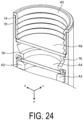
- FIG. 24 is a cross-sectional view illustrating an example of the tubular part according to the embodiment.
- FIG. 25 is an exploded perspective view illustrating an example of a cross section of the tubular part according to the embodiment.
- FIG. 24 illustrates a cross section taken along line D-D in FIG. 9 .
- a flange part 76 is further formed at the tubular part 70 according to the present embodiment.
- a lens A4 and a lens holder A3 are mounted at the tubular part 70. At the lens holder A3, for example, an outer screw is formed.
- the lens holder A3 is mounted at the tubular part 70 by being screwed into the inner screw 78 formed at the tubular part 70.
- the lens A4 is mounted at the tubular part 70 by being sandwiched between the lens holder A3 and the flange part 76 of the tubular part 70 in the Y-axis direction.
- a hood A5 and a filter A6 are further mounted at the tubular part 70 according to the present embodiment.
- the hood A5 for example, an outer screw is formed.
- the hood A5 is mounted at the tubular part 70 by being screwed into the inner screw 74 formed at the tubular part 70.
- the filter A6 is mounted at the tubular part 70 by being sandwiched between the flange part 76 of the tubular part 70 and the hood A5 in the Y-axis direction.
- FIG. 26 is a cross-sectional view illustrating an example of the tubular part with the filter removed according to the embodiment.
- the lens A4 is sandwiched between the lens holder A3 and the flange part 76, and the filter A6 is sandwiched between the flange part 76 and the hood A5, so that wobbling of a mounted lens, filter, or the like can be suppressed.
- the plate spring B2 of the lock mechanism B0 illustrated in FIG. 19 and FIG. 21 is an example of an elastic body energizing the pressing part B6 and can be achieved by another elastic member such as a coil spring or rubber. Further, a ball bearing or the like may be used instead of the roller B4.
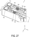
- FIG. 27 is an enlarged perspective view illustrating an example of a lighting apparatus including a plate spring according to the first modification.
- the lighting apparatus 4 according to the present modification differs from the lighting apparatus 3 illustrated in FIG. 14 in including plate springs 82a and 82b as illustrated in FIG. 27 in place of the coil springs 81a and 81b.
- the plate springs 82a and 82b are attached to the housing 60 by, for example, the screws 63a and 63b, respectively.
- the plate spring 82a includes a first projecting part 83a and a second projecting part 84a.
- the plate spring 82b includes a first projecting part 83b and a second projecting part 84b.
- the plate springs 82a and 82b are formed of a conductive metal such as copper, for example.
- FIG. 28 is an enlarged cross-sectional view illustrating an example of the lighting apparatus according to the first modification.
- FIG. 28 illustrates a cross section taken along line G-G in FIG. 27 .
- the first projecting part 83b and the second projecting part 84b of the plate spring 82b illustrated in FIG. 28 are compressed in the negative Y-axis direction by the force of the feed magnet 61b and the backup magnet 62 being attracted to the feed rail 22b, similar to the coil spring 81b.
- the first projecting part 83b and the second projecting part 84b project in the positive Y-axis direction with respect to the feed magnet 61b by a height H1 before the lighting apparatus 4 is attached to the rail 20.
- the first projecting part 83b and the second projecting part 84b are compressed such that the height in the positive Y-axis direction is approximately the same as the feed magnet 61b.
- the energizing force possessed by the coil springs 81a and 81b maintains contact between the lighting apparatus 3 and the feed rails 22a and 22b according to the embodiment.
- the energizing force when too large, affects the attraction force between the lighting apparatus 3 and the feed rail 22b by the feed magnet 61b and the backup magnet 62.
- the plate springs 82a and 82b as illustrated in FIG. 28 , the energizing force acting on the feed rails 22a and 22b can be easily adjusted appropriately.
- FIG. 29 is an enlarged perspective view illustrating an example of a lighting apparatus including a plate spring according to a second modification.
- a lighting apparatus 5 illustrated in FIG. 29 includes a plate spring 85a including a projecting part 86a and a plate spring 85b including a projecting part 86b.
- the projecting parts 86a and 86b may be alternately arranged in the X-axis direction.
- the energizing force required for the elastic body to maintain contact with the feed rail 22b depends on the distance between the feed magnet 61b and the elastic body.
- the larger a distance L1 between the feed magnet 61b and the second projecting part 84b of the plate spring 82b the smaller the energizing force required to maintain contact between the elastic body and the feed rail 22b.
- the larger the distance L1 the smaller the amount of displacement of each elastic body when the feed magnet 61a or 61b separates from the feed rail 22a or 22b.
- the component force of the energizing force of the elastic body to the feed magnet 61a and the backup magnet 62 also varies according to the distance L1.
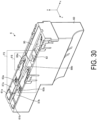
- FIG. 30 is a perspective view illustrating an example of a lighting apparatus according to a third modification.
- FIGS. 31A and 31B are enlarged perspective views illustrating examples of a plate spring according to the third modification.
- FIGS. 31A and FIG. 31B are enlarged views of the portion indicated by the frame F5 of FIG. 30 .
- FIG. 32 is a side view illustrating an example of the lighting apparatus according to the third modification.
- plate springs 87a and 87b in the present modification are also attached to the housing 60 by, for example, the screws 63a and 63b, respectively.
- the plate springs 87a and 87b are also formed of a conductive metal such as copper, for example.
- the plate springs 87a and 87b are formed to have lengths in the X-axis direction larger than the other plate springs illustrated in the other modifications.
- the plate springs 87a and 87b include projecting parts 88a and 88b, and tip parts 89a and 89b to be described below, respectively.
- a distance L2 from the feed magnet 61a to the projecting part 88a becomes larger than the distance in other embodiments and modifications, as illustrated in FIG. 32 .
- the distance L2 is preferably greater than 1/3 of the gap (magnet pitch) between the feed magnet 61b and the backup magnet 62 in the positive X-axis direction of a lighting apparatus 6, for example, to equalize the component forces of the feed magnet 61b and the backup magnet 62.
- the distance L2 be as close as possible to the length of the magnet pitch in the lighting apparatus 6, that is, the position of a projecting part 88a serving as the tip of the elastic body be closer to the backup magnet 62. This reduces the displacement amount of the tip of the projecting part 88a in the Y-axis direction, thereby reducing the load fluctuation at the contact portion between the projecting part 88a and the feed rail 22a or 22b.
- variation in the contact pressure of the projecting part 88a with respect to the feed rail 22a or 22b is also reduced, so that the margin for ensuring conduction at the feed magnet 61a or 61b can be increased.
- the projecting part 88a of the plate spring 87a illustrated in FIG. 32 is compressed in the negative Y-axis direction by the force of the feed magnet 61a being attracted to the feed rail 22a when the lighting apparatus 6 is attached to the rail 20.
- the projecting part 88a projects in the positive Y-axis direction by a height H2 with respect to the feed magnet 61a, as illustrated in FIG. 30 and FIG. 31A .
- the projecting part 88a is compressed such that the height in the positive Y-axis direction is approximately the same as the feed magnet 61a, as illustrated in FIG. 31B . That is, the plate spring 87a and the projecting part 88a change from the state of 87a2 and 88a2 to the state of 87a1 and 88a1.
- the height H2 between the feed magnet 61a and the projecting part 88a before the lighting apparatus 6 is attached to the rail 20 in the present modification is smaller than the height H1 between the feed magnet 61b and the projecting part 84b before the lighting apparatus 4 is attached to the rail 20 according to the first modification illustrated in FIG. 28 .
- the displacement amount of the projecting part 88a in the Y-axis direction can be reduced.
- FIG. 33A and FIG. 33B are perspective views illustrating an example of a slider according to the third modification. As illustrated in FIG. 33A and FIG. 33B , the slider 95 according to the present modification differs from the slider 90 according to the embodiment in including the openings 96a and 96b, moving parts 97a and 97b, and suppressing parts 98a and 98b.
- the moving part 97a of the slider 95 is formed to be movable in the X-axis direction.
- the moving part 97a clamps the projecting part 88a between the moving part 97a and the suppressing part 98a by moving in the positive X-axis direction.
- the suppressing part 98a comes into contact with the tip part 89a of the plate spring 87a from the positive Y-axis direction side.
- the suppressing part 98a suppresses the tip part 89a from deforming or moving in the positive Y-axis direction.
- the moving part 97b and the suppressing part 98b of the slider 95 are the same.
- FIG. 34A to FIG. 34C are enlarged perspective views illustrating an example of the positional relationship between the plate spring and the slider according to the third modification.
- the projecting part 88a of the plate spring 87a projects in the positive Y-axis direction from the opening 96a of the slider 95.
- the projecting part 88a changes from the state of 88a2 to the state of 88a1 as illustrated in FIG. 34B .
- the moving part 97a of the slider 95 moves in the positive X-axis direction
- the projecting part 88a is sandwiched between the moving part 97a and the suppressing part 98a of the slider 95, as illustrated in FIG. 34C .
- the tip part 89a of the plate spring 87a illustrated in FIG. 34B is suppressed from deforming or moving in the positive Y-axis direction by the suppressing part 98a of the slider 95.
- FIG. 36A is an enlarged perspective view illustrating an example of a lighting apparatus before the feed magnet is displaced according to the fourth modification.
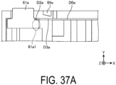
- FIG. 37A is a cross-sectional view illustrating an example of the displacement of a magnet according to the fourth modification.
- FIG. 36A is an enlarged view of the portion indicated by the frame F7 in FIG. 35 .
- FIG. 37A illustrates a cross section taken along line H-H in FIG. 36A .
- the suspension D0a includes an opening D1a, a tip part D2a, and a side face part D3a.
- the surface at the positive Y-axis direction side of a protruding part 61a1 of the feed magnet 61a is in contact with the tip part D2a of the suspension D0a.
- a limiter 69 suppressing displacement of the suspension D0a in the positive Y-axis direction is formed at the housing 60 according to the present modification.
- the feed magnet 61a is displaceable or rotatable in the Y-axis direction while maintaining contact with the housing 60. For example, even when the lighting apparatus 7 tilts or moves toward the negative Y-axis direction side, the position of the feed magnet 61a does not change due to the attraction force with respect to the feed rail 22a. That is, the feed magnet 61a is relatively displaced with respect to the lighting apparatus 7 when the lighting apparatus 7 tilts or moves.
- FIG. 36B is an enlarged perspective view illustrating an example of a lighting apparatus with the feed magnet displaced according to the fourth modification.
- FIG. 37B is a cross-sectional view illustrating an example of the displacement of the magnet according to the fourth modification.
- FIG. 37B illustrates a cross section taken along line I-I in FIG. 36B .
- the feed magnet 61a displaced in the positive Y-axis direction presses the suspension D0a in the positive Y-axis direction.
- the side face part D3a of the suspension D0a makes contact with the limiter 69, the displacement of the suspension D0a in the positive Y-axis direction is suppressed. This limits the displacement width and displacement angle of the feed magnet 61a pressing the suspension D0a.
- the suspension force can be adjusted by the shape of the suspension D0a, but also by adjusting the plate thickness of the suspension D0a.
- the number of parts of the housing 60 can be reduced.
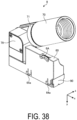
- FIG. 38 is a perspective view illustrating an example of a lighting apparatus according to a fifth modification. As illustrated in FIG. 38 , a lighting apparatus 8 according to the modification further includes a dial 6A.
- the stationary frame 10 may be attached at other objects, such as a floor or a wall surface.
- the tubular part 70 and the light body 71 may further include another lock mechanism to lock rotation in the direction shortening the tubular part 70, in addition to the lock mechanism B0.
- FIG. 10 illustrates a configuration of the electronic apparatus 3 including one backup magnet 62, but the electronic apparatus 3 may include no backup magnet, or may include two or more backup magnets.
Landscapes
- Engineering & Computer Science (AREA)
- General Engineering & Computer Science (AREA)
- Non-Portable Lighting Devices Or Systems Thereof (AREA)
- Casings For Electric Apparatus (AREA)
- Rotary Switch, Piano Key Switch, And Lever Switch (AREA)
- Pivots And Pivotal Connections (AREA)
Abstract
Description
- The present invention relates to an electronic apparatus and a fixing mechanism.
- In an electronic apparatus such as a lighting apparatus, a technique of changing the focal distance and irradiation shape of illumination is known. In this technique, a tubular part attached at the light body of the lighting apparatus is extended and contracted to adjust the focal distance and irradiation shape. When extending and contracting the tubular part, for example, an inner screw is formed at the tubular part and screwed into an outer screw formed at the light body so that the tubular part can be extended or shortened.
-
- Patent Document 1:
JP 4989394 B - Patent Document 2:
JP 3053783 UM-B - However, in a case where the tubular part is configured to extend and contract with respect to the light body, the tubular part may wobble relative to the light body or may fall off from the light body.
- An object of one aspect is to provide an electronic apparatus and a fixing mechanism to stably hold the tubular part.
- According to a first aspect of the present disclosure, there is provided an electronic apparatus comprising:
- a rotating body (71) having an outer screw (72) formed at an outer peripheral surface; and
- a tubular part (70) having an inner screw (78) formed at an inner peripheral surface, the inner screw (78) being screwed with the outer screw (72) of the rotating body (71),
- wherein
- an opening (73) is formed at the outer peripheral surface of the rotating body (71),
- the rotating body (71) further includes a rotating member (B4) exposed outward in a radial direction from the opening (73) and rotatably in contact with the inner peripheral surface of the tubular part (70), and
- a first recess (75) suppressing rotation of the rotating member (B4) is further formed at the inner peripheral surface of the tubular part (70).
- According to a second aspect of the present disclosure, there is provided the electronic apparatus (3, 4, 5, 6, 7, 8) according to the first aspect, wherein
the first recess (75) includes: - a first portion (7A) continuously connected with another portion (7D) of the inner peripheral surface; and
- a second portion (7B) located at a side opposite to the first portion (7A) in the peripheral direction and including a step formed between the second portion (7B) and another portion (7E) of the inner peripheral surface.
- According to a third aspect of the present disclosure, there is provided the electronic apparatus (3, 4, 5, 6, 7, 8) according to the second aspect, wherein
- the rotating body (71) further includes an energizing part (B2) configured to energize the rotating member (B4) outward in the radial direction, and
- the rotating member (B4) is pressed against the inner peripheral surface of the tubular part (70) by the energizing part (B2).
- According to a fourth aspect of the present disclosure, there is provided the electronic apparatus (3, 4, 5, 6, 7, 8) according to the third aspect, wherein
a member (B1) holding the rotating member (B4), when swung by the energizing part (B2), is rotatably supported in a manner that a portion (B5) opposing the second portion (7B) of the first recess (75) is further outward in the radial direction than a portion (B9) opposing the first portion (7A) of the first recess (75). - According to a fifth aspect of the present disclosure, there is provided the electronic apparatus (3, 4, 5, 6, 7, 8) according to any one of the second to fourth aspects, wherein
- the member (B1) holding the rotating member (B4) includes a protruding part (B5) projecting outward in the radial direction at the portion opposing the first portion (7A) of the first recess (75), and
- the rotation of the rotating member (B4) is suppressed by the protruding part (B5) being caught on the step formed at the second portion (7B).
- According to a sixth aspect of the present disclosure, there is provided the electronic apparatus (3, 4, 5, 6, 7, 8) according to any one of the first to fifth aspects, comprising:
- a magnet (61a, 61b) attracted to a rail (22a, 22b) and receiving power from the rail (22a, 22b); and
- a conductive elastic body (81a, 81b, 82a, 82b, 85a, 85b, 87a, 87b) energizing the rail (22a, 22b) in a first direction orthogonal to the rail (22a, 22b),
- wherein
- the conductive elastic body (81a, 81b, 82a, 82b, 85a, 85b, 87a, 87b) is placed at a position separated from the magnet (61a, 61b) in a second direction of the rail (22a, 22b) extending and is compressed in the first direction by a force of the magnet (61a, 61b) being attracted to the rail (22a, 22b).
- According to a seventh aspect of the present disclosure, there is provided the electronic apparatus (3, 4, 5, 6, 7, 8) according to the sixth aspect, wherein
the conductive elastic body (81a, 81b, 82a, 82b, 85a, 85b, 87a, 87b) is a plate spring (82a, 82b) or a coil spring (81a, 81b). - According to an eighth aspect of the present disclosure, there is provided the electronic apparatus (3, 4, 5, 6, 7, 8) according to the sixth or seventh aspect, wherein
the energizing force by the conductive elastic body (81a, 81b, 82a, 82b, 85a, 85b, 87a, 87b) to energize the rail (22a, 22b) in the first direction is smaller than the force of the magnet (61a, 61b) being attracted to the rail (22a, 22b). - According to a ninth aspect of the present disclosure, there is provided a fixing mechanism (2) comprising:
- a rail (22a, 22b) to be attached with the electronic apparatus (3, 4, 5, 6, 7, 8) according to any one of the first to eighth aspects;
- a stationary frame (10) fixed at any one of a wall surface, a top surface (CL) or a floor surface; and
- a holding member (30, 40) holding the rail (22a, 22b) at the stationary frame (10), wherein
- a second recess (13) engaging with the holding member (30, 40) is formed at the stationary frame (10) in a first direction of the rail (22a, 22b) extending, and
- the holding member (30, 40) is detachably fixed at an end part (27, 28) of the rail (22a, 22b) in the first direction.
- According to a tenth aspect of the present disclosure, there is provided the fixing mechanism (2) according to the ninth aspect, wherein
the holding member (30, 40) includes: - a first holding member (30) detachably fixed at a first end part (27) of the rail (22a, 22b) in the first direction and including a pair of projecting parts (33, 34) symmetrically formed in a second direction intersecting the first direction, the pair of projecting parts (33, 34) projecting in a direction from the first end part (27) to a second end part (28) in the first direction; and
- a second holding member (40) detachably fixed at the second end part (28) at a side opposite to the first end part (27) of the rail (22a, 22b) in the first direction and including a projection (43, 44) extending in the second direction.
- According to an eleventh aspect of the present disclosure, there is provided the fixing mechanism (2) according to the tenth aspect, wherein the first holding member (30) and the second holding member (40) are fixed at the rail (22a, 22b) by a screw (39, 49).
- According to a twelfth aspect of the present disclosure, there is provided the fixing mechanism (2) according to the tenth or eleventh aspect, wherein
- a gap (W2) of the pair of projecting parts (33, 34) in the second direction at the first holding member (30) is greater than a width (W1) of the stationary frame (10) in the second direction, and
- the pair of projecting parts (33, 34) elastically deform in the second direction.
- According to a thirteenth aspect of the present disclosure, there is provided the fixing mechanism (2) according to any one of the tenth to twelfth aspects, wherein
the second recess (13) includes: - a notch part (17) engaging with the pair of projecting parts (33, 34) of the first holding member (30); and
- an engagement part (14) engaging with the projection (43, 44) of the second holding member (40) formed at an end part (27, 28) of the stationary frame (10) in the first direction.
- According to a fourteenth aspect of the present disclosure, there is provided the fixing mechanism (2) according to any one of the tenth to thirteenth aspects, wherein
- a projecting part (15) projecting in the first direction in a direction from the first end part (27) to the second end part (28) is further formed at the stationary frame (10), and
- a hole part (35) accepting insertion of the projecting part (15) is further formed at the first holding member (30).
- According to one aspect, the tubular part can be stably held.
-
-
FIG. 1 illustrates an example of a lighting system according to an embodiment. -
FIG. 2 is an exploded perspective view illustrating an example of a fixing mechanism according to the embodiment. -
FIG. 3A is a perspective view illustrating an example of a procedure for attaching a rail to a stationary frame according to the embodiment. -
FIG. 3B is a perspective view illustrating an example of a procedure for attaching the rail to the stationary frame according to the embodiment. -
FIG. 4 is a perspective view illustrating an example of a first holding member according to the embodiment. -
FIG. 5 is a perspective view illustrating an example of a second holding member according to the embodiment. -
FIG. 6 is a perspective view illustrating an example of the stationary frame with the rail attached according to the embodiment. -
FIG. 7 is a top view illustrating an example of the stationary frame with the rail attached according to the embodiment. -
FIG. 8 is a cross-sectional view illustrating an example of the stationary frame with the rail attached according to the embodiment. -
FIG. 9 is a plan view illustrating an example of a lighting apparatus attached at the rail according to the embodiment. -
FIG. 10 is a perspective view illustrating an example of the lighting apparatus according to the embodiment. -
FIG. 11 is a perspective view illustrating an example of a slider according to the embodiment. -
FIG. 12A is an enlarged perspective view illustrating an example of a hook part of the slider according to the embodiment. -
FIG. 12B is an enlarged perspective view illustrating an example of the hook part of the slider according to the embodiment. -
FIG. 13 is a cross-sectional view illustrating an example of the lighting apparatus attached at the rail according to the embodiment. -
FIG. 14 is an enlarged perspective view illustrating an example of the lighting apparatus according to the embodiment. -
FIG. 15 is a cross-sectional view illustrating an example of the lighting apparatus attached at the rail according to the embodiment. -
FIG. 16A is an enlarged cross-sectional view illustrating an example of the lighting apparatus attached at the rail according to the embodiment. -
FIG. 16B is an enlarged cross-sectional view illustrating an example of the lighting apparatus attached at the rail according to the embodiment. -
FIG. 17 is a perspective view illustrating an example of the lighting apparatus with a tubular part and a light body according to the embodiment rotated. -
FIG. 18A is an exploded perspective view of the tubular part according to the embodiment. -
FIG. 18B is an exploded perspective view of the tubular part according to the embodiment. -
FIG. 19 is a cross-sectional perspective view illustrating an example of the light body with a lock mechanism arranged according to the embodiment. -
FIG. 20 is a perspective view illustrating an example of extension and contraction of the tubular part according to the embodiment. -
FIG. 21 is a cross-sectional view illustrating an example of movement of a stopper according to the embodiment. -
FIG. 22A is an enlarged cross-sectional view illustrating an example of movement of the stopper according to the embodiment. -
FIG. 22B is an enlarged cross-sectional view illustrating an example of movement of the stopper according to the embodiment. -
FIG. 23 is an enlarged cross-sectional view illustrating an example of the tubular part according to the embodiment. -
FIG. 24 is a cross-sectional view illustrating an example of the tubular part according to the embodiment. -
FIG. 25 is an exploded perspective view illustrating an example of a cross section of the tubular part according to the embodiment. -
FIG. 26 is a cross-sectional view illustrating an example of the tubular part with a filter according to the embodiment removed. -
FIG. 27 is an enlarged perspective view illustrating an example of the lighting apparatus including a plate spring according to a first modification. -
FIG. 28 is an enlarged cross-sectional view illustrating an example of the lighting apparatus according to the first modification. -
FIG. 29 is an enlarged perspective view illustrating an example of a lighting apparatus including a plate spring according to a second modification. -
FIG. 30 is a perspective view illustrating an example of a lighting apparatus according to a third modification. -
FIG. 31A is an enlarged perspective view illustrating an example of a plate spring according to the third modification. -
FIG. 31B is an enlarged perspective view illustrating an example of the plate spring according to the third modification. -
FIG. 32 is a side view illustrating an example of the lighting apparatus according to the third modification. -
FIG. 33A is a perspective view illustrating an example of a slider according to the third modification. -
FIG. 33B is a perspective view illustrating an example of the slider according to the third modification. -
FIG. 34A is an enlarged perspective view illustrating an example of the positional relationship between the plate spring and the slider according to the third modification. -
FIG. 34B is an enlarged perspective view illustrating an example of the positional relationship between the plate spring and the slider according to the third modification. -
FIG. 34C is an enlarged perspective view illustrating an example of the positional relationship between the plate spring and the slider according to the third modification. -
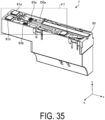
FIG. 35 is a perspective view illustrating an example of a lighting apparatus according to a fourth modification. -
FIG. 36A is an enlarged perspective view illustrating an example of a lighting apparatus before a feed magnet is displaced according to the fourth modification. -
FIG. 36B is an enlarged perspective view illustrating an example of the lighting apparatus after the feed magnet is displaced according to the fourth modification. -
FIG. 37A is a cross-sectional view illustrating an example of displacement of a magnet according to the fourth modification. -
FIG. 37B is a cross-sectional view illustrating an example of displacement of the magnet according to the fourth modification. -
FIG. 38 is a perspective view illustrating an example of a lighting apparatus according to a fifth modification. - The electronic apparatus and fixing mechanism disclosed in the present application are described in detail below with reference to the drawings. Note that the dimensional relationships between elements and the ratios of the elements in the drawings may differ from an actual configuration. The drawings may each include parts having mutually different dimensional relationships and proportions. In each drawing, a coordinate system is sometimes illustrated with the direction toward a ceiling CL to be described later as the positive Y-axis direction and the direction of a
rail 20 extending as the X-axis direction, for the sake of clarity. - First, a lighting system according to the present embodiment will be described with reference to
FIG. 1. FIG. 1 illustrates an example of a lighting system according to an embodiment. As illustrated inFIG. 1 , alighting system 1 according to the present embodiment includes astationary frame 10, therail 20, a first holdingmember 30, a second holdingmember 40, afeed part 50, and alighting apparatus 3. Thelighting apparatus 3 includes ahousing 60, atubular part 70, alight body 71, and acoupling part 79. As illustrated inFIG. 1 , an electronic apparatus to be operated, such as thelighting apparatus 3, is attached to therail 20. Thelight body 71 is an example of a rotating body. - The
stationary frame 10 is a member for fixing therail 20 to a ceiling, wall surface, floor surface, or the like. Therail 20 with the first holdingmember 30 and the second holdingmember 40 attached is fixed at thestationary frame 10, as illustrated inFIGS. 1 and2. FIG. 2 is an exploded perspective view illustrating an example of a fixing mechanism according to an embodiment. Hereafter, afixing mechanism 2 includes thestationary frame 10, therail 20, the first holdingmember 30, and the second holdingmember 40. - As illustrated in
FIG. 2 , thestationary frame 10 includes atop plate 11, a pair ofside walls 12, anotch part 13, anengagement groove 14, aprojection 15, anopening 16, and a plurality of self-tappingscrews 19. Thetop plate 11 and the pair ofside walls 12 of thestationary frame 10 are formed by bending a metal plate made of, for example, stainless steel. In this case, the pair ofside walls 12 are continuous with thetop plate 11 and oppose each other. Thestationary frame 10 according to the present embodiment is fixed at the ceiling CL by the plurality of self-tappingscrews 19, with thetop plate 11 opposing the ceiling CL. Note that thenotch part 13 is an example of a second recess. - The
notch part 13 and theengagement groove 14 are formed symmetrically at each of the pair ofside walls 12. Thenotch part 13 includes, at the pair ofside walls 12, apart 17 cut out in the positive Y-axis direction from the end side at the negative Y-axis direction side, and apart 18 cut out at the negative X-axis direction side from thepart 17. Thenotch part 13 is formed at the negative X-axis direction side from the center part at the X-axis of the pair ofside walls 12, for example. Theengagement groove 14 includes a part cut out in the negative X-axis direction from the end side of the positive X-axis direction side at the pair ofside walls 12. - The
projection 15 and theopening 16 are formed at thetop plate 11. Theopening 16 is formed at a position close to thenotch part 13 in the X-axis direction, for example. Theprojection 15 is formed continuously with theopening 16. Theprojection 15 is formed, for example, by cutting off a part corresponding to theopening 16 of thetop plate 11, folding the part toward the negative Y-axis direction side, and then folding the part again toward the positive X-axis direction side. -
FIGS. 3A and3B are perspective views illustrating an example of a procedure for attaching the rail to the stationary frame according to the embodiment. As illustrated inFIGS. 2 and3A , therail 20 includes a pair ofside walls 21, a pair offeed rails top plate 25, and endparts - The pair of
side walls 21 are continuous with thetop plate 25 and oppose each other. In the present embodiment, the pair ofside walls 21 and thetop plate 25 are formed free from any unevenness, hole part, or the like. The pair offeed rails - The pair of first screw holes 23 and the pair of second screw holes 24 are formed at the
end parts member 30 illustrated inFIG. 3A is fixed at the pair of first screw holes 23, and the second holdingmember 40 illustrated inFIG. 3A is fixed at the pair of second screw holes 24. - As illustrated in
FIG. 2 , the first holdingmember 30 is fixed at the pair of first screw holes 23 of therail 20 by a pair ofscrews 39. At this time, an insulatingsheet 38 is sandwiched between the first holdingmember 30 and the end face at the negative X-axis direction side of therail 20. The second holdingmember 40 is fixed at the pair of second screw holes 24 of therail 20 by a pair ofscrews 49. At this time, an insulatingsheet 48 is sandwiched between the second holdingmember 40 and the end face of therail 20 at the positive X-axis direction side. -
FIG. 4 is a perspective view illustrating an example of the first holding member according to an embodiment. The first holdingmember 30 includes abottom surface 31, a pair of screw holes 32, a pair of projectingparts hole parts member 30 is formed of a metal such as stainless steel, for example. - The pair of
screws 39 illustrated inFIG. 2 are inserted into the pair of screw holes 32 and fixed at the pair of first screw holes 23 of therail 20. Ahole part 35 is formed at the positive Y-axis direction side relative to the pair of screw holes 32, preferably at approximately the same position, in the Y-axis direction, as the pair of projectingparts projection 15 illustrated inFIG. 2 is inserted into thehole part 35. Thefeed part 50 illustrated inFIGS. 1 and2 is inserted into ahole part 36. Thefeed part 50 receives power via awiring line 51, for example. Thefeed part 50 also supplies power to the feed rails 22a and 22b by being connected to the feed rails 22a and 22b via thehole part 36. InFIG. 3A andFIG. 3B , thefeed part 50 is omitted. - The pair of projecting
parts bottom surface 31 in the positive X-axis direction. The pair of projectingparts bottom surface 31 and oppose each other in the Z-axis direction. The pair of projectingparts parts FIG. 4 . - Additionally, the projecting
part 33 further includes apressing part 33a projecting in the negative Z-axis direction. Thepressing part 33a is formed by further bending the projectingpart 33, for example. In this case, it is desirable that thepressing part 33a is not deformed with respect to the projectingpart 33. Similarly, the projectingpart 34 further includes apressing part 34b projecting in the positive Z-axis direction. - The pair of projecting
parts parts FIG. 4 is larger than a width W1 in the Z-axis direction of thestationary frame 10 illustrated inFIG. 3A . In this case, the pair of projectingparts FIG. 4 to thepressing parts FIG. 4 is lost, thepressing parts notch part 13 of thestationary frame 10. In this case, thepressing parts stationary frame 10, thereby suppressing movement of thestationary frame 10 in the positive X-axis direction. This suppresses theprojection 15 of thestationary frame 10 from deviating from thehole part 35 of the first holdingmember 30. -
FIG. 5 is a perspective view illustrating an example of the second holding member according to the embodiment. The second holdingmember 40 includes amain surface 41, a pair of screw holes 42, and a pair of projectingparts member 40 is formed of a metal such as aluminum, for example. - The pair of screw holes 42 are formed at the
main surface 41 of the second holdingmember 40. The pair ofscrews 49 illustrated inFIG. 2 are inserted into the pair of screw holes 42 and fixed at the pair of second screw holes 24 of therail 20. The pair of projectingparts main surface 41 of the second holdingmember 40. The pair of projectingparts parts FIG. 5 is larger than the width W1 in the Z-axis direction of thestationary frame 10 illustrated inFIG. 3A . - In the present embodiment, the
rail 20 is mounted at thestationary frame 10 from the negative Y-axis direction side, as illustrated inFIGS. 3A and3B . Therail 20 is mounted such that thepressing parts member 30 fixed at therail 20 are inserted into thepart 17 of thenotch part 13 of thestationary frame 10. - In this case, the pair of projecting
parts FIG. 4 to thepressing parts parts pressing parts side walls 12 of thestationary frame 10, as illustrated inFIG. 3B . - In addition, the projecting
parts member 40 fixed at therail 20 are located at the positive X-axis direction side from the end side at the positive X-axis direction side of the pair ofside walls 12 of thestationary frame 10, as illustrated inFIG. 3B . - The
rail 20, with the first holdingmember 30 and the second holdingmember 40 fixed, moves in the negative X-axis direction relative to thestationary frame 10 to be fixed at thestationary frame 10.FIG. 6 is a perspective view illustrating an example of the stationary frame with the rail attached according to the embodiment. While being attached at thestationary frame 10, thepressing part 34b of the first holdingmember 30 fixed at therail 20 moves from a position of thepart 17 of thestationary frame 10 illustrated inFIG. 3B to a position of thepart 18 of thestationary frame 10 illustrated inFIG. 6 . The other parts of the first holdingmember 30, including the projectingpart 34 but excluding thepressing part 34b, are not visible inFIG. 6 . - In addition, while being attached at the
stationary frame 10, the projectingpart 44 of the second holdingmember 40 fixed at therail 20 engages with theengagement groove 14 of thestationary frame 10, as illustrated inFIG. 6 . In this case, themain surface 41 of the second holdingmember 40 and the end side in the positive X-axis direction at the pair ofside walls 12 of thestationary frame 10 are approximately flush. - Additionally, the
hole part 35 of the first holdingmember 30 is inserted into theprojection 15 of thestationary frame 10 as illustrated inFIGS. 7 and8 .FIG. 7 is a top view illustrating an example of the stationary frame with the rail attached according to the embodiment.FIG. 8 is a cross-sectional view illustrating an example of the stationary frame with the rail attached according to the embodiment.FIG. 8 illustrates the cross section taken along line A-A inFIG. 7 . - When detaching the
rail 20 from thestationary frame 10, thepressing parts FIG. 7 are pressed in the direction of the arrow (Z-axis direction) illustrated inFIG. 4 and therail 20 is moved in the positive X-axis direction. Then, with therail 20 moved to the position illustrated inFIG. 3B , therail 20 can be removed from thestationary frame 10 by moving therail 20 in the negative Y-axis direction. - Thus, in the present embodiment, the
rail 20 with the first holdingmember 30 and the second holdingmember 40 fixed is fixed at thestationary frame 10 by the projectingparts pressing parts member 30 and the projectingparts member 40. Furthermore, theprojection 15 of thestationary frame 10 is inserted into thehole part 35 of the first holdingmember 30. This firmly fixes therail 20 to thestationary frame 10, preventing therail 20 from wobbling or falling off. Therail 20 to be mounted with the first holdingmember 30 and the second holdingmember 40 need not be provided with unevenness or a hole portion for fixing at thestationary frame 10. As a result, therail 20, the first holdingmember 30 and the second holdingmember 40 can easily be made the same color, thus improving the freedom of design and designability of therail 20. - As described above, the
fixing mechanism 2 according to the present embodiment includes therail 20 with anoperation target 3 attached, thestationary frame 10 fixed at any of the wall surface, top surface or floor surface, and the holdingmembers rail 20 at thestationary frame 10. In thestationary frame 10, asecond recess 13 engaging with the holdingmember 30 is formed in the first direction of therail 20 extending. The holdingmember 30 is detachably fixed at thefirst end part 27 of therail 20 in the first direction. With such a configuration, stability when therail 20 is fixed at thestationary frame 10 can be improved. - The
housing 60 of thelighting apparatus 3 illustrated inFIG. 1 is attached at therail 20 thus fixed at thestationary frame 10.FIG. 9 is a plan view illustrating an example of the lighting apparatus attached at the rail according to the embodiment.FIG. 9 illustrates thelighting system 1 inFIG. 1 as viewed from the negative Y-axis direction side. As illustrated inFIG. 9 ,flange parts side walls 21 inward in the Z-axis direction are formed at therail 20. -
FIG. 10 is a perspective view illustrating an example of the lighting apparatus according to the embodiment.FIG. 10 illustrates thelighting apparatus 3 as viewed from the positive Y-axis direction side, that is, the side attached at therail 20. Thehousing 60 of thelighting apparatus 3 is formed of a resin, for example. As illustrated inFIG. 10 , thelight body 71 of thelighting apparatus 3 is rotatably coupled to thehousing 60 via thecoupling part 79. In addition, thehousing 60 includes a pair offeed magnets backup magnet 62, screws 63a and 63b,hook parts side walls slider 90 is inserted into thehousing 60 from the positive X-axis direction side. Thefeed magnets - The pair of
feed magnets feed rails lighting apparatus 3 attached at therail 20. Thus, the pair offeed magnets housing 60 of thelighting apparatus 3 to therail 20 and supply power from the feed rails 22a and 22b to thehousing 60. Note that thebackup magnet 62 is attracted to thefeed rail 22b but does not supply electricity from thefeed rail 22b to thehousing 60. In addition, thecoil springs FIG. 10 are attached to thescrews - The
hook parts side walls housing 60, respectively, and project outward in the Z-axis direction from theside walls hook parts flange parts rail 20 illustrated inFIG. 9 . Thus, thehook parts lighting apparatus 3 from slipping out of therail 20 when thelighting apparatus 3 is attached at therail 20. - The
hook parts side walls lighting apparatus 3 is attached at therail 20, thehook parts lighting apparatus 3 is attached at therail 20. - Further, when the
slider 90 is inserted into thehousing 60, deformation of thehook parts slider 90. In this case, when thelighting apparatus 3 is shifted in the negative Y-axis direction, thehook parts flange parts rail 20, and thus thelighting apparatus 3 is less likely to fall off from therail 20. -
FIG. 11 is a perspective view illustrating an example of the slider according to the embodiment. As illustrated inFIG. 11 , in theslider 90,projections projections slider 90. Theprojections slider 90 fix thehook parts slider 90 is inserted into thehousing 60. Similarly, theprojections slider 90 fix thehook parts slider 90 is inserted into thehousing 60. -
FIGS. 12A and12B are enlarged perspective views illustrating an example of the hook part of the slider according to an embodiment.FIG. 12B illustrates theslider 90 fully inserted into thehousing 60, andFIG. 12A illustrates theslider 90 partially pulled out in the positive X-axis direction. As illustrated inFIGS. 12A and12B , the position of theprojection 91a of theslider 90 in the Z-axis direction is almost identical to the position of a face 64a1 on an inner side of thehook part 64a in the Z-axis direction. - In the state illustrated in
FIG. 12A , theprojection 91a of theslider 90 is not in contact with the face 64a1 of thehook part 64a. Thus, thehook part 64a is elastically deformed inward in the Z-axis direction. On the other hand, as illustrated inFIG. 12B , when theslider 90 is inserted into thehousing 60, theprojection 91a is in contact with the face 64a1 of thehook part 64a. This suppresses inward elastic deformation of thehook part 64a in the Z-axis direction. -
FIG. 13 is a cross-sectional view illustrating an example of the lighting apparatus attached at the rail according to the embodiment.FIG. 13 illustrates a cross section taken along line C-C inFIG. 9 . As illustrated inFIG. 13 , thehook part 64a of thehousing 60 is located at the negative Z-axis direction side relative to the end part of theflange part 26a of therail 20. Thehook part 64b of thehousing 60 is located at the positive Z-axis direction side relative to the end part of theflange part 26b of therail 20. That is, when thehook parts projections slider 90, even upon application of an external force to thelighting apparatus 3 toward the negative Y-axis direction side, thehook parts flange parts lighting apparatus 3 from falling off therail 20. When thelighting apparatus 3 is removed from therail 20, thehook parts slider 90 out of thehousing 60 as illustrated inFIG. 12A . This allows thelighting apparatus 3 to be easily removed from therail 20. - Even in a case where the
lighting apparatus 3 does not fall off from therail 20, once the connection between the feed rails 22a and 22b of therail 20 and thefeed magnets housing 60 is momentarily lost, malfunction such as thelighting apparatus 3 turning off or flashing may be occur. Thus, in the present embodiment, the malfunction of thelighting apparatus 3 is suppressed by providing, in addition to thefeed magnets conductive coil springs housing 60 of thelighting apparatus 3. -
FIG. 14 is an enlarged perspective view illustrating an example of the lighting apparatus according to the embodiment.FIG. 14 is an enlarged view of the portion illustrated in a frame F1 inFIG. 10 . As illustrated inFIG. 14 , thecoil springs screws housing 60, respectively. The coil springs 81a and 81b are formed of a conductive metal such as copper, for example. The coil springs 81a and 81b energize the feed rails 22a and 22b in a direction (Y-axis direction) orthogonal to the feed rails 22a and 22b. The coil springs 81a and 81b are each an example of a conductive elastic body. -
FIG. 15 is a cross-sectional view illustrating an example of the lighting apparatus attached at the rail according to the embodiment.FIG. 15 illustrates the cross section taken along line B-B inFIG. 9 .FIG. 16A is an enlarged cross-sectional view illustrating an example of the lighting apparatus attached at the rail according to the embodiment.FIG. 16A is an enlarged view of the portion illustrated in a frame F2 inFIG. 15 . As illustrated inFIG. 15 andFIG. 16A , thehousing 60 of thelighting apparatus 3 and thefeed rail 22b are in contact with thecoil spring 81b in addition to thefeed magnet 61b and thebackup magnet 62. Thecoil spring 81a, like thecoil spring 81b, also serves as a contact point with thefeed rail 22a. In this case, thecoil spring 81b is compressed in the negative Y-axis direction by the force of thefeed magnet 61b and thebackup magnet 62 being attracted to thefeed rail 22b. -
FIG. 16B is an enlarged cross-sectional view illustrating an example of the lighting apparatus attached at the rail according to the embodiment.FIG. 16B illustrates an external force applied to thelighting apparatus 3 illustrated inFIG. 16A , tilting thehousing 60 of thelighting apparatus 3 to the negative Y-axis direction and the positive X-axis direction. In the example illustrated inFIG. 16B , tilting of thehousing 60 results in a gap G1 between thefeed magnet 61b and thefeed rail 22b, thereby impairing contact between thefeed magnet 61b and thefeed rail 22b at a part C0 inFIG. 16A . In this case, thelighting apparatus 3 may turn off or flash even when thebackup magnet 62 is in contact with thefeed rail 22b. However, in the present embodiment, contact between thecoil spring 81b and thefeed rail 22b at a part C1 inFIG. 16B is maintained by the force for thecoil spring 81b compressed in the Y-axis direction to try to restore. This maintains the power supply to thehousing 60, so that malfunction of thelighting apparatus 3 such as turning off or flashing is suppressed. - As described above, an
electronic apparatus 3 according to the present embodiment includes amagnet 61a attracted to therail 22a and receiving power from therail 22a, and a conductiveelastic body 81a energizing therail 22a in a first direction (Y-axis direction) orthogonal to therail 22a. The conductiveelastic body 81a is spaced apart from themagnet 61a in the second direction (positive X-axis direction) of therail 22a extending, and is compressed in the first direction by the force of themagnet 61a being attracted to therail 22a. Such a configuration enables a stable power supply to theelectronic apparatus 3 to be maintained. - The
lighting apparatus 3 attached at therail 20 can change the direction of illumination by, for example, changing the direction of thelight body 71 of thelighting apparatus 3. In the present embodiment, thelight body 71 of thelighting apparatus 3 is rotatably supported by thecoupling part 79 as illustrated inFIG. 9 andFIG. 10 , and can be rotated from, for example, the direction illustrated inFIG. 9 andFIG. 10 (negative Y-axis direction) to the direction illustrated inFIG. 17 (negative Y-axis direction and positive X-axis direction).FIG. 17 is a perspective view illustrating an example of the lighting apparatus with the tubular part and the light body rotated according to the embodiment. In the examples illustrated inFIG. 9 ,FIG. 10 andFIG. 17 , thelight body 71 can rotate from the positive X-axis direction side to the negative X-axis direction side with thecoupling part 79 as the center. - Further, to control the light distribution, the
tubular part 70 mounted at thelight body 71 of thelighting apparatus 3 may be extended and contracted. In thetubular part 70, for example, aninner screw 78 is formed at the inner peripheral side. In this case, the position relative to thelight body 71 is changed by turning thetubular part 70 in the peripheral direction (the direction indicated by the arrow inFIG. 17 ). In this case, when thetubular part 70 rotates in the extending direction, thetubular part 70 may fall off from thelight body 71. - Thus, the
tubular part 70 and thelight body 71 of thelighting apparatus 3 according to the present embodiment includes a lock mechanism for limiting the range of turning thetubular part 70 in the direction of extending and contracting.FIGS. 18A and18B are exploded perspective views of the tubular part according to the embodiment. As illustrated inFIG. 18A , thetubular part 70 of thelighting apparatus 3 according to the present embodiment is attached to thelight body 71. Thetubular part 70 is formed of a metal such as aluminum, for example. Thelight body 71 is formed of a metal such as aluminum, for example. In the present embodiment, a light source A2, for example, a light emitting diode (LED) is mounted at a substrate A1. The substrate A1 is placed at thelight body 71. -
Inner screws tubular part 70. Anouter screw 72 is formed at the outer peripheral surface of thelight body 71. Theouter screw 72 is screwed to theinner screw 78 formed at thetubular part 70 to fix thetubular part 70 to thelight body 71. Additionally, as illustrated inFIG. 18B , at the inner peripheral surface forming theinner screw 78 of thetubular part 70, afirst recess 75 constituting a lock mechanism B0 to be described later is further formed. Note that thelight body 71 is an example of a rotating body. - In addition, an
opening 73 is formed at the outer peripheral part of thelight body 71 including theouter screw 72, as illustrated inFIG. 19. FIG. 19 is a cross-sectional perspective view illustrating an example of the light body with a lock mechanism placed according to the embodiment.FIG. 19 illustrates the cross-sectional perspective view at a cross section S1 of thelight body 71 inFIG. 18A . The parts illustrated by the broken lines inFIG. 19 correspond to a holder B1, a plate spring B2, a rocking shaft B3, a roller B4, a stopper B5 and a pressing part B6, constituting the lock mechanism B0. The lock mechanism B0 in the present embodiment includes thefirst recess 75 formed at thetubular part 70 and the holder B1 to the pressing part B6 arranged in thelight body 71. In the present embodiment, the holder B1 to the pressing part B6 constituting the lock mechanism B0 are positioned near theopening 73 of thelight body 71, as illustrated inFIG. 19 . - The holder B1 holds the roller B4. The holder B1 is formed of a resin, for example. The plate spring B2 energizes the pressing part B6 outward in the radial direction of the
light body 71. In the example illustrated inFIG. 19 , the plate spring B2 energizes the pressing part B6 in the negative Z-axis direction. The rocking shaft B3 fits into thelight body 71, for example, and rockably supports the holder B1. The rocking shaft B3 is formed of a metal such as stainless steel, for example. Note that the holder B1 is an example of a member holding a rotating member, and the plate spring B2 is an example of an energizing part. - The roller B4 is exposed outward in the radial direction more than the
outer screw 72 formed at the outer peripheral surface of thelight body 71 through theopening 73. The roller B4 rotatably in contact with the inner peripheral surface of thetubular part 70. In the present embodiment, the roller B4 is pressed against the inner peripheral surface of thetubular part 70 by being energized by the pressing part B6. The roller B4 is formed, for example, of nickel-plated brass. Note that the roller B4 is an example of a rotating member. - The stopper B5 serves as a detent of the
tubular part 70 by being caught in thefirst recess 75 of thetubular part 70, as will be explained later. The pressing part B6 presses theholder B 1 holding the roller B4 outward in the radial direction by being energized by the plate spring B2. The wobble of thetubular part 70 is suppressed by the friction force generated between the roller B4 pressed outward in the radial direction and theinner screw 78 of thetubular part 70. The stopper B5 is an example of a protruding part. -
FIG. 20 is a perspective view illustrating an example of extension and contraction of the tubular part according to the embodiment.FIG. 20(a) illustrates a state before the extension of thetubular part 70, andFIG. 20(b) illustrates a state after maximum extension of thetubular part 70. In the state illustrated inFIG. 20(a) , the rotation extending thetubular part 70 is not locked, and in the state illustrated inFIG. 20(b) , the rotation extending thetubular part 70 is locked. In addition, in the Y-axis direction, the position of thelight body 71 at the E-E line inFIG. 20(a) and the position of thelight body 71 at the F-F line inFIG. 20(b) are approximately the same as the position illustrated in the cross section S1 of the light body 71 (the position illustrated inFIG. 19 ). That is, in the example illustrated inFIG. 20 , the position of thelight body 71 illustrated inFIG. 20(b) has not changed from the position of thelight body 71 illustrated inFIG. 20(a) , and only the position of thetubular part 70 in the Y-axis direction has changed. -
FIG. 21 is a cross-sectional view illustrating an example of the movement of a stopper according to an embodiment.FIG. 21(a) illustrates a cross section taken along line E-E inFIG. 20 , andFIG. 21(b) illustrates a cross section taken along line F-F inFIG. 20 . That is,FIG. 21(a) illustrates the unlocked state of the rotation extending thetubular part 70, corresponding toFIG. 20(a) , andFIG. 21(b) illustrates the locked state of the rotation extending thetubular part 70, corresponding toFIG. 20(b) . -
FIGS. 22A and22B are enlarged cross-sectional views illustrating an example of the movement of the stopper according to the embodiment.FIG. 22A is an enlarged view of the portion relating to the lock mechanism B0 in the unlocked state of the rotation extending thetubular part 70, that is, the portion indicated by the frame F3 inFIG. 21(a) .FIG. 22B is an enlarged view of the portion relating to the lock mechanism B0 in the locked state of the rotation extending thetubular part 70, that is, the portion indicated by the frame F4 inFIG. 21(b) . - As illustrated in
FIG. 22A , in the present embodiment, a position X1 of the rocking shaft B3 in the X-axis direction is located at the positive X-axis direction side relative to a center X4 in the X-axis direction of the holder B1 illustrated inFIG. 22A . On the other hand, a position X6 of the pressing part B6 in the X-axis direction is located at the negative X-axis direction side relative to the center X4 in the X-axis direction of the holder B1 illustrated inFIG. 22A . In this case, when the pressing part B6 is pressed by the plate spring B2, the holder B1 swings in the direction indicated by the arrow R1 with the rocking shaft B3 as the center, as illustrated inFIG. 22B . Consequently, as illustrated inFIG. 22B , a corner B9 of the holder B1 swings in the direction indicated by the arrow V2 (positive Z-axis direction), while the stopper B5 swings in the direction indicated by the arrow V1 (negative Z-axis direction). As illustrated inFIG. 22A , for example, the roller B4 is positioned near the center X4 in the X-axis direction of the holder B1. -
FIG. 23 is an enlarged cross-sectional view illustrating an example of the tubular part according to the embodiment.FIG. 23 illustrates a cross section taken along line F-F inFIG. 20 . As illustrated inFIG. 23 , thefirst recess 75 formed at the inner peripheral surface of thetubular part 70 includes acurved part 7A and astep part 7B. Note that thecurved part 7A is an example of a first part and thestep part 7B is an example of a second part. - The
curved part 7A is formed so that anintermediate part 7C of thefirst recess 75, and apart 7D adjacent to thecurved part 7A at the inner peripheral surface of thetubular part 70, are smoothly connected. On the other hand, thestep part 7B is formed to discontinuously connect theintermediate part 7C of thefirst recess 75 and apart 7E adjacent to thestep part 7B at the inner peripheral surface of thetubular part 70. Thecurved part 7A and thestep part 7B are formed at opposite sides to each other in the peripheral direction, sandwiching theintermediate part 7C. - In this case, when the roller B4 rotates in the direction indicated by an arrow R3, the
tubular part 70 rotates smoothly with respect to thelight body 71 because the corner B9 swinging in the direction indicated by the arrow V2 inFIG. 22B does not make contact with thecurved part 7A of thetubular part 70 or theadjacent part 7D. On the other hand, when the roller B4 rotates in the direction indicated by an arrow R2, the stopper B5 swinging in the direction indicated by the arrow V1 is caught on thestep part 7B of thefirst recess 75, and thus rotation of thetubular part 70 with respect to thelight body 71 is suppressed. That is, the lock mechanism B0 including thefirst recess 75 and the roller B4 serves as a detent for thetubular part 70. - As described above, the
electronic apparatus 3 according to the present embodiment includes therotating body 71 with theouter screw 72 formed at the outer peripheral surface, and thetubular part 70 with theinner screw 78 formed at the inner peripheral surface and screwed with theouter screw 72 of therotating body 71. Theopening 73 is formed at the outer peripheral surface of therotating body 71. The rotatingbody 71 further includes the rotating member B4 exposed outward in the radial direction from theopening 73 and rotatably in contact with the inner peripheral surface of thetubular part 70. Thefirst recess 75 suppressing rotation of the rotating member B4 is further formed at the inner peripheral surface of thetubular part 70. Such a configuration enables the tubular part to be stably held. - Further, control of light distribution by the
lighting apparatus 3 can be achieved by attaching a lens or a filter to thetubular part 70 or thelight body 71.FIG. 24 is a cross-sectional view illustrating an example of the tubular part according to the embodiment.FIG. 25 is an exploded perspective view illustrating an example of a cross section of the tubular part according to the embodiment.FIG. 24 illustrates a cross section taken along line D-D inFIG. 9 . As illustrated inFIG. 24 andFIG. 25 , aflange part 76 is further formed at thetubular part 70 according to the present embodiment. Additionally, a lens A4 and a lens holder A3 are mounted at thetubular part 70. At the lens holder A3, for example, an outer screw is formed. In this case, the lens holder A3 is mounted at thetubular part 70 by being screwed into theinner screw 78 formed at thetubular part 70. In the present embodiment, the lens A4 is mounted at thetubular part 70 by being sandwiched between the lens holder A3 and theflange part 76 of thetubular part 70 in the Y-axis direction. - In addition, as illustrated in
FIG. 24 andFIG. 25 , a hood A5 and a filter A6 are further mounted at thetubular part 70 according to the present embodiment. At the hood A5, for example, an outer screw is formed. In this case, the hood A5 is mounted at thetubular part 70 by being screwed into theinner screw 74 formed at thetubular part 70. In the present embodiment, the filter A6 is mounted at thetubular part 70 by being sandwiched between theflange part 76 of thetubular part 70 and the hood A5 in the Y-axis direction. - According to the configuration described above, the lens or filter used for controlling the light distribution of the
lighting apparatus 3 can be easily attached to and detached from thelighting apparatus 3. For example, when replacing or removing the filter A6, the hood A5 screw-locked to thetubular part 70 is only required to be removed as illustrated in the exploded view ofFIG. 25 .FIG. 26 is a cross-sectional view illustrating an example of the tubular part with the filter removed according to the embodiment. According to such a configuration, the lens A4 is sandwiched between the lens holder A3 and theflange part 76, and the filter A6 is sandwiched between theflange part 76 and the hood A5, so that wobbling of a mounted lens, filter, or the like can be suppressed. - The configurations of the present embodiment have been described above, but the embodiment is not limited to these configurations. For example, the plate spring B2 of the lock mechanism B0 illustrated in
FIG. 19 andFIG. 21 is an example of an elastic body energizing the pressing part B6 and can be achieved by another elastic member such as a coil spring or rubber. Further, a ball bearing or the like may be used instead of the roller B4. - Additionally, the elastic body used in the configuration to maintain the power supply, as described with reference to
FIGS. 14 to 16B , is not limited to thecoil springs FIG. 14 . For example, a conductive plate spring may be used as the elastic body.FIG. 27 is an enlarged perspective view illustrating an example of a lighting apparatus including a plate spring according to the first modification. Thelighting apparatus 4 according to the present modification differs from thelighting apparatus 3 illustrated inFIG. 14 in including plate springs 82a and 82b as illustrated inFIG. 27 in place of thecoil springs - As illustrated in
FIG. 27 , the plate springs 82a and 82b are attached to thehousing 60 by, for example, thescrews plate spring 82a includes a first projectingpart 83a and a second projectingpart 84a. Similarly, theplate spring 82b includes a first projectingpart 83b and a second projectingpart 84b. The plate springs 82a and 82b are formed of a conductive metal such as copper, for example. - The plate springs 82a and 82b, similar to the
coil springs FIG. 28 is an enlarged cross-sectional view illustrating an example of the lighting apparatus according to the first modification.FIG. 28 illustrates a cross section taken along line G-G inFIG. 27 . When thelighting apparatus 4 is attached to therail 20, the first projectingpart 83b and the second projectingpart 84b of theplate spring 82b illustrated inFIG. 28 are compressed in the negative Y-axis direction by the force of thefeed magnet 61b and thebackup magnet 62 being attracted to thefeed rail 22b, similar to thecoil spring 81b. For example, the first projectingpart 83b and the second projectingpart 84b project in the positive Y-axis direction with respect to thefeed magnet 61b by a height H1 before thelighting apparatus 4 is attached to therail 20. However, after thelighting apparatus 4 is attached to therail 20, the first projectingpart 83b and the second projectingpart 84b are compressed such that the height in the positive Y-axis direction is approximately the same as thefeed magnet 61b. - As illustrated in
FIGS. 14 to 16B , the energizing force possessed by thecoil springs lighting apparatus 3 and the feed rails 22a and 22b according to the embodiment. However, the energizing force, when too large, affects the attraction force between thelighting apparatus 3 and thefeed rail 22b by thefeed magnet 61b and thebackup magnet 62. Thus, in the present modification, by using the plate springs 82a and 82b as illustrated inFIG. 28 , the energizing force acting on the feed rails 22a and 22b can be easily adjusted appropriately. - Further, in
FIG. 28 , the configuration including theplate spring 82b having two projectingparts FIG. 29 is an enlarged perspective view illustrating an example of a lighting apparatus including a plate spring according to a second modification. Alighting apparatus 5 illustrated inFIG. 29 includes aplate spring 85a including a projectingpart 86a and aplate spring 85b including a projectingpart 86b. As illustrated inFIG. 29 , the projectingparts - Additionally, as illustrated in
FIG. 16B , when contact between thefeed magnet 61b and thefeed rail 22b is impaired, the energizing force required for the elastic body to maintain contact with thefeed rail 22b depends on the distance between thefeed magnet 61b and the elastic body. For example, as illustrated inFIG. 28 , the larger a distance L1 between thefeed magnet 61b and the second projectingpart 84b of theplate spring 82b, the smaller the energizing force required to maintain contact between the elastic body and thefeed rail 22b. The larger the distance L1, the smaller the amount of displacement of each elastic body when thefeed magnet feed rail feed magnet 61a and thebackup magnet 62 also varies according to the distance L1. - Thus, as illustrated in
FIG. 30 and below, a plate spring with a longer distance from thefeed magnet 61b to the projecting part may be used.FIG. 30 is a perspective view illustrating an example of a lighting apparatus according to a third modification.FIGS. 31A and31B are enlarged perspective views illustrating examples of a plate spring according to the third modification.FIGS. 31A andFIG. 31B are enlarged views of the portion indicated by the frame F5 ofFIG. 30 .FIG. 32 is a side view illustrating an example of the lighting apparatus according to the third modification. As illustrated inFIG. 30 , plate springs 87a and 87b in the present modification are also attached to thehousing 60 by, for example, thescrews - The plate springs 87a and 87b are formed to have lengths in the X-axis direction larger than the other plate springs illustrated in the other modifications. The plate springs 87a and 87b include projecting
parts tip parts 89a and 89b to be described below, respectively. In the present modification, a distance L2 from thefeed magnet 61a to the projectingpart 88a becomes larger than the distance in other embodiments and modifications, as illustrated inFIG. 32 . In the present modification, the distance L2 is preferably greater than 1/3 of the gap (magnet pitch) between thefeed magnet 61b and thebackup magnet 62 in the positive X-axis direction of alighting apparatus 6, for example, to equalize the component forces of thefeed magnet 61b and thebackup magnet 62. In addition, it is preferable that the distance L2 be as close as possible to the length of the magnet pitch in thelighting apparatus 6, that is, the position of a projectingpart 88a serving as the tip of the elastic body be closer to thebackup magnet 62. This reduces the displacement amount of the tip of the projectingpart 88a in the Y-axis direction, thereby reducing the load fluctuation at the contact portion between the projectingpart 88a and thefeed rail part 88a with respect to thefeed rail feed magnet - The projecting
part 88a of theplate spring 87a illustrated inFIG. 32 , like other modifications, is compressed in the negative Y-axis direction by the force of thefeed magnet 61a being attracted to thefeed rail 22a when thelighting apparatus 6 is attached to therail 20. For example, before thelighting apparatus 6 is attached to therail 20, the projectingpart 88a projects in the positive Y-axis direction by a height H2 with respect to thefeed magnet 61a, as illustrated inFIG. 30 andFIG. 31A . Then, after thelighting apparatus 6 is attached to therail 20, the projectingpart 88a is compressed such that the height in the positive Y-axis direction is approximately the same as thefeed magnet 61a, as illustrated inFIG. 31B . That is, theplate spring 87a and the projectingpart 88a change from the state of 87a2 and 88a2 to the state of 87a1 and 88a1. - As illustrated in
FIG. 32 , the height H2 between thefeed magnet 61a and the projectingpart 88a before thelighting apparatus 6 is attached to therail 20 in the present modification is smaller than the height H1 between thefeed magnet 61b and the projectingpart 84b before thelighting apparatus 4 is attached to therail 20 according to the first modification illustrated inFIG. 28 . Thus, by increasing the distance L2 between thefeed magnet 61a and the projectingpart 88a, the displacement amount of the projectingpart 88a in the Y-axis direction can be reduced. - The projecting
part 88a of theplate spring 87a projects in the negative Y-axis direction, for example, from anopening 96a formed at aslider 95 illustrated inFIG. 33A andFIG. 33B . In the present modification, thetip part 89a of theplate spring 87a may come into contact with theslider 95 in the Y-axis direction.FIG. 33A andFIG. 33B are perspective views illustrating an example of a slider according to the third modification. As illustrated inFIG. 33A andFIG. 33B , theslider 95 according to the present modification differs from theslider 90 according to the embodiment in including theopenings parts parts - The moving
part 97a of theslider 95 is formed to be movable in the X-axis direction. When the projectingpart 88a of theplate spring 87a projects from theopening 96a, the movingpart 97a clamps the projectingpart 88a between the movingpart 97a and the suppressingpart 98a by moving in the positive X-axis direction. In this case, the suppressingpart 98a comes into contact with thetip part 89a of theplate spring 87a from the positive Y-axis direction side. Thus, the suppressingpart 98a suppresses thetip part 89a from deforming or moving in the positive Y-axis direction. The same is true for the movingpart 97b and the suppressingpart 98b of theslider 95. -
FIG. 34A to FIG. 34C are enlarged perspective views illustrating an example of the positional relationship between the plate spring and the slider according to the third modification. As illustrated inFIG. 34A , the projectingpart 88a of theplate spring 87a projects in the positive Y-axis direction from theopening 96a of theslider 95. Then, by compression in the negative Y-axis direction, the projectingpart 88a changes from the state of 88a2 to the state of 88a1 as illustrated inFIG. 34B . Then, when the movingpart 97a of theslider 95 moves in the positive X-axis direction, the projectingpart 88a is sandwiched between the movingpart 97a and the suppressingpart 98a of theslider 95, as illustrated inFIG. 34C . In this case, thetip part 89a of theplate spring 87a illustrated inFIG. 34B is suppressed from deforming or moving in the positive Y-axis direction by the suppressingpart 98a of theslider 95. - Thus, in the present modification, even when a force in the positive Y-axis direction (force to remove the
plate spring 87a from the housing 60) is applied to theplate spring 87a, the deformation of theplate spring 87a and the projectingpart 88a in the negative Y-axis direction is suppressed. - In the above embodiment and each modification, a configuration using a conductive elastic body to maintain contact with the feed rails 22a and 22b has been described, but no limitation is intended, and the configuration may be one displacing the
feed magnets FIG. 35 is a perspective view illustrating an example of a lighting apparatus according to a fourth modification. As illustrated inFIG. 35 , thehousing 60 of alighting apparatus 7 according to the present modification includes a suspension D0a instead of the conductive elastic body according to the embodiment and each of the other modifications. The suspension D0a is formed of a conductive metal such as copper, for example. The suspension D0a according to the present modification is also attached to thehousing 60 by, for example, thescrew 63a. In the following, a configuration including the suspension D0a holding thefeed magnet 61a will be described, but a configuration including a suspension D0b holding thefeed magnet 61a may be further included. -
FIG. 36A is an enlarged perspective view illustrating an example of a lighting apparatus before the feed magnet is displaced according to the fourth modification.FIG. 37A is a cross-sectional view illustrating an example of the displacement of a magnet according to the fourth modification.FIG. 36A is an enlarged view of the portion indicated by the frame F7 inFIG. 35 .FIG. 37A illustrates a cross section taken along line H-H inFIG. 36A . As illustrated inFIG. 36A andFIG. 37A , the suspension D0a includes an opening D1a, a tip part D2a, and a side face part D3a. - In the present modification, the surface at the positive Y-axis direction side of a protruding part 61a1 of the
feed magnet 61a is in contact with the tip part D2a of the suspension D0a. In addition, alimiter 69 suppressing displacement of the suspension D0a in the positive Y-axis direction is formed at thehousing 60 according to the present modification. - In the present modification, the
feed magnet 61a is displaceable or rotatable in the Y-axis direction while maintaining contact with thehousing 60. For example, even when thelighting apparatus 7 tilts or moves toward the negative Y-axis direction side, the position of thefeed magnet 61a does not change due to the attraction force with respect to thefeed rail 22a. That is, thefeed magnet 61a is relatively displaced with respect to thelighting apparatus 7 when thelighting apparatus 7 tilts or moves. -
FIG. 36B is an enlarged perspective view illustrating an example of a lighting apparatus with the feed magnet displaced according to the fourth modification.FIG. 37B is a cross-sectional view illustrating an example of the displacement of the magnet according to the fourth modification.FIG. 37B illustrates a cross section taken along line I-I inFIG. 36B . As illustrated inFIG. 36B andFIG. 37B , thefeed magnet 61a displaced in the positive Y-axis direction presses the suspension D0a in the positive Y-axis direction. On the other hand, since the side face part D3a of the suspension D0a makes contact with thelimiter 69, the displacement of the suspension D0a in the positive Y-axis direction is suppressed. This limits the displacement width and displacement angle of thefeed magnet 61a pressing the suspension D0a. - In the present modification, since it is necessary to balance the magnet holding force and the load of the suspension D0a (suspension force), it is desirable to set the magnet holding force greater than the suspension force. In the present modification, the suspension force can be adjusted by the shape of the suspension D0a, but also by adjusting the plate thickness of the suspension D0a. In addition, since a separate conductive elastic body is not required, the number of parts of the
housing 60 can be reduced. - The
lighting apparatus 3 according to the embodiment may be provided with a switch or the like for manually controlling the light distribution.FIG. 38 is a perspective view illustrating an example of a lighting apparatus according to a fifth modification. As illustrated inFIG. 38 , alighting apparatus 8 according to the modification further includes adial 6A. - Although the
stationary frame 10 according to the present embodiment is described using an example attached at the ceiling CL, thestationary frame 10 may be attached at other objects, such as a floor or a wall surface. Also, thetubular part 70 and thelight body 71 may further include another lock mechanism to lock rotation in the direction shortening thetubular part 70, in addition to the lock mechanism B0. - For example,
FIG. 10 illustrates a configuration of theelectronic apparatus 3 including onebackup magnet 62, but theelectronic apparatus 3 may include no backup magnet, or may include two or more backup magnets. - Embodiments and modifications of the present disclosure have been described, but the present invention is not limited to these embodiments and modifications and can be variously modified without departing from the gist of the present invention. Various modifications within a scope not departing from the gist are included in the technical scope of the present invention, and this is obvious to a person having skill in the art from the description of the claims.
- 1 Lighting system, 2 Fixing mechanism, 3, 4, 5, 6, 7, 8 Lighting apparatus (electronic apparatus), 10 Stationary frame, 11 Top plate, 12 Side wall, 13 Notch part, 14 Engagement groove, 15 Projection, 16 Opening, 19 Self-tapping screw, 20 Rail, 21 Side wall, 22 (22a, 22b) feed rail, 23, 24 Screw hole, 25 Top plate, 26 (26a, 26b) Flange part, 27, 28 End part, 30 First holding member, 31 Bottom surface, 32, 42 Screw hole, 33, 34 Projecting part, 33a, 34b Pressing part, 35 Hole part, 36 Hole part, 38, 48 Insulating sheet, 39, 49 Screw, 40 Second holding member, 41 Main surface, 43, 44 Projecting part, 50 Feed part, 51 Wiring line, 60 Housing, 61a, 61b Feed magnet, 62 Backup magnet, 63a, 63b Screw, 64a, 64b, 65a, 65b Hook part,70 Tubular part, 71 Light body, 79 Coupling part, 81 (81a, 81b) Coil spring, 82a, 82b, 85a, 85b, 87a, 87b Plate spring, 90, 95 Slider, 91a, 91b, 92a, 92b Projection, A1 Substrate, A2 Light source, A3 Lens holder, A4 Lens, A5 Hood, A6 Filter, B0 Lock mechanism, B1 Holder, B2 Plate spring, B3, Rocking shaft, B4 Roller, B5 Stopper, B6 Pressing part, D0a Suspension, CL Ceiling
Claims (6)
- A fixing mechanism (2) comprising:an electronic apparatus (3, 4, 5, 6, 7, 8) comprising:a rotating body (71) having an outer screw (72) formed at an outer peripheral surface; anda tubular part (70) having an inner screw (78) formed at an inner peripheral surface, the inner screw (78) being screwed with the outer screw (72) of the rotating body (71),whereinan opening (73) is formed at the outer peripheral surface of the rotating body (71), the rotating body (71) further includes a rotating member (B4) exposed outward in a radial direction from the opening (73) and rotatably in contact with the inner peripheral surface of the tubular part (70), anda first recess (75) suppressing rotation of the rotating member (B4) is further formedat the inner peripheral surface of the tubular part (70);a rail (22a, 22b) to be attached with the electronic apparatus (3, 4, 5, 6, 7, 8);a stationary frame (10) fixed at any one of a wall surface, a top surface (CL) or a floor surface; anda holding member (30, 40) holding the rail (22a, 22b) at the stationary frame (10),whereina second recess (13) engaging with the holding member (30, 40) is formed at the stationary frame (10) in a first direction of the rail (22a, 22b) extending, andthe holding member (30, 40) is detachably fixed at an end part (27, 28) of the rail (22a, 22b) in the first direction.
- The fixing mechanism (2) according to claim 1, wherein
the holding member (30, 40) includes:a first holding member (30) detachably fixed at a first end part (27) of the rail (22a, 22b) in the first direction and including a pair of projecting parts (33, 34) symmetrically formed in a second direction intersecting the first direction, the pair of projecting parts (33, 34) projecting in a direction from the first end part (27) to a second end part (28) in the first direction; anda second holding member (40) detachably fixed at the second end part (28) at a side opposite to the first end part (27) of the rail (22a, 22b) in the first direction and including a projection (43, 44) extending in the second direction. - The fixing mechanism (2) according to claim 2, wherein the first holding member (30) and the second holding member (40) are fixed at the rail (22a, 22b) by a screw (39, 49).
- The fixing mechanism (2) according to claim 2 or 3, whereina gap (W2) of the pair of projecting parts (33, 34) in the second direction at the first holding member (30) is greater than a width (W1) of the stationary frame (10) in the second direction, andthe pair of projecting parts (33, 34) elastically deform in the second direction.
- The fixing mechanism (2) according to any one of claims 2 to 4, wherein
the second recess (13) includes:a notch part (17) engaging with the pair of projecting parts (33, 34) of the first holding member (30); andan engagement part (14) engaging with the projection (43, 44) of the second holding member (40) formed at an end part (27, 28) of the stationary frame (10) in the first direction. - The fixing mechanism (2) according to any one of claims 2 to 5, whereina projecting part (15) projecting in the first direction in a direction from the first end part (27) to the second end part (28) is further formed at the stationary frame (10), anda hole part (35) accepting insertion of the projecting part (15) is further formed at the first holding member (30).
Applications Claiming Priority (5)
| Application Number | Priority Date | Filing Date | Title |
|---|---|---|---|
| JP2020210824A JP7489307B2 (en) | 2020-12-18 | 2020-12-18 | Electronics |
| JP2020210823A JP7489306B2 (en) | 2020-12-18 | 2020-12-18 | Electronics |
| JP2020210825A JP7550631B2 (en) | 2020-12-18 | 2020-12-18 | Fixing mechanism |
| PCT/JP2021/046340 WO2022131304A1 (en) | 2020-12-18 | 2021-12-15 | Electronic apparatus and fixing mechanism |
| EP21906665.1A EP4265962A4 (en) | 2020-12-18 | 2021-12-15 | ELECTRONIC DEVICE AND FIXING MECHANISM |
Related Parent Applications (1)
| Application Number | Title | Priority Date | Filing Date |
|---|---|---|---|
| EP21906665.1A Division EP4265962A4 (en) | 2020-12-18 | 2021-12-15 | ELECTRONIC DEVICE AND FIXING MECHANISM |
Publications (2)
| Publication Number | Publication Date |
|---|---|
| EP4524463A2 true EP4524463A2 (en) | 2025-03-19 |
| EP4524463A3 EP4524463A3 (en) | 2025-05-07 |
Family
ID=82059507
Family Applications (2)
| Application Number | Title | Priority Date | Filing Date |
|---|---|---|---|
| EP25154640.4A Pending EP4524463A3 (en) | 2020-12-18 | 2021-12-15 | Electronic apparatus and fixing mechanism |
| EP21906665.1A Pending EP4265962A4 (en) | 2020-12-18 | 2021-12-15 | ELECTRONIC DEVICE AND FIXING MECHANISM |
Family Applications After (1)
| Application Number | Title | Priority Date | Filing Date |
|---|---|---|---|
| EP21906665.1A Pending EP4265962A4 (en) | 2020-12-18 | 2021-12-15 | ELECTRONIC DEVICE AND FIXING MECHANISM |
Country Status (2)
| Country | Link |
|---|---|
| EP (2) | EP4524463A3 (en) |
| WO (1) | WO2022131304A1 (en) |
Citations (2)
| Publication number | Priority date | Publication date | Assignee | Title |
|---|---|---|---|---|
| JP3053783B2 (en) | 1997-04-17 | 2000-06-19 | 秀工電子株式会社 | Abrasive replacement device for lifting machine in medal supply device and its replacement method |
| JP4989394B2 (en) | 2007-09-21 | 2012-08-01 | パナソニック株式会社 | Surface emitting lighting device |
Family Cites Families (6)
| Publication number | Priority date | Publication date | Assignee | Title |
|---|---|---|---|---|
| JP3053783U (en) * | 1998-02-24 | 1998-11-13 | 株式会社ユニティ | lighting equipment |
| JP6414735B2 (en) * | 2014-09-05 | 2018-10-31 | パナソニックIpマネジメント株式会社 | Light source for illumination |
| DE202018100522U1 (en) * | 2018-01-31 | 2019-05-03 | Zumtobel Lighting Gmbh | Lighting system |
| JP2020112622A (en) * | 2019-01-09 | 2020-07-27 | 株式会社コシナ | Lens device adjustment mechanism |
| CN109556043A (en) * | 2019-01-24 | 2019-04-02 | 朱雪玉 | A kind of the construction site illuminating LED lamp and installation method of adjustable lighting angle |
| CN110701509A (en) * | 2019-10-27 | 2020-01-17 | 武汉钟码科技有限公司 | Multi-direction rotatory LED table lamp |
-
2021
- 2021-12-15 WO PCT/JP2021/046340 patent/WO2022131304A1/en not_active Ceased
- 2021-12-15 EP EP25154640.4A patent/EP4524463A3/en active Pending
- 2021-12-15 EP EP21906665.1A patent/EP4265962A4/en active Pending
Patent Citations (2)
| Publication number | Priority date | Publication date | Assignee | Title |
|---|---|---|---|---|
| JP3053783B2 (en) | 1997-04-17 | 2000-06-19 | 秀工電子株式会社 | Abrasive replacement device for lifting machine in medal supply device and its replacement method |
| JP4989394B2 (en) | 2007-09-21 | 2012-08-01 | パナソニック株式会社 | Surface emitting lighting device |
Also Published As
| Publication number | Publication date |
|---|---|
| EP4265962A4 (en) | 2025-02-26 |
| WO2022131304A1 (en) | 2022-06-23 |
| EP4265962A1 (en) | 2023-10-25 |
| EP4524463A3 (en) | 2025-05-07 |
Similar Documents
| Publication | Publication Date | Title |
|---|---|---|
| US12554177B2 (en) | Shape memory alloy actuation apparatus | |
| EP4175265A1 (en) | Hinge structure and foldable electronic device comprising same | |
| US8000044B2 (en) | Lens holder driving device and image pickup unit employing planary-driven polymer actuator | |
| EP4236276B1 (en) | Hinge structure having improved coupling structure between arm part and rotation part, and electronic device including same | |
| KR100553972B1 (en) | Lifting device of display | |
| US8369702B2 (en) | Electronic devices with component mounting structures | |
| US10247902B2 (en) | Motor and apparatus using the same | |
| CN113272702A (en) | Actuator assembly | |
| CN109655991B (en) | Lens driving device, camera device and electronic equipment | |
| US8422129B2 (en) | Apparatus for moving optical elements via plurality of balls | |
| GB2575026A (en) | Shape memory alloy actuation apparatus | |
| EP4265962A1 (en) | Electronic apparatus and fixing mechanism | |
| EP1865214A1 (en) | Linear motion rolling guide device and lens device | |
| KR101161524B1 (en) | Tilting stage | |
| JP2022097307A (en) | Fixing mechanism | |
| GB2580027A (en) | Shape memory alloy actuation apparatus | |
| US9169982B2 (en) | Lamp | |
| JP7489306B2 (en) | Electronics | |
| JP7489307B2 (en) | Electronics | |
| US9019625B2 (en) | Lens advancing device, imaging device equipped with lens advancing device, and portable electronic device | |
| US11201569B2 (en) | Vibration actuator including vibration element, and apparatus | |
| CN104076477A (en) | Drive device, lens barrel and imaging apparatus | |
| KR20090027765A (en) | Drive Regulating Structure of Piezoelectric Actuator and Lens Driving Device Equipped with the Same | |
| US20210063682A1 (en) | Optical-component supporting apparatus, optical-component driving apparatus, camera apparatus, and electronic device | |
| US20190204721A1 (en) | Image display apparatus and method of installing an image display apparatus |
Legal Events
| Date | Code | Title | Description |
|---|---|---|---|
| PUAI | Public reference made under article 153(3) epc to a published international application that has entered the european phase |
Free format text: ORIGINAL CODE: 0009012 |
|
| STAA | Information on the status of an ep patent application or granted ep patent |
Free format text: STATUS: REQUEST FOR EXAMINATION WAS MADE |
|
| 17P | Request for examination filed |
Effective date: 20250129 |
|
| AC | Divisional application: reference to earlier application |
Ref document number: 4265962 Country of ref document: EP Kind code of ref document: P |
|
| AK | Designated contracting states |
Kind code of ref document: A2 Designated state(s): AL AT BE BG CH CY CZ DE DK EE ES FI FR GB GR HR HU IE IS IT LI LT LU LV MC MK MT NL NO PL PT RO RS SE SI SK SM TR |
|
| REG | Reference to a national code |
Ref country code: DE Ref legal event code: R079 Free format text: PREVIOUS MAIN CLASS: F21V0014020000 Ipc: F21V0021000000 |
|
| PUAL | Search report despatched |
Free format text: ORIGINAL CODE: 0009013 |
|
| AK | Designated contracting states |
Kind code of ref document: A3 Designated state(s): AL AT BE BG CH CY CZ DE DK EE ES FI FR GB GR HR HU IE IS IT LI LT LU LV MC MK MT NL NO PL PT RO RS SE SI SK SM TR |
|
| RIC1 | Information provided on ipc code assigned before grant |
Ipc: F21V 21/30 20060101ALI20250401BHEP Ipc: F21S 8/06 20060101ALI20250401BHEP Ipc: F21V 14/02 20060101ALI20250401BHEP Ipc: F21Y 115/10 20160101ALI20250401BHEP Ipc: F21V 23/00 20150101ALI20250401BHEP Ipc: F21V 19/02 20060101ALI20250401BHEP Ipc: F21V 21/35 20060101ALI20250401BHEP Ipc: F21V 21/34 20060101ALI20250401BHEP Ipc: F21V 21/096 20060101ALI20250401BHEP Ipc: F21V 21/00 20060101AFI20250401BHEP |
|
| P01 | Opt-out of the competence of the unified patent court (upc) registered |
Free format text: CASE NUMBER: UPC_APP_0003839_4524463/2026 Effective date: 20260203 |
|
| GRAP | Despatch of communication of intention to grant a patent |
Free format text: ORIGINAL CODE: EPIDOSNIGR1 |
|
| STAA | Information on the status of an ep patent application or granted ep patent |
Free format text: STATUS: GRANT OF PATENT IS INTENDED |
|
| INTG | Intention to grant announced |
Effective date: 20260316 |