EP4524458A1 - Direct-current superconducting liquid hydrogen energy pipeline system with liquid nitrogen cold shields - Google Patents
Direct-current superconducting liquid hydrogen energy pipeline system with liquid nitrogen cold shields Download PDFInfo
- Publication number
- EP4524458A1 EP4524458A1 EP23851511.8A EP23851511A EP4524458A1 EP 4524458 A1 EP4524458 A1 EP 4524458A1 EP 23851511 A EP23851511 A EP 23851511A EP 4524458 A1 EP4524458 A1 EP 4524458A1
- Authority
- EP
- European Patent Office
- Prior art keywords
- superconducting
- liquid
- liquid hydrogen
- pipeline
- cable group
- Prior art date
- Legal status (The legal status is an assumption and is not a legal conclusion. Google has not performed a legal analysis and makes no representation as to the accuracy of the status listed.)
- Pending
Links
Images

Classifications
-
- H—ELECTRICITY
- H01—ELECTRIC ELEMENTS
- H01B—CABLES; CONDUCTORS; INSULATORS; SELECTION OF MATERIALS FOR THEIR CONDUCTIVE, INSULATING OR DIELECTRIC PROPERTIES
- H01B12/00—Superconductive or hyperconductive conductors, cables, or transmission lines
- H01B12/16—Superconductive or hyperconductive conductors, cables, or transmission lines characterised by cooling
-
- H—ELECTRICITY
- H02—GENERATION; CONVERSION OR DISTRIBUTION OF ELECTRIC POWER
- H02G—INSTALLATION OF ELECTRIC CABLES OR LINES, OR OF COMBINED OPTICAL AND ELECTRIC CABLES OR LINES
- H02G15/00—Cable fittings
- H02G15/34—Cable fittings for cryogenic cables
-
- F—MECHANICAL ENGINEERING; LIGHTING; HEATING; WEAPONS; BLASTING
- F17—STORING OR DISTRIBUTING GASES OR LIQUIDS
- F17D—PIPE-LINE SYSTEMS; PIPE-LINES
- F17D1/00—Pipe-line systems
- F17D1/08—Pipe-line systems for liquids or viscous products
-
- C—CHEMISTRY; METALLURGY
- C25—ELECTROLYTIC OR ELECTROPHORETIC PROCESSES; APPARATUS THEREFOR
- C25B—ELECTROLYTIC OR ELECTROPHORETIC PROCESSES FOR THE PRODUCTION OF COMPOUNDS OR NON-METALS; APPARATUS THEREFOR
- C25B15/00—Operating or servicing cells
- C25B15/08—Supplying or removing reactants or electrolytes; Regeneration of electrolytes
-
- F—MECHANICAL ENGINEERING; LIGHTING; HEATING; WEAPONS; BLASTING
- F17—STORING OR DISTRIBUTING GASES OR LIQUIDS
- F17C—VESSELS FOR CONTAINING OR STORING COMPRESSED, LIQUEFIED OR SOLIDIFIED GASES; FIXED-CAPACITY GAS-HOLDERS; FILLING VESSELS WITH, OR DISCHARGING FROM VESSELS, COMPRESSED, LIQUEFIED, OR SOLIDIFIED GASES
- F17C7/00—Methods or apparatus for discharging liquefied, solidified, or compressed gases from pressure vessels, not covered by another subclass
- F17C7/02—Discharging liquefied gases
- F17C7/04—Discharging liquefied gases with change of state, e.g. vaporisation
-
- F—MECHANICAL ENGINEERING; LIGHTING; HEATING; WEAPONS; BLASTING
- F17—STORING OR DISTRIBUTING GASES OR LIQUIDS
- F17D—PIPE-LINE SYSTEMS; PIPE-LINES
- F17D3/00—Arrangements for supervising or controlling working operations
- F17D3/01—Arrangements for supervising or controlling working operations for controlling, signalling, or supervising the conveyance of a product
-
- F—MECHANICAL ENGINEERING; LIGHTING; HEATING; WEAPONS; BLASTING
- F17—STORING OR DISTRIBUTING GASES OR LIQUIDS
- F17D—PIPE-LINE SYSTEMS; PIPE-LINES
- F17D5/00—Protection or supervision of installations
-
- F—MECHANICAL ENGINEERING; LIGHTING; HEATING; WEAPONS; BLASTING
- F17—STORING OR DISTRIBUTING GASES OR LIQUIDS
- F17C—VESSELS FOR CONTAINING OR STORING COMPRESSED, LIQUEFIED OR SOLIDIFIED GASES; FIXED-CAPACITY GAS-HOLDERS; FILLING VESSELS WITH, OR DISCHARGING FROM VESSELS, COMPRESSED, LIQUEFIED, OR SOLIDIFIED GASES
- F17C2205/00—Vessel construction, in particular mounting arrangements, attachments or identifications means
- F17C2205/03—Fluid connections, filters, valves, closure means or other attachments
- F17C2205/0302—Fittings, valves, filters, or components in connection with the gas storage device
- F17C2205/0352—Pipes
- F17C2205/0355—Insulation thereof
-
- F—MECHANICAL ENGINEERING; LIGHTING; HEATING; WEAPONS; BLASTING
- F17—STORING OR DISTRIBUTING GASES OR LIQUIDS
- F17C—VESSELS FOR CONTAINING OR STORING COMPRESSED, LIQUEFIED OR SOLIDIFIED GASES; FIXED-CAPACITY GAS-HOLDERS; FILLING VESSELS WITH, OR DISCHARGING FROM VESSELS, COMPRESSED, LIQUEFIED, OR SOLIDIFIED GASES
- F17C2221/00—Handled fluid, in particular type of fluid
- F17C2221/01—Pure fluids
- F17C2221/012—Hydrogen
-
- F—MECHANICAL ENGINEERING; LIGHTING; HEATING; WEAPONS; BLASTING
- F17—STORING OR DISTRIBUTING GASES OR LIQUIDS
- F17C—VESSELS FOR CONTAINING OR STORING COMPRESSED, LIQUEFIED OR SOLIDIFIED GASES; FIXED-CAPACITY GAS-HOLDERS; FILLING VESSELS WITH, OR DISCHARGING FROM VESSELS, COMPRESSED, LIQUEFIED, OR SOLIDIFIED GASES
- F17C2227/00—Transfer of fluids, i.e. method or means for transferring the fluid; Heat exchange with the fluid
- F17C2227/01—Propulsion of the fluid
- F17C2227/0128—Propulsion of the fluid with pumps or compressors
- F17C2227/0135—Pumps
-
- F—MECHANICAL ENGINEERING; LIGHTING; HEATING; WEAPONS; BLASTING
- F17—STORING OR DISTRIBUTING GASES OR LIQUIDS
- F17C—VESSELS FOR CONTAINING OR STORING COMPRESSED, LIQUEFIED OR SOLIDIFIED GASES; FIXED-CAPACITY GAS-HOLDERS; FILLING VESSELS WITH, OR DISCHARGING FROM VESSELS, COMPRESSED, LIQUEFIED, OR SOLIDIFIED GASES
- F17C2227/00—Transfer of fluids, i.e. method or means for transferring the fluid; Heat exchange with the fluid
- F17C2227/03—Heat exchange with the fluid
- F17C2227/0302—Heat exchange with the fluid by heating
-
- F—MECHANICAL ENGINEERING; LIGHTING; HEATING; WEAPONS; BLASTING
- F17—STORING OR DISTRIBUTING GASES OR LIQUIDS
- F17C—VESSELS FOR CONTAINING OR STORING COMPRESSED, LIQUEFIED OR SOLIDIFIED GASES; FIXED-CAPACITY GAS-HOLDERS; FILLING VESSELS WITH, OR DISCHARGING FROM VESSELS, COMPRESSED, LIQUEFIED, OR SOLIDIFIED GASES
- F17C2265/00—Effects achieved by gas storage or gas handling
- F17C2265/06—Fluid distribution
- F17C2265/068—Distribution pipeline networks
-
- F—MECHANICAL ENGINEERING; LIGHTING; HEATING; WEAPONS; BLASTING
- F17—STORING OR DISTRIBUTING GASES OR LIQUIDS
- F17C—VESSELS FOR CONTAINING OR STORING COMPRESSED, LIQUEFIED OR SOLIDIFIED GASES; FIXED-CAPACITY GAS-HOLDERS; FILLING VESSELS WITH, OR DISCHARGING FROM VESSELS, COMPRESSED, LIQUEFIED, OR SOLIDIFIED GASES
- F17C2270/00—Applications
- F17C2270/05—Applications for industrial use
- F17C2270/0527—Superconductors
Definitions
- the disclosure relates to a direct-current superconducting liquid hydrogen energy pipeline system with liquid nitrogen cold shields.
- the Pacific Rim region is one of the most populous and economically developed regions in the world. According to the data of the International Monetary Fund (IMF) in 2021, the total GDP (calculated in US dollars) of China, the United States, Russia, Japan, Korea, and Canada accounts for approximately 23.44% of global GDP. At the same time, due to the growing demand for energy, the Pacific Rim region has become one of the largest energy consuming regions in the world. However, while meeting this demand, the traditional fossil fuel energy also brings environmental and climate problems.
- IMF International Monetary Fund
- liquid hydrogen superconducting energy pipelines have significant technical advantages and propose an optimized system based on this innovative technology: a direct-current superconducting liquid hydrogen energy pipeline system with liquid nitrogen cold shields.
- the disclosure proposes a direct-current superconducting liquid hydrogen energy pipeline system with liquid nitrogen cold shields, which uses a liquid nitrogen cold shield structure to maintain and reduce liquid hydrogen leakage cooling when liquid hydrogen and electrical power are efficiently delivered together.
- the segmented liquid nitrogen cold shield structure reduces the implementation difficulty for cold shielding.
- the direct-current superconducting liquid hydrogen energy pipeline system can collect electrical power and hydrogen energy from various renewable energy bases for long-distance transmission.
- a direct-current superconducting liquid hydrogen energy pipeline system with liquid nitrogen cold shields includes a superconducting energy pipeline system starting station A, a superconducting energy pipeline system intermediate station B and a superconducting energy pipeline system terminal station C, which are connected in sequence through a liquid hydrogen superconducting pipeline with the liquid nitrogen cold shields.
- the liquid hydrogen superconducting pipeline with the liquid nitrogen cold shields includes a liquid hydrogen delivery pipeline, liquid nitrogen cold shields, an external cold insulation layer, and a superconducting cable group arranged inside the liquid hydrogen delivery pipeline.
- the liquid nitrogen cold shields are arranged in segments outside the liquid hydrogen delivery pipeline, and the bottom and top of each of the liquid nitrogen cold shields are respectively connected to a liquid nitrogen supply pipeline and a nitrogen recovery pipeline through pipelines.
- the nitrogen recovery pipeline is connected to a nitrogen re-liquefaction device through a pipeline, and the nitrogen re-liquefaction device is connected to the liquid nitrogen supply pipeline through a pipeline.
- the disclosure focuses on optimizing the cold shields of the liquid hydrogen superconducting energy pipeline system.
- the disclosure provides to set up a separate liquid nitrogen pipeline to provide liquid nitrogen and the liquid nitrogen cold shields wraps in segments the liquid hydrogen pipeline, and provides to arrange a nitrogen recovery system to re-liquefy and supplement the liquid nitrogen.
- the disclosure uses the support pulley block installed in the liquid hydrogen pipeline to assist in erecting superconducting cables in the center of the liquid hydrogen pipeline, to ensure that the superconducting cables are in the most favorable heat dissipation position.
- the disclosure can be applied to a large-scale renewable energy bases for direct-current superconducting power transmission.
- the abundant electrical power can be used for electrolysis of water to produce hydrogen, which can then be liquefied to provide a low temperature environment for realizing superconductivity, and then the whole system can achieve the advantages of large-capacity, low-loss and high-efficiency transmission of energy, and complementary synergy between hydrogen and electrical power.
- the disclosure solves the problem of excessive evaporation and heat leakage of core liquid hydrogen that poses a risk of superconductivity loss.
- the overhead design with low temperature cables and the support pulley block being installed in the pipeline proposed in the disclosure solves the heat dissipation requirements for superconducting cables, and also solves the problem of the irregular cable layout affecting the liquid hydrogen transmission flow channel and causing excessive fluid resistance.
- the disclosure optimizes the existing mixed transmission technology of liquid nitrogen cold shields and liquid hydrogen superconductivity, thereby reducing the difficulty of implementing superconducting energy pipeline projects.
- the disclosure provides a solution for promoting the large-scale development of renewable energy and the high-efficiency mixed transmission mode of hydrogen and power under the background of carbon neutrality in the future, which has broad application prospects.
- the reference numbers in the accompanying drawings include: a first electrical power input rectifying station 1, a first normal temperature cable group 2, a first low temperature cable group 3, a first adapter 4, a first liquid hydrogen storage container 5, a water electrolysis device 6, a hydrogen liquefaction device 7, a first superconducting cable group 8, a first liquid hydrogen delivery pipeline 9, a first liquid nitrogen evaporation cold shield 10, a first external cold insulation layer 11, a liquid nitrogen supply pipeline 12, a first liquid nitrogen pressure-reducing valve 13, a nitrogen recovery pipeline 14, a nitrogen re-liquefaction device 15, a second liquid nitrogen evaporation cold shield 16, a second liquid nitrogen pressure-reducing valve 17, a second liquid hydrogen storage container 18, a second adapter 19, a second low temperature cable group 20, a second normal temperature cable group 21, a second electrical power input rectifying station 22, a third normal temperature cable group 23, a third low temperature cable group 24, a third adapter 25, a third liquid hydrogen storage container 26, a hydrogen re-liquefaction device 27, a liquid hydrogen pump 28, a second superconducting
- a direct-current superconducting liquid hydrogen energy pipeline system with liquid nitrogen cold shields includes: a superconducting energy pipeline system starting station A, a superconducting energy pipeline system intermediate station B, a superconducting energy pipeline system terminal station C, a liquid hydrogen superconducting pipeline system with the liquid nitrogen cold shields, a nitrogen re-liquefaction device and other subsystems.
- the superconducting energy pipeline system starting station A may receive electrical power of renewable energy and electrolyze water by using abundant electrical power of renewable energy to produce hydrogen, and liquefy the hydrogen.
- the superconducting energy pipeline system starting station A may also be connected to the liquid hydrogen superconducting pipeline system with the liquid nitrogen cold shields through liquid hydrogen superconducting pipelines to deliver the electrical power and liquid hydrogen energy.
- the superconducting energy pipeline system intermediate station B may be connected to the liquid hydrogen superconducting pipeline system with the liquid nitrogen cold shields through liquid hydrogen superconducting pipelines to deliver the electrical power and liquid hydrogen energy.
- the superconducting energy pipeline system intermediate station B may also receive new external electrical power, re-liquefy the evaporated hydrogen, and re-pressurize the unevaporated liquid hydrogen.
- the superconducting energy pipeline system intermediate station B of the disclosure represents only one functional schematic station, and in actual implementation, the superconducting energy pipeline system intermediate station B is composed of intermediate station B 1 , intermediate station B 2 , ..., intermediate station B n with a same structure as the intermediate station B connected in series in sequence.
- the superconducting energy pipeline system terminal station C may be connected to the liquid hydrogen superconducting pipeline system with the liquid nitrogen cold shields through liquid hydrogen superconducting pipelines to deliver the electrical power and liquid hydrogen energy.
- the superconducting energy pipeline system terminal station C may also convert the received direct-current into alternating-current, and deliver the electrical power to the external power grid.
- the superconducting energy pipeline system terminal station C may also pressurize the received liquid hydrogen for sale and utilize the evaporated gaseous hydrogen for power generation or external sales.
- the liquid hydrogen superconducting pipeline with the liquid nitrogen cold shields mainly plays the role of connecting the superconducting energy pipeline system starting station A, the superconducting energy pipeline system intermediate station B and the superconducting energy pipeline system terminal station C.
- the system has separately laid liquid nitrogen pipeline and nitrogen pipeline to provide liquid nitrogen for cold shielding and recover the evaporated nitrogen after cold shielding.
- the liquid hydrogen superconducting pipeline with the liquid nitrogen cold shields includes a liquid hydrogen delivery pipeline, liquid nitrogen cold shields, an external cold insulation layer and a superconducting cable group arranged inside the liquid hydrogen delivery pipeline.
- the liquid nitrogen cold shields are arranged in segments outside the liquid hydrogen delivery pipeline, and the bottom and top of each of the liquid nitrogen cold shields are respectively connected to a liquid nitrogen delivery pipeline and a low temperature nitrogen recovery pipeline through pipelines.
- the nitrogen re-liquefaction device mainly re-liquefies the evaporated nitrogen after cold shielding into liquid nitrogen and supplements the liquid nitrogen into the liquid nitrogen pipeline.
- the setting of the nitrogen re-liquefaction device is related to the cold energy consumption of the liquid nitrogen.
- the nitrogen re-liquefaction device may be set in any area that requires cold energy.
- the number of the nitrogen re-liquefaction device depends on the evaporation needs of the actual pipeline system.
- the upstream clean energy base is connected to the first electrical power input rectifying station 1 to receive external electrical power
- the first electrical power input rectifying station 1 is connected to the first normal temperature cable group 2
- the first normal temperature cable group 2 is connected to the first low temperature cable group 3
- the first low temperature cable group 3 is connected to the first adapter 4
- the first adapter 4 is connected to the first superconducting cable group 8 to deliver the electrical power to the superconducting energy pipeline system intermediate station B through superconductivity.
- the first electrical power input rectifying station 1 delivers abundant electrical power to the water electrolysis device 6 through cables.
- the electrical power is used to decompose water into hydrogen and oxygen in the water electrolysis device 6.
- the oxygen is sold or discharged externally.
- the hydrogen is delivered to the hydrogen liquefaction device 7 through pipelines to produce liquid hydrogen.
- the hydrogen liquefaction device 7 delivers the liquid hydrogen to the first liquid hydrogen storage container 5 through a dedicated pipeline for liquid hydrogen, and the first liquid hydrogen storage container 5 delivers the liquid hydrogen to downstream location through the first liquid hydrogen delivery pipeline 9.
- the first electrical power input rectifying station 1 includes the combination of common power equipment such as high-voltage direct-current rectifiers, rectifier transformers, filters, disconnecting switches, chopper switches and chopper resistors, which are mainly configured depending on the requirements of power input or output.
- common power equipment such as high-voltage direct-current rectifiers, rectifier transformers, filters, disconnecting switches, chopper switches and chopper resistors, which are mainly configured depending on the requirements of power input or output.
- the first normal temperature cable group 2 refers to power cables used in a direct-current power transmission and distribution system.
- the first low temperature cable group 3 refers to low temperature resistant cables with insulating materials such as polypropylene laminated paper (PPLP), basalt fiber, or the like as a main insulating layer.
- insulating materials such as polypropylene laminated paper (PPLP), basalt fiber, or the like as a main insulating layer.
- the first liquid hydrogen storage container 5 may be various types of heat insulation containers.
- the forms of heat insulation include but are not limited to vacuum powder heat insulation, vacuum-liquid nitrogen-vacuum three-layer heat insulation, vapor-phase self-cold-shielding composite heat insulation, etc.
- the water electrolysis device 6 may be a device such as an alkaline electrolysis cell (ACE), a proton exchange membrane (PEM) electrolysis cell, and a solid oxide electrolysis cell (SOEC), and its supporting facilities.
- ACE alkaline electrolysis cell
- PEM proton exchange membrane
- SOEC solid oxide electrolysis cell
- the first superconducting cable group 8 is composed of multiple superconducting cables, and a single cable is composed of a cable skeleton, a superconductor, a shielding layer and a protective casing.
- the core conductive material may be BSCCO tape, YBCO tape, MgB superconducting material, etc.
- the skeleton material is copper, and the low temperature insulation material is generally PPLP.
- the superconducting energy pipeline system intermediate station B includes a second liquid hydrogen storage container 18, a second adapter 19, a second low temperature cable group 20, a second normal temperature cable group 21, a second electrical power input rectifying station 22, a third normal temperature cable group 23, a third low temperature cable group 24, a third adapter 25, a third liquid hydrogen storage container 26, a hydrogen re-liquefaction device 27, a liquid hydrogen pump 28, a second superconducting cable group 29, and a second liquid hydrogen delivery pipeline 30, etc.
- the second liquid hydrogen storage container 18 is connected to the upstream first superconducting cable group 8 through a superconducting cable, and connected to the upstream first liquid hydrogen delivery pipeline 9 through a pipeline.
- the first superconducting cable group 8 is connected to the second adapter 19, the second adapter 19 is connected to the second low temperature cable group 20, and the second low temperature cable group 20 is ultimately connected to the second normal temperature cable group 21 to deliver the electrical power to the second electrical power input rectifying station 22.
- the second electrical power input rectifying station 22 can not only receive external electrical power, but also deliver the electrical power to the outside.
- the second electrical power input rectifying station 22 is connected to the third normal temperature cable group 23, the third normal temperature cable group 23 is connected to the third low temperature cable group 24, the third low temperature cable group 24 is connected to the third adapter 25, and the third adapter 25 is connected to the second superconducting cable group 29 to deliver the electrical power to the superconducting energy pipeline system terminal station C through superconducting cable.
- the second liquid hydrogen storage container 18 performs gas-liquid separation on the received liquid hydrogen, the vapor-phase from the second liquid hydrogen storage container 18 is delivered through a pipeline to the hydrogen re-liquefaction device 27 for re-liquefaction, and the re-liquefied liquid hydrogen is delivered through a pipeline to the third liquid hydrogen storage container 26.
- the liquid-phase from the second liquid hydrogen storage container 18 is delivered through a pipeline to the liquid hydrogen pump 28 for pressurization, and the pressurized liquid hydrogen is delivered to the third liquid hydrogen storage container 26 through a pipeline to cooperate with the next round of superconducting delivery.
- the liquid hydrogen pump 28 may be a centrifugal pump, a diaphragm pump, a bellows pump, a piston pump, or the like.
- the superconducting energy pipeline system terminal station C includes a second superconducting cable group 29, a second liquid hydrogen delivery pipeline 30, a fourth liquid hydrogen storage container 36, a fourth adapter 37, a fourth low temperature cable group 38, a fourth normal temperature cable group 39, an output power inverter station 40, a liquid hydrogen pressurized loading facility 41, a hydrogen heating and pressuring device 42, and a hydrogen power generation device 43.
- the fourth liquid hydrogen storage container 36 is connected to the upstream second superconducting cable group 29 through a superconducting cable, and connected to the upstream second liquid hydrogen delivery pipeline 30 through a pipeline.
- the second superconducting cable group 29 is connected to the fourth adapter 37
- the fourth adapter 37 is connected to the fourth low temperature cable group 38
- the fourth low temperature cable group 38 is ultimately connected to the fourth normal temperature cable group 39 to deliver the electrical power to the output power inverter station 40.
- the output power inverter station 40 can not only receive superconducting electrical power and electrical power generated through hydrogen, but also deliver the electrical power to the outside.
- the received hydrogen is decompressed and separated through the fourth liquid hydrogen storage container 36.
- Vapor-phase from the fourth liquid hydrogen storage container 36 is delivered to the hydrogen heating and pressuring device 42 through a pipeline to increase the temperature to normal temperature and increase the pressure.
- Hydrogen at normal temperature is delivered to the hydrogen power generation device 43 through a pipeline to produce electrical power.
- the electrical power produced in the hydrogen power generation device 43 is delivered to the output power inverter station 40, and then the collected electrical power is delivered to the external power grid.
- Liquid-phase from the fourth liquid hydrogen storage container 36 is delivered to the liquid hydrogen pressurization loading facility 41 through a pipeline for pressurization, and the pressurized liquid hydrogen is delivered to users of the liquid hydrogen through a liquid hydrogen tanker.
- the hydrogen heating and pressuring device 42 may be a combination of an air-heated aluminum finned re-heater, a hydrogen compressor, and auxiliary equipment.
- the hydrogen power generation device 43 may be various types of fuel cells (such as proton exchange membrane fuel cells, alkaline fuel cells and solid oxide fuel cells, etc.), pure hydrogen/hydrogen-blended gas turbines, pure hydrogen/hydrogen-blended internal combustion engines, etc., the corresponding hydrogen power generation device is selected based on hydrogen transmission scale and local resources.
- fuel cells such as proton exchange membrane fuel cells, alkaline fuel cells and solid oxide fuel cells, etc.
- pure hydrogen/hydrogen-blended gas turbines pure hydrogen/hydrogen-blended internal combustion engines, etc.
- the liquid hydrogen pressurized loading facility 41 is composed of a liquid hydrogen pump, a quantitative loading system, a liquid hydrogen loading hose, a weighbridge, an auxiliary production facility, and the like.
- FIG. 2 and FIG. 3 The structure of the liquid hydrogen superconducting pipeline with the liquid nitrogen cold shields is shown in FIG. 2 and FIG. 3 .
- a first superconducting cable group 8, a cable support pulley block 44, a first liquid hydrogen delivery pipeline 9, an internal heat insulation layer 45, a first liquid nitrogen evaporation cold shield 10, a first external cold insulation layer 11, a liquid nitrogen supply pipeline 12, a first liquid nitrogen pressure-reducing valve 13, a nitrogen recovery pipeline 14, and the like are included.
- FIG. 2 A cross-sectional schematic diagram of a liquid hydrogen superconducting pipe provided with liquid nitrogen cold shields is shown in Fig. 2 .
- the first superconducting cable group 8 is used for superconducting power transmission.
- the first superconducting cable group 8 is composed of a copper skeleton, a superconducting material, an electrical insulation layer, a protective casing and a cable assembly rack, etc., and is used for power transmission.
- the first layer i.e., the first liquid hydrogen delivery pipeline 9, is used for liquid hydrogen transmission, and for cooling the first superconducting cable group 8 at the same time.
- a cable support pulley block 44 is arranged inside the first liquid hydrogen delivery pipeline 9 to support the superconducting cable, to assist in erecting the superconducting cables in the center of the liquid hydrogen pipeline, and to ensure that the superconducting cables are in the most favorable heat dissipation position, thereby avoiding the problem that the irregular laying of the superconducting cable leads to excessive resistance in the liquid hydrogen transmission flow channel.
- the second layer i.e., the internal heat insulation layer 45, is used for isolating liquid hydrogen and liquid nitrogen, and may be a high-density heat insulation material or a vacuum heat insulation structure.
- the third layer i.e., the first liquid nitrogen evaporation cold shield 10
- the third layer is mainly used to load liquid nitrogen, provide cold shielding for heat leakage for the liquid hydrogen in the first layer, and reduce the evaporation rate of the liquid hydrogen.
- the fourth layer i.e., the first external cold insulation layer 11, is used to isolate the heat exchange between the liquid nitrogen and the external environment, and is generally made of a low-density heat insulation material.
- the external cold insulation layer also includes conventional attached structures such as a moisture barrier and a protective layer.
- the internal heat insulation layer 45 may adopt high-vacuum multi-layer winding heat insulation: using materials such as aluminum foil of 0.006 mm as reflective shield, cellophane of 0.1 mm as the spacer, and simultaneously, the interlayer is filled with 5A molecular sieves or activated carbon adsorbents to absorb any leaked hydrogen, in order to maintain the vacuum in the interlayer for a long term.
- the first liquid nitrogen evaporation cold shield 10 is a cold shield area located outside the liquid hydrogen pipeline for isolating liquid hydrogen. Considering the cold insulation effect, the zero-pressure evaporation cold shield technology can be used to maintain a temperature of 77K to ensure the lowest cold leakage effect of the liquid hydrogen inside.
- the specific structure of the first liquid nitrogen evaporation cold shield 10 may be a concave jacketed tubing prefabricated in advance, or a cold shield tubing directly welded onto the outside of the liquid hydrogen pipeline.
- the first external cold insulation layer 11 is a conventional low temperature cold insulation material, and the outer surface of the heat insulation material is in contact with the atmosphere. Common cold insulation methods for liquid nitrogen engineering and LNG engineering pipeline can be used.
- the heat insulation structure includes materials such as polyurethane, polyisocyanurate, and low-temperature elastomeric insulation, along with details like a moisture barrier and a protective layer.
- the nitrogen re-liquefaction device mainly includes the nitrogen re-liquefaction device 15.
- the nitrogen recovery pipeline 14 is connected to the nitrogen re-liquefaction device 15 through a pipeline and the nitrogen re-liquefaction device 15 is connected to the liquid nitrogen supply pipeline 12 through a pipeline.
- the core of the disclosure is to separate low temperature nitrogen after endothermic gasification and liquid nitrogen from the superconducting pipeline system as two separate accompanying pipelines.
- liquid nitrogen is injected into the main structure in segments for cold shielding, thereby avoiding the problems of inconsistent steel pipe shrinkage rates and design and manufacturing difficulties caused by inconsistent temperatures in the existing technology where the entire liquid hydrogen pipeline and liquid nitrogen pipeline are coaxially laid.
- a support pulley block is innovatively used inside the liquid hydrogen pipeline in the disclosure to assist in erecting superconducting cables in the center of the liquid hydrogen pipeline, ensuring that the superconducting cables are in the most favorable heat dissipation position, and at the same time avoiding the problem that the irregular laying of the superconducting cable leads to excessive resistance in the liquid hydrogen transmission flow channel.
- the specific system settings of the superconducting energy pipeline system starting station A, the superconducting energy pipeline system intermediate station B and the superconducting energy pipeline system terminal station C are provided in the disclosure.
- the implementation difficulty of long-distance hydrogen-power superconducting hybrid energy pipeline is reduced.
Landscapes
- Engineering & Computer Science (AREA)
- Mechanical Engineering (AREA)
- General Engineering & Computer Science (AREA)
- Chemical & Material Sciences (AREA)
- Chemical Kinetics & Catalysis (AREA)
- Electrochemistry (AREA)
- Materials Engineering (AREA)
- Metallurgy (AREA)
- Organic Chemistry (AREA)
- Health & Medical Sciences (AREA)
- Public Health (AREA)
- Water Supply & Treatment (AREA)
- Superconductors And Manufacturing Methods Therefor (AREA)
Abstract
Description
- The disclosure relates to a direct-current superconducting liquid hydrogen energy pipeline system with liquid nitrogen cold shields.
- The Pacific Rim region is one of the most populous and economically developed regions in the world. According to the data of the International Monetary Fund (IMF) in 2021, the total GDP (calculated in US dollars) of China, the United States, Russia, Japan, Korea, and Canada accounts for approximately 23.44% of global GDP. At the same time, due to the growing demand for energy, the Pacific Rim region has become one of the largest energy consuming regions in the world. However, while meeting this demand, the traditional fossil fuel energy also brings environmental and climate problems.
- Spanning 12 time zones from Beijing in China to Washington in United States, the two countries have rich resources in photovoltaic power generation. The southern region of China and the western region of the United States often enjoy sufficient sunshine, which provides favorable conditions for photovoltaic power generation. By building the Pacific Rim Energy Corridor between the two countries, the solar energy resources in southern region of China and the solar energy resources in the western region of United States can complement each other to achieve a cross-time-zone energy exchange, which is expected to provide effective support for regional energy transformation and sustainable development.
- In response to global energy challenges and trends, we propose to establish an equal, resilient and sustainable energy cooperation system in the Pacific Rim region. The goal is to conform to the development trend of clean energy and provide a stable and safe energy supply to countries in the service area. We believe that liquid hydrogen superconducting energy pipelines have significant technical advantages and propose an optimized system based on this innovative technology: a direct-current superconducting liquid hydrogen energy pipeline system with liquid nitrogen cold shields.
- In order to achieve development and efficient transmission of large-scale renewable energy, the disclosure proposes a direct-current superconducting liquid hydrogen energy pipeline system with liquid nitrogen cold shields, which uses a liquid nitrogen cold shield structure to maintain and reduce liquid hydrogen leakage cooling when liquid hydrogen and electrical power are efficiently delivered together. The segmented liquid nitrogen cold shield structure reduces the implementation difficulty for cold shielding. The direct-current superconducting liquid hydrogen energy pipeline system can collect electrical power and hydrogen energy from various renewable energy bases for long-distance transmission.
- The technical solution adopted by the disclosure to solve its technical problems is as follows. A direct-current superconducting liquid hydrogen energy pipeline system with liquid nitrogen cold shields includes a superconducting energy pipeline system starting station A, a superconducting energy pipeline system intermediate station B and a superconducting energy pipeline system terminal station C, which are connected in sequence through a liquid hydrogen superconducting pipeline with the liquid nitrogen cold shields. The liquid hydrogen superconducting pipeline with the liquid nitrogen cold shields includes a liquid hydrogen delivery pipeline, liquid nitrogen cold shields, an external cold insulation layer, and a superconducting cable group arranged inside the liquid hydrogen delivery pipeline. The liquid nitrogen cold shields are arranged in segments outside the liquid hydrogen delivery pipeline, and the bottom and top of each of the liquid nitrogen cold shields are respectively connected to a liquid nitrogen supply pipeline and a nitrogen recovery pipeline through pipelines. The nitrogen recovery pipeline is connected to a nitrogen re-liquefaction device through a pipeline, and the nitrogen re-liquefaction device is connected to the liquid nitrogen supply pipeline through a pipeline.
- Compared with the related art, the positive effects of the disclosure are as follows.
- The disclosure focuses on optimizing the cold shields of the liquid hydrogen superconducting energy pipeline system. The disclosure provides to set up a separate liquid nitrogen pipeline to provide liquid nitrogen and the liquid nitrogen cold shields wraps in segments the liquid hydrogen pipeline, and provides to arrange a nitrogen recovery system to re-liquefy and supplement the liquid nitrogen. At the same time, in order to improve the laying and positioning effect of superconducting cables in the pipeline, the disclosure uses the support pulley block installed in the liquid hydrogen pipeline to assist in erecting superconducting cables in the center of the liquid hydrogen pipeline, to ensure that the superconducting cables are in the most favorable heat dissipation position. The disclosure can be applied to a large-scale renewable energy bases for direct-current superconducting power transmission. The abundant electrical power can be used for electrolysis of water to produce hydrogen, which can then be liquefied to provide a low temperature environment for realizing superconductivity, and then the whole system can achieve the advantages of large-capacity, low-loss and high-efficiency transmission of energy, and complementary synergy between hydrogen and electrical power.
- Compared with the existing liquid hydrogen superconducting energy pipeline system technology, the disclosure solves the problem of excessive evaporation and heat leakage of core liquid hydrogen that poses a risk of superconductivity loss. The overhead design with low temperature cables and the support pulley block being installed in the pipeline proposed in the disclosure solves the heat dissipation requirements for superconducting cables, and also solves the problem of the irregular cable layout affecting the liquid hydrogen transmission flow channel and causing excessive fluid resistance. The disclosure optimizes the existing mixed transmission technology of liquid nitrogen cold shields and liquid hydrogen superconductivity, thereby reducing the difficulty of implementing superconducting energy pipeline projects. The disclosure provides a solution for promoting the large-scale development of renewable energy and the high-efficiency mixed transmission mode of hydrogen and power under the background of carbon neutrality in the future, which has broad application prospects.
- The disclosure will be illustrated by way of example with reference to the accompanying drawings, in which:
-
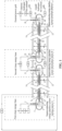
FIG. 1 is a schematic diagram of the overall structure of the disclosure. -
FIG. 2 is a structural cross-section schematic diagram of the liquid hydrogen superconducting pipeline system with the liquid nitrogen cold shields. -
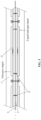
FIG. 3 is a schematic diagram of the multi-layer structure of the liquid hydrogen superconducting pipeline system with the liquid nitrogen cold shields. - The reference numbers in the accompanying drawings include: a first electrical power input rectifying station 1, a first normal temperature cable group 2, a first low
temperature cable group 3, a first adapter 4, a first liquidhydrogen storage container 5, awater electrolysis device 6, a hydrogen liquefaction device 7, a firstsuperconducting cable group 8, a first liquidhydrogen delivery pipeline 9, a first liquid nitrogen evaporationcold shield 10, a first externalcold insulation layer 11, a liquidnitrogen supply pipeline 12, a first liquid nitrogen pressure-reducingvalve 13, anitrogen recovery pipeline 14, anitrogen re-liquefaction device 15, a second liquid nitrogen evaporationcold shield 16, a second liquid nitrogen pressure-reducingvalve 17, a second liquidhydrogen storage container 18, asecond adapter 19, a second lowtemperature cable group 20, a second normaltemperature cable group 21, a second electrical powerinput rectifying station 22, a third normaltemperature cable group 23, a third lowtemperature cable group 24, athird adapter 25, a third liquidhydrogen storage container 26, ahydrogen re-liquefaction device 27, aliquid hydrogen pump 28, a secondsuperconducting cable group 29, a second liquidhydrogen delivery pipeline 30, a third liquid nitrogen pressure-reducingvalve 31, a third liquid nitrogen evaporationcold shield 32, a second external cold insulation layer 33, a fourth liquid nitrogen pressure-reducingvalve 34, a fourth liquid nitrogen evaporationcold shield 35, a fourth liquidhydrogen storage container 36, afourth adapter 37, a fourth lowtemperature cable group 38, a fourth normaltemperature cable group 39, an outputpower inverter station 40, a liquid hydrogen pressurizedloading facility 41, a hydrogen heating andpressuring device 42, a hydrogenpower generation device 43, a cablesupport pulley block 44, an internalheat insulation layer 45. - A direct-current superconducting liquid hydrogen energy pipeline system with liquid nitrogen cold shields includes: a superconducting energy pipeline system starting station A, a superconducting energy pipeline system intermediate station B, a superconducting energy pipeline system terminal station C, a liquid hydrogen superconducting pipeline system with the liquid nitrogen cold shields, a nitrogen re-liquefaction device and other subsystems.
- The superconducting energy pipeline system starting station A may receive electrical power of renewable energy and electrolyze water by using abundant electrical power of renewable energy to produce hydrogen, and liquefy the hydrogen. The superconducting energy pipeline system starting station A may also be connected to the liquid hydrogen superconducting pipeline system with the liquid nitrogen cold shields through liquid hydrogen superconducting pipelines to deliver the electrical power and liquid hydrogen energy.
- The superconducting energy pipeline system intermediate station B may be connected to the liquid hydrogen superconducting pipeline system with the liquid nitrogen cold shields through liquid hydrogen superconducting pipelines to deliver the electrical power and liquid hydrogen energy. The superconducting energy pipeline system intermediate station B may also receive new external electrical power, re-liquefy the evaporated hydrogen, and re-pressurize the unevaporated liquid hydrogen. The superconducting energy pipeline system intermediate station B of the disclosure represents only one functional schematic station, and in actual implementation, the superconducting energy pipeline system intermediate station B is composed of intermediate station B1, intermediate station B2, ..., intermediate station Bn with a same structure as the intermediate station B connected in series in sequence.
- The superconducting energy pipeline system terminal station C may be connected to the liquid hydrogen superconducting pipeline system with the liquid nitrogen cold shields through liquid hydrogen superconducting pipelines to deliver the electrical power and liquid hydrogen energy. The superconducting energy pipeline system terminal station C may also convert the received direct-current into alternating-current, and deliver the electrical power to the external power grid. The superconducting energy pipeline system terminal station C may also pressurize the received liquid hydrogen for sale and utilize the evaporated gaseous hydrogen for power generation or external sales.
- The liquid hydrogen superconducting pipeline with the liquid nitrogen cold shields mainly plays the role of connecting the superconducting energy pipeline system starting station A, the superconducting energy pipeline system intermediate station B and the superconducting energy pipeline system terminal station C. At the same time, the system has separately laid liquid nitrogen pipeline and nitrogen pipeline to provide liquid nitrogen for cold shielding and recover the evaporated nitrogen after cold shielding.
- The liquid hydrogen superconducting pipeline with the liquid nitrogen cold shields includes a liquid hydrogen delivery pipeline, liquid nitrogen cold shields, an external cold insulation layer and a superconducting cable group arranged inside the liquid hydrogen delivery pipeline. The liquid nitrogen cold shields are arranged in segments outside the liquid hydrogen delivery pipeline, and the bottom and top of each of the liquid nitrogen cold shields are respectively connected to a liquid nitrogen delivery pipeline and a low temperature nitrogen recovery pipeline through pipelines.
- The nitrogen re-liquefaction device mainly re-liquefies the evaporated nitrogen after cold shielding into liquid nitrogen and supplements the liquid nitrogen into the liquid nitrogen pipeline. The setting of the nitrogen re-liquefaction device is related to the cold energy consumption of the liquid nitrogen. The nitrogen re-liquefaction device may be set in any area that requires cold energy. The number of the nitrogen re-liquefaction device depends on the evaporation needs of the actual pipeline system.
- Hereinafter, the internal configuration of each subsystem and the connection relationships between subsystems will be described in detail with reference to the accompanying drawings.
- As shown in
FIG. 1 : - 1) the superconducting energy pipeline system starting station A includes: a first electrical power input rectifying station 1, a first normal temperature cable group 2, a first low
temperature cable group 3, a first adapter 4, a first liquidhydrogen storage container 5, awater electrolysis device 6, a hydrogen liquefaction device 7, a firstsuperconducting cable group 8, and a first liquidhydrogen delivery pipeline 9, etc. - The upstream clean energy base is connected to the first electrical power input rectifying station 1 to receive external electrical power, the first electrical power input rectifying station 1 is connected to the first normal temperature cable group 2, the first normal temperature cable group 2 is connected to the first low
temperature cable group 3, the first lowtemperature cable group 3 is connected to the first adapter 4, and the first adapter 4 is connected to the firstsuperconducting cable group 8 to deliver the electrical power to the superconducting energy pipeline system intermediate station B through superconductivity. - The first electrical power input rectifying station 1 delivers abundant electrical power to the
water electrolysis device 6 through cables. The electrical power is used to decompose water into hydrogen and oxygen in thewater electrolysis device 6. The oxygen is sold or discharged externally. The hydrogen is delivered to the hydrogen liquefaction device 7 through pipelines to produce liquid hydrogen. The hydrogen liquefaction device 7 delivers the liquid hydrogen to the first liquidhydrogen storage container 5 through a dedicated pipeline for liquid hydrogen, and the first liquidhydrogen storage container 5 delivers the liquid hydrogen to downstream location through the first liquidhydrogen delivery pipeline 9. - The first electrical power input rectifying station 1 includes the combination of common power equipment such as high-voltage direct-current rectifiers, rectifier transformers, filters, disconnecting switches, chopper switches and chopper resistors, which are mainly configured depending on the requirements of power input or output.
- The first normal temperature cable group 2 refers to power cables used in a direct-current power transmission and distribution system.
- The first low
temperature cable group 3 refers to low temperature resistant cables with insulating materials such as polypropylene laminated paper (PPLP), basalt fiber, or the like as a main insulating layer. - The first liquid
hydrogen storage container 5 may be various types of heat insulation containers. The forms of heat insulation include but are not limited to vacuum powder heat insulation, vacuum-liquid nitrogen-vacuum three-layer heat insulation, vapor-phase self-cold-shielding composite heat insulation, etc. - The
water electrolysis device 6 may be a device such as an alkaline electrolysis cell (ACE), a proton exchange membrane (PEM) electrolysis cell, and a solid oxide electrolysis cell (SOEC), and its supporting facilities. - The first
superconducting cable group 8 is composed of multiple superconducting cables, and a single cable is composed of a cable skeleton, a superconductor, a shielding layer and a protective casing. The core conductive material may be BSCCO tape, YBCO tape, MgB superconducting material, etc. The skeleton material is copper, and the low temperature insulation material is generally PPLP. - 2) The superconducting energy pipeline system intermediate station B includes a second liquid
hydrogen storage container 18, asecond adapter 19, a second lowtemperature cable group 20, a second normaltemperature cable group 21, a second electrical powerinput rectifying station 22, a third normaltemperature cable group 23, a third lowtemperature cable group 24, athird adapter 25, a third liquidhydrogen storage container 26, ahydrogen re-liquefaction device 27, aliquid hydrogen pump 28, a secondsuperconducting cable group 29, and a second liquidhydrogen delivery pipeline 30, etc. - The second liquid
hydrogen storage container 18 is connected to the upstream firstsuperconducting cable group 8 through a superconducting cable, and connected to the upstream first liquidhydrogen delivery pipeline 9 through a pipeline. The firstsuperconducting cable group 8 is connected to thesecond adapter 19, thesecond adapter 19 is connected to the second lowtemperature cable group 20, and the second lowtemperature cable group 20 is ultimately connected to the second normaltemperature cable group 21 to deliver the electrical power to the second electrical powerinput rectifying station 22. The second electrical powerinput rectifying station 22 can not only receive external electrical power, but also deliver the electrical power to the outside. The second electrical powerinput rectifying station 22 is connected to the third normaltemperature cable group 23, the third normaltemperature cable group 23 is connected to the third lowtemperature cable group 24, the third lowtemperature cable group 24 is connected to thethird adapter 25, and thethird adapter 25 is connected to the secondsuperconducting cable group 29 to deliver the electrical power to the superconducting energy pipeline system terminal station C through superconducting cable. The second liquidhydrogen storage container 18 performs gas-liquid separation on the received liquid hydrogen, the vapor-phase from the second liquidhydrogen storage container 18 is delivered through a pipeline to thehydrogen re-liquefaction device 27 for re-liquefaction, and the re-liquefied liquid hydrogen is delivered through a pipeline to the third liquidhydrogen storage container 26. The liquid-phase from the second liquidhydrogen storage container 18 is delivered through a pipeline to theliquid hydrogen pump 28 for pressurization, and the pressurized liquid hydrogen is delivered to the third liquidhydrogen storage container 26 through a pipeline to cooperate with the next round of superconducting delivery. - The
liquid hydrogen pump 28 may be a centrifugal pump, a diaphragm pump, a bellows pump, a piston pump, or the like. - 3) The superconducting energy pipeline system terminal station C includes a second
superconducting cable group 29, a second liquidhydrogen delivery pipeline 30, a fourth liquidhydrogen storage container 36, afourth adapter 37, a fourth lowtemperature cable group 38, a fourth normaltemperature cable group 39, an outputpower inverter station 40, a liquid hydrogen pressurizedloading facility 41, a hydrogen heating and pressuringdevice 42, and a hydrogenpower generation device 43. - The fourth liquid
hydrogen storage container 36 is connected to the upstream secondsuperconducting cable group 29 through a superconducting cable, and connected to the upstream second liquidhydrogen delivery pipeline 30 through a pipeline. The secondsuperconducting cable group 29 is connected to thefourth adapter 37, thefourth adapter 37 is connected to the fourth lowtemperature cable group 38, and the fourth lowtemperature cable group 38 is ultimately connected to the fourth normaltemperature cable group 39 to deliver the electrical power to the outputpower inverter station 40. The outputpower inverter station 40 can not only receive superconducting electrical power and electrical power generated through hydrogen, but also deliver the electrical power to the outside. The received hydrogen is decompressed and separated through the fourth liquidhydrogen storage container 36. Vapor-phase from the fourth liquidhydrogen storage container 36 is delivered to the hydrogen heating and pressuringdevice 42 through a pipeline to increase the temperature to normal temperature and increase the pressure. Hydrogen at normal temperature is delivered to the hydrogenpower generation device 43 through a pipeline to produce electrical power. The electrical power produced in the hydrogenpower generation device 43 is delivered to the outputpower inverter station 40, and then the collected electrical power is delivered to the external power grid. Liquid-phase from the fourth liquidhydrogen storage container 36 is delivered to the liquid hydrogenpressurization loading facility 41 through a pipeline for pressurization, and the pressurized liquid hydrogen is delivered to users of the liquid hydrogen through a liquid hydrogen tanker. - The hydrogen heating and pressuring
device 42 may be a combination of an air-heated aluminum finned re-heater, a hydrogen compressor, and auxiliary equipment. - The hydrogen
power generation device 43 may be various types of fuel cells (such as proton exchange membrane fuel cells, alkaline fuel cells and solid oxide fuel cells, etc.), pure hydrogen/hydrogen-blended gas turbines, pure hydrogen/hydrogen-blended internal combustion engines, etc., the corresponding hydrogen power generation device is selected based on hydrogen transmission scale and local resources. - The liquid hydrogen pressurized
loading facility 41 is composed of a liquid hydrogen pump, a quantitative loading system, a liquid hydrogen loading hose, a weighbridge, an auxiliary production facility, and the like. - 4) The structure of the liquid hydrogen superconducting pipeline with the liquid nitrogen cold shields is shown in
FIG. 2 andFIG. 3 . A firstsuperconducting cable group 8, a cablesupport pulley block 44, a first liquidhydrogen delivery pipeline 9, an internalheat insulation layer 45, a first liquid nitrogenevaporation cold shield 10, a first externalcold insulation layer 11, a liquidnitrogen supply pipeline 12, a first liquid nitrogen pressure-reducingvalve 13, anitrogen recovery pipeline 14, and the like are included. - A cross-sectional schematic diagram of a liquid hydrogen superconducting pipe provided with liquid nitrogen cold shields is shown in
Fig. 2 . A firstsuperconducting cable group 8, a cablesupport pulley block 44, a first liquidhydrogen delivery pipeline 9, an internalheat insulation layer 45, a first liquid nitrogenevaporation cold shield 10, and a first externalcold insulation layer 11, which are arranged coaxially from inside to outside, are included. Moreover, a liquidnitrogen supply pipeline 12, a first liquid nitrogen pressure-reducingvalve 13, anitrogen recovery pipeline 14, and the like, which are constructed collaboratively, are included. - [0043] The first
superconducting cable group 8 is used for superconducting power transmission. The firstsuperconducting cable group 8 is composed of a copper skeleton, a superconducting material, an electrical insulation layer, a protective casing and a cable assembly rack, etc., and is used for power transmission. - [0044] The first layer, i.e., the first liquid
hydrogen delivery pipeline 9, is used for liquid hydrogen transmission, and for cooling the firstsuperconducting cable group 8 at the same time. A cablesupport pulley block 44 is arranged inside the first liquidhydrogen delivery pipeline 9 to support the superconducting cable, to assist in erecting the superconducting cables in the center of the liquid hydrogen pipeline, and to ensure that the superconducting cables are in the most favorable heat dissipation position, thereby avoiding the problem that the irregular laying of the superconducting cable leads to excessive resistance in the liquid hydrogen transmission flow channel. - [0045] The second layer, i.e., the internal
heat insulation layer 45, is used for isolating liquid hydrogen and liquid nitrogen, and may be a high-density heat insulation material or a vacuum heat insulation structure. - [0046] The third layer, i.e., the first liquid nitrogen
evaporation cold shield 10, is mainly used to load liquid nitrogen, provide cold shielding for heat leakage for the liquid hydrogen in the first layer, and reduce the evaporation rate of the liquid hydrogen. - [0047] The fourth layer, i.e., the first external
cold insulation layer 11, is used to isolate the heat exchange between the liquid nitrogen and the external environment, and is generally made of a low-density heat insulation material. The external cold insulation layer also includes conventional attached structures such as a moisture barrier and a protective layer. - [0048] The internal
heat insulation layer 45 may adopt high-vacuum multi-layer winding heat insulation: using materials such as aluminum foil of 0.006 mm as reflective shield, cellophane of 0.1 mm as the spacer, and simultaneously, the interlayer is filled with 5A molecular sieves or activated carbon adsorbents to absorb any leaked hydrogen, in order to maintain the vacuum in the interlayer for a long term. - [0049] The first liquid nitrogen
evaporation cold shield 10 is a cold shield area located outside the liquid hydrogen pipeline for isolating liquid hydrogen. Considering the cold insulation effect, the zero-pressure evaporation cold shield technology can be used to maintain a temperature of 77K to ensure the lowest cold leakage effect of the liquid hydrogen inside. The specific structure of the first liquid nitrogenevaporation cold shield 10 may be a concave jacketed tubing prefabricated in advance, or a cold shield tubing directly welded onto the outside of the liquid hydrogen pipeline. - [0050] The first external
cold insulation layer 11 is a conventional low temperature cold insulation material, and the outer surface of the heat insulation material is in contact with the atmosphere. Common cold insulation methods for liquid nitrogen engineering and LNG engineering pipeline can be used. The heat insulation structure includes materials such as polyurethane, polyisocyanurate, and low-temperature elastomeric insulation, along with details like a moisture barrier and a protective layer. - [0051] 5) The nitrogen re-liquefaction device mainly includes the
nitrogen re-liquefaction device 15. - [0052] The
nitrogen recovery pipeline 14 is connected to thenitrogen re-liquefaction device 15 through a pipeline and thenitrogen re-liquefaction device 15 is connected to the liquidnitrogen supply pipeline 12 through a pipeline. - [0053] The working principle of the disclosure:
- [0054] The core of the disclosure is to separate low temperature nitrogen after endothermic gasification and liquid nitrogen from the superconducting pipeline system as two separate accompanying pipelines. In this way, liquid nitrogen is injected into the main structure in segments for cold shielding, thereby avoiding the problems of inconsistent steel pipe shrinkage rates and design and manufacturing difficulties caused by inconsistent temperatures in the existing technology where the entire liquid hydrogen pipeline and liquid nitrogen pipeline are coaxially laid.
- [0055] Furthermore, in order to improve the cooling effect of superconducting cables in liquid hydrogen, a support pulley block is innovatively used inside the liquid hydrogen pipeline in the disclosure to assist in erecting superconducting cables in the center of the liquid hydrogen pipeline, ensuring that the superconducting cables are in the most favorable heat dissipation position, and at the same time avoiding the problem that the irregular laying of the superconducting cable leads to excessive resistance in the liquid hydrogen transmission flow channel.
- [0056] Furthermore, the specific system settings of the superconducting energy pipeline system starting station A, the superconducting energy pipeline system intermediate station B and the superconducting energy pipeline system terminal station C are provided in the disclosure. By effectively dividing long-distance energy transmission into a multi-segment compositional structure, the implementation difficulty of long-distance hydrogen-power superconducting hybrid energy pipeline is reduced.
Claims (10)
- A direct-current superconducting liquid hydrogen energy pipeline system with liquid nitrogen cold shields, comprising: a superconducting energy pipeline system starting station A, a superconducting energy pipeline system intermediate station B and a superconducting energy pipeline system terminal station C, which are connected in sequence through a liquid hydrogen superconducting pipeline with the liquid nitrogen cold shields; wherein the liquid hydrogen superconducting pipeline with the liquid nitrogen cold shields comprises a liquid hydrogen delivery pipeline, liquid nitrogen cold shields, an external cold insulation layer, and a superconducting cable group arranged inside the liquid hydrogen delivery pipeline; the liquid nitrogen cold shields are arranged in segments outside the liquid hydrogen delivery pipeline, and the bottom and top of each of the liquid nitrogen cold shields are respectively connected to a liquid nitrogen supply pipeline and a nitrogen recovery pipeline through pipelines; and the nitrogen recovery pipeline is connected to a nitrogen re-liquefaction device through a pipeline, and the nitrogen re-liquefaction device is connected to the liquid nitrogen supply pipeline through a pipeline.
- The direct-current superconducting liquid hydrogen energy pipeline system with the liquid nitrogen cold shields of claim 1, wherein the superconducting energy pipeline system starting station A comprises: a first electrical power input rectifying station, a first normal temperature cable group, a first low temperature cable group, a first adapter, a first liquid hydrogen storage container, a water electrolysis device, a hydrogen liquefaction device, a first superconducting cable group and a first liquid hydrogen delivery pipeline; wherein the first electrical power input rectifying station, the first normal temperature cable group, the first low temperature cable group, the first adapter and the first superconducting cable group are connected in sequence; the first electrical power input rectifying station, the water electrolysis device, the hydrogen liquefaction device, the first liquid hydrogen storage container and the first liquid hydrogen delivery pipeline are connected in sequence; and the first low temperature cable group, the first adapter and the first superconducting cable group are arranged in the first liquid hydrogen storage container.
- The direct-current superconducting liquid hydrogen energy pipeline system with the liquid nitrogen cold shields of claim 1, wherein the superconducting energy pipeline system intermediate station B comprises: a second liquid hydrogen storage container, a second adapter, a second low temperature cable group, a second normal temperature cable group, a second electrical power input rectifying station, a third normal temperature cable group, a third low temperature cable group, a third adapter, a third liquid hydrogen storage container, a second superconducting cable group and a second liquid hydrogen delivery pipeline; wherein the second adapter, the second low temperature cable group, the second normal temperature cable group, the second electrical power input rectifying station, the third normal temperature cable group, the third low temperature cable group, the third adapter and the second superconducting cable group are connected in sequence; the second adapter and the second low temperature cable group are arranged in the second liquid hydrogen storage container; and the third low temperature cable group, the third adapter and the second superconducting cable group are arranged in the third liquid hydrogen storage container.
- The direct-current superconducting liquid hydrogen energy pipeline system with the liquid nitrogen cold shields of claim 3, wherein a vapor-phase outlet of the second liquid hydrogen storage container is connected to a hydrogen re-liquefaction device through a pipeline, and the hydrogen re-liquefaction device is connected to the third liquid hydrogen storage container through a pipeline.
- The direct-current superconducting liquid hydrogen energy pipeline system with the liquid nitrogen cold shields of claim 3, wherein a liquid-phase of the second liquid hydrogen storage container is connected to a liquid hydrogen pump through a pipeline, and the liquid hydrogen pump is connected to the third liquid hydrogen storage container through a pipeline.
- The direct-current superconducting liquid hydrogen energy pipeline system with the liquid nitrogen cold shields of claim 1, wherein the superconducting energy pipeline system terminal station C comprises: a second superconducting cable group, a second liquid hydrogen delivery pipeline, a fourth liquid hydrogen storage container, a fourth adapter, a fourth low temperature cable group, a fourth normal temperature cable group, an output power inverter station, a liquid hydrogen pressurized loading facility, a hydrogen heating and pressuring device, and a hydrogen power generation device; wherein the second superconducting cable group, the fourth adapter, the fourth low temperature cable group, the fourth normal temperature cable group and the output power inverter station are connected in sequence; and the second superconducting cable group, the fourth adapter and the fourth low temperature cable group are arranged in the fourth liquid hydrogen storage container.
- The direct-current superconducting liquid hydrogen energy pipeline system with the liquid nitrogen cold shields of claim 6, wherein a vapor-phase of the fourth liquid hydrogen storage container is connected to the hydrogen heating and pressuring device through a pipeline, and the hydrogen heating and pressuring device is connected to the hydrogen power generation device and the output power inverter station in sequence through pipelines.
- The direct-current superconducting liquid hydrogen energy pipeline system with the liquid nitrogen cold shields of claim 6, wherein a liquid-phase of the fourth liquid hydrogen storage container is connected to the liquid hydrogen pressurized loading facility through a pipeline.
- The direct-current superconducting liquid hydrogen energy pipeline system with the liquid nitrogen cold shields of claim 1, wherein a triangular support pulley block is arranged inside the liquid hydrogen delivery pipeline, superconducting cables are installed on the support pulley block, and an internal heat insulation layer is arranged between the liquid hydrogen delivery pipeline and the liquid nitrogen cold shield.
- The direct-current superconducting liquid hydrogen energy pipeline system with the liquid nitrogen cold shields of claim 1, wherein the superconducting energy pipeline system intermediate station B is composed of intermediate stations B1, B2, ..., Bn with a same structure connected in series in sequence.
Applications Claiming Priority (2)
| Application Number | Priority Date | Filing Date | Title |
|---|---|---|---|
| CN202210944639.XA CN115307062A (en) | 2022-08-08 | 2022-08-08 | Direct-current superconducting liquid hydrogen energy pipeline system with liquid nitrogen cold screen |
| PCT/CN2023/105912 WO2024032286A1 (en) | 2022-08-08 | 2023-07-05 | Direct-current superconducting liquid hydrogen energy pipeline system with liquid nitrogen cold shields |
Publications (2)
| Publication Number | Publication Date |
|---|---|
| EP4524458A1 true EP4524458A1 (en) | 2025-03-19 |
| EP4524458A4 EP4524458A4 (en) | 2025-09-03 |
Family
ID=83861051
Family Applications (1)
| Application Number | Title | Priority Date | Filing Date |
|---|---|---|---|
| EP23851511.8A Pending EP4524458A4 (en) | 2022-08-08 | 2023-07-05 | DC superconducting liquid hydrogen energy piping system with liquid nitrogen cold shields |
Country Status (4)
| Country | Link |
|---|---|
| US (1) | US20250166870A1 (en) |
| EP (1) | EP4524458A4 (en) |
| CN (1) | CN115307062A (en) |
| WO (1) | WO2024032286A1 (en) |
Families Citing this family (4)
| Publication number | Priority date | Publication date | Assignee | Title |
|---|---|---|---|---|
| CN115307062A (en) * | 2022-08-08 | 2022-11-08 | 成都精智艺科技有限责任公司 | Direct-current superconducting liquid hydrogen energy pipeline system with liquid nitrogen cold screen |
| CN116260187A (en) * | 2023-03-20 | 2023-06-13 | 西安交通大学 | An Offshore Wind Power and Hydrogen Power Combined Transmission System Based on Superconducting Technology |
| CN115978444B (en) * | 2023-03-21 | 2023-05-23 | 北京中科富海低温科技有限公司 | Low-temperature transmission system |
| CN117856147B (en) * | 2023-12-05 | 2024-09-13 | 国电银河海兴新能源有限公司 | Cable joint heat abstractor |
Family Cites Families (13)
| Publication number | Priority date | Publication date | Assignee | Title |
|---|---|---|---|---|
| JPS6419618A (en) * | 1987-07-15 | 1989-01-23 | Hitachi Ltd | Superconductive bus-bar |
| RU2056689C1 (en) * | 1994-12-13 | 1996-03-20 | Поправкин Николай Алексеевич | Plant for keeping gas-filled cables under gage pressure |
| JP4609121B2 (en) * | 2004-07-29 | 2011-01-12 | 住友電気工業株式会社 | Superconducting cable line |
| JP2006180588A (en) * | 2004-12-21 | 2006-07-06 | Sumitomo Electric Ind Ltd | Power extraction structure for superconducting equipment |
| US8280467B2 (en) * | 2008-10-03 | 2012-10-02 | American Superconductor Corporation | Electricity transmission cooling system |
| JP2013140764A (en) * | 2011-12-06 | 2013-07-18 | Sumitomo Electric Ind Ltd | Superconducting cable, superconducting cable line, method for laying superconducting cable, and method for operating superconducting cable line |
| CN105162158B (en) * | 2015-09-29 | 2018-01-02 | 四川师范大学 | A kind of liquid hydrogen liquid oxygen liquefied nitrogen, superconducting direct current cables compound energy Transmission system |
| CN209340880U (en) * | 2019-01-02 | 2019-09-03 | 西南石油大学 | A superconducting energy pipeline system based on LNG pre-cooling transmission |
| CN110853829A (en) * | 2019-11-15 | 2020-02-28 | 深圳市开迩文科技有限公司 | Superconducting material constant temperature system |
| CN113074281A (en) * | 2020-11-17 | 2021-07-06 | 杨润童 | Liquefied gas energy storage and transportation pipeline and superconducting transmission line system and method |
| CN113922371B (en) * | 2021-10-13 | 2023-05-26 | 中国石油工程建设有限公司 | Super-long-distance hydrogen-electricity hybrid conveying integrated system based on superconducting technology |
| CN217784864U (en) * | 2022-08-08 | 2022-11-11 | 成都精智艺科技有限责任公司 | Direct-current superconducting liquid hydrogen energy pipeline system with liquid nitrogen cold shield |
| CN115307062A (en) * | 2022-08-08 | 2022-11-08 | 成都精智艺科技有限责任公司 | Direct-current superconducting liquid hydrogen energy pipeline system with liquid nitrogen cold screen |
-
2022
- 2022-08-08 CN CN202210944639.XA patent/CN115307062A/en active Pending
-
2023
- 2023-07-05 WO PCT/CN2023/105912 patent/WO2024032286A1/en not_active Ceased
- 2023-07-05 US US18/835,710 patent/US20250166870A1/en active Pending
- 2023-07-05 EP EP23851511.8A patent/EP4524458A4/en active Pending
Also Published As
| Publication number | Publication date |
|---|---|
| WO2024032286A1 (en) | 2024-02-15 |
| CN115307062A (en) | 2022-11-08 |
| EP4524458A4 (en) | 2025-09-03 |
| US20250166870A1 (en) | 2025-05-22 |
Similar Documents
| Publication | Publication Date | Title |
|---|---|---|
| WO2024032286A1 (en) | Direct-current superconducting liquid hydrogen energy pipeline system with liquid nitrogen cold shields | |
| CN114498756B (en) | A composite superconducting microgrid system for mitigating power fluctuations in offshore wind power. | |
| CN113922371B (en) | Super-long-distance hydrogen-electricity hybrid conveying integrated system based on superconducting technology | |
| CN109854825B (en) | Liquid hydrogen-liquefied natural gas-high temperature superconducting hybrid energy transmission pipeline | |
| CN112448413B (en) | A near-zero carbon emission distributed energy supply system and method | |
| CN109140064B (en) | Superconducting energy pipeline for low-temperature fuel conduction cooling | |
| US12184076B2 (en) | Green energy transportation system and energy transportation method | |
| CN102679152B (en) | United long-range transmission system for liquefied natural gas and high-temperature superconducting electric energy | |
| CN110021460B (en) | A shock-resistant and ablation-resistant superconducting energy pipeline | |
| AU2004285058A1 (en) | Conduit component for a power supply network, use thereof, method for transporting cryogenic energy carriers in conduits and devices suitable therefor | |
| Xiao et al. | Development of a 10 kA HTS DC power cable | |
| CN217784864U (en) | Direct-current superconducting liquid hydrogen energy pipeline system with liquid nitrogen cold shield | |
| WO2011149562A2 (en) | Superconducting electricity transmission system | |
| CN113074281A (en) | Liquefied gas energy storage and transportation pipeline and superconducting transmission line system and method | |
| Hassenzahl et al. | A high-power superconducting DC cable | |
| WO2025097541A1 (en) | Offshore wind power energy storage vessel and offshore wind power transmission method | |
| Yamada et al. | Study on 1 GW class hybrid energy transfer line of hydrogen and electricity | |
| Wang et al. | Low-carbon hydrogen-electricity energy supply networks for China-Thailand international high-speed railway | |
| CN114458959A (en) | Hydrogen use efficiency improving process for hydrogenation station | |
| Yu et al. | Feasibility and economical analysis of the superconducting cable and hydrogen hybrid transmission gallery | |
| CN116260187A (en) | An Offshore Wind Power and Hydrogen Power Combined Transmission System Based on Superconducting Technology | |
| CN118640636A (en) | Composite cryogenic refrigeration system coupling hydrogen liquefaction and superconducting motor liquid hydrogen cooling | |
| Ivanov et al. | A proposal of the hybrid energy transfer pipe | |
| CN109132251B (en) | Offshore renewable energy transport system and method based on liquid gas energy storage | |
| CN222632198U (en) | Light offshore booster station and offshore hydrogen production and hydrogenation fusion platform |
Legal Events
| Date | Code | Title | Description |
|---|---|---|---|
| STAA | Information on the status of an ep patent application or granted ep patent |
Free format text: STATUS: THE INTERNATIONAL PUBLICATION HAS BEEN MADE |
|
| PUAI | Public reference made under article 153(3) epc to a published international application that has entered the european phase |
Free format text: ORIGINAL CODE: 0009012 |
|
| STAA | Information on the status of an ep patent application or granted ep patent |
Free format text: STATUS: REQUEST FOR EXAMINATION WAS MADE |
|
| 17P | Request for examination filed |
Effective date: 20241210 |
|
| AK | Designated contracting states |
Kind code of ref document: A1 Designated state(s): AL AT BE BG CH CY CZ DE DK EE ES FI FR GB GR HR HU IE IS IT LI LT LU LV MC ME MK MT NL NO PL PT RO RS SE SI SK SM TR |
|
| RAP1 | Party data changed (applicant data changed or rights of an application transferred) |
Owner name: XI'AN JIAOTONG UNIVERSITY Owner name: STATE GRID ECONOMIC AND TECHNOLOGICAL RESEARCHINSTITUTE CO., LTD Owner name: CHENGDU JINGZHIYI TECHNOLOGY CO., LTD. |
|
| RAP3 | Party data changed (applicant data changed or rights of an application transferred) |
Owner name: XI'AN JIAOTONG UNIVERSITY Owner name: CHENGDU JINGZHIYI TECHNOLOGY CO., LTD. Owner name: STATE GRID ECONOMIC AND TECHNOLOGICAL RESEARCHINSTITUTE CO., LTD |
|
| A4 | Supplementary search report drawn up and despatched |
Effective date: 20250806 |
|
| RIC1 | Information provided on ipc code assigned before grant |
Ipc: F17D 1/08 20060101AFI20250731BHEP Ipc: H02G 15/34 20060101ALI20250731BHEP Ipc: H01B 12/00 20060101ALI20250731BHEP |
|
| DAV | Request for validation of the european patent (deleted) | ||
| DAX | Request for extension of the european patent (deleted) |