EP4524444A1 - Ring body, pipe joint, and method for joining pipes using said ring body - Google Patents
Ring body, pipe joint, and method for joining pipes using said ring body Download PDFInfo
- Publication number
- EP4524444A1 EP4524444A1 EP23831293.8A EP23831293A EP4524444A1 EP 4524444 A1 EP4524444 A1 EP 4524444A1 EP 23831293 A EP23831293 A EP 23831293A EP 4524444 A1 EP4524444 A1 EP 4524444A1
- Authority
- EP
- European Patent Office
- Prior art keywords
- socket
- spigot
- ring
- pipe
- circumferential surface
- Prior art date
- Legal status (The legal status is an assumption and is not a legal conclusion. Google has not performed a legal analysis and makes no representation as to the accuracy of the status listed.)
- Pending
Links
Images










Classifications
-
- F—MECHANICAL ENGINEERING; LIGHTING; HEATING; WEAPONS; BLASTING
- F16—ENGINEERING ELEMENTS AND UNITS; GENERAL MEASURES FOR PRODUCING AND MAINTAINING EFFECTIVE FUNCTIONING OF MACHINES OR INSTALLATIONS; THERMAL INSULATION IN GENERAL
- F16L—PIPES; JOINTS OR FITTINGS FOR PIPES; SUPPORTS FOR PIPES, CABLES OR PROTECTIVE TUBING; MEANS FOR THERMAL INSULATION IN GENERAL
- F16L21/00—Joints with sleeve or socket
- F16L21/08—Joints with sleeve or socket with additional locking means
-
- F—MECHANICAL ENGINEERING; LIGHTING; HEATING; WEAPONS; BLASTING
- F16—ENGINEERING ELEMENTS AND UNITS; GENERAL MEASURES FOR PRODUCING AND MAINTAINING EFFECTIVE FUNCTIONING OF MACHINES OR INSTALLATIONS; THERMAL INSULATION IN GENERAL
- F16L—PIPES; JOINTS OR FITTINGS FOR PIPES; SUPPORTS FOR PIPES, CABLES OR PROTECTIVE TUBING; MEANS FOR THERMAL INSULATION IN GENERAL
- F16L21/00—Joints with sleeve or socket
- F16L21/02—Joints with sleeve or socket with elastic sealing rings between pipe and sleeve or between pipe and socket, e.g. with rolling or other prefabricated profiled rings
-
- F—MECHANICAL ENGINEERING; LIGHTING; HEATING; WEAPONS; BLASTING
- F16—ENGINEERING ELEMENTS AND UNITS; GENERAL MEASURES FOR PRODUCING AND MAINTAINING EFFECTIVE FUNCTIONING OF MACHINES OR INSTALLATIONS; THERMAL INSULATION IN GENERAL
- F16L—PIPES; JOINTS OR FITTINGS FOR PIPES; SUPPORTS FOR PIPES, CABLES OR PROTECTIVE TUBING; MEANS FOR THERMAL INSULATION IN GENERAL
- F16L21/00—Joints with sleeve or socket
- F16L21/02—Joints with sleeve or socket with elastic sealing rings between pipe and sleeve or between pipe and socket, e.g. with rolling or other prefabricated profiled rings
- F16L21/04—Joints with sleeve or socket with elastic sealing rings between pipe and sleeve or between pipe and socket, e.g. with rolling or other prefabricated profiled rings in which sealing rings are compressed by axially-movable members
Definitions
- the present invention relates to a ring body provided in a pipe joint having a lock ring and a seal ring, a pipe joint equipped with the ring body, and a method for joining pipes using the ring body.
- a ring body 204 that is provided in a pipe joint 201 is known, as illustrated in Fig. 21 and Fig. 22 .
- a spigot 207 of a first pipe 206 is inserted into a socket 209 of a second pipe 208.
- a lock ring 202 is accommodated in a lock ring accommodation groove 210 formed in the inner circumference of the socket 209.
- a seal ring 203 is compressed in a pipe radial direction 211 to seal a space between the outer circumferential surface of the spigot 207 and the inner circumferential surface of the socket 209.
- the socket 209 has, at the inner circumference thereof, a socket sealing surface 212 with which the outer circumferential surface of the seal ring 203 contacts with pressure over the entire circumference, and a socket protrusion 213 which protrudes inward in the pipe radial direction from the interior part of the socket sealing surface 212.
- the ring body 204 has an annular ring main body portion 214 that can be inserted between the inner circumferential surface of the socket protrusion 213 and the outer circumferential surface of the spigot 207, and a deviation prevention member 215 that prevents the ring main body portion 214 from deviating toward a position closer to the opening end of the socket 209.
- the lock ring 202 is accommodated in the lock ring accommodation groove 210.
- the spigot 207 is inserted into the socket 209.
- the ring body 204 is inserted between the socket sealing surface 212 and the outer circumferential surface of the spigot 207 from the opening end of the socket 209, and the ring main body portion 214 of the ring body 204 is pushed in between the inner circumferential surface of the socket protrusion 213 and the outer circumferential surface of the spigot 207.
- the seal ring 203 is pushed in between the socket sealing surface 212 and the outer circumferential surface of the spigot 207 from the opening end of the socket 209.
- the ring main body portion 214 of the ring body 204 is inserted between the inner circumferential surface of the socket protrusion 213 and the outer circumferential surface of the spigot 207, a gap 216 between the socket sealing surface 212 and the outer circumferential surface of the spigot 207 in the pipe radial direction 211 is maintained at a predetermined size that allows the seal ring 203 to be pushed in.
- Japanese Patent Laid-Open No. 2021-67282 can be referred to for a description regarding the ring body 204 described above.
- An object of the present invention is to provide a ring body which, when the ring body is being inserted between a socket sealing surface and the outer circumferential surface of a spigot, even if an insertion amount of the ring body is insufficient, can prevent a seal ring from being excessively compressed in the pipe radial direction by maintaining an interval between the socket sealing surface and the outer circumferential surface of the spigot in the pipe radial direction at an appropriate size that allows the seal ring to be pushed in, and a method for joining pipes using the ring body.
- a ring body of the present invention is a ring body to be provided in a pipe joint, the pipe joint comprising:
- the spigot when joining the first pipe and the second pipe, the spigot is inserted into the socket, the ring body is inserted between the socket sealing surface and the outer circumferential surface of the spigot from the opening end of the socket, and the ring main body portion of the ring body is pushed in between the inner circumferential surface of the socket protrusion and the outer circumferential surface of the spigot.
- the ring body is mounted at the proper position, the interval maintaining parts of the ring body are arranged between the socket sealing surface and the outer circumferential surface of the spigot, and an interval between the socket sealing surface and the outer circumferential surface of the spigot in the pipe radial direction is maintained at a predetermined size that allows the seal ring to be pushed in.
- the seal ring when the seal ring is pushed in between the socket sealing surface and the outer circumferential surface of the spigot from the opening end of the socket, the seal ring can be easily pushed in between the socket sealing surface and the outer circumferential surface of the spigot from the opening end of the socket without the seal ring being excessively compressed in the pipe radial direction.
- the interval maintaining parts are arranged between the socket sealing surface and the outer circumferential surface of the spigot. Therefore, the interval between the socket sealing surface and the outer circumferential surface of the spigot in the pipe radial direction is maintained at a predetermined size that allows the seal ring to be pushed in.
- the seal ring can be easily pushed in between the socket sealing surface and the outer circumferential surface of the spigot from the opening end of the socket without the seal ring being excessively compressed in the pipe radial direction.
- the ring body when joining the first pipe and the second pipe, the ring body is inserted between the socket sealing surface and the outer circumferential surface of the spigot from the opening end of the socket, and the ring main body is pushed in between the inner circumferential surface of the socket protrusion and the outer circumferential surface of the spigot.
- the engagement surface of the ring body is caught on the socket protrusion in the insertion direction of the spigot so that the ring body is thus arranged at the proper position, and the position of the ring body does not deviate further into a deeper portion of the socket relative to the proper position thereof.
- a deeper end of the ring main body portion in a pipe axis direction is positioned closer to the socket opening end than a deeper end of the socket protrusion.
- the engagement surface of the interval maintaining part is caught on the socket protrusion, and the deeper end of the ring main body portion is positioned closer to the socket opening end than the deeper end of the socket protrusion. Therefore, contact between the ring main body portion and the lock ring is prevented, and the occurrence of damage to the ring main body portion can be prevented.
- a pipe joint that includes the ring body of the present invention has:
- the first pipe is joined in a straight condition to the second pipe.
- the first pipe is bent and joined to the second pipe.
- a clearance is formed between the ring body and the seal ring.
- the seal ring contacts the ring body.
- a method for joining pipes using the ring body of the present invention comprises:
- the interval maintaining parts of the ring body are sandwiched between the socket sealing surface and the outer circumferential surface of the spigot, and the interval between the socket sealing surface and the outer circumferential surface of the spigot in the pipe radial direction is maintained at a predetermined size that allows the seal ring to be pushed in.
- the interval maintaining parts are sandwiched between the socket sealing surface and the outer circumferential surface of the spigot, the interval between the socket sealing surface and the outer circumferential surface of the spigot in the pipe radial direction is maintained at a predetermined size that allows the seal ring to be pushed in.
- the seal ring can be easily pushed in between the socket sealing surface and the outer circumferential surface of the spigot from the opening end of the socket.
- the interval maintaining parts are sandwiched between the socket sealing surface and the outer circumferential surface of the spigot. Therefore, the interval between the socket sealing surface and the outer circumferential surface of the spigot in the pipe radial direction is maintained at a predetermined size that allows the seal ring to be pushed in. Thus, the seal ring can be easily pushed in between the socket sealing surface and the outer circumferential surface of the spigot.
- a pipe joint 1 has a spigot 3 formed in a first pipe 2, and a socket 5 formed in a second pipe 4, with the spigot 3 being inserted into the socket 5.
- ductile iron pipes are used for these pipes 2 and 4.
- a lock ring accommodation groove 7 is formed over the entire circumference in the inner circumferential surface of the socket 5.
- a lock ring 8 is accommodated in the lock ring accommodation groove 7.
- the lock ring 8 is a ring having a split structure in which one portion has been cut at a location along the circumferential direction.
- the diameter of the lock ring 8 is expanded by expanding a gap 12 between the cut ends at a cut portion 11 using an expander 13, and the lock ring 8 has elasticity such that its diameter is reduced to return to the original diameter by removing the expander 13 from the cut portion 11.
- a spigot protrusion 15 is formed over the entire circumference at the outer circumference of the spigot 3.
- the spigot protrusion 15 can prevent the spigot 3 from separating from the socket 5 by the spigot protrusion 15 being caught on the lock ring 8 from the socket inner side in a separation direction 6 of the spigot 3.
- a seal ring 19 is provided that is compressed in a pipe radial direction 17 to seal a space between an outer circumferential surface 3a of the spigot 3 and the inner circumferential surface of the socket 5.
- the seal ring 19 is a ring made of rubber.
- the socket 5 has, at the inner circumference thereof, a socket sealing surface 21 with which the outer circumferential surface of the seal ring 19 contacts with pressure over the entire circumference, and a socket protrusion 22 that protrudes inward in the pipe radial direction from a deeper portion of the socket sealing surface 21.
- the socket sealing surface 21 has a tapered surface 25 that decreases in diameter gradually from an opening end face 24 of the socket 5 to the inner side, and an inner circumferential surface 26 that extends to the inner side from the deeper end of the tapered surface 25.
- the inner circumferential surface 26 is formed with a uniform inner diameter in a pipe axis direction 27 and is parallel to the outer circumferential surface 3a of the spigot 3.
- the socket protrusion 22 is formed in a circular shape over the entire circumference between the inner circumferential surface 26 of the socket sealing surface 21 and the lock ring accommodation groove 7.
- the socket protrusion 22 has a first end face 22b that extends from the deeper end of the inner circumferential surface 26 of the socket sealing surface 21 to an inner circumferential surface 22a of the socket protrusion 22, and a second end face 22c that extends from the inner circumferential surface 22a to the lock ring accommodation groove 7.
- the first end face 22b of the socket protrusion 22 is a tapered face whose diameter decreases as it approaches the inner circumferential surface 22a of the socket protrusion 22 from the deeper end of the inner circumferential surface 26 of the socket sealing surface 21.
- the second end face 22c of the socket protrusion 22 is a face which faces toward a deeper portion of the socket 5, and is located at the deeper end of the socket protrusion 22 in the pipe axis direction 27.
- the inner diameter of the inner circumferential surface 26 of the socket sealing surface 21 is set to a larger diameter than the inner diameter of the socket protrusion 22.
- a gland 30 that pushes the seal ring 19 into a deeper portion of the socket 5 is provided at the opening end part of the socket 5.
- the gland 30 has a contact portion 32 that contacts the opening end face 24 of the socket 5 in an insertion direction 31 of the seal ring 19.
- the gland 30 is connected to the opening end part of the socket 5 by a plurality of bolts 33 and nuts 34.
- a ring body 40 is provided between the lock ring 8 and the seal ring 19 in the pipe axis direction 27. As illustrated in Fig. 4 to Fig. 6 , the ring body 40 is made of a material that has elasticity, such as resin.
- the ring body 40 has an annular ring main body portion 41 that can be inserted between the inner circumferential surface 22a of the socket protrusion 22 and the outer circumferential surface 3a of the spigot 3, and a plurality of interval maintaining parts 42 that can be inserted between the inner circumferential surface 26 of the socket sealing surface 21 and the outer circumferential surface 3a of the spigot 3.
- the ring body 40 is a ring having a structure that is split at one location in the circumferential direction, in which any one of the interval maintaining parts 42 is cut at the center.
- the ring main body portion 41 has a quadrilateral cross section.
- the plurality of interval maintaining parts 42 are integrally provided on the ring main body portion 41 at predetermined intervals from each other in a pipe circumference direction 44.
- the interval maintaining part 42 is a protrusion that protrudes from the ring main body portion 41 at a position toward the socket opening end, and protrudes further outward in the pipe radial direction than the ring main body portion 41.
- the interval maintaining part 42 has an engagement surface 45 that is caught on the first end face 22b of the socket protrusion 22 in the insertion direction 31 of the spigot 3.
- the engagement surface 45 is a tapered surface that projects outward in the pipe radial direction 17 from the outer circumferential surface of the ring main body portion 41, and whose diameter increases as it approaches the outer circumferential surface of the interval maintaining part 42 from the outer circumferential surface of the ring main body portion 41.
- An inner diameter d1 of the interval maintaining part 42 is the same as an inner diameter d2 of the ring main body portion 41.
- An outer diameter D1 of the interval maintaining part 42 is larger than an outer diameter D2 of the ring main body portion 41.
- An escape space 46 into which a distal end portion of the seal ring 19 that is compressed can enter is formed at a location which is between one interval maintaining part 42 and another interval maintaining part 42 that are adjacent in the pipe circumference direction 44 and which is closer to the socket opening end than the ring main body portion 41.
- the ring body 40, the seal ring 19, and the gland 30 are externally fitted to the first pipe 2 in advance. Further, the lock ring 8 is accommodated in the lock ring accommodation groove 7 of the second pipe 4. Then, as illustrated in Fig. 3 , the gap 12 of the cut portion 11 of the lock ring 8 is expanded using an expander 13 to thereby expand the diameter of the lock ring 8. Next, as illustrated in Fig. 12 , an L-shaped diameter expansion holder 50 is inserted into the cut portion 11 of the lock ring 8 and the expander 13 is removed, to thereby maintain the lock ring 8 in the state in which its diameter is expanded.
- the spigot 3 is inserted into the socket 5, and the spigot protrusion 15 is passed through from a position close to the socket opening end of the lock ring 8 to a deeper portion of the socket 52.
- the lock ring 8 is maintained in the state in which its diameter is expanded by the diameter expansion holder 50, the spigot protrusion 15 easily passes through the inner circumference of the lock ring 8.
- the diameter expansion holder 50 is removed from the cut portion 11 of the lock ring 8 to thereby cause the gap 12 at the cut portion 11 to be returned to its original size by the elasticity of the lock ring 8, and the lock ring 8 decreases in diameter and clings to the outer circumference of the spigot 3.
- Fig. 13 illustrates a state in which a narrow place has arisen at an upper part of the horizontal pipes 2 and 4.
- the interval 52 at a lower part of the pipes 2 and 4 is enlarged to a larger size than the predetermined size.
- the ring body 40 is moved in the pipe axis direction 27 and inserted between the socket sealing surface 21 and the outer circumferential surface 3a of the spigot 3 from the opening end of the socket 5, and mounted at the proper position.
- the ring main body portion 41 of the ring body 40 is inserted between the inner circumferential surface 22a of the socket protrusion 22 and the outer circumferential surface 3a of the spigot 3.
- the engagement surface 45 of the ring body 40 is caught on the first end face 22b of the socket protrusion 22.
- the interval maintaining parts 42 of the ring body 40 are inserted between the inner circumferential surface 26 of the socket sealing surface 21 and the outer circumferential surface 3a of the spigot 3, and thus the interval 52 between the inner circumferential surface 26 of the socket sealing surface 21 and the outer circumferential surface 3a of the spigot 3 in the pipe radial direction 17 is maintained at a predetermined size required in order to push in the seal ring 19.
- the ring body 40 Because the engagement surface 45 of the ring body 40 is caught on the first end face 22b of the socket protrusion 22, the ring body 40 is mounted at the proper position, and the position of the ring body 40 does not deviate further into a deeper portion of the socket 5 than the proper position.
- the seal ring 19 is inserted between the socket sealing surface 21 and the outer circumferential surface 3a of the spigot 3 from the opening end part of the socket 5, the gland 30 is connected to the opening end part of the socket 5 using the bolts 33 and the nuts 34, and the bolts 33 and the nuts 34 are tightened until the contact portion 32 of the gland 30 comes into contact with the opening end face 24 of the socket 5.
- the insertion amount of the ring body 40 may be insufficient and consequently the ring main body portion 41 does not reach the space between the inner circumferential surface 22a of the socket protrusion 22 and the outer circumferential surface 3a of the spigot 3, and is instead arranged between the inner circumferential surface 26 of the socket sealing surface 21 and the outer circumferential surface 3a of the spigot 3 at a location further toward the opening end than the socket protrusion 22.
- the seal ring 19 is not excessively compressed in the pipe radial direction 17 and the seal ring 19 can be easily pushed in between the socket sealing surface 21 and the outer circumferential surface 3a of the spigot 3 from the opening end part of the socket 5.
- the spigot 3 is inserted into the socket 5, and thereafter the ring body 40 is moved in the pipe axis direction 27 and inserted between the socket sealing surface 21 and the outer circumferential surface 3a of the spigot 3 from the opening end of the socket 5 and mounted at the proper position.
- the ring main body portion 41 of the ring body 40 is inserted between the inner circumferential surface 22a of the socket protrusion 22 and the outer circumferential surface 3a of the spigot 3, and the engagement surface 45 of the ring body 40 is caught on the first end face 22b of the socket protrusion 22.
- the first pipe 2 is bent upward with respect to the horizontal second pipe 4.
- the interval 52 between the inner circumferential surface 26 of the socket sealing surface 21 and the outer circumferential surface 3a of the spigot 3 becomes narrower than the predetermined size at the upper part of the pipes 2 and 4 and becomes wider than the predetermined size at the lower part of the pipes 2 and 4.
- the seal ring 19 is pushed in between the socket sealing surface 21 and the outer circumferential surface 3a of the spigot 3 from the opening end part of the socket 5.
- the excessively compressed portion of the seal ring 19 enters the escape space 46 of the ring body 40 so that a situation in which the seal ring 19 is pushed in insufficiently can be prevented.
- a configuration is adopted so that when the ring body 40 is inserted as far as the proper position, a clearance is formed between the ring body 40 and the seal ring 19.
- a configuration is adopted in which a distance C from the opening end face 24 of the socket 5 to the socket protrusion 22 is shortened compared to the first embodiment, so that the seal ring 19 comes in contact with the ring body 40 when the ring body 40 is inserted as far as the proper position.
- the seal ring 19 is compressed in the pipe radial direction 17, and is also sandwiched between the interval maintaining parts 42 of the ring body 40 and the gland 30 and thereby compressed in the pipe axis direction 27.
- the escape space 46 is formed in the ring body 40, a sufficiently wide space necessary to prevent excessive compression of the seal ring 19 is secured between the socket sealing surface 21 and the outer circumferential surface 3a of the spigot 3. Accordingly, by the distal end portion of the seal ring 19 entering into the escape space 46 of the ring body 40, it is possible to prevent the seal ring 19 from being excessively compressed between the socket sealing surface 21 and the outer circumferential surface 3a of the spigot 3.
- the distance C from the opening end face 24 of the socket 5 to the socket protrusion 22 can be shortened, and the length of the socket 5 in the pipe axis direction 27 can be shortened.
- a configuration is adopted in which the ring body 40 is split at one place, a configuration may also be adopted in which the ring body 40 is divided into a plurality of arc-shaped ring pieces, and adjacent ring pieces are connected together with a connecting member to form the annular ring body 40.
Landscapes
- Engineering & Computer Science (AREA)
- General Engineering & Computer Science (AREA)
- Mechanical Engineering (AREA)
- Joints With Sleeves (AREA)
Abstract
Description
- The present invention relates to a ring body provided in a pipe joint having a lock ring and a seal ring, a pipe joint equipped with the ring body, and a method for joining pipes using the ring body.
- Conventionally, as this type of ring body, a
ring body 204 that is provided in apipe joint 201 is known, as illustrated inFig. 21 andFig. 22 . In thepipe joint 201, aspigot 207 of afirst pipe 206 is inserted into asocket 209 of asecond pipe 208. Alock ring 202 is accommodated in a lockring accommodation groove 210 formed in the inner circumference of thesocket 209. - At a location that is closer to an opening end of the
socket 209 than thelock ring 202, aseal ring 203 is compressed in a piperadial direction 211 to seal a space between the outer circumferential surface of thespigot 207 and the inner circumferential surface of thesocket 209. - The
socket 209 has, at the inner circumference thereof, asocket sealing surface 212 with which the outer circumferential surface of theseal ring 203 contacts with pressure over the entire circumference, and asocket protrusion 213 which protrudes inward in the pipe radial direction from the interior part of thesocket sealing surface 212. - The
ring body 204 has an annular ringmain body portion 214 that can be inserted between the inner circumferential surface of thesocket protrusion 213 and the outer circumferential surface of thespigot 207, and adeviation prevention member 215 that prevents the ringmain body portion 214 from deviating toward a position closer to the opening end of thesocket 209. - When joining the
first pipe 206 and thesecond pipe 208, first, thelock ring 202 is accommodated in the lockring accommodation groove 210. Next, thespigot 207 is inserted into thesocket 209. Thereafter, thering body 204 is inserted between thesocket sealing surface 212 and the outer circumferential surface of thespigot 207 from the opening end of thesocket 209, and the ringmain body portion 214 of thering body 204 is pushed in between the inner circumferential surface of thesocket protrusion 213 and the outer circumferential surface of thespigot 207. - Thereafter, the
seal ring 203 is pushed in between thesocket sealing surface 212 and the outer circumferential surface of thespigot 207 from the opening end of thesocket 209. At such time, as illustrated inFig. 22 , because the ringmain body portion 214 of thering body 204 is inserted between the inner circumferential surface of thesocket protrusion 213 and the outer circumferential surface of thespigot 207, agap 216 between thesocket sealing surface 212 and the outer circumferential surface of thespigot 207 in the piperadial direction 211 is maintained at a predetermined size that allows theseal ring 203 to be pushed in. -
Japanese Patent Laid-Open No. 2021-67282 ring body 204 described above. - In the conventional form described above, when joining the
first pipe 206 and thesecond pipe 208, there is a risk that, as illustrated inFig. 23 , the insertion amount of thering body 204 will be insufficient and consequently the ringmain body portion 214 will not reach the space between the inner circumferential surface of thesocket protrusion 213 and the outer circumferential surface of thespigot 207 and will instead be set between thesocket sealing surface 212 and the outer circumferential surface of thespigot 207 at a location further toward the opening end than thesocket protrusion 213. In such case, there will be a place where thegap 216 between thesocket sealing surface 212 and the outer circumferential surface of thespigot 207 in the piperadial direction 211 is narrower than the predetermined size that allows theseal ring 203 to be pushed in. Therefore, there will be a problem that, when pushing theseal ring 203 in between thesocket sealing surface 212 and the outer circumferential surface of thespigot 207, theseal ring 203 will be excessively compressed in the piperadial direction 211, and the operation to push theseal ring 203 in between thesocket sealing surface 212 and the outer circumferential surface of thespigot 207 will be difficult. - An object of the present invention is to provide a ring body which, when the ring body is being inserted between a socket sealing surface and the outer circumferential surface of a spigot, even if an insertion amount of the ring body is insufficient, can prevent a seal ring from being excessively compressed in the pipe radial direction by maintaining an interval between the socket sealing surface and the outer circumferential surface of the spigot in the pipe radial direction at an appropriate size that allows the seal ring to be pushed in, and a method for joining pipes using the ring body.
- A ring body of the present invention is a ring body to be provided in a pipe joint,
the pipe joint comprising: - a spigot formed in a first pipe;
- a socket formed in a second pipe;
- a lock ring accommodation groove formed in an inner circumference of the socket;
- a lock ring accommodated in the lock ring accommodation groove; and
- a seal ring which, at a location that is closer to an opening end of the socket than the lock ring, is compressed in a pipe radial direction to seal a space between an outer circumference of the spigot and the inner circumference of the socket,
- the socket having, at the inner circumference, a socket sealing surface with which an outer circumferential surface of the seal ring contacts with pressure over the entire circumference, and a socket protrusion that protrudes inward in the pipe radial direction from a deeper portion of the socket sealing surface,
- an inner diameter of the socket sealing surface being larger than an inner diameter of the socket protrusion,
- a spigot engagement portion being formed at the outer circumference of the spigot, and
- in a state in which the spigot is inserted in the socket, separation of the spigot from the socket can be prevented by the spigot engagement portion being caught on the lock ring from a deeper portion of the socket in a separation direction of the spigot,
- the ring body comprising:
- an annular ring main body portion that can be inserted between an inner circumferential surface of the socket protrusion and an outer circumferential surface of the spigot; and
- a plurality of interval maintaining parts that can be inserted between the socket sealing surface and the outer circumferential surface of the spigot, wherein
- the plurality of interval maintaining parts are provided in the ring main body portion at predetermined intervals in a pipe circumference direction,
- by the plurality of interval maintaining parts being inserted between the socket sealing surface and the outer circumferential surface of the spigot, the plurality of interval maintaining parts maintain an interval between the socket sealing surface and the outer circumferential surface of the spigot in the pipe radial direction at a predetermined size that allows the seal ring to be pushed in, and
- an escape space into which a distal end portion of the seal ring that is compressed can enter is formed at a location which is between one interval maintaining part and another interval maintaining part that are adjacent in the pipe circumference direction and which is closer to a socket opening end than the ring main body portion.
- According to the above configuration, when joining the first pipe and the second pipe, the spigot is inserted into the socket, the ring body is inserted between the socket sealing surface and the outer circumferential surface of the spigot from the opening end of the socket, and the ring main body portion of the ring body is pushed in between the inner circumferential surface of the socket protrusion and the outer circumferential surface of the spigot. By this means, the ring body is mounted at the proper position, the interval maintaining parts of the ring body are arranged between the socket sealing surface and the outer circumferential surface of the spigot, and an interval between the socket sealing surface and the outer circumferential surface of the spigot in the pipe radial direction is maintained at a predetermined size that allows the seal ring to be pushed in.
- By this means, when the seal ring is pushed in between the socket sealing surface and the outer circumferential surface of the spigot from the opening end of the socket, the seal ring can be easily pushed in between the socket sealing surface and the outer circumferential surface of the spigot from the opening end of the socket without the seal ring being excessively compressed in the pipe radial direction.
- Further, even if the insertion amount of the ring body is insufficient and the ring main body portion does not reach the area between the inner circumferential surface of the socket protrusion and the outer circumferential surface of the spigot and is instead arranged between the socket sealing surface and the outer circumferential surface of the spigot at a location further toward the opening end than the socket protrusion, the interval maintaining parts are arranged between the socket sealing surface and the outer circumferential surface of the spigot. Therefore, the interval between the socket sealing surface and the outer circumferential surface of the spigot in the pipe radial direction is maintained at a predetermined size that allows the seal ring to be pushed in.
- By this means, even in a case where the insertion amount of the ring body is insufficient, the seal ring can be easily pushed in between the socket sealing surface and the outer circumferential surface of the spigot from the opening end of the socket without the seal ring being excessively compressed in the pipe radial direction.
- Further, in a case where the first pipe and the second pipe are bent and joined, a place arises where the interval between the socket sealing surface and the outer circumferential surface of the spigot in the pipe radial direction becomes narrower than the predetermined size. In this case, even if a portion of the seal ring that is pushed in between the socket sealing surface and the outer circumferential surface of the spigot is excessively compressed in the pipe radial direction, the excessively compressed portion of the seal ring enters the escape space of the ring body, and thus the occurrence of a situation in which the seal ring is pushed in insufficiently can be prevented.
- According to the ring body of the present invention, preferably,
- an outer diameter of the interval maintaining part is larger than an outer diameter of the ring main body portion,
- the interval maintaining part has an engagement surface that is caught on the socket protrusion in an insertion direction of the spigot, and
- the engagement surface projects outward in the pipe radial direction from an outer circumferential surface of the ring main body portion.
- According to the above configuration, when joining the first pipe and the second pipe, the ring body is inserted between the socket sealing surface and the outer circumferential surface of the spigot from the opening end of the socket, and the ring main body is pushed in between the inner circumferential surface of the socket protrusion and the outer circumferential surface of the spigot. At such time, the engagement surface of the ring body is caught on the socket protrusion in the insertion direction of the spigot so that the ring body is thus arranged at the proper position, and the position of the ring body does not deviate further into a deeper portion of the socket relative to the proper position thereof.
- According to the ring body of the present invention, preferably, in a state in which the engagement surface of the interval maintaining part is caught on the socket protrusion, a deeper end of the ring main body portion in a pipe axis direction is positioned closer to the socket opening end than a deeper end of the socket protrusion.
- According to the above configuration, when the ring body is set at the proper position, the engagement surface of the interval maintaining part is caught on the socket protrusion, and the deeper end of the ring main body portion is positioned closer to the socket opening end than the deeper end of the socket protrusion. Therefore, contact between the ring main body portion and the lock ring is prevented, and the occurrence of damage to the ring main body portion can be prevented.
- A pipe joint that includes the ring body of the present invention has:
- a spigot formed in a first pipe;
- a socket formed in a second pipe;
- a lock ring accommodation groove formed in an inner circumference of the socket;
- a lock ring accommodated in the lock ring accommodation groove; and
- a seal ring which, at a location that is closer to an opening end of the socket than the lock ring, is compressed in a pipe radial direction to seal a space between an outer circumference of the spigot and the inner circumference of the socket, wherein
- the socket has, at the inner circumference, a socket sealing surface with which an outer circumferential surface of the seal ring contacts with pressure over the entire circumference, and a socket protrusion that protrudes inward in the pipe radial direction from a deeper portion of the socket sealing surface,
- an inner diameter of the socket sealing surface is larger than an inner diameter of the socket protrusion,
- a spigot engagement portion is formed at the outer circumference of the spigot,
- in a state in which the spigot is inserted in the socket, separation of the spigot from the socket can be prevented by the spigot engagement portion being caught on the lock ring from a deeper portion of the socket in a separation direction of the spigot, and
- the ring body is provided between the lock ring and the seal ring.
- According to the pipe joint of the present invention, preferably the first pipe is joined in a straight condition to the second pipe.
- According to the pipe joint of the present invention, preferably the first pipe is bent and joined to the second pipe.
- According to the pipe joint of the present invention, preferably a clearance is formed between the ring body and the seal ring.
- According to the pipe joint of the present invention, preferably the seal ring contacts the ring body.
- A method for joining pipes using the ring body of the present invention comprises:
- accommodating a lock ring in a lock ring accommodation groove;
- inserting a spigot into a socket, and passing a spigot engagement portion into a deeper portion of the socket from a position close to a socket opening end of the lock ring;
- inserting the ring body between a socket sealing surface and an outer circumferential surface of the spigot from an opening end of the socket; and
- pushing a seal ring in between the socket sealing surface and the outer circumferential surface of the spigot from the opening end of the socket.
- According to the above configuration, by inserting the ring body between the socket sealing surface and the outer circumferential surface of the spigot to thereby set the ring body at the proper position, the interval maintaining parts of the ring body are sandwiched between the socket sealing surface and the outer circumferential surface of the spigot, and the interval between the socket sealing surface and the outer circumferential surface of the spigot in the pipe radial direction is maintained at a predetermined size that allows the seal ring to be pushed in.
- Even if the insertion amount of the ring body is insufficient, because the interval maintaining parts are sandwiched between the socket sealing surface and the outer circumferential surface of the spigot, the interval between the socket sealing surface and the outer circumferential surface of the spigot in the pipe radial direction is maintained at a predetermined size that allows the seal ring to be pushed in. Thus, the seal ring can be easily pushed in between the socket sealing surface and the outer circumferential surface of the spigot from the opening end of the socket.
- As described above, according to the present invention, when inserting the ring body between the socket sealing surface and the outer circumferential surface of the spigot, even in a case where the insertion amount of the ring body is insufficient, the interval maintaining parts are sandwiched between the socket sealing surface and the outer circumferential surface of the spigot. Therefore, the interval between the socket sealing surface and the outer circumferential surface of the spigot in the pipe radial direction is maintained at a predetermined size that allows the seal ring to be pushed in. Thus, the seal ring can be easily pushed in between the socket sealing surface and the outer circumferential surface of the spigot.
-
- [
Fig. 1] Fig. 1 is a cross-sectional view of a pipe joint in a first embodiment of the present invention, and illustrates a cross section of a gap maintaining part of a ring body. - [
Fig. 2] Fig. 2 is a cross-sectional view of the pipe joint in the first embodiment of the present invention, and illustrates a cross section of a ring main body portion of the ring body. - [
Fig. 3] Fig. 3 is a view illustrating a lock ring provided in the pipe joint in the first embodiment of the present invention, that illustrates the lock ring at a time when the diameter of the lock ring is expanded. - [
Fig. 4] Fig. 4 is a three-dimensional drawing that illustrates the ring body provided in the pipe joint in the first embodiment of the present invention. - [
Fig. 5] Fig. 5 is a front view of the ring body provided in the pipe joint in the first embodiment of the present invention. - [
Fig. 6] Fig. 6 is a side view of the ring body provided in the pipe joint in the first embodiment of the present invention. - [
Fig. 7] Fig. 7 is a cross-sectional view along a line X-X inFig. 5 . - [
Fig. 8] Fig. 8 is a perspective view along the direction of arrows Y-Y inFig. 5 . - [
Fig. 9] Fig. 9 is a cross-sectional view along a line Z-Z inFig. 5 . - [
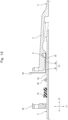
Fig. 10] Fig. 10 is a partial enlarged cross-sectional view of the pipe joint equipped with the ring body, that illustrates a cross section of the interval maintaining part when the ring body is mounted at the proper position. - [
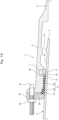
Fig. 11] Fig. 11 is a partial enlarged cross-sectional view of the pipe joint equipped with the ring body, that illustrates a cross section of the ring main body portion when the ring body is mounted at the proper position. - [
Fig. 12] Fig. 12 is a view illustrating a method for joining pipes using the ring body, that illustrates a state when the diameter of a lock ring is expanded and a spigot is inserted in a socket. - [
Fig. 13] Fig. 13 is a view illustrating the method for joining pipes using the ring body, that illustrates a state when the diameter of the lock ring is reduced to cause the lock ring to cling to the outer circumference of the spigot. - [
Fig. 14] Fig. 14 is a view illustrating the method for joining pipes using the ring body, that illustrates a state when the ring body is inserted and is set at the proper position. - [
Fig. 15] Fig. 15 is a partial enlarged cross-sectional view of the pipe joint equipped with the ring body, that illustrates a cross section of the interval maintaining part when the insertion amount of the ring body is insufficient. - [
Fig. 16] Fig. 16 is a cross-sectional view of a pipe joint in a second embodiment of the present invention. - [
Fig. 17] Fig. 17 is a partial enlarged cross-sectional view of the pipe joint equipped with a ring body, that illustrates a state when the ring body is set at the proper position. - [
Fig. 18] Fig. 18 is a partial enlarged cross-sectional view of the pipe joint equipped with the ring body, that illustrates a state when a seal ring is pushed in. - [
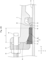
Fig. 19] Fig. 19 is a partial enlarged cross-sectional view of a pipe joint equipped with a ring body in a third embodiment of the present invention, that illustrates a cross section of a gap maintaining part of the ring body. - [
Fig. 20] Fig. 20 is a partial enlarged cross-sectional view of the pipe joint equipped with the ring body, that illustrates a cross section of a ring main body portion of the ring body. - [
Fig. 21] Fig. 21 is a cross-sectional view of a pipe joint equipped with a conventional ring body. - [
Fig. 22] Fig. 22 is a partial enlarged cross-sectional view of the pipe joint equipped with the ring body, that illustrates a state when the ring body is set at the proper position. - [
Fig. 23] Fig. 23 is a partial enlarged cross-sectional view of the pipe joint equipped with the ring body, that illustrates a state when the insertion amount of the ring body is insufficient. - Hereunder, embodiments of the present invention are described with reference to the accompanying drawings.
- As illustrated in
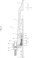
Fig. 1 andFig. 2 , apipe joint 1 has aspigot 3 formed in afirst pipe 2, and asocket 5 formed in asecond pipe 4, with thespigot 3 being inserted into thesocket 5. For example, ductile iron pipes are used for thesepipes - A lock
ring accommodation groove 7 is formed over the entire circumference in the inner circumferential surface of thesocket 5. Alock ring 8 is accommodated in the lockring accommodation groove 7. As illustrated inFig. 3 , thelock ring 8 is a ring having a split structure in which one portion has been cut at a location along the circumferential direction. The diameter of thelock ring 8 is expanded by expanding agap 12 between the cut ends at acut portion 11 using anexpander 13, and thelock ring 8 has elasticity such that its diameter is reduced to return to the original diameter by removing theexpander 13 from thecut portion 11. - As illustrated in
Fig. 1 andFig. 2 , aspigot protrusion 15 is formed over the entire circumference at the outer circumference of thespigot 3. Thespigot protrusion 15 can prevent thespigot 3 from separating from thesocket 5 by thespigot protrusion 15 being caught on thelock ring 8 from the socket inner side in aseparation direction 6 of thespigot 3. - At a location which is closer to the opening end of the
socket 5 than thelock ring 8, aseal ring 19 is provided that is compressed in a piperadial direction 17 to seal a space between an outercircumferential surface 3a of thespigot 3 and the inner circumferential surface of thesocket 5. Theseal ring 19 is a ring made of rubber. - The
socket 5 has, at the inner circumference thereof, asocket sealing surface 21 with which the outer circumferential surface of theseal ring 19 contacts with pressure over the entire circumference, and asocket protrusion 22 that protrudes inward in the pipe radial direction from a deeper portion of thesocket sealing surface 21. - As illustrated in
Fig. 1 andFig. 10 , thesocket sealing surface 21 has a taperedsurface 25 that decreases in diameter gradually from an opening end face 24 of thesocket 5 to the inner side, and an innercircumferential surface 26 that extends to the inner side from the deeper end of the taperedsurface 25. The innercircumferential surface 26 is formed with a uniform inner diameter in apipe axis direction 27 and is parallel to the outercircumferential surface 3a of thespigot 3. - The
socket protrusion 22 is formed in a circular shape over the entire circumference between the innercircumferential surface 26 of thesocket sealing surface 21 and the lockring accommodation groove 7. Thesocket protrusion 22 has afirst end face 22b that extends from the deeper end of the innercircumferential surface 26 of thesocket sealing surface 21 to an innercircumferential surface 22a of thesocket protrusion 22, and asecond end face 22c that extends from the innercircumferential surface 22a to the lockring accommodation groove 7. - The
first end face 22b of thesocket protrusion 22 is a tapered face whose diameter decreases as it approaches the innercircumferential surface 22a of thesocket protrusion 22 from the deeper end of the innercircumferential surface 26 of thesocket sealing surface 21. Further, thesecond end face 22c of thesocket protrusion 22 is a face which faces toward a deeper portion of thesocket 5, and is located at the deeper end of thesocket protrusion 22 in thepipe axis direction 27. The inner diameter of the innercircumferential surface 26 of thesocket sealing surface 21 is set to a larger diameter than the inner diameter of thesocket protrusion 22. - As illustrated in
Fig. 1 andFig. 2 , agland 30 that pushes theseal ring 19 into a deeper portion of thesocket 5 is provided at the opening end part of thesocket 5. Thegland 30 has acontact portion 32 that contacts the opening end face 24 of thesocket 5 in aninsertion direction 31 of theseal ring 19. Thegland 30 is connected to the opening end part of thesocket 5 by a plurality ofbolts 33 and nuts 34. - A
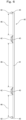
ring body 40 is provided between thelock ring 8 and theseal ring 19 in thepipe axis direction 27. As illustrated inFig. 4 to Fig. 6 , thering body 40 is made of a material that has elasticity, such as resin. Thering body 40 has an annular ringmain body portion 41 that can be inserted between the innercircumferential surface 22a of thesocket protrusion 22 and the outercircumferential surface 3a of thespigot 3, and a plurality ofinterval maintaining parts 42 that can be inserted between the innercircumferential surface 26 of thesocket sealing surface 21 and the outercircumferential surface 3a of thespigot 3. Thering body 40 is a ring having a structure that is split at one location in the circumferential direction, in which any one of theinterval maintaining parts 42 is cut at the center. - As illustrated in
Fig. 7 , the ringmain body portion 41 has a quadrilateral cross section. Further, as illustrated inFig. 4 to Fig. 6 , the plurality ofinterval maintaining parts 42 are integrally provided on the ringmain body portion 41 at predetermined intervals from each other in apipe circumference direction 44. As illustrated inFig. 8 and Fig. 9 , theinterval maintaining part 42 is a protrusion that protrudes from the ringmain body portion 41 at a position toward the socket opening end, and protrudes further outward in the pipe radial direction than the ringmain body portion 41. Theinterval maintaining part 42 has anengagement surface 45 that is caught on thefirst end face 22b of thesocket protrusion 22 in theinsertion direction 31 of thespigot 3. - The
engagement surface 45 is a tapered surface that projects outward in the piperadial direction 17 from the outer circumferential surface of the ringmain body portion 41, and whose diameter increases as it approaches the outer circumferential surface of theinterval maintaining part 42 from the outer circumferential surface of the ringmain body portion 41. - An inner diameter d1 of the
interval maintaining part 42 is the same as an inner diameter d2 of the ringmain body portion 41. An outer diameter D1 of theinterval maintaining part 42 is larger than an outer diameter D2 of the ringmain body portion 41. - An
escape space 46 into which a distal end portion of theseal ring 19 that is compressed can enter is formed at a location which is between oneinterval maintaining part 42 and anotherinterval maintaining part 42 that are adjacent in thepipe circumference direction 44 and which is closer to the socket opening end than the ringmain body portion 41. - As illustrated in
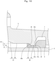
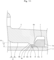
Fig. 10 andFig. 11 , in a state in which theengagement surface 45 of theinterval maintaining part 42 is caught against thefirst end face 22b of thesocket protrusion 22, adeeper end face 41a of the ringmain body portion 41 is positioned closer to the socket opening end than thesecond end face 22c of thesocket protrusion 22. - A method for joining the
first pipe 2 and thesecond pipe 4 with the aforementioned pipe joint 1 is described hereunder. - As illustrated in
Fig. 12 , thering body 40, theseal ring 19, and thegland 30 are externally fitted to thefirst pipe 2 in advance. Further, thelock ring 8 is accommodated in the lockring accommodation groove 7 of thesecond pipe 4. Then, as illustrated inFig. 3 , thegap 12 of thecut portion 11 of thelock ring 8 is expanded using anexpander 13 to thereby expand the diameter of thelock ring 8. Next, as illustrated inFig. 12 , an L-shapeddiameter expansion holder 50 is inserted into thecut portion 11 of thelock ring 8 and theexpander 13 is removed, to thereby maintain thelock ring 8 in the state in which its diameter is expanded. - Thereafter, the
spigot 3 is inserted into thesocket 5, and thespigot protrusion 15 is passed through from a position close to the socket opening end of thelock ring 8 to a deeper portion of thesocket 52. At such time, since thelock ring 8 is maintained in the state in which its diameter is expanded by thediameter expansion holder 50, thespigot protrusion 15 easily passes through the inner circumference of thelock ring 8. - Next, as illustrated in
Fig. 13 , thediameter expansion holder 50 is removed from thecut portion 11 of thelock ring 8 to thereby cause thegap 12 at thecut portion 11 to be returned to its original size by the elasticity of thelock ring 8, and thelock ring 8 decreases in diameter and clings to the outer circumference of thespigot 3. - At such time, if the pipe axis of the
first pipe 2 deviates in the piperadial direction 17 with respect to the pipe axis of thesecond pipe 4, there will be a place where theinterval 52 between the innercircumferential surface 26 of thesocket sealing surface 21 and the outercircumferential surface 3a of thespigot 3 in the piperadial direction 17 becomes narrower than a predetermined size required in order to push in theseal ring 19. Hereinafter, a place where theinterval 52 becomes narrow as described above is referred to as a "narrow place". At a place that is on the opposite side 180° away from the narrow place in thepipe circumference direction 44, theinterval 52 is enlarged to a larger size than the predetermined size. - For example,
Fig. 13 illustrates a state in which a narrow place has arisen at an upper part of thehorizontal pipes interval 52 at a lower part of thepipes - Thereafter, as illustrated in
Fig. 14 , thering body 40 is moved in thepipe axis direction 27 and inserted between thesocket sealing surface 21 and the outercircumferential surface 3a of thespigot 3 from the opening end of thesocket 5, and mounted at the proper position. - By this means, as illustrated in
Fig. 10 andFig. 11 , the ringmain body portion 41 of thering body 40 is inserted between the innercircumferential surface 22a of thesocket protrusion 22 and the outercircumferential surface 3a of thespigot 3. Theengagement surface 45 of thering body 40 is caught on thefirst end face 22b of thesocket protrusion 22. - At such time, the
interval maintaining parts 42 of thering body 40 are inserted between the innercircumferential surface 26 of thesocket sealing surface 21 and the outercircumferential surface 3a of thespigot 3, and thus theinterval 52 between the innercircumferential surface 26 of thesocket sealing surface 21 and the outercircumferential surface 3a of thespigot 3 in the piperadial direction 17 is maintained at a predetermined size required in order to push in theseal ring 19. - By this means, even in a case where a narrow place arises in a state in which the
spigot 3 is inserted into thesocket 5 as illustrated inFig. 13 that is described above, thereafter, by mounting thering body 40 at the proper position as illustrated inFig. 14 that is described above, theinterval 52 between the innercircumferential surface 26 of thesocket sealing surface 21 and the outercircumferential surface 3a of thespigot 3 in the piperadial direction 17 can be maintained at a predetermined size required in order to push in theseal ring 19 over the entire circumference as illustrated inFig. 10 andFig. 11 . - Because the
engagement surface 45 of thering body 40 is caught on thefirst end face 22b of thesocket protrusion 22, thering body 40 is mounted at the proper position, and the position of thering body 40 does not deviate further into a deeper portion of thesocket 5 than the proper position. - Thereafter, the
seal ring 19 is inserted between thesocket sealing surface 21 and the outercircumferential surface 3a of thespigot 3 from the opening end part of thesocket 5, thegland 30 is connected to the opening end part of thesocket 5 using thebolts 33 and the nuts 34, and thebolts 33 and the nuts 34 are tightened until thecontact portion 32 of thegland 30 comes into contact with the opening end face 24 of thesocket 5. - At such time, as described above, because the
interval 52 between the innercircumferential surface 26 of thesocket sealing surface 21 and the outercircumferential surface 3a of thespigot 3 is being maintained at the predetermined size required in order to push in theseal ring 19, when theseal ring 19 is pushed in between thesocket sealing surface 21 and the outercircumferential surface 3a of thespigot 3, theseal ring 19 is not excessively compressed in the piperadial direction 17. Thus, theseal ring 19 can be easily pushed in between thesocket sealing surface 21 and the outercircumferential surface 3a of thespigot 3 from the opening end part of thesocket 5. - Therefore, as illustrated in
Fig. 1 andFig. 2 , by mounting theseal ring 19 when joining thefirst pipe 2 and thesecond pipe 4, thefirst pipe 2 is centered with respect to thesecond pipe 4, and the pipe axis of thefirst pipe 2 coincides with the pipe axis of thesecond pipe 4. In the centered state, a slight clearance is formed approximately uniformly over the entire circumference between the outer circumferential surface of the ringmain body portion 41 of thering body 40 and the innercircumferential surface 22a of thesocket protrusion 22 and between the outer circumferential surface of theinterval maintaining parts 42 and the innercircumferential surface 26 of thesocket sealing surface 21. - In the method for joining the
pipes ring body 40 described above, when thering body 40 is inserted between thesocket sealing surface 21 and the outercircumferential surface 3a of thespigot 3, as illustrated inFig. 15 , in some cases the insertion amount of thering body 40 may be insufficient and consequently the ringmain body portion 41 does not reach the space between the innercircumferential surface 22a of thesocket protrusion 22 and the outercircumferential surface 3a of thespigot 3, and is instead arranged between the innercircumferential surface 26 of thesocket sealing surface 21 and the outercircumferential surface 3a of thespigot 3 at a location further toward the opening end than thesocket protrusion 22. Even in such a case, because theinterval maintaining parts 42 are inserted between the innercircumferential surface 26 of thesocket sealing surface 21 and the outercircumferential surface 3a of thespigot 3, theinterval 52 between the innercircumferential surface 26 of thesocket sealing surface 21 and the outercircumferential surface 3a of thespigot 3 in the piperadial direction 17 is maintained at the predetermined size required in order to push in theseal ring 19. - Therefore, even in a case where the insertion amount of the
ring body 40 is insufficient, when pushing theseal ring 19 in between thesocket sealing surface 21 and the outercircumferential surface 3a of thespigot 3, theseal ring 19 is not excessively compressed in the piperadial direction 17 and theseal ring 19 can be easily pushed in between thesocket sealing surface 21 and the outercircumferential surface 3a of thespigot 3 from the opening end part of thesocket 5. - Even in a case where the insertion amount of the
ring body 40 is insufficient as illustrated inFig. 15 , by pushing in theseal ring 19 between thesocket sealing surface 21 and the outercircumferential surface 3a of thespigot 3, thering body 40 is pushed into a deeper portion of thesocket 5 by theseal ring 19 until the ringmain body portion 41 reaches the space between the innercircumferential surface 22a of thesocket protrusion 22 and the outercircumferential surface 3a of thespigot 3. - As illustrated in
Fig. 10 andFig. 11 , when thering body 40 is mounted at the proper position, theengagement surface 45 of theinterval maintaining part 42 is caught on thefirst end face 22b of thesocket protrusion 22, and thedeeper end face 41a of the ringmain body portion 41 is positioned closer to the socket opening end than thesecond end face 22c of thesocket protrusion 22. Therefore, contact between the ringmain body portion 41 and thelock ring 8 is prevented, and occurrence of damage to the ringmain body portion 41 can be prevented. - In the first embodiment described above, as illustrated in
Fig. 13 , a case where a narrow place arises at an upper part of thehorizontal pipes interval 52 at a lower part of thepipes horizontal pipes interval 52 is enlarged to a larger size than the predetermined size in a region other than the lower part (for example, the upper part) of thepipes - In the foregoing first embodiment, as illustrated in
Fig. 2 , a case where thefirst pipe 2 is joined to thesecond pipe 4 in a straight condition was described. In contrast, in the second embodiment described hereunder, a case is described in which thefirst pipe 2 is bent upward and joined to the horizontalsecond pipe 4 as illustrated inFig. 16 . - As illustrated in
Fig. 14 , thespigot 3 is inserted into thesocket 5, and thereafter thering body 40 is moved in thepipe axis direction 27 and inserted between thesocket sealing surface 21 and the outercircumferential surface 3a of thespigot 3 from the opening end of thesocket 5 and mounted at the proper position. - Thus, as illustrated in
Fig. 10 andFig. 11 , the ringmain body portion 41 of thering body 40 is inserted between the innercircumferential surface 22a of thesocket protrusion 22 and the outercircumferential surface 3a of thespigot 3, and theengagement surface 45 of thering body 40 is caught on thefirst end face 22b of thesocket protrusion 22. - Thereafter, as illustrated in
Fig. 17 , thefirst pipe 2 is bent upward with respect to the horizontalsecond pipe 4. By this means, theinterval 52 between the innercircumferential surface 26 of thesocket sealing surface 21 and the outercircumferential surface 3a of thespigot 3 becomes narrower than the predetermined size at the upper part of thepipes pipes - Thereafter, the
seal ring 19 is pushed in between thesocket sealing surface 21 and the outercircumferential surface 3a of thespigot 3 from the opening end part of thesocket 5. At such time, as illustrated inFig. 18 , even if theseal ring 19 is excessively compressed in the piperadial direction 17 at the upper part of thepipes seal ring 19 enters theescape space 46 of thering body 40 so that a situation in which theseal ring 19 is pushed in insufficiently can be prevented. - Although in the second embodiment a case where the
first pipe 2 is bent upward with respect to the horizontalsecond pipe 4 is described as an example, the same operations and advantageous effects are also obtained in a case where thefirst pipe 2 is bent downwards (or in another direction) with respect to the horizontalsecond pipe 4. - In the foregoing first embodiment, as illustrated in
Fig. 1 , a configuration is adopted so that when thering body 40 is inserted as far as the proper position, a clearance is formed between thering body 40 and theseal ring 19. In contrast, in the third embodiment described hereunder, as illustrated inFig. 19 , a configuration is adopted in which a distance C from the opening end face 24 of thesocket 5 to thesocket protrusion 22 is shortened compared to the first embodiment, so that theseal ring 19 comes in contact with thering body 40 when thering body 40 is inserted as far as the proper position. - In this case, the
seal ring 19 is compressed in the piperadial direction 17, and is also sandwiched between theinterval maintaining parts 42 of thering body 40 and thegland 30 and thereby compressed in thepipe axis direction 27. At such time, as illustrated inFig. 20 , because theescape space 46 is formed in thering body 40, a sufficiently wide space necessary to prevent excessive compression of theseal ring 19 is secured between thesocket sealing surface 21 and the outercircumferential surface 3a of thespigot 3. Accordingly, by the distal end portion of theseal ring 19 entering into theescape space 46 of thering body 40, it is possible to prevent theseal ring 19 from being excessively compressed between thesocket sealing surface 21 and the outercircumferential surface 3a of thespigot 3. - By this means, in addition to preventing excessive compression of the
seal ring 19 as described above, in comparison to the first embodiment, the distance C from the opening end face 24 of thesocket 5 to thesocket protrusion 22 can be shortened, and the length of thesocket 5 in thepipe axis direction 27 can be shortened. - Although in each of the embodiments described above a configuration is adopted in which the
ring body 40 is split at one place, a configuration may also be adopted in which thering body 40 is divided into a plurality of arc-shaped ring pieces, and adjacent ring pieces are connected together with a connecting member to form theannular ring body 40.
Claims (9)
- A ring body which is to be provided in a pipe joint, the pipe joint comprising:a spigot formed in a first pipe;a socket formed in a second pipe;a lock ring accommodation groove formed in an inner circumference of the socket;a lock ring accommodated in the lock ring accommodation groove; anda seal ring which, at a location that is closer to an opening end of the socket than the lock ring, is compressed in a pipe radial direction to seal a space between an outer circumference of the spigot and the inner circumference of the socket,the socket having, at the inner circumference, a socket sealing surface with which an outer circumferential surface of the seal ring contacts with pressure over the entire circumference, and a socket protrusion that protrudes inward in the pipe radial direction from a deeper portion of the socket sealing surface,an inner diameter of the socket sealing surface being larger than an inner diameter of the socket protrusion,a spigot engagement portion being formed at the outer circumference of the spigot, andin a state in which the spigot is inserted in the socket, separation of the spigot from the socket can be prevented by the spigot engagement portion being caught on the lock ring from a deeper portion of the socket in a separation direction of the spigot,the ring body comprising:an annular ring main body portion that can be inserted between an inner circumferential surface of the socket protrusion and an outer circumferential surface of the spigot; anda plurality of interval maintaining parts that can be inserted between the socket sealing surface and the outer circumferential surface of the spigot, whereinthe plurality of interval maintaining parts are provided in the ring main body portion at predetermined intervals in a pipe circumference direction,by the plurality of interval maintaining parts being inserted between the socket sealing surface and the outer circumferential surface of the spigot, the plurality of interval maintaining parts maintain an interval between the socket sealing surface and the outer circumferential surface of the spigot in the pipe radial direction at a predetermined size that allows the seal ring to be pushed in, andan escape space into which a distal end portion of the seal ring that is compressed can enter is formed at a location which is between one interval maintaining part and another interval maintaining part that are adjacent in the pipe circumference direction and which is closer to a socket opening end than the ring main body portion.
- The ring body according to claim 1, whereinan outer diameter of the interval maintaining part is larger than an outer diameter of the ring main body portion,the interval maintaining part has an engagement surface which is caught on the socket protrusion in an insertion direction of the spigot, andthe engagement surface projects outward in the pipe radial direction from an outer circumferential surface of the ring main body portion.
- The ring body according to claim 2, wherein
in a state in which the engagement surface of the interval maintaining part is caught on the socket protrusion, a deeper end of the ring main body portion in a pipe axis direction is positioned closer to the socket opening end than a deeper end of the socket protrusion. - A pipe joint comprising the ring body according to any one of claim 1 to claim 3, the pipe joint having:a spigot formed in a first pipe;a socket formed in a second pipe;a lock ring accommodation groove formed in an inner circumference of the socket;a lock ring accommodated in the lock ring accommodation groove; anda seal ring which, at a location that is closer to an opening end of the socket than the lock ring, is compressed in a pipe radial direction to seal a space between an outer circumference of the spigot and the inner circumference of the socket, whereinthe socket has, at the inner circumference, a socket sealing surface with which an outer circumferential surface of the seal ring contacts with pressure over the entire circumference, and a socket protrusion that protrudes inward in the pipe radial direction from a deeper portion of the socket sealing surface,an inner diameter of the socket sealing surface is larger than an inner diameter of the socket protrusion,a spigot engagement portion is formed at the outer circumference of the spigot,in a state in which the spigot is inserted in the socket, separation of the spigot from the socket can be prevented by the spigot engagement portion being caught on the lock ring from a deeper portion of the socket in a separation direction of the spigot, andthe ring body is provided between the lock ring and the seal ring.
- The pipe joint according to claim 4, wherein
the first pipe is joined in a straight condition to the second pipe. - The pipe joint according to claim 4, wherein
the first pipe is bent and joined to the second pipe. - The pipe joint according to claim 4, wherein
a clearance is formed between the ring body and the seal ring. - The pipe joint according to claim 4, wherein
the seal ring contacts the ring body. - A method for joining pipes using the ring body according to any one of claim 1 to claim 3, comprising:accommodating a lock ring in a lock ring accommodation groove;inserting a spigot into a socket, and passing a spigot engagement portion into a deeper portion of the socket from a position close to a socket opening end of the lock ring;inserting the ring body between a socket sealing surface and an outer circumferential surface of the spigot from an opening end of the socket; andpushing a seal ring in between the socket sealing surface and the outer circumferential surface of the spigot from the opening end of the socket.
Applications Claiming Priority (2)
| Application Number | Priority Date | Filing Date | Title |
|---|---|---|---|
| JP2022103093A JP7745516B2 (en) | 2022-06-28 | 2022-06-28 | Ring body and pipe joining method using ring body |
| PCT/JP2023/023298 WO2024004851A1 (en) | 2022-06-28 | 2023-06-23 | Ring body, pipe joint, and method for joining pipes using said ring body |
Publications (2)
| Publication Number | Publication Date |
|---|---|
| EP4524444A1 true EP4524444A1 (en) | 2025-03-19 |
| EP4524444A4 EP4524444A4 (en) | 2025-06-18 |
Family
ID=89382902
Family Applications (1)
| Application Number | Title | Priority Date | Filing Date |
|---|---|---|---|
| EP23831293.8A Pending EP4524444A4 (en) | 2022-06-28 | 2023-06-23 | RING BODY, PIPE JOINT AND METHOD FOR CONNECTING PIPES USING SAID RING BODY |
Country Status (6)
| Country | Link |
|---|---|
| EP (1) | EP4524444A4 (en) |
| JP (1) | JP7745516B2 (en) |
| CN (1) | CN119404043A (en) |
| CA (1) | CA3256928A1 (en) |
| TW (1) | TW202409463A (en) |
| WO (1) | WO2024004851A1 (en) |
Cited By (1)
| Publication number | Priority date | Publication date | Assignee | Title |
|---|---|---|---|---|
| EP4524443A4 (en) * | 2022-07-01 | 2025-06-25 | Kubota Corporation | PIPE JOINT |
Family Cites Families (12)
| Publication number | Priority date | Publication date | Assignee | Title |
|---|---|---|---|---|
| US5037144A (en) * | 1990-05-02 | 1991-08-06 | Amsted Industries Incorporated | Restrained pipe joint |
| FR2683609B1 (en) * | 1991-11-07 | 1995-01-20 | Pont A Mousson | LOCKED GASKET FOR PIPES. |
| JPH07260059A (en) * | 1994-03-22 | 1995-10-13 | Kubota Corp | Detachment prevention fitting |
| JP3303069B2 (en) * | 1997-05-29 | 2002-07-15 | 株式会社栗本鐵工所 | Captive fittings |
| JP3339673B2 (en) * | 1998-05-29 | 2002-10-28 | 株式会社栗本鐵工所 | Captive fittings |
| CN100373085C (en) * | 2001-10-04 | 2008-03-05 | 东京瓦斯株式会社 | Plug-in fittings |
| JP4212341B2 (en) | 2002-11-15 | 2009-01-21 | 株式会社クボタ | Pipe joint spacer and pipe joint |
| CN103925432B (en) * | 2009-01-27 | 2016-08-24 | 株式会社久保田 | Pipe joint |
| KR20130033633A (en) * | 2011-09-27 | 2013-04-04 | 박강훈 | Pipe connector |
| JP6525636B2 (en) * | 2015-02-26 | 2019-06-05 | 株式会社クボタ | How to connect backup ring, fittings and pipes |
| JP7382203B2 (en) | 2019-10-18 | 2023-11-16 | 株式会社クボタ | Pipe fittings and pipe joining methods |
| JP7393911B2 (en) | 2019-10-18 | 2023-12-07 | 株式会社クボタ | pipe fittings |
-
2022
- 2022-06-28 JP JP2022103093A patent/JP7745516B2/en active Active
-
2023
- 2023-06-23 CA CA3256928A patent/CA3256928A1/en active Pending
- 2023-06-23 EP EP23831293.8A patent/EP4524444A4/en active Pending
- 2023-06-23 CN CN202380048545.7A patent/CN119404043A/en active Pending
- 2023-06-23 WO PCT/JP2023/023298 patent/WO2024004851A1/en not_active Ceased
- 2023-06-27 TW TW112123906A patent/TW202409463A/en unknown
Cited By (1)
| Publication number | Priority date | Publication date | Assignee | Title |
|---|---|---|---|---|
| EP4524443A4 (en) * | 2022-07-01 | 2025-06-25 | Kubota Corporation | PIPE JOINT |
Also Published As
| Publication number | Publication date |
|---|---|
| WO2024004851A1 (en) | 2024-01-04 |
| EP4524444A4 (en) | 2025-06-18 |
| JP7745516B2 (en) | 2025-09-29 |
| CA3256928A1 (en) | 2025-03-19 |
| JP2024003810A (en) | 2024-01-16 |
| TW202409463A (en) | 2024-03-01 |
| CN119404043A (en) | 2025-02-07 |
Similar Documents
| Publication | Publication Date | Title |
|---|---|---|
| EP4043772B1 (en) | Pipe joint, method for joining pipes, and use of a ring body in a pipe joint | |
| US6427309B1 (en) | Method and forming element for producing a press connection between a fitting and a pipe and being inserted into the reception of the fitting | |
| EP2392845B1 (en) | Pipe joint | |
| JP6735123B2 (en) | Pipe joint and pipe joining method | |
| US6173994B1 (en) | Coupling assemblies for providing fluid connection | |
| EP0122509A1 (en) | Restrained pipe joint | |
| US6497433B1 (en) | Coupling assemblies for providing fluid connection | |
| CN108884955B (en) | Pipe joint, separation preventing member, and pipe joining method | |
| US20040155464A1 (en) | Coupling for connection of a tube or hose by pushing-in | |
| CA3256928A1 (en) | Ring body, pipe joint, and method for joining pipes using the ring body | |
| JP2006118712A (en) | Coupling assembly with connection indicator | |
| JP4286004B2 (en) | Pipe joint structure | |
| US20250224054A1 (en) | Gland, pipe joint, and method for joining pipes | |
| JP6764668B2 (en) | Pipe fittings and pipe joining methods | |
| US12442472B2 (en) | Pipe joint, gland, and method for joining pipes | |
| JP6735124B2 (en) | Pipe fitting and separation prevention member | |
| JP2023069093A (en) | Press rings, pipe joints, and methods for joining pipes | |
| JPH07332555A (en) | Detachment prevention fitting | |
| JP7702313B2 (en) | Press ring, pipe joint, and pipe joining method | |
| EP4038303B1 (en) | Crimped end connection for flexible hose |
Legal Events
| Date | Code | Title | Description |
|---|---|---|---|
| STAA | Information on the status of an ep patent application or granted ep patent |
Free format text: STATUS: THE INTERNATIONAL PUBLICATION HAS BEEN MADE |
|
| PUAI | Public reference made under article 153(3) epc to a published international application that has entered the european phase |
Free format text: ORIGINAL CODE: 0009012 |
|
| STAA | Information on the status of an ep patent application or granted ep patent |
Free format text: STATUS: REQUEST FOR EXAMINATION WAS MADE |
|
| 17P | Request for examination filed |
Effective date: 20241209 |
|
| AK | Designated contracting states |
Kind code of ref document: A1 Designated state(s): AL AT BE BG CH CY CZ DE DK EE ES FI FR GB GR HR HU IE IS IT LI LT LU LV MC ME MK MT NL NO PL PT RO RS SE SI SK SM TR |
|
| A4 | Supplementary search report drawn up and despatched |
Effective date: 20250520 |
|
| RIC1 | Information provided on ipc code assigned before grant |
Ipc: F16L 21/04 20060101ALI20250514BHEP Ipc: F16L 21/02 20060101ALI20250514BHEP Ipc: F16L 21/08 20060101AFI20250514BHEP |
|
| DAV | Request for validation of the european patent (deleted) | ||
| DAX | Request for extension of the european patent (deleted) |