EP4524398A1 - Compressor and refrigeration device - Google Patents
Compressor and refrigeration device Download PDFInfo
- Publication number
- EP4524398A1 EP4524398A1 EP23845963.0A EP23845963A EP4524398A1 EP 4524398 A1 EP4524398 A1 EP 4524398A1 EP 23845963 A EP23845963 A EP 23845963A EP 4524398 A1 EP4524398 A1 EP 4524398A1
- Authority
- EP
- European Patent Office
- Prior art keywords
- accumulator
- compressor
- outlet pipe
- center
- hole
- Prior art date
- Legal status (The legal status is an assumption and is not a legal conclusion. Google has not performed a legal analysis and makes no representation as to the accuracy of the status listed.)
- Granted
Links
Images



Classifications
-
- F—MECHANICAL ENGINEERING; LIGHTING; HEATING; WEAPONS; BLASTING
- F04—POSITIVE - DISPLACEMENT MACHINES FOR LIQUIDS; PUMPS FOR LIQUIDS OR ELASTIC FLUIDS
- F04B—POSITIVE-DISPLACEMENT MACHINES FOR LIQUIDS; PUMPS
- F04B39/00—Component parts, details, or accessories, of pumps or pumping systems specially adapted for elastic fluids, not otherwise provided for in, or of interest apart from, groups F04B25/00 - F04B37/00
- F04B39/12—Casings; Cylinders; Cylinder heads; Fluid connections
- F04B39/121—Casings
-
- F—MECHANICAL ENGINEERING; LIGHTING; HEATING; WEAPONS; BLASTING
- F15—FLUID-PRESSURE ACTUATORS; HYDRAULICS OR PNEUMATICS IN GENERAL
- F15B—SYSTEMS ACTING BY MEANS OF FLUIDS IN GENERAL; FLUID-PRESSURE ACTUATORS, e.g. SERVOMOTORS; DETAILS OF FLUID-PRESSURE SYSTEMS, NOT OTHERWISE PROVIDED FOR
- F15B1/00—Installations or systems with accumulators; Supply reservoir or sump assemblies
- F15B1/02—Installations or systems with accumulators
- F15B1/04—Accumulators
-
- F—MECHANICAL ENGINEERING; LIGHTING; HEATING; WEAPONS; BLASTING
- F04—POSITIVE - DISPLACEMENT MACHINES FOR LIQUIDS; PUMPS FOR LIQUIDS OR ELASTIC FLUIDS
- F04B—POSITIVE-DISPLACEMENT MACHINES FOR LIQUIDS; PUMPS
- F04B41/00—Pumping installations or systems specially adapted for elastic fluids
- F04B41/02—Pumping installations or systems specially adapted for elastic fluids having reservoirs
-
- F—MECHANICAL ENGINEERING; LIGHTING; HEATING; WEAPONS; BLASTING
- F04—POSITIVE - DISPLACEMENT MACHINES FOR LIQUIDS; PUMPS FOR LIQUIDS OR ELASTIC FLUIDS
- F04C—ROTARY-PISTON, OR OSCILLATING-PISTON, POSITIVE-DISPLACEMENT MACHINES FOR LIQUIDS; ROTARY-PISTON, OR OSCILLATING-PISTON, POSITIVE-DISPLACEMENT PUMPS
- F04C23/00—Combinations of two or more pumps, each being of rotary-piston or oscillating-piston type, specially adapted for elastic fluids; Pumping installations specially adapted for elastic fluids; Multi-stage pumps specially adapted for elastic fluids
- F04C23/008—Hermetic pumps
-
- F—MECHANICAL ENGINEERING; LIGHTING; HEATING; WEAPONS; BLASTING
- F25—REFRIGERATION OR COOLING; COMBINED HEATING AND REFRIGERATION SYSTEMS; HEAT PUMP SYSTEMS; MANUFACTURE OR STORAGE OF ICE; LIQUEFACTION SOLIDIFICATION OF GASES
- F25B—REFRIGERATION MACHINES, PLANTS OR SYSTEMS; COMBINED HEATING AND REFRIGERATION SYSTEMS; HEAT PUMP SYSTEMS
- F25B31/00—Compressor arrangements
-
- F—MECHANICAL ENGINEERING; LIGHTING; HEATING; WEAPONS; BLASTING
- F25—REFRIGERATION OR COOLING; COMBINED HEATING AND REFRIGERATION SYSTEMS; HEAT PUMP SYSTEMS; MANUFACTURE OR STORAGE OF ICE; LIQUEFACTION SOLIDIFICATION OF GASES
- F25B—REFRIGERATION MACHINES, PLANTS OR SYSTEMS; COMBINED HEATING AND REFRIGERATION SYSTEMS; HEAT PUMP SYSTEMS
- F25B31/00—Compressor arrangements
- F25B31/02—Compressor arrangements of motor-compressor units
-
- F—MECHANICAL ENGINEERING; LIGHTING; HEATING; WEAPONS; BLASTING
- F25—REFRIGERATION OR COOLING; COMBINED HEATING AND REFRIGERATION SYSTEMS; HEAT PUMP SYSTEMS; MANUFACTURE OR STORAGE OF ICE; LIQUEFACTION SOLIDIFICATION OF GASES
- F25B—REFRIGERATION MACHINES, PLANTS OR SYSTEMS; COMBINED HEATING AND REFRIGERATION SYSTEMS; HEAT PUMP SYSTEMS
- F25B43/00—Arrangements for separating or purifying gases or liquids; Arrangements for vaporising the residuum of liquid refrigerant, e.g. by heat
- F25B43/006—Accumulators
-
- F—MECHANICAL ENGINEERING; LIGHTING; HEATING; WEAPONS; BLASTING
- F04—POSITIVE - DISPLACEMENT MACHINES FOR LIQUIDS; PUMPS FOR LIQUIDS OR ELASTIC FLUIDS
- F04C—ROTARY-PISTON, OR OSCILLATING-PISTON, POSITIVE-DISPLACEMENT MACHINES FOR LIQUIDS; ROTARY-PISTON, OR OSCILLATING-PISTON, POSITIVE-DISPLACEMENT PUMPS
- F04C2240/00—Components
- F04C2240/30—Casings or housings
-
- F—MECHANICAL ENGINEERING; LIGHTING; HEATING; WEAPONS; BLASTING
- F04—POSITIVE - DISPLACEMENT MACHINES FOR LIQUIDS; PUMPS FOR LIQUIDS OR ELASTIC FLUIDS
- F04C—ROTARY-PISTON, OR OSCILLATING-PISTON, POSITIVE-DISPLACEMENT MACHINES FOR LIQUIDS; ROTARY-PISTON, OR OSCILLATING-PISTON, POSITIVE-DISPLACEMENT PUMPS
- F04C2240/00—Components
- F04C2240/80—Other components
- F04C2240/804—Accumulators for refrigerant circuits
-
- F—MECHANICAL ENGINEERING; LIGHTING; HEATING; WEAPONS; BLASTING
- F25—REFRIGERATION OR COOLING; COMBINED HEATING AND REFRIGERATION SYSTEMS; HEAT PUMP SYSTEMS; MANUFACTURE OR STORAGE OF ICE; LIQUEFACTION SOLIDIFICATION OF GASES
- F25B—REFRIGERATION MACHINES, PLANTS OR SYSTEMS; COMBINED HEATING AND REFRIGERATION SYSTEMS; HEAT PUMP SYSTEMS
- F25B2500/00—Problems to be solved
- F25B2500/01—Geometry problems, e.g. for reducing size
Definitions
- the present disclosure relates to a compressor and a refrigeration apparatus.
- a compressor having an accumulator with one outlet pipe is known (see, for example, Patent Literature 1).
- the outlet pipe is inserted into a bottom of the accumulator so as to coincide with a center axis of a body of the accumulator.
- a compressor having an accumulator with a plurality of outlet pipes there is a compressor having an accumulator with a plurality of outlet pipes (see, for example, Patent Literature 2 and Patent Literature 3).
- the plurality of outlet pipes are inserted into a bottom of the accumulator so as to make a center of gravity of the insertion positions of the plurality of outlet pipes coincident with a center axis of the accumulator in a top view of the accumulator.
- a horizontal length from a connection portion where the outlet pipes are connected to a compressor body casing to an insertion portion where the outlet pipes are inserted into the accumulator needs to be at least 1/2 of a diameter of the cylindrical accumulator, which makes support rigidity of the accumulator insufficient and makes a structure eigenvalue of the accumulator lower.
- the diameter of the accumulator increases, and the length of the outlet pipes further increases, so that the structure eigenvalue of the accumulator decreases, and the vibration frequency of the compressor becomes more likely to reach the structure eigenvalue of the accumulator due to an increase in the number of rotations of the compressor. It is therefore necessary to increase, particularly in a case where the diameter of the accumulator is increased or the number of rotations of the compressor is increased, the support rigidity of the accumulator.
- the present disclosure proposes a compressor capable of suppressing vibrations of an accumulator, and a refrigeration apparatus including the compressor.
- a compressor of a first aspect of the present disclosure includes:
- the present disclosure makes a distance from a connection position where the outlet pipe is connected to the compressor body casing to the center (centroid) of the portion where the outlet pipe is inserted into the through hole of the accumulator shorter than a corresponding distance of a known compressor in which the outlet pipe is inserted so as to coincide with the center axis of the accumulator, and support rigidity of the accumulator improves accordingly. It is therefore possible to suppress vibrations of the accumulator.
- a compressor of a second aspect of the present disclosure based on the compressor of the first aspect, in the plan view, assuming a virtual straight line passing through a center axis of the compressor body casing and the center axis of the accumulator and a virtual circle centered on a point at which the virtual straight line intersects with an outer peripheral surface of the compressor body casing and having a radius equal to a distance from the point to the center axis of the accumulator, the center or the centroid is located in the virtual circle.
- the present disclosure makes a distance from the connection position where the outlet pipe is connected to the compressor body casing to the center (centroid) of the portion where the outlet pipe is inserted into the through hole of the accumulator shorter to allow an improvement in the support rigidity of the accumulator.
- the center or the centroid is located on the virtual straight line in the plan view.
- the present disclosure allows a further improvement in the support rigidity of the accumulator.
- an end of the accumulator in the center axis direction has a flat portion extending along a radial direction of the accumulator, and the through hole is provided in the flat portion.
- the outlet pipe since the outlet pipe is inserted into the through hole provided in the flat portion of the end of the accumulator, the outlet pipe can be easily connected to the accumulator.
- an end of the accumulator in the center axis direction has a curved portion contiguous with an outer peripheral side surface of the accumulator, and the through hole is provided in the curved portion.
- the outlet pipe is inserted into the through hole provided in the curved portion contiguous with the outer peripheral side surface of the accumulator, as compared with the case where the outlet pipe is inserted into the flat portion, strength of a connection portion between the through hole of the accumulator and the outlet pipe in the curved portion can be increased, a distance from the connection position where the outlet pipe is connected to the compressor body casing to the center (or centroid) of the portion where the outlet pipe is inserted into the through hole of the accumulator can be decreased, rigidity of the connection portion between the accumulator and the outlet pipe can be increased, and the support rigidity of the accumulator can be further improved.
- the outlet pipe has an oil return hole communicating with a space in the accumulator and located near a lowermost portion of the accumulator.
- the present disclosure allows oil accumulated at the bottom of the accumulator to easily return to the compressor body casing.
- a refrigeration apparatus of a seventh aspect of the present disclosure includes a compressor of any one of the first aspect to the sixth aspect.
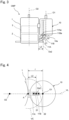
- Fig. 1 is a schematic side view of a compressor CMP of a first embodiment of the present disclosure.
- the compressor CMP is a single-cylinder rotary compressor.
- the compressor CMP of the first embodiment includes a compressor body casing 1, a compression mechanism unit 2 disposed in the compressor body casing 1, and a motor 3 disposed above the compression mechanism unit 2 in the compressor body casing 1 and configured to drive the compression mechanism unit 2 via a shaft (not shown).
- the compressor body casing 1 has a cylindrical outer peripheral surface.
- the compressor CMP includes an accumulator 10 provided outside the compressor body casing 1 and connected to the compression mechanism unit 2 via an outlet pipe 11.
- the accumulator 10 has a cylindrical outer peripheral surface.
- a lower end (end in a center axis direction) of the accumulator 10 has a flat portion 10a extending along a radial direction of the accumulator 10.
- the flat portion 10a is provided with a through hole 21 through which the outlet pipe 11 is inserted.
- the outlet pipe 11 communicates with a space in the accumulator 10 and has an oil return hole 11a located near the lowermost portion of the accumulator 10.
- the oil return hole 11a is spaced about 5 mm to 15 mm apart from a bottom surface of the accumulator 10 in a height direction.
- the compression mechanism unit 2 sucks in refrigerant gas from the accumulator 10 through the outlet pipe 11. Controlling a condenser, an expansion mechanism, and an evaporator (not shown) that constitute an air conditioner as an example of a refrigeration apparatus together with the compressor CMP generates the refrigerant gas.
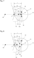
- Fig. 2 is a schematic plan view of the compressor CMP of the first embodiment as viewed from above the accumulator 10.
- a center Ox1 of a portion where the outlet pipe 11 is inserted into the through hole 21 is located closer to the compressor body casing 1 than a center axis O1 of the accumulator 10.
- the center Ox1 of the portion where the outlet pipe 11 is inserted into the through hole 21 is located to the compressor body casing 1 side relative to the center axis O1 of the accumulator 10 in the plan view as viewed from the center axis direction of the accumulator 10.
- This configuration makes a distance L1 from a connection position (point A) where the outlet pipe 11 is connected to the compressor body casing 1 to the center Ox1 of the portion where the outlet pipe 11 is inserted into the through hole 21 of the accumulator 10 shorter than a corresponding distance of the known compressor in which the outlet pipe is inserted so as to coincide with the center axis of the accumulator, and the support rigidity of the accumulator 10 improves accordingly. It is therefore possible to suppress vibrations of the accumulator 10.
- the distance L1 from the connection position (point A) where the outlet pipe 11 is connected to the compressor body casing 1 to the center Ox1 of the portion where the outlet pipe 11 is inserted into the through hole 21 decreases to allow an improvement in the support rigidity of the accumulator 10.
- the center Ox1 of the portion where the outlet pipe 11 is inserted into the through hole 21 of the accumulator 10 is located in the virtual circle VC and on the virtual straight line VL in the plan view, so that the support rigidity of the accumulator 10 further improves.
- the outlet pipe 11 Since the outlet pipe 11 is inserted through the through hole 21 provided in the flat portion 10a of the accumulator 10, the outlet pipe 11 can be easily connected to the accumulator 10.
- Fig. 3 is a schematic side view of a compressor CMP of a second embodiment of the present disclosure.
- the compressor CMP is a two-cylinder rotary compressor.
- the compressor CMP of the second embodiment includes a compressor body casing 1, a compression mechanism unit 2 disposed in the compressor body casing 1, and a motor 3 disposed above the compression mechanism unit 2 in the compressor body casing 1 and configured to drive the compression mechanism unit 2 via a shaft (not shown).
- the compressor body casing 1 has a cylindrical outer peripheral surface.
- the compressor CMP includes an accumulator 10 provided outside the compressor body casing 1 and connected to the compression mechanism unit 2 via two outlet pipes 11A and 11B.
- the accumulator 10 has a cylindrical outer peripheral surface.
- a lower end (end in a center axis direction) of the accumulator 10 has a flat portion 10a extending along a radial direction of the accumulator 10.
- the flat portion 10a is provided with a through hole 21 through which the outlet pipe 11A is inserted.
- the flat portion 10a is further provided with a through hole 22 through which the outlet pipe 11B is inserted.
- the outlet pipe 11A communicates with a space in the accumulator 10 and has an oil return hole 11Aa located near the lowermost portion of the accumulator 10.
- the outlet pipe 11B communicates with the space in the accumulator 10 and has an oil return hole 11Ba located near the lowermost portion of the accumulator 10.
- the oil return holes 11Aa and 11Ba are each spaced about 5 mm to 15 mm apart from a bottom surface of the accumulator 10 in a height direction.
- Fig. 4 is a schematic plan view of the compressor CMP of the second embodiment as viewed from above the accumulator 10.
- a center of gravity Ox2 of a portion where the outlet pipe 11A is inserted into the through hole 21 and a portion where the outlet pipe 11B is inserted into the through hole 22 is located closer to the compressor body casing 1 than a center axis O1 of the accumulator 10.
- the center of gravity Ox2 corresponds to a center of gravity of the center position of each portion, and coordinates of the center of gravity Ox2 are given by an arithmetic mean of center of gravity coordinates of the through holes 21 and 22.
- the center of gravity Ox2 is located in the virtual circle VC.
- the center of gravity Ox2 of the portion where the outlet pipe 11A is inserted into the through hole 21 and the portion where the outlet pipe 11B is inserted into the through hole 22 is located closer to the compressor body casing 1 than the center axis O1 of the accumulator 10.
- This configuration makes a distance L2 from a connection position (point A) where the outlet pipe 11 is connected to the compressor body casing 1 to the center of gravity Ox2 shorter than a corresponding distance of the known compressor in which the center of gravity of the two outlet pipes is located on the center axis of the accumulator, and the support rigidity of the accumulator 10 improves accordingly. It is therefore possible to suppress vibrations of the accumulator 10.
- the distance L2 from the connection position (point A) where the outlet pipe 11 is connected to the compressor body casing 1 to the center of gravity Ox2 decreases to allow an improvement in the support rigidity of the accumulator 10.
- the center of gravity Ox2 is located in the virtual circle VC and on the virtual straight line VL in the plan view, so that the support rigidity of the accumulator 10 further improves.
- the outlet pipe 11A is inserted through the through hole 21 provided in the flat portion 10a of the accumulator 10 and the outlet pipe 11B is inserted through the through hole 22 provided in the flat portion 10a of the accumulator 10, the outlet pipes 11A and 11B can be easily connected to the accumulator 10.
- oil accumulated at a bottom of the accumulator 10 can be easily returned to the compressor body casing 1.
- Fig. 5 is a schematic side view of a compressor CMP of a third embodiment of the present disclosure.
- the compressor CMP is a three-cylinder rotary compressor.
- the compressor CMP includes an accumulator 10 provided outside a compressor body casing 1 and connected to a compression mechanism unit 2 via three outlet pipes 11A, 11B, and 11C.
- the accumulator 10 has a cylindrical outer peripheral surface.
- a lower end (end in a center axis direction) of the accumulator 10 has a flat portion 10a extending along a radial direction of the accumulator 10.
- the flat portion 10a is provided with a through hole 21 through which the outlet pipe 11A is inserted.
- the flat portion 10a is provided with a through hole 22 through which the outlet pipe 11B is inserted.
- the flat portion 10a is provided with a through hole 23 through which the outlet pipe 11C is inserted.
- the outlet pipe 11A communicates with a space in the accumulator 10 and has an oil return hole 11Aa located near the lowermost portion of the accumulator 10.
- the outlet pipe 11B communicates with the space in the accumulator 10 and has an oil return hole 11Ba located near the lowermost portion of the accumulator 10.
- the outlet pipe 11C communicates with the space in the accumulator 10 and has an oil return hole (not shown) located near the lowermost portion of the accumulator 10.
- Fig. 6 is a schematic plan view of the compressor CMP of the third embodiment as viewed from above the accumulator 10.
- a center of gravity Ox3 of a portion where the outlet pipe 11A is inserted into the through hole 21, a portion where the outlet pipe 11B is inserted into the through hole 22, and a portion where the outlet pipe 11C is inserted into the through hole 23 is located closer to the compressor body casing 1 than a center axis O1 of the accumulator 10.
- the center of gravity Ox3 corresponds to a center of gravity of the center position of each portion, and the center of gravity of Ox3 is given by an arithmetic mean of center of gravity coordinates of the through holes 21, 22, and 23.
- the distance L3 from the connection position (point A) where the outlet pipes 11A, 11B, and 11C is connected to the compressor body casing 1 to the center of gravity Ox3 decreases to allow an improvement in the support rigidity of the accumulator 10.
- the center of gravity Ox3 is located in the virtual circle VC and on the virtual straight line VL in the plan view, so that the support rigidity of the accumulator 10 further improves.
- outlet pipes 11A, 11B, and 11C are inserted through the through holes 21, 22, and 23 provided in the flat portion 10a of the accumulator 10, the outlet pipes 11A, 11B, and 11C can be easily connected to the accumulator 10.
- the oil return hole 11Aa communicating with the space in the accumulator 10 is located near the lowermost portion of the accumulator 10
- the oil return hole 11Ba communicating with the space in the accumulator 10 is located near the lowermost portion of the accumulator 10
- the oil return hole of the outlet pipe 11C communicating with the space in the accumulator 10 is located near the lowermost portion of the accumulator 10
- oil accumulated at a bottom of the accumulator 10 can be easily returned to the compressor body casing 1.
- all of the portion where the outlet pipe 11A is inserted into the through hole 21, the portion where the outlet pipe 11B is inserted into the through hole 22, and the portion where the outlet pipe 11C is inserted into the through hole 23 are located in the virtual circle VC; however, the present disclosure is not limited to such a configuration, and it is only required that the center of gravity Ox3 be located in the virtual circle VC.
- Fig. 9 is a schematic side view of a compressor CMP of a fourth embodiment of the present disclosure.
- the compressor CMP of the fourth embodiment has the same configuration as of the compressor CMP of the first embodiment except for the shape of the accumulator 10 and the position where the outlet pipe 11 is inserted.
- the compressor CMP of the fourth embodiment includes an accumulator 10 provided outside a compressor body casing 1 and connected to a compression mechanism unit 2 via an outlet pipe 11.
- the accumulator 10 has a cylindrical outer peripheral surface.
- a lower end (end in a center axis direction) of the accumulator 10 has a flat portion 10a extending along a radial direction of the accumulator 10 and a curved portion 10b contiguous with an outer peripheral side surface and extending between a flat portion 10a and the outer peripheral side surface.
- the curved portion 10b is provided with a through hole 21 through which the outlet pipe 11 is inserted.
- the compressor CMP having the above configuration can increase strength of a connection portion between the through hole 21 of the accumulator 10 and the outlet pipe 11 in the curved portion 10b, decrease a distance L4 from a connection position where the outlet pipe 11 is connected to the compressor body casing 1 to a center Ox4 of the portion where the outlet pipe 11 is inserted into the through hole 21 of the accumulator 10, increase rigidity of the connection portion between the accumulator 10 and the outlet pipe 11, and further improve the support rigidity of the accumulator 10.
- the compressor CMP of the fourth embodiment has effects similar to those of the compressor CMP of the first embodiment.
- Fig. 10 is a schematic side view of a compressor CMP of a fifth embodiment of the present disclosure.
- the compressor CMP is a two-cylinder rotary compressor.
- the compressor CMP includes an accumulator 10 provided outside a compressor body casing 1 and connected to a compression mechanism unit 2 via outlet pipes 11A and 11B.
- the accumulator 10 has a cylindrical outer peripheral surface.
- a lower end (end in a center axis direction) of the accumulator 10 has a flat portion 10a extending along a radial direction of the accumulator 10 and a curved portion 10b contiguous with an outer peripheral side surface and extending between a flat portion 10a and the outer peripheral side surface.
- the curved portion 10b is provided with a through hole 21 through which the outlet pipe 11A is inserted.
- the flat portion 10a is provided with a through hole 22 through which the outlet pipe 11B is inserted.
- the outlet pipe 11A communicates with a space in the accumulator 10 and has an oil return hole 11Aa located near the lowermost portion of the accumulator 10.
- the outlet pipe 11B communicates with the space in the accumulator 10 and has an oil return hole 11Ba located near the lowermost portion of the accumulator 10.
- the oil return holes 11Aa and 11Ba are each spaced about 5 mm to 15 mm apart from a bottom surface of the accumulator 10 in a height direction.
- a center of gravity Ox5 of a portion where the outlet pipe 11A is inserted into the through hole 21 and a portion where the outlet pipe 11B is inserted into the through hole 22 is located closer to the compressor body casing 1 than a center axis O1 of the accumulator 10.
- the center of gravity Ox5 is located in the virtual circle VC.
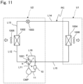
- Fig. 11 is a circuit diagram of an air conditioner as an example of a refrigeration apparatus including a refrigerant circuit using a compressor CMP of a sixth embodiment of the present disclosure. Any one of the compressors CMP of the first to fifth embodiments is used for the refrigerant circuit RC.
- the air conditioner of the sixth embodiment includes an indoor unit U1 installed in an indoor space to be air-conditioned and an outdoor unit U2 installed outdoors.
- the indoor unit U1 of the air conditioner includes an indoor heat exchanger 1004 having one end connected to a refrigerant pipe L14 (connection pipe) and the other end connected to a refrigerant pipe L15 (connection pipe), and an indoor fan 1006 that supplies air to the indoor heat exchanger 1004.
- the indoor fan 1006 blows out, toward the indoor space, air having temperature and the like adjusted by the indoor heat exchanger 1004.
- the outdoor unit U2 of the air conditioner includes the compressor CMP, a four-way switching valve 1001, an outdoor heat exchanger 1002, an expansion valve 1003 as an example of an expansion mechanism, the accumulator 10, an outdoor fan 1005 that sends air to the outdoor heat exchanger 1002.
- the compressor CMP has a discharge side connected to a first port a of the four-way switching valve 1001 via a refrigerant pipe L11.
- the four-way switching valve 1001 has a second port b connected to one end of the outdoor heat exchanger 1002 via a refrigerant pipe L12.
- the outdoor heat exchanger 1002 has the other end connected to one end of the expansion valve 1003 via a refrigerant pipe L13, and the expansion valve 1003 has the other end connected to one end of the refrigerant pipe L14 (connection pipe).
- the refrigerant pipe L15 (connection pipe) has one end connected to a third port c of the four-way switching valve 1001.
- the four-way switching valve 1001 has a fourth port d connected to a suction side of the compressor CMP via a refrigerant pipe L16, the accumulator 10, and the outlet pipe 11.
- the refrigerant flowing through the outdoor heat exchanger 1002 exchanges heat with air sucked by the outdoor fan 1005.
- the expansion valve 1003 is, for example, an electric valve whose opening degree is adjustable, and the opening degree changes according to a signal from a control device (not shown).
- the compression mechanism unit 2 and the accumulator 10 are connected via one outlet pipe 11, but in a case where the compressor CMP of one of the second to fifth embodiments is used, the compression mechanism unit 2 and the accumulator 10 are connected via two outlet pipes 11A and 11B or connected via three outlet pipes 11A, 11B, and 11C.
- the refrigerant circuit RC of the air conditioner includes the indoor heat exchanger 1004, the compressor CMP, the four-way switching valve 1001, the outdoor heat exchanger 1002, the expansion valve 1003, the accumulator 10, the refrigerant pipes L11 to L16, and the outlet pipe 11. Accordingly, an annular refrigerant circuit RC is configured.
- the four-way switching valve 1001 is switched to a switching position indicated by the solid line for cooling operation and is switched to a switching position indicated by the dotted line for heating operation to drive the compressor CMP, so as to cause the refrigerant to circulate through the refrigerant circuit RC.
- the air conditioner having the above configuration, it is possible to achieve, by providing the refrigerant circuit RC using the compressor CMP, an air conditioner with vibrations of the compressor CMP suppressed.
- the air conditioner has been described as the refrigeration apparatus, but the refrigeration apparatus including the refrigerant circuit RC using the compressor CMP is not limited to the air conditioner, and may be a refrigeration apparatus having another configuration.
- the rotary compressor has been described; alternatively, the present disclosure may be applied to a compressor having another configuration such as a swing compressor.
- a single-cylinder compressor with one outlet pipe has been described
- a two-cylinder compressor with two outlet pipes has been described
- a three-cylinder compressor with three outlet pipes has been described; alternatively, the number of cylinders and the number of outlet pipes may be different.
- the present disclosure may be applied to a two-cylinder compressor with one outlet pipe.
- the number of outlet pipes may be four or more.
- the cross section of the outlet pipe and the shape of the through hole are not limited to a perfect circle, and may be, for example, an ellipse.
Landscapes
- Engineering & Computer Science (AREA)
- Mechanical Engineering (AREA)
- General Engineering & Computer Science (AREA)
- Physics & Mathematics (AREA)
- Thermal Sciences (AREA)
- Fluid Mechanics (AREA)
- Chemical & Material Sciences (AREA)
- Analytical Chemistry (AREA)
- Power Engineering (AREA)
- Compressor (AREA)
- Applications Or Details Of Rotary Compressors (AREA)
Abstract
Description
- The present disclosure relates to a compressor and a refrigeration apparatus.
- A compressor having an accumulator with one outlet pipe is known (see, for example, Patent Literature 1). In such a compressor, the outlet pipe is inserted into a bottom of the accumulator so as to coincide with a center axis of a body of the accumulator.
- Further, as another known compressor, there is a compressor having an accumulator with a plurality of outlet pipes (see, for example,
Patent Literature 2 and Patent Literature 3). In such a compressor with the plurality of outlet pipes, the plurality of outlet pipes are inserted into a bottom of the accumulator so as to make a center of gravity of the insertion positions of the plurality of outlet pipes coincident with a center axis of the accumulator in a top view of the accumulator. -
- Patent Literature 1:
WO 2020/235076 A - Patent Literature 2:
JP 64-44388 Y - Patent Literature 3:
WO 2019/142408 A - For the above-described compressor, a horizontal length from a connection portion where the outlet pipes are connected to a compressor body casing to an insertion portion where the outlet pipes are inserted into the accumulator needs to be at least 1/2 of a diameter of the cylindrical accumulator, which makes support rigidity of the accumulator insufficient and makes a structure eigenvalue of the accumulator lower. This leads to a problem where a vibration frequency of an integer multiple of the number of rotations of the compressor becomes more likely to reach the structure eigenvalue of the accumulator, and vibrations of the accumulator increase accordingly.
- In particular, as the capacity of the compressor having the above configuration increases, the diameter of the accumulator increases, and the length of the outlet pipes further increases, so that the structure eigenvalue of the accumulator decreases, and the vibration frequency of the compressor becomes more likely to reach the structure eigenvalue of the accumulator due to an increase in the number of rotations of the compressor. It is therefore necessary to increase, particularly in a case where the diameter of the accumulator is increased or the number of rotations of the compressor is increased, the support rigidity of the accumulator.
- The present disclosure proposes a compressor capable of suppressing vibrations of an accumulator, and a refrigeration apparatus including the compressor.
- A compressor of a first aspect of the present disclosure includes:
- a compressor body casing;
- a compression mechanism unit provided in the compressor body casing; and
- an accumulator provided outside the compressor body casing and connected to the compression mechanism unit via an outlet pipe, the accumulator having a through hole through which the outlet pipe is inserted,
- in which, in a plan view as viewed from a center axis direction of the accumulator, a center or a centroid of a portion where the outlet pipe is inserted into the through hole is located closer to the compressor body casing than a center axis of the accumulator.
- The present disclosure makes a distance from a connection position where the outlet pipe is connected to the compressor body casing to the center (centroid) of the portion where the outlet pipe is inserted into the through hole of the accumulator shorter than a corresponding distance of a known compressor in which the outlet pipe is inserted so as to coincide with the center axis of the accumulator, and support rigidity of the accumulator improves accordingly. It is therefore possible to suppress vibrations of the accumulator.
- In a compressor of a second aspect of the present disclosure based on the compressor of the first aspect, in the plan view, assuming a virtual straight line passing through a center axis of the compressor body casing and the center axis of the accumulator and a virtual circle centered on a point at which the virtual straight line intersects with an outer peripheral surface of the compressor body casing and having a radius equal to a distance from the point to the center axis of the accumulator, the center or the centroid is located in the virtual circle.
- The present disclosure makes a distance from the connection position where the outlet pipe is connected to the compressor body casing to the center (centroid) of the portion where the outlet pipe is inserted into the through hole of the accumulator shorter to allow an improvement in the support rigidity of the accumulator.
- In a compressor of a third aspect of the present disclosure based on the compressor of the second aspect, the center or the centroid is located on the virtual straight line in the plan view.
- The present disclosure allows a further improvement in the support rigidity of the accumulator.
- In a compressor of a fourth aspect of the present disclosure based on the compressor of any one of the first aspect to the third aspect, an end of the accumulator in the center axis direction has a flat portion extending along a radial direction of the accumulator, and the through hole is provided in the flat portion.
- According to the present disclosure, since the outlet pipe is inserted into the through hole provided in the flat portion of the end of the accumulator, the outlet pipe can be easily connected to the accumulator.
- In a compressor of a fifth aspect of the present disclosure based on the compressor of any one of the first aspect to the third aspect, an end of the accumulator in the center axis direction has a curved portion contiguous with an outer peripheral side surface of the accumulator, and the through hole is provided in the curved portion.
- According to the present disclosure, since the outlet pipe is inserted into the through hole provided in the curved portion contiguous with the outer peripheral side surface of the accumulator, as compared with the case where the outlet pipe is inserted into the flat portion, strength of a connection portion between the through hole of the accumulator and the outlet pipe in the curved portion can be increased, a distance from the connection position where the outlet pipe is connected to the compressor body casing to the center (or centroid) of the portion where the outlet pipe is inserted into the through hole of the accumulator can be decreased, rigidity of the connection portion between the accumulator and the outlet pipe can be increased, and the support rigidity of the accumulator can be further improved.
- In a compressor of a sixth aspect of the present disclosure based on the compressor of any one of the first aspect to the fifth aspect, the outlet pipe has an oil return hole communicating with a space in the accumulator and located near a lowermost portion of the accumulator.
- The present disclosure allows oil accumulated at the bottom of the accumulator to easily return to the compressor body casing.
- A refrigeration apparatus of a seventh aspect of the present disclosure includes a compressor of any one of the first aspect to the sixth aspect.
- According to the present disclosure, it is possible to achieve a low-noise refrigeration apparatus by including a compressor capable of suppressing vibrations of an accumulator.
-
-
Fig. 1 is a schematic side view of a compressor of a first embodiment of the present disclosure. -
Fig. 2 is a schematic plan view of the compressor of the first embodiment as viewed from above an accumulator. -
Fig. 3 is a schematic side view of a compressor of a second embodiment of the present disclosure. -
Fig. 4 is a schematic plan view of the compressor of the second embodiment as viewed from above an accumulator. -
Fig. 5 is a schematic side view of a compressor of a third embodiment of the present disclosure. -
Fig. 6 is a schematic plan view of the compressor of the third embodiment as viewed from above an accumulator. -
Fig. 7 is a schematic plan view of a compressor of a first modification as viewed from above an accumulator. -
Fig. 8 is a schematic plan view of a compressor of a second modification as viewed from above an accumulator. -
Fig. 9 is a schematic side view of a compressor of a fourth embodiment of the present disclosure. -
Fig. 10 is a schematic side view of a compressor of a fifth embodiment of the present disclosure. -
Fig. 11 is a circuit diagram of an air conditioner as an example of a refrigeration apparatus including a refrigerant circuit using a compressor of a sixth embodiment of the present disclosure. - Hereinafter, embodiments will be described. Note that, in the drawings, the same reference numerals represent the same or corresponding parts. In addition, the dimensions on the drawings, such as lengths, widths, thicknesses, and depths, are appropriately changed from actual scales for clarity and simplification of the drawings, and do not represent actual relative dimensions.
-
Fig. 1 is a schematic side view of a compressor CMP of a first embodiment of the present disclosure. The compressor CMP is a single-cylinder rotary compressor. - As shown in
Fig. 1 , the compressor CMP of the first embodiment includes acompressor body casing 1, acompression mechanism unit 2 disposed in thecompressor body casing 1, and amotor 3 disposed above thecompression mechanism unit 2 in thecompressor body casing 1 and configured to drive thecompression mechanism unit 2 via a shaft (not shown). Thecompressor body casing 1 has a cylindrical outer peripheral surface. - The compressor CMP includes an
accumulator 10 provided outside thecompressor body casing 1 and connected to thecompression mechanism unit 2 via anoutlet pipe 11. Theaccumulator 10 has a cylindrical outer peripheral surface. A lower end (end in a center axis direction) of theaccumulator 10 has aflat portion 10a extending along a radial direction of theaccumulator 10. Theflat portion 10a is provided with athrough hole 21 through which theoutlet pipe 11 is inserted. - The
outlet pipe 11 communicates with a space in theaccumulator 10 and has anoil return hole 11a located near the lowermost portion of theaccumulator 10. Theoil return hole 11a is spaced about 5 mm to 15 mm apart from a bottom surface of theaccumulator 10 in a height direction. - The
compression mechanism unit 2 sucks in refrigerant gas from theaccumulator 10 through theoutlet pipe 11. Controlling a condenser, an expansion mechanism, and an evaporator (not shown) that constitute an air conditioner as an example of a refrigeration apparatus together with the compressor CMP generates the refrigerant gas. -
Fig. 2 is a schematic plan view of the compressor CMP of the first embodiment as viewed from above theaccumulator 10. - As shown in
Fig. 2 , in the plan view as viewed from above (the center axis direction of) of theaccumulator 10, a center Ox1 of a portion where theoutlet pipe 11 is inserted into the throughhole 21 is located closer to thecompressor body casing 1 than a center axis O1 of theaccumulator 10. - In the plan view, assuming a virtual straight line VL passing through a center axis O2 of the
compressor body casing 1 and the center axis O1 of theaccumulator 10 and a virtual circle VC centered on a point A at which the virtual straight line VL intersects with the outer peripheral surface of thecompressor body casing 1 and having a radius r equal to a distance from the point A to the center axis O1 of theaccumulator 10, the center Ox1 of the portion where theoutlet pipe 11 is inserted into the throughhole 21 is located in the virtual circle VC. - In the compressor CMP having the above configuration, the center Ox1 of the portion where the
outlet pipe 11 is inserted into the throughhole 21 is located to thecompressor body casing 1 side relative to the center axis O1 of theaccumulator 10 in the plan view as viewed from the center axis direction of theaccumulator 10. This configuration makes a distance L1 from a connection position (point A) where theoutlet pipe 11 is connected to thecompressor body casing 1 to the center Ox1 of the portion where theoutlet pipe 11 is inserted into the throughhole 21 of theaccumulator 10 shorter than a corresponding distance of the known compressor in which the outlet pipe is inserted so as to coincide with the center axis of the accumulator, and the support rigidity of theaccumulator 10 improves accordingly. It is therefore possible to suppress vibrations of theaccumulator 10. - Since the center Ox1 of the portion where the
outlet pipe 11 is inserted into the throughhole 21 of theaccumulator 10 is located in the virtual circle VC, the distance L1 from the connection position (point A) where theoutlet pipe 11 is connected to thecompressor body casing 1 to the center Ox1 of the portion where theoutlet pipe 11 is inserted into the throughhole 21 decreases to allow an improvement in the support rigidity of theaccumulator 10. - In the first embodiment, the center Ox1 of the portion where the
outlet pipe 11 is inserted into the throughhole 21 of theaccumulator 10 is located in the virtual circle VC and on the virtual straight line VL in the plan view, so that the support rigidity of theaccumulator 10 further improves. - Since the
outlet pipe 11 is inserted through the throughhole 21 provided in theflat portion 10a of theaccumulator 10, theoutlet pipe 11 can be easily connected to theaccumulator 10. - Since the
oil return hole 11a communicating with the space in theaccumulator 10 is located near the lowermost portion of theaccumulator 10, oil accumulated at a bottom of theaccumulator 10 can be easily returned to thecompressor body casing 1. -
Fig. 3 is a schematic side view of a compressor CMP of a second embodiment of the present disclosure. The compressor CMP is a two-cylinder rotary compressor. - As shown in
Fig. 3 , the compressor CMP of the second embodiment includes acompressor body casing 1, acompression mechanism unit 2 disposed in thecompressor body casing 1, and amotor 3 disposed above thecompression mechanism unit 2 in thecompressor body casing 1 and configured to drive thecompression mechanism unit 2 via a shaft (not shown). Thecompressor body casing 1 has a cylindrical outer peripheral surface. - The compressor CMP includes an
accumulator 10 provided outside thecompressor body casing 1 and connected to thecompression mechanism unit 2 via twooutlet pipes accumulator 10 has a cylindrical outer peripheral surface. A lower end (end in a center axis direction) of theaccumulator 10 has aflat portion 10a extending along a radial direction of theaccumulator 10. Theflat portion 10a is provided with a throughhole 21 through which theoutlet pipe 11A is inserted. Theflat portion 10a is further provided with a throughhole 22 through which theoutlet pipe 11B is inserted. - The
outlet pipe 11A communicates with a space in theaccumulator 10 and has an oil return hole 11Aa located near the lowermost portion of theaccumulator 10. Theoutlet pipe 11B communicates with the space in theaccumulator 10 and has an oil return hole 11Ba located near the lowermost portion of theaccumulator 10. - The oil return holes 11Aa and 11Ba are each spaced about 5 mm to 15 mm apart from a bottom surface of the
accumulator 10 in a height direction. -
Fig. 4 is a schematic plan view of the compressor CMP of the second embodiment as viewed from above theaccumulator 10. - As shown in
Fig. 4 , in the plan view as viewed from above (the center axis direction of) theaccumulator 10, a center of gravity Ox2 of a portion where theoutlet pipe 11A is inserted into the throughhole 21 and a portion where theoutlet pipe 11B is inserted into the throughhole 22 is located closer to thecompressor body casing 1 than a center axis O1 of theaccumulator 10. Here, the center of gravity Ox2 corresponds to a center of gravity of the center position of each portion, and coordinates of the center of gravity Ox2 are given by an arithmetic mean of center of gravity coordinates of the throughholes - In the plan view, assuming a virtual straight line VL passing through a center axis O2 of the
compressor body casing 1 and the center axis O1 of theaccumulator 10 and a virtual circle VC centered on a point A at which the virtual straight line VL intersects with the outer peripheral surface of thecompressor body casing 1 and having a radius r equal to a distance from the point A to the center axis O1 of theaccumulator 10, the center of gravity Ox2 is located in the virtual circle VC. - In the compressor CMP having the above configuration, in the plan view as viewed from the center axis direction of the
accumulator 10, the center of gravity Ox2 of the portion where theoutlet pipe 11A is inserted into the throughhole 21 and the portion where theoutlet pipe 11B is inserted into the throughhole 22 is located closer to thecompressor body casing 1 than the center axis O1 of theaccumulator 10. This configuration makes a distance L2 from a connection position (point A) where theoutlet pipe 11 is connected to thecompressor body casing 1 to the center of gravity Ox2 shorter than a corresponding distance of the known compressor in which the center of gravity of the two outlet pipes is located on the center axis of the accumulator, and the support rigidity of theaccumulator 10 improves accordingly. It is therefore possible to suppress vibrations of theaccumulator 10. - Since the center of gravity Ox2 of the portion where the
outlet pipe 11A is inserted into the throughhole 21 and the portion where theoutlet pipe 11B is inserted into the throughhole 22 is located in the virtual circle VC, the distance L2 from the connection position (point A) where theoutlet pipe 11 is connected to thecompressor body casing 1 to the center of gravity Ox2 decreases to allow an improvement in the support rigidity of theaccumulator 10. - In the second embodiment, the center of gravity Ox2 is located in the virtual circle VC and on the virtual straight line VL in the plan view, so that the support rigidity of the
accumulator 10 further improves. - Since the
outlet pipe 11A is inserted through the throughhole 21 provided in theflat portion 10a of theaccumulator 10 and theoutlet pipe 11B is inserted through the throughhole 22 provided in theflat portion 10a of theaccumulator 10, theoutlet pipes accumulator 10. - Since the oil return hole 11Aa communicating with the space in the
accumulator 10 is located near the lowermost portion of theaccumulator 10, and the oil return hole 11Ba communicating with the space in theaccumulator 10 is located near the lowermost portion of theaccumulator 10, oil accumulated at a bottom of theaccumulator 10 can be easily returned to thecompressor body casing 1. -
Fig. 5 is a schematic side view of a compressor CMP of a third embodiment of the present disclosure. The compressor CMP is a three-cylinder rotary compressor. - The compressor CMP includes an
accumulator 10 provided outside acompressor body casing 1 and connected to acompression mechanism unit 2 via threeoutlet pipes accumulator 10 has a cylindrical outer peripheral surface. A lower end (end in a center axis direction) of theaccumulator 10 has aflat portion 10a extending along a radial direction of theaccumulator 10. Theflat portion 10a is provided with a throughhole 21 through which theoutlet pipe 11A is inserted. Theflat portion 10a is provided with a throughhole 22 through which theoutlet pipe 11B is inserted. Theflat portion 10a is provided with a throughhole 23 through which theoutlet pipe 11C is inserted. - The
outlet pipe 11A communicates with a space in theaccumulator 10 and has an oil return hole 11Aa located near the lowermost portion of theaccumulator 10. Theoutlet pipe 11B communicates with the space in theaccumulator 10 and has an oil return hole 11Ba located near the lowermost portion of theaccumulator 10. Theoutlet pipe 11C communicates with the space in theaccumulator 10 and has an oil return hole (not shown) located near the lowermost portion of theaccumulator 10. - The oil return holes 11Aa and 11Ba and the oil return hole of the
outlet pipe 11C are each spaced about 5 mm to 15 mm apart from a bottom surface of theaccumulator 10 in a height direction. -
Fig. 6 is a schematic plan view of the compressor CMP of the third embodiment as viewed from above theaccumulator 10. - As shown in
Fig. 6 , in the plan view as viewed from above (the center axis direction of) theaccumulator 10, a center of gravity Ox3 of a portion where theoutlet pipe 11A is inserted into the throughhole 21, a portion where theoutlet pipe 11B is inserted into the throughhole 22, and a portion where theoutlet pipe 11C is inserted into the throughhole 23 is located closer to thecompressor body casing 1 than a center axis O1 of theaccumulator 10. Here, the center of gravity Ox3 corresponds to a center of gravity of the center position of each portion, and the center of gravity of Ox3 is given by an arithmetic mean of center of gravity coordinates of the throughholes - In the plan view, assuming a virtual straight line VL passing through a center axis O2 of the
compressor body casing 1 and the center axis O1 of theaccumulator 10 and a virtual circle VC centered on a point A at which the virtual straight line VL intersects with the outer peripheral surface of thecompressor body casing 1 and having a radius r equal to a distance from the point A to the center axis O1 of theaccumulator 10, the center of gravity Ox3 is located in the virtual circle VC. - In the compressor CMP having the above configuration, in the plan view as viewed from the center axis direction of the
accumulator 10, the center of gravity Ox3 of the portion where theoutlet pipe 11A is inserted into the throughhole 21, the portion where theoutlet pipe 11B is inserted into the throughhole 22, and the portion where theoutlet pipe 11C is inserted into the throughhole 23 is located closer to thecompressor body casing 1 than the center axis O1 of theaccumulator 10. This configuration makes a distance L3 from a connection position (point A) where theoutlet pipe 11 is connected to thecompressor body casing 1 to the center of gravity Ox3 shorter than a corresponding distance of the known compressor in which the center of gravity of the plurality of outlet pipes is located on the center axis of the accumulator, and the support rigidity of theaccumulator 10 improves accordingly. It is therefore possible to suppress vibrations of theaccumulator 10. - Since the center of gravity Ox3 of the portion where the
outlet pipe 11A is inserted into the throughhole 21, the portion where theoutlet pipe 11B is inserted into the throughhole 22, and the portion where theoutlet pipe 11C is inserted into the throughhole 23 is located in the virtual circle VC, the distance L3 from the connection position (point A) where theoutlet pipes compressor body casing 1 to the center of gravity Ox3 decreases to allow an improvement in the support rigidity of theaccumulator 10. - In the third embodiment, the center of gravity Ox3 is located in the virtual circle VC and on the virtual straight line VL in the plan view, so that the support rigidity of the
accumulator 10 further improves. - Since the
outlet pipes holes flat portion 10a of theaccumulator 10, theoutlet pipes accumulator 10. - Since the oil return hole 11Aa communicating with the space in the
accumulator 10 is located near the lowermost portion of theaccumulator 10, the oil return hole 11Ba communicating with the space in theaccumulator 10 is located near the lowermost portion of theaccumulator 10, and the oil return hole of theoutlet pipe 11C communicating with the space in theaccumulator 10 is located near the lowermost portion of theaccumulator 10, oil accumulated at a bottom of theaccumulator 10 can be easily returned to thecompressor body casing 1. - In the third embodiment, all of the portion where the
outlet pipe 11A is inserted into the throughhole 21, the portion where theoutlet pipe 11B is inserted into the throughhole 22, and the portion where theoutlet pipe 11C is inserted into the throughhole 23 are located in the virtual circle VC; however, the present disclosure is not limited to such a configuration, and it is only required that the center of gravity Ox3 be located in the virtual circle VC. - For example, as in a first modification shown in
Fig. 7 , even if the portion where theoutlet pipe 11A is inserted into the throughhole 21 is located in the virtual circle VC, and the portion where theoutlet pipe 11B is inserted into the throughhole 22 and the portion where theoutlet pipe 11 C is inserted into the throughhole 23 are located outside the virtual circle VC, it is only required that the center of gravity Ox3 be located in the virtual circle VC. - As in a second modification shown in
Fig. 8 , even if the portion where theoutlet pipe 11A is inserted into the throughhole 21 and the portion where theoutlet pipe 11B is inserted into the throughhole 22 are located in the virtual circle VC, and the portion where theoutlet pipe 11C is inserted into the throughhole 23 is located outside the virtual circle VC, it is only required that the center of gravity Ox3 be located in the virtual circle VC. -
Fig. 9 is a schematic side view of a compressor CMP of a fourth embodiment of the present disclosure. The compressor CMP of the fourth embodiment has the same configuration as of the compressor CMP of the first embodiment except for the shape of theaccumulator 10 and the position where theoutlet pipe 11 is inserted. - As shown in
Fig. 9 , the compressor CMP of the fourth embodiment includes anaccumulator 10 provided outside acompressor body casing 1 and connected to acompression mechanism unit 2 via anoutlet pipe 11. Theaccumulator 10 has a cylindrical outer peripheral surface. - A lower end (end in a center axis direction) of the
accumulator 10 has aflat portion 10a extending along a radial direction of theaccumulator 10 and acurved portion 10b contiguous with an outer peripheral side surface and extending between aflat portion 10a and the outer peripheral side surface. Thecurved portion 10b is provided with a throughhole 21 through which theoutlet pipe 11 is inserted. - The compressor CMP having the above configuration, as compared with the case where the
outlet pipe 11 is inserted into theflat portion 10a, can increase strength of a connection portion between the throughhole 21 of theaccumulator 10 and theoutlet pipe 11 in thecurved portion 10b, decrease a distance L4 from a connection position where theoutlet pipe 11 is connected to thecompressor body casing 1 to a center Ox4 of the portion where theoutlet pipe 11 is inserted into the throughhole 21 of theaccumulator 10, increase rigidity of the connection portion between theaccumulator 10 and theoutlet pipe 11, and further improve the support rigidity of theaccumulator 10. - The compressor CMP of the fourth embodiment has effects similar to those of the compressor CMP of the first embodiment.
-
Fig. 10 is a schematic side view of a compressor CMP of a fifth embodiment of the present disclosure. The compressor CMP is a two-cylinder rotary compressor. - As shown in
Fig. 10 , the compressor CMP includes anaccumulator 10 provided outside acompressor body casing 1 and connected to acompression mechanism unit 2 viaoutlet pipes accumulator 10 has a cylindrical outer peripheral surface. A lower end (end in a center axis direction) of theaccumulator 10 has aflat portion 10a extending along a radial direction of theaccumulator 10 and acurved portion 10b contiguous with an outer peripheral side surface and extending between aflat portion 10a and the outer peripheral side surface. Thecurved portion 10b is provided with a throughhole 21 through which theoutlet pipe 11A is inserted. Theflat portion 10a is provided with a throughhole 22 through which theoutlet pipe 11B is inserted. - The
outlet pipe 11A communicates with a space in theaccumulator 10 and has an oil return hole 11Aa located near the lowermost portion of theaccumulator 10. Theoutlet pipe 11B communicates with the space in theaccumulator 10 and has an oil return hole 11Ba located near the lowermost portion of theaccumulator 10. - The oil return holes 11Aa and 11Ba are each spaced about 5 mm to 15 mm apart from a bottom surface of the
accumulator 10 in a height direction. - In the fifth embodiment, as in the second embodiment, in the plan view as viewed from above (the center axis direction of) the
accumulator 10, a center of gravity Ox5 of a portion where theoutlet pipe 11A is inserted into the throughhole 21 and a portion where theoutlet pipe 11B is inserted into the throughhole 22 is located closer to thecompressor body casing 1 than a center axis O1 of theaccumulator 10. In the plan view, assuming a virtual straight line VL passing through a center axis O2 of thecompressor body casing 1 and the center axis O1 of theaccumulator 10 and a virtual circle VC centered on a point A at which the virtual straight line VL intersects with the outer peripheral surface of thecompressor body casing 1 and having a radius r equal to a distance from the point A to the center axis O1 of theaccumulator 10, the center of gravity Ox5 is located in the virtual circle VC. - In the compressor CMP having the above configuration, a distance L5 from a connection position (point A) where the
outlet pipe 11 is connected to the compressor body casing to the center of gravity Ox5 becomes shorter than a corresponding distance of the known compressor in which the center of gravity of the two outlet pipes is located on the center axis of the accumulator, and the support rigidity of theaccumulator 10 improves accordingly. It is therefore possible to suppress vibrations of theaccumulator 10. - The compressor CMP of the fifth embodiment has effects similar to those of the compressor CMP of the second embodiment.
-
Fig. 11 is a circuit diagram of an air conditioner as an example of a refrigeration apparatus including a refrigerant circuit using a compressor CMP of a sixth embodiment of the present disclosure. Any one of the compressors CMP of the first to fifth embodiments is used for the refrigerant circuit RC. - As shown in
Fig. 11 , the air conditioner of the sixth embodiment includes an indoor unit U1 installed in an indoor space to be air-conditioned and an outdoor unit U2 installed outdoors. - The indoor unit U1 of the air conditioner includes an
indoor heat exchanger 1004 having one end connected to a refrigerant pipe L14 (connection pipe) and the other end connected to a refrigerant pipe L15 (connection pipe), and anindoor fan 1006 that supplies air to theindoor heat exchanger 1004. Theindoor fan 1006 blows out, toward the indoor space, air having temperature and the like adjusted by theindoor heat exchanger 1004. - The outdoor unit U2 of the air conditioner includes the compressor CMP, a four-
way switching valve 1001, anoutdoor heat exchanger 1002, anexpansion valve 1003 as an example of an expansion mechanism, theaccumulator 10, anoutdoor fan 1005 that sends air to theoutdoor heat exchanger 1002. - The compressor CMP has a discharge side connected to a first port a of the four-
way switching valve 1001 via a refrigerant pipe L11. The four-way switching valve 1001 has a second port b connected to one end of theoutdoor heat exchanger 1002 via a refrigerant pipe L12. Theoutdoor heat exchanger 1002 has the other end connected to one end of theexpansion valve 1003 via a refrigerant pipe L13, and theexpansion valve 1003 has the other end connected to one end of the refrigerant pipe L14 (connection pipe). The refrigerant pipe L15 (connection pipe) has one end connected to a third port c of the four-way switching valve 1001. The four-way switching valve 1001 has a fourth port d connected to a suction side of the compressor CMP via a refrigerant pipe L16, theaccumulator 10, and theoutlet pipe 11. - The refrigerant flowing through the
outdoor heat exchanger 1002 exchanges heat with air sucked by theoutdoor fan 1005. - The
expansion valve 1003 is, for example, an electric valve whose opening degree is adjustable, and the opening degree changes according to a signal from a control device (not shown). - Note that, in
Fig. 11 , thecompression mechanism unit 2 and theaccumulator 10 are connected via oneoutlet pipe 11, but in a case where the compressor CMP of one of the second to fifth embodiments is used, thecompression mechanism unit 2 and theaccumulator 10 are connected via twooutlet pipes outlet pipes - Furthermore, the refrigerant circuit RC of the air conditioner includes the
indoor heat exchanger 1004, the compressor CMP, the four-way switching valve 1001, theoutdoor heat exchanger 1002, theexpansion valve 1003, theaccumulator 10, the refrigerant pipes L11 to L16, and theoutlet pipe 11. Accordingly, an annular refrigerant circuit RC is configured. - As shown in
Fig. 11 , the four-way switching valve 1001 is switched to a switching position indicated by the solid line for cooling operation and is switched to a switching position indicated by the dotted line for heating operation to drive the compressor CMP, so as to cause the refrigerant to circulate through the refrigerant circuit RC. - According to the air conditioner having the above configuration, it is possible to achieve, by providing the refrigerant circuit RC using the compressor CMP, an air conditioner with vibrations of the compressor CMP suppressed.
- In the sixth embodiment, the air conditioner has been described as the refrigeration apparatus, but the refrigeration apparatus including the refrigerant circuit RC using the compressor CMP is not limited to the air conditioner, and may be a refrigeration apparatus having another configuration.
- In the first to fifth embodiments, the rotary compressor has been described; alternatively, the present disclosure may be applied to a compressor having another configuration such as a swing compressor.
- In the first and fourth embodiments, a single-cylinder compressor with one outlet pipe has been described, in the second and fifth embodiments, a two-cylinder compressor with two outlet pipes has been described, and in the third embodiment, a three-cylinder compressor with three outlet pipes has been described; alternatively, the number of cylinders and the number of outlet pipes may be different. For example, the present disclosure may be applied to a two-cylinder compressor with one outlet pipe. For example, the number of outlet pipes may be four or more. The cross section of the outlet pipe and the shape of the through hole are not limited to a perfect circle, and may be, for example, an ellipse.
- The foregoing description concerns specific embodiments of the present disclosure; however, the present disclosure is not limited to the first to sixth embodiments, and various modifications and variations may be made within the scope of the present disclosure.
-
- 1 compressor body casing
- 2 compression mechanism unit
- 3 motor
- 10 accumulator
- 10a flat portion
- 10b curved portion
- 11, 11A, 11B, 11C outlet pipe
- 11a, 11Aa, 11Ba oil return hole
- 21, 22, 23 through hole
- A point
- CMP compressor
- O1 center axis of accumulator
- O2 center axis of compressor body casing
- Ox1, Ox4 center
- Ox2, Ox3, Ox5 center of gravity
- RC refrigerant circuit
- VL virtual straight line
- VC virtual circle
Claims (7)
- A compressor (CMP) comprising:a compressor body casing (1);a compression mechanism unit (2) provided in the compressor body casing (1); andan accumulator (10) provided outside the compressor body casing (1) and connected to the compression mechanism unit (2) via at least one outlet pipe (11, 11A, 11B, 11C), the accumulator (10) having at least one through hole (21, 22, 23) through which the outlet pipe (11, 11A, 11B, 11C) is inserted, whereinin a plan view as viewed from a center axis direction of the accumulator (10), a center (Ox1, Ox4) or a center of gravity (Ox2, Ox3, Ox5) of at least one portion where the outlet pipe (11, 11A, 11B, 11C) is inserted into the through hole (21, 22, 23) is located closer to the compressor body casing (1) than a center axis (O1) of the accumulator (10).
- The compressor (CMP) according to claim 1, whereinin the plan view, assuming a virtual straight line (VL) and a virtual circle (VC),the virtual straight line (VL) passing through a center axis (O2) of the compressor body casing (1) and the center axis (O1) of the accumulator (10),the virtual circle (VC) being centered on a point (A) at which the virtual straight line (VL) intersects with an outer peripheral surface of the compressor body casing (1) and having a radius (r) equal to a distance from the point (A) to the center axis (O1) of the accumulator (10),the center (Ox1, Ox4) or the center of gravity (Ox2, Ox3, Ox5) is located in the virtual circle (VC).
- The compressor (CMP) according to claim 2, wherein
the center (Ox1, Ox4) or the center of gravity (Ox2, Ox3, Ox5) is located on the virtual straight line (VL) in the plan view. - The compressor (CMP) according to any one of claims 1 to 3, whereinan end of the accumulator (10) in the center axis direction has a flat portion (10a) extending along a radial direction of the accumulator (10), andthe through hole (21, 22, 23) is provided in the flat portion (10a).
- The compressor (CMP) according to any one of claims 1 to 3, whereinan end of the accumulator (10) in the center axis direction has a curved portion (10b) contiguous with an outer peripheral side surface of the accumulator (10), andthe through hole (21, 22, 23) is provided in the curved portion (10b).
- The compressor (CMP) according to any one of claims 1 to 5, wherein
the outlet pipe (11, 11A, 11B, 11C) has an oil return hole (11a, 11Aa, 11Ba) communicating with a space in the accumulator (10) and located near a lowermost portion of the accumulator (10). - A refrigeration apparatus comprising a compressor (CMP) according to any one of claims 1 to 6.
Applications Claiming Priority (2)
| Application Number | Priority Date | Filing Date | Title |
|---|---|---|---|
| JP2022122029A JP7469687B2 (en) | 2022-07-29 | 2022-07-29 | Compressors and refrigeration equipment |
| PCT/JP2023/018629 WO2024024225A1 (en) | 2022-07-29 | 2023-05-18 | Compressor and refrigeration device |
Publications (3)
| Publication Number | Publication Date |
|---|---|
| EP4524398A1 true EP4524398A1 (en) | 2025-03-19 |
| EP4524398A4 EP4524398A4 (en) | 2025-06-11 |
| EP4524398B1 EP4524398B1 (en) | 2026-02-11 |
Family
ID=89706012
Family Applications (1)
| Application Number | Title | Priority Date | Filing Date |
|---|---|---|---|
| EP23845963.0A Active EP4524398B1 (en) | 2022-07-29 | 2023-05-18 | Compressor and refrigeration apparatus |
Country Status (6)
| Country | Link |
|---|---|
| US (1) | US20250163940A1 (en) |
| EP (1) | EP4524398B1 (en) |
| JP (1) | JP7469687B2 (en) |
| CN (1) | CN119137372A (en) |
| ES (1) | ES3065462T3 (en) |
| WO (1) | WO2024024225A1 (en) |
Families Citing this family (2)
| Publication number | Priority date | Publication date | Assignee | Title |
|---|---|---|---|---|
| JP7832522B2 (en) * | 2024-07-29 | 2026-03-18 | ダイキン工業株式会社 | Compressor unit |
| CN119178258B (en) * | 2024-11-22 | 2025-02-28 | 珠海格力节能环保制冷技术研究中心有限公司 | Liquid accumulator and compressor having the same |
Family Cites Families (13)
| Publication number | Priority date | Publication date | Assignee | Title |
|---|---|---|---|---|
| JPS60142177A (en) * | 1983-12-28 | 1985-07-27 | 松下電器産業株式会社 | Gas-liquid separator for refrigerator |
| JP2009162222A (en) | 2007-12-14 | 2009-07-23 | Daikin Ind Ltd | Hermetic compressor |
| JP5788305B2 (en) | 2011-12-08 | 2015-09-30 | 日立アプライアンス株式会社 | Electric compressor |
| JP5984486B2 (en) | 2012-04-27 | 2016-09-06 | 三菱重工業株式会社 | Rotary compressor |
| TWI654199B (en) | 2013-06-06 | 2019-03-21 | 首威專業聚合物義大利公司 | Method for producing a cyclophosphazene derivative |
| JP2016020657A (en) | 2014-07-15 | 2016-02-04 | パナソニックIpマネジメント株式会社 | Rotary type compressor |
| JP2017125466A (en) | 2016-01-15 | 2017-07-20 | ダイキン工業株式会社 | Accumulator, and compressor including the same |
| JP6913769B2 (en) | 2018-01-18 | 2021-08-04 | 東芝キヤリア株式会社 | Compressor and refrigeration cycle equipment |
| KR101990137B1 (en) * | 2018-01-29 | 2019-09-30 | 엘지전자 주식회사 | Accumulator and Compression Unit including the same |
| JP2019138576A (en) * | 2018-02-13 | 2019-08-22 | 三菱重工サーマルシステムズ株式会社 | Accumulator, and compressor for air conditioning |
| JP6710348B1 (en) | 2019-05-23 | 2020-06-17 | 日立ジョンソンコントロールズ空調株式会社 | Compressor and air conditioner equipped with this compressor |
| CN112747511B (en) * | 2019-10-31 | 2022-03-01 | 广东美的白色家电技术创新中心有限公司 | Liquid storage and oil separation devices, compressor components, heat exchange systems and electrical equipment |
| KR20220144675A (en) | 2021-04-20 | 2022-10-27 | 엘지전자 주식회사 | Accumulator for compressor and compressor with this |
-
2022
- 2022-07-29 JP JP2022122029A patent/JP7469687B2/en active Active
-
2023
- 2023-05-18 ES ES23845963T patent/ES3065462T3/en active Active
- 2023-05-18 CN CN202380038330.7A patent/CN119137372A/en active Pending
- 2023-05-18 EP EP23845963.0A patent/EP4524398B1/en active Active
- 2023-05-18 WO PCT/JP2023/018629 patent/WO2024024225A1/en not_active Ceased
-
2025
- 2025-01-16 US US19/025,102 patent/US20250163940A1/en active Pending
Also Published As
| Publication number | Publication date |
|---|---|
| US20250163940A1 (en) | 2025-05-22 |
| EP4524398A4 (en) | 2025-06-11 |
| CN119137372A (en) | 2024-12-13 |
| WO2024024225A1 (en) | 2024-02-01 |
| JP7469687B2 (en) | 2024-04-17 |
| JP2024018598A (en) | 2024-02-08 |
| EP4524398B1 (en) | 2026-02-11 |
| ES3065462T3 (en) | 2026-05-06 |
Similar Documents
| Publication | Publication Date | Title |
|---|---|---|
| EP4524398B1 (en) | Compressor and refrigeration apparatus | |
| CN112119224B (en) | Centrifugal blower, blower device, air conditioner, and refrigeration cycle device | |
| JP7258099B2 (en) | Air conditioning equipment and refrigeration cycle equipment | |
| CN109247023B (en) | Centrifugal blower, air conditioning device and refrigeration cycle device | |
| JP5295321B2 (en) | Blower, outdoor unit and refrigeration cycle apparatus | |
| WO2020202676A1 (en) | Compressor and air-conditioner | |
| JP5791276B2 (en) | Blower, outdoor unit and refrigeration cycle apparatus | |
| JPWO2020044540A1 (en) | Centrifugal blower, blower, air conditioner and refrigeration cycle device | |
| CN1657782A (en) | Compressor suction pipe structure | |
| US11802721B2 (en) | Heat source unit and scroll compressor | |
| CN117043519A (en) | air conditioning unit | |
| KR20200043847A (en) | Air conditioner and orifice applied to it | |
| JP6380515B2 (en) | Gas-liquid separator and air conditioner equipped with the same | |
| WO2015166581A1 (en) | Air blower, outdoor unit, and refrigeration cycle device | |
| KR102140064B1 (en) | Air conditioner | |
| KR102652240B1 (en) | Air conditioner | |
| WO2018168707A1 (en) | Double-suction centrifugal fan | |
| WO2023286208A1 (en) | Indoor unit and air conditioner | |
| JP6545424B1 (en) | Air conditioner | |
| EP3495752B1 (en) | Air conditioner | |
| JP2013079595A (en) | Fan, outdoor unit and refrigerating cycle device | |
| JP2004245487A (en) | Condensing pressure control device for refrigeration equipment | |
| KR20260050808A (en) | Axial flow fan and air conditioner including the same | |
| KR100854324B1 (en) | Ceiling air conditioners | |
| KR20260050809A (en) | Axial flow fan and air conditioner including the same |
Legal Events
| Date | Code | Title | Description |
|---|---|---|---|
| STAA | Information on the status of an ep patent application or granted ep patent |
Free format text: STATUS: THE INTERNATIONAL PUBLICATION HAS BEEN MADE |
|
| PUAI | Public reference made under article 153(3) epc to a published international application that has entered the european phase |
Free format text: ORIGINAL CODE: 0009012 |
|
| STAA | Information on the status of an ep patent application or granted ep patent |
Free format text: STATUS: REQUEST FOR EXAMINATION WAS MADE |
|
| 17P | Request for examination filed |
Effective date: 20241211 |
|
| AK | Designated contracting states |
Kind code of ref document: A1 Designated state(s): AL AT BE BG CH CY CZ DE DK EE ES FI FR GB GR HR HU IE IS IT LI LT LU LV MC ME MK MT NL NO PL PT RO RS SE SI SK SM TR |
|
| A4 | Supplementary search report drawn up and despatched |
Effective date: 20250509 |
|
| RIC1 | Information provided on ipc code assigned before grant |
Ipc: F04B 39/12 20060101ALI20250502BHEP Ipc: F25B 43/00 20060101ALI20250502BHEP Ipc: F04B 41/02 20060101ALI20250502BHEP Ipc: F25B 31/00 20060101ALI20250502BHEP Ipc: F04C 29/12 20060101ALI20250502BHEP Ipc: F04B 39/00 20060101AFI20250502BHEP |
|
| P01 | Opt-out of the competence of the unified patent court (upc) registered |
Free format text: CASE NUMBER: UPC_APP_3796_4524398/2025 Effective date: 20250820 |
|
| GRAP | Despatch of communication of intention to grant a patent |
Free format text: ORIGINAL CODE: EPIDOSNIGR1 |
|
| STAA | Information on the status of an ep patent application or granted ep patent |
Free format text: STATUS: GRANT OF PATENT IS INTENDED |
|
| DAV | Request for validation of the european patent (deleted) | ||
| DAX | Request for extension of the european patent (deleted) | ||
| RIC1 | Information provided on ipc code assigned before grant |
Ipc: F04B 39/00 20060101AFI20251002BHEP Ipc: F04B 41/02 20060101ALI20251002BHEP Ipc: F04B 39/12 20060101ALI20251002BHEP Ipc: F04C 29/12 20060101ALI20251002BHEP Ipc: F04C 23/00 20060101ALI20251002BHEP Ipc: F25B 31/00 20060101ALI20251002BHEP Ipc: F25B 43/00 20060101ALI20251002BHEP |
|
| INTG | Intention to grant announced |
Effective date: 20251016 |
|
| GRAS | Grant fee paid |
Free format text: ORIGINAL CODE: EPIDOSNIGR3 |
|
| GRAA | (expected) grant |
Free format text: ORIGINAL CODE: 0009210 |
|
| STAA | Information on the status of an ep patent application or granted ep patent |
Free format text: STATUS: THE PATENT HAS BEEN GRANTED |
|
| AK | Designated contracting states |
Kind code of ref document: B1 Designated state(s): AL AT BE BG CH CY CZ DE DK EE ES FI FR GB GR HR HU IE IS IT LI LT LU LV MC ME MK MT NL NO PL PT RO RS SE SI SK SM TR |
|
| REG | Reference to a national code |
Ref country code: CH Ref legal event code: F10 Free format text: ST27 STATUS EVENT CODE: U-0-0-F10-F00 (AS PROVIDED BY THE NATIONAL OFFICE) Effective date: 20260211 Ref country code: GB Ref legal event code: FG4D |
|
| REG | Reference to a national code |
Ref country code: DE Ref legal event code: R096 Ref document number: 602023012008 Country of ref document: DE |
|
| REG | Reference to a national code |
Ref country code: IE Ref legal event code: FG4D |
|
| REG | Reference to a national code |
Ref country code: ES Ref legal event code: FG2A Ref document number: 3065462 Country of ref document: ES Kind code of ref document: T3 Effective date: 20260506 |
|
| REG | Reference to a national code |
Ref country code: NL Ref legal event code: MP Effective date: 20260211 |
|
| PG25 | Lapsed in a contracting state [announced via postgrant information from national office to epo] |
Ref country code: RS Free format text: LAPSE BECAUSE OF FAILURE TO SUBMIT A TRANSLATION OF THE DESCRIPTION OR TO PAY THE FEE WITHIN THE PRESCRIBED TIME-LIMIT Effective date: 20260511 |
|
| PG25 | Lapsed in a contracting state [announced via postgrant information from national office to epo] |
Ref country code: PL Free format text: LAPSE BECAUSE OF FAILURE TO SUBMIT A TRANSLATION OF THE DESCRIPTION OR TO PAY THE FEE WITHIN THE PRESCRIBED TIME-LIMIT Effective date: 20260211 |
|
| PG25 | Lapsed in a contracting state [announced via postgrant information from national office to epo] |
Ref country code: GR Free format text: LAPSE BECAUSE OF FAILURE TO SUBMIT A TRANSLATION OF THE DESCRIPTION OR TO PAY THE FEE WITHIN THE PRESCRIBED TIME-LIMIT Effective date: 20260512 |
|
| PGFP | Annual fee paid to national office [announced via postgrant information from national office to epo] |
Ref country code: IT Payment date: 20260601 Year of fee payment: 4 |
|
| REG | Reference to a national code |
Ref country code: LT Ref legal event code: MG9D |
|
| PG25 | Lapsed in a contracting state [announced via postgrant information from national office to epo] |
Ref country code: LT Free format text: LAPSE BECAUSE OF FAILURE TO SUBMIT A TRANSLATION OF THE DESCRIPTION OR TO PAY THE FEE WITHIN THE PRESCRIBED TIME-LIMIT Effective date: 20260211 |
|
| PGFP | Annual fee paid to national office [announced via postgrant information from national office to epo] |
Ref country code: DE Payment date: 20260522 Year of fee payment: 4 |
|
| PG25 | Lapsed in a contracting state [announced via postgrant information from national office to epo] |
Ref country code: NO Free format text: LAPSE BECAUSE OF FAILURE TO SUBMIT A TRANSLATION OF THE DESCRIPTION OR TO PAY THE FEE WITHIN THE PRESCRIBED TIME-LIMIT Effective date: 20260511 |
|
| PG25 | Lapsed in a contracting state [announced via postgrant information from national office to epo] |
Ref country code: SE Free format text: LAPSE BECAUSE OF FAILURE TO SUBMIT A TRANSLATION OF THE DESCRIPTION OR TO PAY THE FEE WITHIN THE PRESCRIBED TIME-LIMIT Effective date: 20260211 Ref country code: FI Free format text: LAPSE BECAUSE OF FAILURE TO SUBMIT A TRANSLATION OF THE DESCRIPTION OR TO PAY THE FEE WITHIN THE PRESCRIBED TIME-LIMIT Effective date: 20260211 Ref country code: AT Free format text: LAPSE BECAUSE OF FAILURE TO SUBMIT A TRANSLATION OF THE DESCRIPTION OR TO PAY THE FEE WITHIN THE PRESCRIBED TIME-LIMIT Effective date: 20260211 |
|
| REG | Reference to a national code |
Ref country code: AT Ref legal event code: MK05 Ref document number: 1885843 Country of ref document: AT Kind code of ref document: T Effective date: 20260211 |
|
| PG25 | Lapsed in a contracting state [announced via postgrant information from national office to epo] |
Ref country code: HR Free format text: LAPSE BECAUSE OF FAILURE TO SUBMIT A TRANSLATION OF THE DESCRIPTION OR TO PAY THE FEE WITHIN THE PRESCRIBED TIME-LIMIT Effective date: 20260211 |
|
| PG25 | Lapsed in a contracting state [announced via postgrant information from national office to epo] |
Ref country code: IS Free format text: LAPSE BECAUSE OF FAILURE TO SUBMIT A TRANSLATION OF THE DESCRIPTION OR TO PAY THE FEE WITHIN THE PRESCRIBED TIME-LIMIT Effective date: 20260611 Ref country code: PT Free format text: LAPSE BECAUSE OF FAILURE TO SUBMIT A TRANSLATION OF THE DESCRIPTION OR TO PAY THE FEE WITHIN THE PRESCRIBED TIME-LIMIT Effective date: 20260611 |
|
| PG25 | Lapsed in a contracting state [announced via postgrant information from national office to epo] |
Ref country code: NL Free format text: LAPSE BECAUSE OF FAILURE TO SUBMIT A TRANSLATION OF THE DESCRIPTION OR TO PAY THE FEE WITHIN THE PRESCRIBED TIME-LIMIT Effective date: 20260211 |
|
| PGFP | Annual fee paid to national office [announced via postgrant information from national office to epo] |
Ref country code: FR Payment date: 20260526 Year of fee payment: 4 |
|
| PG25 | Lapsed in a contracting state [announced via postgrant information from national office to epo] |
Ref country code: LV Free format text: LAPSE BECAUSE OF FAILURE TO SUBMIT A TRANSLATION OF THE DESCRIPTION OR TO PAY THE FEE WITHIN THE PRESCRIBED TIME-LIMIT Effective date: 20260211 |
|
| PG25 | Lapsed in a contracting state [announced via postgrant information from national office to epo] |
Ref country code: BG Free format text: LAPSE BECAUSE OF FAILURE TO SUBMIT A TRANSLATION OF THE DESCRIPTION OR TO PAY THE FEE WITHIN THE PRESCRIBED TIME-LIMIT Effective date: 20260211 |