EP4524368A1 - Method of restoring alloy depletion around cooling holes in an airfoil - Google Patents
Method of restoring alloy depletion around cooling holes in an airfoil Download PDFInfo
- Publication number
- EP4524368A1 EP4524368A1 EP24200601.3A EP24200601A EP4524368A1 EP 4524368 A1 EP4524368 A1 EP 4524368A1 EP 24200601 A EP24200601 A EP 24200601A EP 4524368 A1 EP4524368 A1 EP 4524368A1
- Authority
- EP
- European Patent Office
- Prior art keywords
- airfoil
- cooling hole
- depleted region
- cooling
- depleted
- Prior art date
- Legal status (The legal status is an assumption and is not a legal conclusion. Google has not performed a legal analysis and makes no representation as to the accuracy of the status listed.)
- Pending
Links
Images



Classifications
-
- B—PERFORMING OPERATIONS; TRANSPORTING
- B23—MACHINE TOOLS; METAL-WORKING NOT OTHERWISE PROVIDED FOR
- B23P—METAL-WORKING NOT OTHERWISE PROVIDED FOR; COMBINED OPERATIONS; UNIVERSAL MACHINE TOOLS
- B23P6/00—Restoring or reconditioning objects
- B23P6/04—Repairing fractures or cracked metal parts or products, e.g. castings
- B23P6/045—Repairing fractures or cracked metal parts or products, e.g. castings of turbine components, e.g. moving or stationary blades, rotors, etc.
-
- C—CHEMISTRY; METALLURGY
- C23—COATING METALLIC MATERIAL; COATING MATERIAL WITH METALLIC MATERIAL; CHEMICAL SURFACE TREATMENT; DIFFUSION TREATMENT OF METALLIC MATERIAL; COATING BY VACUUM EVAPORATION, BY SPUTTERING, BY ION IMPLANTATION OR BY CHEMICAL VAPOUR DEPOSITION, IN GENERAL; INHIBITING CORROSION OF METALLIC MATERIAL OR INCRUSTATION IN GENERAL
- C23C—COATING METALLIC MATERIAL; COATING MATERIAL WITH METALLIC MATERIAL; SURFACE TREATMENT OF METALLIC MATERIAL BY DIFFUSION INTO THE SURFACE, BY CHEMICAL CONVERSION OR SUBSTITUTION; COATING BY VACUUM EVAPORATION, BY SPUTTERING, BY ION IMPLANTATION OR BY CHEMICAL VAPOUR DEPOSITION, IN GENERAL
- C23C28/00—Coating for obtaining at least two superposed coatings either by methods not provided for in a single one of groups C23C2/00 - C23C26/00 or by combinations of methods provided for in subclasses C23C and C25C or C25D
- C23C28/30—Coatings combining at least one metallic layer and at least one inorganic non-metallic layer
- C23C28/32—Coatings combining at least one metallic layer and at least one inorganic non-metallic layer including at least one pure metallic layer
- C23C28/321—Coatings combining at least one metallic layer and at least one inorganic non-metallic layer including at least one pure metallic layer with at least one metal alloy layer
- C23C28/3215—Coatings combining at least one metallic layer and at least one inorganic non-metallic layer including at least one pure metallic layer with at least one metal alloy layer at least one MCrAlX layer
-
- C—CHEMISTRY; METALLURGY
- C23—COATING METALLIC MATERIAL; COATING MATERIAL WITH METALLIC MATERIAL; CHEMICAL SURFACE TREATMENT; DIFFUSION TREATMENT OF METALLIC MATERIAL; COATING BY VACUUM EVAPORATION, BY SPUTTERING, BY ION IMPLANTATION OR BY CHEMICAL VAPOUR DEPOSITION, IN GENERAL; INHIBITING CORROSION OF METALLIC MATERIAL OR INCRUSTATION IN GENERAL
- C23C—COATING METALLIC MATERIAL; COATING MATERIAL WITH METALLIC MATERIAL; SURFACE TREATMENT OF METALLIC MATERIAL BY DIFFUSION INTO THE SURFACE, BY CHEMICAL CONVERSION OR SUBSTITUTION; COATING BY VACUUM EVAPORATION, BY SPUTTERING, BY ION IMPLANTATION OR BY CHEMICAL VAPOUR DEPOSITION, IN GENERAL
- C23C28/00—Coating for obtaining at least two superposed coatings either by methods not provided for in a single one of groups C23C2/00 - C23C26/00 or by combinations of methods provided for in subclasses C23C and C25C or C25D
- C23C28/30—Coatings combining at least one metallic layer and at least one inorganic non-metallic layer
- C23C28/34—Coatings combining at least one metallic layer and at least one inorganic non-metallic layer including at least one inorganic non-metallic material layer, e.g. metal carbide, nitride, boride, silicide layer and their mixtures, enamels, phosphates and sulphates
- C23C28/345—Coatings combining at least one metallic layer and at least one inorganic non-metallic layer including at least one inorganic non-metallic material layer, e.g. metal carbide, nitride, boride, silicide layer and their mixtures, enamels, phosphates and sulphates with at least one oxide layer
- C23C28/3455—Coatings combining at least one metallic layer and at least one inorganic non-metallic layer including at least one inorganic non-metallic material layer, e.g. metal carbide, nitride, boride, silicide layer and their mixtures, enamels, phosphates and sulphates with at least one oxide layer with a refractory ceramic layer, e.g. refractory metal oxide, ZrO2, rare earth oxides or a thermal barrier system comprising at least one refractory oxide layer
-
- F—MECHANICAL ENGINEERING; LIGHTING; HEATING; WEAPONS; BLASTING
- F01—MACHINES OR ENGINES IN GENERAL; ENGINE PLANTS IN GENERAL; STEAM ENGINES
- F01D—NON-POSITIVE DISPLACEMENT MACHINES OR ENGINES, e.g. STEAM TURBINES
- F01D5/00—Blades; Blade-carrying members; Heating, heat-insulating, cooling or antivibration means on the blades or the members
- F01D5/005—Repairing methods or devices
-
- F—MECHANICAL ENGINEERING; LIGHTING; HEATING; WEAPONS; BLASTING
- F01—MACHINES OR ENGINES IN GENERAL; ENGINE PLANTS IN GENERAL; STEAM ENGINES
- F01D—NON-POSITIVE DISPLACEMENT MACHINES OR ENGINES, e.g. STEAM TURBINES
- F01D5/00—Blades; Blade-carrying members; Heating, heat-insulating, cooling or antivibration means on the blades or the members
- F01D5/12—Blades
- F01D5/14—Form or construction
- F01D5/18—Hollow blades, i.e. blades with cooling or heating channels or cavities; Heating, heat-insulating or cooling means on blades
- F01D5/186—Film cooling
-
- F—MECHANICAL ENGINEERING; LIGHTING; HEATING; WEAPONS; BLASTING
- F01—MACHINES OR ENGINES IN GENERAL; ENGINE PLANTS IN GENERAL; STEAM ENGINES
- F01D—NON-POSITIVE DISPLACEMENT MACHINES OR ENGINES, e.g. STEAM TURBINES
- F01D5/00—Blades; Blade-carrying members; Heating, heat-insulating, cooling or antivibration means on the blades or the members
- F01D5/12—Blades
- F01D5/28—Selecting particular materials; Particular measures relating thereto; Measures against erosion or corrosion
- F01D5/288—Protective coatings for blades
-
- F—MECHANICAL ENGINEERING; LIGHTING; HEATING; WEAPONS; BLASTING
- F01—MACHINES OR ENGINES IN GENERAL; ENGINE PLANTS IN GENERAL; STEAM ENGINES
- F01D—NON-POSITIVE DISPLACEMENT MACHINES OR ENGINES, e.g. STEAM TURBINES
- F01D9/00—Stators
- F01D9/06—Fluid supply conduits to nozzles or the like
- F01D9/065—Fluid supply or removal conduits traversing the working fluid flow, e.g. for lubrication-, cooling-, or sealing fluids
-
- B—PERFORMING OPERATIONS; TRANSPORTING
- B23—MACHINE TOOLS; METAL-WORKING NOT OTHERWISE PROVIDED FOR
- B23P—METAL-WORKING NOT OTHERWISE PROVIDED FOR; COMBINED OPERATIONS; UNIVERSAL MACHINE TOOLS
- B23P2700/00—Indexing scheme relating to the articles being treated, e.g. manufactured, repaired, assembled, connected or other operations covered in the subgroups
- B23P2700/06—Cooling passages of turbine components, e.g. unblocking or preventing blocking of cooling passages of turbine components
-
- F—MECHANICAL ENGINEERING; LIGHTING; HEATING; WEAPONS; BLASTING
- F05—INDEXING SCHEMES RELATING TO ENGINES OR PUMPS IN VARIOUS SUBCLASSES OF CLASSES F01-F04
- F05D—INDEXING SCHEME FOR ASPECTS RELATING TO NON-POSITIVE-DISPLACEMENT MACHINES OR ENGINES, GAS-TURBINES OR JET-PROPULSION PLANTS
- F05D2230/00—Manufacture
- F05D2230/10—Manufacture by removing material
-
- F—MECHANICAL ENGINEERING; LIGHTING; HEATING; WEAPONS; BLASTING
- F05—INDEXING SCHEMES RELATING TO ENGINES OR PUMPS IN VARIOUS SUBCLASSES OF CLASSES F01-F04
- F05D—INDEXING SCHEME FOR ASPECTS RELATING TO NON-POSITIVE-DISPLACEMENT MACHINES OR ENGINES, GAS-TURBINES OR JET-PROPULSION PLANTS
- F05D2230/00—Manufacture
- F05D2230/40—Heat treatment
-
- F—MECHANICAL ENGINEERING; LIGHTING; HEATING; WEAPONS; BLASTING
- F05—INDEXING SCHEMES RELATING TO ENGINES OR PUMPS IN VARIOUS SUBCLASSES OF CLASSES F01-F04
- F05D—INDEXING SCHEME FOR ASPECTS RELATING TO NON-POSITIVE-DISPLACEMENT MACHINES OR ENGINES, GAS-TURBINES OR JET-PROPULSION PLANTS
- F05D2230/00—Manufacture
- F05D2230/90—Coating; Surface treatment
-
- F—MECHANICAL ENGINEERING; LIGHTING; HEATING; WEAPONS; BLASTING
- F05—INDEXING SCHEMES RELATING TO ENGINES OR PUMPS IN VARIOUS SUBCLASSES OF CLASSES F01-F04
- F05D—INDEXING SCHEME FOR ASPECTS RELATING TO NON-POSITIVE-DISPLACEMENT MACHINES OR ENGINES, GAS-TURBINES OR JET-PROPULSION PLANTS
- F05D2240/00—Components
- F05D2240/10—Stators
- F05D2240/11—Shroud seal segments
-
- F—MECHANICAL ENGINEERING; LIGHTING; HEATING; WEAPONS; BLASTING
- F05—INDEXING SCHEMES RELATING TO ENGINES OR PUMPS IN VARIOUS SUBCLASSES OF CLASSES F01-F04
- F05D—INDEXING SCHEME FOR ASPECTS RELATING TO NON-POSITIVE-DISPLACEMENT MACHINES OR ENGINES, GAS-TURBINES OR JET-PROPULSION PLANTS
- F05D2260/00—Function
- F05D2260/20—Heat transfer, e.g. cooling
- F05D2260/202—Heat transfer, e.g. cooling by film cooling
-
- F—MECHANICAL ENGINEERING; LIGHTING; HEATING; WEAPONS; BLASTING
- F05—INDEXING SCHEMES RELATING TO ENGINES OR PUMPS IN VARIOUS SUBCLASSES OF CLASSES F01-F04
- F05D—INDEXING SCHEME FOR ASPECTS RELATING TO NON-POSITIVE-DISPLACEMENT MACHINES OR ENGINES, GAS-TURBINES OR JET-PROPULSION PLANTS
- F05D2300/00—Materials; Properties thereof
- F05D2300/20—Oxide or non-oxide ceramics
- F05D2300/21—Oxide ceramics
- F05D2300/2118—Zirconium oxides
-
- F—MECHANICAL ENGINEERING; LIGHTING; HEATING; WEAPONS; BLASTING
- F05—INDEXING SCHEMES RELATING TO ENGINES OR PUMPS IN VARIOUS SUBCLASSES OF CLASSES F01-F04
- F05D—INDEXING SCHEME FOR ASPECTS RELATING TO NON-POSITIVE-DISPLACEMENT MACHINES OR ENGINES, GAS-TURBINES OR JET-PROPULSION PLANTS
- F05D2300/00—Materials; Properties thereof
- F05D2300/70—Treatment or modification of materials
- F05D2300/701—Heat treatment
Definitions
- This disclosure relates to restoring alloy depletion in an airfoil around a cooling hole.
- this disclosure relates to restoring metal elements from turbine vanes in the region surrounding cooling holes.
- Turbine airfoils are formed of blades and vanes. They are used in gas turbine engines and steam turbines to extract energy from the high-temperature, high-pressure gas produced by the combustor. Turbine airfoils are often manufactured from superalloys to withstand the harsh environment.
- Cooling holes are small openings in the turbine airfoils that allow cool air from the compressor to be discharged over the airfoil surface, forming a low-temperature film that protects the airfoils from the hot gas. Cooling holes are essential to avoid turbine failure and ensure the engines safe operation. Cooling holes are usually created by laser or electrical discharging machining methods.
- Alloy depletion in cooling holes of turbine airfoils is a phenomenon that occurs when the metal elements in the alloy are removed during airfoil manufacturing during the process of machining the cooling holes.
- the consequence of alloy depletion is lower oxidation and corrosion resistance on the surface. It is therefore desirable to rebalance alloy composition in the region proximate to the cooling hole in an airfoil.
- a method of reducing depletion of elements from an airfoil includes disposing a bond coating on the airfoil, where the airfoil comprises a concave pressure wall, a convex suction wall and cooling channels.
- the concave pressure wall extends radially from a base to a tip of the airfoil and the convex suction wall contacts the concave pressure wall at a leading edge and at a trailing edge spaced axially from leading edge.
- the airfoil includes a material that has an initial composition.
- a cooling hole is machined in the airfoil to contact the cooling channels such that a fluid travelling in the cooling channel may be discharged via the cooling hole.
- the machining of the cooling hole results in a formation of a depleted region around the cooling hole.
- the depleted region is depleted of a portion of the initial composition of the airfoil.
- a top coat is disposed on the bond coat.
- the airfoil is subjected to a heat treatment at a temperature effective to promote diffusion of elements from a non-depleted region to the depleted region around the cooling hole.
- the non-depleted region is located further away from the cooling hole than the depleted region.
- the depleted region contacts a surface of the cooling hole or cooling hole diffuser.
- the initial composition comprises a nickel-based superalloy or a cobalt-based superalloy and where the depleted region contains a smaller amount of at least one element than that contained in the initial composition.
- the initial composition comprises a nickel-based superalloy or a cobalt-based superalloy and where the depleted region contains a smaller amount of at least two elements than that contained in the initial composition.
- the heat treatment is conducted at a temperature of 1900 to 2350°F (about 1040 to 1290°C) for a time period of 0.5 hours to 50 hours.
- the heat treatment is conducted at a temperature of 2000 to 2300°F (about 1090 to 1260°C).
- the heat treatment is conducted at a temperature of 2100 to 2250°F (about 1150 to 1230°C) for 1 to 10 hours.
- the at least one element is either aluminum or chromium.
- the at least two elements are aluminum and chromium.
- a composition of the airfoil after heat treatment is different from that of the initial composition.
- the machining of the cooling hole is conducted prior to the disposing of the top coat on the airfoil.
- the machining of the cooling hole is conducted after the disposing of the top coat on the airfoil.
- the depleted region has a smaller amount of at least one element than that contained in the non-depleted region.
- the depleted region has a smaller amount of at least two elements than that contained in the non-depleted region.
- the heat treatment results in mitigation of an oxide formation rate in the cooling hole as compared with an oxide formation in the absence of the heat treatment.
- the top coat is a thermal barrier coating.
- the thermal barrier coating comprises yttria stabilized zirconia.
- Turbine airfoils encompass turbine vanes or blade outer air seals/shrouds (BOAS).
- BOAS blade outer air seals/shrouds
- the depletion of these elements is compensated for by conducting a homogenization step on the airfoil at an elevated temperature for a period of time sufficient to replenish the depleted region with the depleted elements that are drawn from non-depleted regions of the airfoil.
- the treatment at the elevated temperature permits diffusion of the elements from an non-depleted region to a region that has lost these elements during the process of machining a cooling hole.
- Airfoils may comprise a nickel-based superalloy that comprises chromium and aluminum amongst other elements. These alloys have high strength, corrosion resistance, and creep resistance at high temperatures.
- Nickel-based superalloys used in airfoils include elements selected from nickel, chromium, aluminum, tantalum, hafnium, silicon, and yttrium.
- the nickel-based superalloy may include one or more elements selected from carbon, boron, and zirconium.
- the nickel-based superalloy further may include tungsten.
- the nickel-based superalloy may include incidental impurities (e.g., trace amounts of additional elements that are not intentionally included in the composition) but does not include other elements other than those listed previously.
- incidental impurities e.g., trace amounts of additional elements that are not intentionally included in the composition
- nickel-based superalloys used in the airfoil are but not limited to IN792, C101, MarM247, Rene80, Rene125, ReneN5, SC180, CMSX 4, and PWA1484.
- Cobalt-based superalloys may also be used in the turbine airfoils and may be subjected to a homogenization process detailed below.
- the nickel-based superalloy contains more than 50 percent of nickel by weight and permits solidification of the whole airfoil as a single crystal.
- the use of single-crystal superalloys provides additional strength to the metal, making it able to withstand the high temperatures and stresses in the turbine.
- the nickel-based superalloy may be directionally solidified alloys or equiaxed materials, L turbine parts, vanes and BOAS.
- Processes used to machine cooling holes include electro-discharge machining, laser drilling, laser ablation, or a combination thereof. Transient melting caused during these machining processes causes certain metals such as aluminum and chromium present in the alloy to evaporate when melting occurs. This results in a depletion of these metals from the alloy at the surface of the cooling hole especially when compared with the initial metal content in the alloy (prior to the machining of the hole) or when compared with the metal content in the alloy at a distance away from the cooling hole. It is desirable to have aluminum and chromium in the requisite quantities in the alloy because they are used to provide oxidation resistance in the single crystal alloys used in airfoils.
- FIG. 1 schematically illustrates a gas turbine engine 20.
- the gas turbine engine 20 is disclosed herein as a two-spool turbofan that generally incorporates a fan section 22, a compressor section 24, a combustor section 26 and a turbine section 28.
- Alternative engines might include an augmentor section (not shown) among other systems or features.
- the fan section 22 drives air along a bypass flow path B in a bypass duct, while the compressor section 24 drives air along a core flow path C for compression and communication into the combustor section 26 then expansion through the turbine section 28.
- the exemplary engine 20 generally includes a low speed spool 30 and a high speed spool 32 mounted for rotation about an engine central longitudinal axis A relative to an engine static structure 36 via several bearing systems 38. It should be understood that various bearing systems 38 at various locations may alternatively or additionally be provided, and the location of bearing systems 38 may be varied as appropriate to the application.
- the low speed spool 30 generally includes an inner shaft 40 that interconnects a fan 42, a low pressure compressor 44 and a low pressure turbine 46.
- the inner shaft 40 is connected to the fan 42 through a speed change mechanism, which in exemplary gas turbine engine 20 is illustrated as a geared architecture 48 to drive the fan 42 at a lower speed than the low speed spool 30.
- the high speed spool 32 includes an outer shaft 50 that interconnects a high pressure compressor 52 and high pressure turbine 54.
- a combustor 56 is arranged in exemplary gas turbine 20 between the high pressure compressor 52 and the high pressure turbine 54.
- An engine static structure 36 is arranged generally between the high pressure turbine 54 and the low pressure turbine 46. The engine static structure 36 further supports bearing systems 38 in the turbine section 28.
- a mid-turbine frame 58 of the engine static structure 36 is arranged generally between the high pressure turbine 54 and the low pressure turbine 46.
- the mid-turbine frame 58 further supports bearing systems 38 in the turbine section 28.
- the inner shaft 40 and the outer shaft 50 are concentric and rotate via bearing systems 38 about the engine central longitudinal axis A which is collinear with their longitudinal axes.
- the inner shaft 40 and the outer shaft 50 are concentric and rotate via bearing systems 38 about the engine central longitudinal axis A which is collinear with their longitudinal axes.
- each of the positions of the fan section 22, compressor section 24, combustor section 26, turbine section 28, and fan drive gear system 48 may be varied.
- gear system 48 may be located aft of combustor section 26 or even aft of turbine section 28, and fan section 22 may be positioned forward or aft of the location of gear system 48.
- the engine 20 in one example is a high-bypass geared aircraft engine.
- the engine 20 bypass ratio is greater than about six (6), with an example embodiment being greater than about ten (10)
- the geared architecture 48 is an epicyclic gear train, such as a planetary gear system or other gear system, with a gear reduction ratio of greater than about 2.3 and the low pressure turbine 46 has a pressure ratio that is greater than about five.
- the engine 20 bypass ratio is greater than about ten (10:1)
- the fan diameter is significantly larger than that of the low pressure compressor 44
- the low pressure turbine 46 has a pressure ratio that is greater than about five (5:1).
- Low pressure turbine 46 pressure ratio is pressure measured prior to inlet of low pressure turbine 46 as related to the pressure at the outlet of the low pressure turbine 46 prior to an exhaust nozzle.
- the geared architecture 48 may be an epicycle gear train, such as a planetary gear system or other gear system, with a gear reduction ratio of greater than about 2.3:1. It should be understood, however, that the above parameters are only exemplary of one embodiment of a geared architecture engine and that the present disclosure is applicable to other gas turbine engines including direct drive turbofans.
- the example gas turbine engine includes the fan 42 that comprises in one non-limiting embodiment less than about twenty-six (26) fan blades. In another non-limiting embodiment, the fan section 22 includes less than about twenty (20) fan blades. Moreover, in one disclosed embodiment the low pressure turbine 46 includes no more than about six (6) turbine rotors schematically indicated at 34. In another non-limiting example embodiment the low pressure turbine 46 includes about three (3) turbine rotors. A ratio between the number of fan blades 42 and the number of low pressure turbine rotors is between about 3.3 and about 8.6. The example low pressure turbine 46 provides the driving power to rotate the fan section 22 and therefore the relationship between the number of turbine rotors 34 in the low pressure turbine 46 and the number of blades 42 in the fan section 22 disclose an example gas turbine engine 20 with increased power transfer efficiency.
- the example turbine section 28 includes at least one rotor having a turbine blade 62.
- the turbine blade 62 includes a tip 65 disposed adjacent to a blade outer air seal 70 (BOAS).
- a stationary vane 66 is mounted and supported within the case 64 on at least one side of the turbine blade 62 for directing gas flow into the next turbine stage.
- the stationary vane 66 also contains cooling holes (not shown).
- the BOAS 70 is disposed adjacent to the tip 65 to provide a desired clearance between the tip 65 and a gas path surface 72 of the BOAS 70. The clearance provides for increase efficiency with regard to the extraction of energy from the high energy gas flow indicated by arrow 68.
- the turbine blade 62 and vane 66 along with the blade outer air seal are exposed to the high-energy exhaust gas flow 68.
- the high energy exhaust gas flow 68 is at an elevated temperature and thereby structures such as the blade 62, vane 66 and the BOAS 70 are fabricated from materials capable of withstanding the extremes in temperature.
- each of these structures may include provisions for generating a cooling film air flow 75 over the surfaces.
- the cooling film air flow generates a boundary layer that aids in survivability for the various structures within the path of the exhaust gasses 68.
- a plurality of BOAS 70 are supported within the case 64 and abut each other to form a circumferential boundary radially outward of the tip 65. Accordingly, at least one stage of the turbine section 28 includes a plurality of BOAS 70 that define a radial clearance between the tip 65 and the gas path surface 72. Additional stages in the turbine section 28 will include additional BOAS to define the radial clearance with turbine blades of each stage.
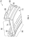
- the BOAS 70 includes a plurality of film cooling holes 86 for generating a film cooling air flow, indicated at 75 in FIG. 2 , along the gas path surface 72.
- the film cooling holes 86 are disposed on surfaces exposed to the exhaust gasses 68. It should be understood that the term "holes" is used by way of description and not intended to limit the shape to a round opening. Accordingly, the example holes 86 maybe round, oval, square or any other shape desired.
- BOAS 70 includes the gas path surface 72 that is exposed directly to the exhaust gasses 68.
- the BOAS 70 further includes a first side 74 and a second side 76 (See FIG. 6 ).
- the first and second sides 74, 76 abut adjacent BOASs disposed circumferentially about the turbine case 64.
- Each of the BOASs 70 includes a forward surface 78 and an aft surface 80.
- the forward surface 78 and aft surface 80 includes support features for holding each BOAS within the turbine case 64.
- the BOAS 70 includes a forward channel 90 and an aft tab 88 to conform to features within the turbine cases 64 to support the BOAS 70 circumferentially about the corresponding turbine blade 62.
- the first side 74 and second side 76 and a gas path surface 72 all include a plurality of film cooling holes 86.
- Each of the film cooling holes 86 provide a pathway for cooling air to generate the boundary layer of cooling air flow 75 to maintain the BOAS within defined temperature ranges.
- a specific location of the film cooling holes 86 is devised to provide cooling air flow coverage of features susceptible to the high temperature exhaust gasses.
- the cooling holes 86 are arranged to produce boundary layers of cooling flow along the gas path surface 72 along with the first side 74 and the second side 76. As appreciated, the first side and second side provide the cooling air holes 86 to inject cooling flow between adj acent blade outer air seals 70.
- the location of the cooling holes 86 are described in terms of Cartesian coordinates indicated by the axes 106 that includes X, Y and Z axes which correspond to the radial direction (Y), the circumferential direction (X), and the axial direction (Z) as is shown in FIG. 4 relative to a point of origin indicated at 84.
- the locations for the cooling holes 86 correspond to the location where the holes break through the surface of either the first side 74, the second 76 or the gas path surface 72.
- FIG. 7 is a perspective view of cooled turbine blade 62, which includes root 136, platform 138, and airfoil 140.
- Blade 62 may be, for example, a high pressure turbine blade.
- Root 136 of blade 62 may include a dovetail or fir tree geometry configured to be received in a slot in the rim of a rotor disc.
- Root 136 includes four cooling fluid supply channels 136a, 136b, 136c, and 136d.
- Platform 138 is integral with and radially outward of root 136.
- Supply channels 136a, 136b, 136c, and 136d extend through platform 138 into airfoil 140.
- Airfoil 140 of blade 62 extends radially from platform 138 to the tip of blade 62.
- Airfoil 140 includes concave pressure wall 142, convex suction wall 144, and cooling channels 150.
- Concave pressure wall 142 extends radially from the base to the tip of airfoil 140.
- Convex suction wall 144 is connected to concave pressure wall 142 at leading edge 146 and trailing edge 148 spaced axially from leading edge 146.
- Concave pressure wall 142 and convex suction wall 144 may include film cooling apertures, such as film cooling holes 150a, adapted to exhaust cooling fluid from cooling channels 150 onto the exterior surface of airfoil 140.
- Cooling channels 150 are formed between concave pressure wall 142 and convex suction wall 44 and configured to receive cooling fluid from supply channels 136a, 136b, 136c, and 136d. Cooling channels 150 include leading edge channel 152, trailing edge channel 154, serpentine cooling circuit 156, and dedicated up-pass channel 158. Leading edge channel 152 extends radially from the base toward the tip of airfoil 140 and is in flow communication with supply channel 136 a. Trailing edge channel 154 extends radially from the base toward the tip and is in flow communication with supply channel 136d and trailing edge apertures, such as holes and/or slots, adapted to exhaust cooling fluid to the exterior of airfoil 140.
- Serpentine circuit 156 includes first channel 156a, second channel 156b, and third channel 156c.
- First channel 156 a is forward of and adjacent to trailing edge channel 154 and extends radially from the base toward the tip of airfoil 140.
- First channel 156a is in flow communication with supply channel 136c.
- Second channel 156b is in flow communication with first channel 156a and extends radially adjacent the tip toward the base of airfoil 140.
- Third channel 156c is in flow communication with second channel 156b and extends radially from the base toward the tip of airfoil 140.
- Dedicated up-pass channel 158 extends radially from the base toward the tip of airfoil 140 between leading edge channel 152 and third channel 156c of serpentine circuit 156 and is in flow communication with supply channel 136b.
- blade 62 may be cooled using, for example, air bled from compressor section 24 shown in FIG. 1 .
- Compressor bleed air is fed to supply channels 136a, 136b, 136c, and 136d in root 136 of blade 62.
- Air flows radially outward through supply channel 36a into leading edge channel 152 inside airfoil 140.
- Air also flows radially outward through supply channel 136d into trailing edge channel 154 and may be exhausted to the exterior of airfoil 140 through trailing edge exhaust apertures, such as holes and/or slots.
- Blade 62 is convectively cooled, as the relatively cool air fed from the compressor flows through cooling channels 150 in airfoil 140. Additionally, blade 62 may include film cooling holes in concave pressure wall 142 and convex suction wall 144 adapted to exhaust cooling fluid from one or more of cooling channels 150 to the exterior surfaces of airfoil 140, thereby creating a thin layer of cooling fluid that insulates airfoil 140 from the hot working medium gas flowing over blade 62.
- cooling holes 150a manufactured via machining processes that include electro-discharge machining, laser drilling, laser ablation, or a combination thereof result in metal depletion from the region that immediately surrounds the cooling hole 150a.
- the airfoil in the form of a workpiece since it is not yet an airfoil
- a homogenization cycle in which the workpiece is heated to an elevated temperature for a time period that is sufficient to enable diffusion of the depleted metal elements into the depletion zone from regions surrounding the depletion zone.
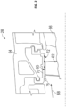
- FIGS. 8A depicts a section of an exemplary airfoil 1000 with a cooling hole 150a (about axis AA') of radius r 1 .
- FIG. 8A depicts the region of metal depletion 170 (of average radius r 2 ) that surrounds the cooling hole 150a as well as the region 180 that contains the base alloy (without any metal depletion) that surrounds the region of metal depletion 170.
- the distance from axis AA' (the center of the hole) is measured along arrow "r”.
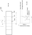
- FIG. 8B is a graph that measures metal concentration in the base alloy composition from the central axis AA' as "r" increases. The y-axis of the graph in FIG.
- the metal used in the airfoil has an initial composition depicted by the solid line titled "base alloy composition”.
- the region 180 (see FIG. 8A ) which lies outside the radius r 2 , has the base alloy composition. If no cooling hole was drilled in the alloy, the entire airfoil would have an initial composition that is represented by the solid line titled "base alloy composition”.
- the base alloy composition is depleted of some metals (such as, for example, aluminum and chromium) during the drilling of the hole. At least a portion of the initial composition is lost during the drilling of the hole to form a depleted region that surrounds the cooling hole.
- the depleted region contains a smaller amount of at least one element than that contained in the initial composition. In an embodiment, the depleted region contains a smaller amount of at least two elements than that contained in the initial composition.
- region 170 results in the formation of region 170 (see FIG. 8A ) within an average radius r 2 of axis AA' in the immediate vicinity of the cooling hole that suffers from alloy depletion.
- the workpiece undergoes a process of homogenization where metals in the region 180 that have not suffered depletion (non-depleted regions) diffuse into the region 170 that have suffered depletion.
- This new region of uniform concentration is represented by the dotted line titled "homogenized level".
- the concentration of metals in the originally depleted region 170 is the same as that in the region 180 (farther from the cooling hole 150a) that was previously not affected by the drilling of the hole.
- the new concentration of the depleted metal is lower across the entire workpiece than the original concentration of the metal in the base alloy.
- homogenization brings about a uniform distribution of metal concentration in the entire workpiece, it results in a slightly lower concentration of lost metals across the entire workpiece.
- the composition of the workpiece after homogenization is slightly different from that of the initial composition.
- the conduction of the homogenization step subsequent to the manufacturing of the cooling hole restores the alloy composition in depleted region via diffusion from the non-depleted base alloy. Homogenization results in a desirable reduction of the formation of oxides of nickel and cobalt on a surface of the cooling hole. In other words, the depleted surfaces of the cooling holes achieve a base chemistry oxidation resistance (upon undergoing homogenization) and do not prematurely undergo oxidization in a manner that adversely impacts the life of the airfoil.
- the homogenization may also be conducted retroactively on airfoils that have undergone service in the field.
- the process of homogenization may be conducted on a new workpiece (e.g., an airfoil) that is eventually machined into an airfoil as follows. First a metallic coat (also known as a bond coat) is applied to the workpiece (the airfoil). The cooling hole is then machined in the workpiece after which a top coat is applied to the workpiece. In an embodiment, the cooling hole may be machined after the bond coat and top coat are applied to the workpiece. The homogenization process is conducted after the cooling hole is machined and the top coat is applied to the workpiece. After the homogenization process, the workpiece is ready to be installed into a turbine as an airfoil.
- a metallic coat also known as a bond coat
- a first method comprises apply a metallic coat (hereinafter “bond coat”) to the workpiece that is to be formed into an airfoil.
- a bond coat is a type of coating that is applied to the surface of turbine airfoils to protect them from environmental degradation.
- the bond coat is the first layer of a thermal barrier coating (TBC), which is a ceramic coating with a very low thermal conductivity that reduces the alloy surface temperature by insulating it from the hot gas.
- TBC thermal barrier coating
- the cooling hole may be machined via electrical discharge machining or laser machining.
- the cooling hole may then be drilled via electrical discharge machining (EDM) (also known as spark machining, spark eroding, die sinking, wire burning or wire erosion), which is a metal fabrication process whereby a desired shape is obtained by using electrical discharges (sparks).
- EDM electrical discharge machining
- Material is removed from the workpiece by a series of rapidly recurring current discharges between two electrodes separated by a dielectric liquid and subject to an electric voltage.
- One of the electrodes is called the tool-electrode, or simply the tool or electrode, while the other is called the workpiece-electrode, or workpiece.
- the voltage between the two electrodes is increased, the intensity of the electric field in the volume between the electrodes becomes greater, causing dielectric break down of the liquid, and producing an electric arc. As a result, material is removed from the electrodes.
- laser machining is a non-contact process that uses heat directed from a laser beam to remove material from the workpiece.
- metal depletion occurs in the workpiece as detailed above.
- the non-depleted region contains an initial composition of a nickel-based superalloy or a cobalt-based superalloy.
- the depleted region contains a smaller amount of at least one element than that contained in the initial composition.
- the non-depleted region lies further away from a center of the cooling hole than the depleted region. The depleted region contacts a surface of the cooling hole, whereas a non-depleted region does not contact a surface of the cooling hole.
- a ceramic top coat is applied to the workpiece.
- the ceramic top coat is a type of coating that is applied to the surface of turbine blades to protect them from the high temperature and corrosive gases in the engine. Ceramic top coats have higher melting points and lower thermal conductivity than metal, which means they can reduce the heat transfer to the underlying metal substrate and extend the life of the turbine blades. Ceramic top coats are usually made of zirconia (ZrO 2 ) or alumina (Al 2 O 3 ) and are sprayed or plasma-deposited onto the turbine blades after they are coated with the bond coat. The bond coat provides adhesion and oxidation resistance for the ceramic top coat.
- Thermal barrier coatings are ceramic top coatings that are applied to the turbine blades to reduce the temperature of the metal surface by 100-300°C, which improves the thermodynamic efficiency and reduces pollutant emissions.
- TBCs are usually made of yttria-stabilized zirconia (YSZ), which has low thermal conductivity and good thermal expansion match with the bond coat.
- the thermal barrier coating may be applied to the workpiece prior to or after the machining of the cooling holes.
- the homogenization step includes heat treating the workpiece to a temperature of 1900 to 2350°F (about 1040 to 1290°C), preferably 2000 to 2300°F (about 1090 to 1260°C), and more preferably to 2100 to 2250°F, (about 1150 to 1230°C) for a time period of 0.5 hours to 50 hours, preferably for 1 to 10 hours.
- the heat treatment at the elevated temperature results in the redistribution of elements that are lost from the base alloy composition during the machining of the cooling holes.
- the heat treatment results in the depleted region having an almost similar composition to that of the non-depleted region.
- This readjustment results in the composition of the heat treated airfoil being slightly different from that of the initial composition of the airfoil prior to the machining of the cooling holes.
- aluminum and chromium in metal form are redistributed from the non-depleted portions of the airfoil to those portions of the airfoil that are depleted.
- Other metals present in the base alloy prior to machining of the holes such as nickel, tantalum, hafnium, silicon and yttrium may also diffuse from the depleted to non-depleted regions of the airfoil.
- the method disclosed herein is advantageous in that depleted regions and surfaces that surround cooling holes may achieve base chemistry oxidation resistance as a result of the homogenization process and do not undergo premature oxidation, which reduces part life.
- the heat treatment results in mitigation of an oxide formation rate in the cooling hole as compared with an oxide formation in the absence of the heat treatment.
Landscapes
- Engineering & Computer Science (AREA)
- Mechanical Engineering (AREA)
- Chemical & Material Sciences (AREA)
- General Engineering & Computer Science (AREA)
- Materials Engineering (AREA)
- Inorganic Chemistry (AREA)
- Chemical Kinetics & Catalysis (AREA)
- Metallurgy (AREA)
- Organic Chemistry (AREA)
- Fluid Mechanics (AREA)
- Physics & Mathematics (AREA)
- Ceramic Engineering (AREA)
- Turbine Rotor Nozzle Sealing (AREA)
Abstract
A method of reducing depletion of elements from an airfoil (140) includes disposing a bond coating on the airfoil (140), where the airfoil (140) comprises cooling channels (150). The airfoil (140) includes a material that has an initial composition. A cooling hole (150a) is machined in the airfoil (140) to contact the cooling channels (150) such that a fluid travelling in the cooling channel may be discharged via the cooling hole (150a). The machining of the cooling hole (150a) results in a formation of a depleted region (170) around the cooling hole (150a). The depleted region (170) is depleted of a portion of the initial composition of the airfoil (140). A top coat is disposed on the bond coat. The airfoil (140) is subjected to a heat treatment at a temperature effective to promote diffusion of elements from a non-depleted region (180) to the depleted region (170) around the cooling hole (150a).
Description
- This disclosure relates to restoring alloy depletion in an airfoil around a cooling hole. In particular, this disclosure relates to restoring metal elements from turbine vanes in the region surrounding cooling holes.
- Turbine airfoils are formed of blades and vanes. They are used in gas turbine engines and steam turbines to extract energy from the high-temperature, high-pressure gas produced by the combustor. Turbine airfoils are often manufactured from superalloys to withstand the harsh environment.
- Cooling holes are small openings in the turbine airfoils that allow cool air from the compressor to be discharged over the airfoil surface, forming a low-temperature film that protects the airfoils from the hot gas. Cooling holes are essential to avoid turbine failure and ensure the engines safe operation. Cooling holes are usually created by laser or electrical discharging machining methods.
- Alloy depletion in cooling holes of turbine airfoils is a phenomenon that occurs when the metal elements in the alloy are removed during airfoil manufacturing during the process of machining the cooling holes. The consequence of alloy depletion is lower oxidation and corrosion resistance on the surface. It is therefore desirable to rebalance alloy composition in the region proximate to the cooling hole in an airfoil.
- In an embodiment, a method of reducing depletion of elements from an airfoil includes disposing a bond coating on the airfoil, where the airfoil comprises a concave pressure wall, a convex suction wall and cooling channels. The concave pressure wall extends radially from a base to a tip of the airfoil and the convex suction wall contacts the concave pressure wall at a leading edge and at a trailing edge spaced axially from leading edge. The airfoil includes a material that has an initial composition. A cooling hole is machined in the airfoil to contact the cooling channels such that a fluid travelling in the cooling channel may be discharged via the cooling hole. The machining of the cooling hole results in a formation of a depleted region around the cooling hole. The depleted region is depleted of a portion of the initial composition of the airfoil. A top coat is disposed on the bond coat. The airfoil is subjected to a heat treatment at a temperature effective to promote diffusion of elements from a non-depleted region to the depleted region around the cooling hole. The non-depleted region is located further away from the cooling hole than the depleted region.
- In an embodiment of the previous embodiment, the depleted region contacts a surface of the cooling hole or cooling hole diffuser.
- In another embodiment of any of the previous embodiments, the initial composition comprises a nickel-based superalloy or a cobalt-based superalloy and where the depleted region contains a smaller amount of at least one element than that contained in the initial composition.
- In another embodiment of any of the previous embodiments, the initial composition comprises a nickel-based superalloy or a cobalt-based superalloy and where the depleted region contains a smaller amount of at least two elements than that contained in the initial composition.
- In yet another embodiment of any of the previous embodiments, the heat treatment is conducted at a temperature of 1900 to 2350°F (about 1040 to 1290°C) for a time period of 0.5 hours to 50 hours.
- In yet another embodiment of any of the previous embodiments, the heat treatment is conducted at a temperature of 2000 to 2300°F (about 1090 to 1260°C).
- In yet another embodiment of any of the previous embodiments, the heat treatment is conducted at a temperature of 2100 to 2250°F (about 1150 to 1230°C) for 1 to 10 hours.
- In yet another embodiment of any of the previous embodiments, the at least one element is either aluminum or chromium.
- In yet another embodiment of any of the previous embodiments, the at least two elements are aluminum and chromium.
- In yet another embodiment of any of the previous embodiments, a composition of the airfoil after heat treatment is different from that of the initial composition.
- In yet another embodiment of any of the previous embodiments, the machining of the cooling hole is conducted prior to the disposing of the top coat on the airfoil.
- In yet another embodiment of any of the previous embodiments, the machining of the cooling hole is conducted after the disposing of the top coat on the airfoil.
- In yet another embodiment of any of the previous embodiments, the depleted region has a smaller amount of at least one element than that contained in the non-depleted region.
- In yet another embodiment of any of the previous embodiments, the depleted region has a smaller amount of at least two elements than that contained in the non-depleted region.
- In yet another embodiment of any of the previous embodiments, the heat treatment results in mitigation of an oxide formation rate in the cooling hole as compared with an oxide formation in the absence of the heat treatment.
- In yet another embodiment of any of the previous embodiments, the top coat is a thermal barrier coating.
- In yet another embodiment of any of the previous embodiments, the thermal barrier coating comprises yttria stabilized zirconia.
-
-
FIG. 1 is a schematic, partial cross-sectional view of a turbomachine in accordance with this disclosure; -
FIG. 2 is a schematic view of a portion of a turbine section of a gas turbine engine; -
FIG. 3 is a perspective view of an example blade outer air seal; -
FIG. 4 is a another perspective view of the example blade outer air seal; -
FIG. 5 is a first side view of an example blade outer air seal; -
FIG. 6 is a second side view of an example blade outer air seal; -
FIG. 7 is a depiction of an exemplary airfoil; and -
FIG. 8A is a depiction of a portion of an airfoil in the region around a cooling hole; and -
FIG. 8B is a graph that depicts the concentration of elements around a cooling hole in the initial composition and in the composition after homogenization. - Disclosed herein is method of rebalancing metal alloy composition in the region around cooling holes in a turbine airfoil (hereinafter "airfoil"). Turbine airfoils encompass turbine vanes or blade outer air seals/shrouds (BOAS). As noted above, alloys that are used to manufacture airfoils are often depleted (of some metal elements) during the formation of cooling holes in the airfoil. The depletion of these elements may result in shortening the life of the airfoil and hence of the turbine. The depletion of these elements is compensated for by conducting a homogenization step on the airfoil at an elevated temperature for a period of time sufficient to replenish the depleted region with the depleted elements that are drawn from non-depleted regions of the airfoil. The treatment at the elevated temperature permits diffusion of the elements from an non-depleted region to a region that has lost these elements during the process of machining a cooling hole.
- Airfoils may comprise a nickel-based superalloy that comprises chromium and aluminum amongst other elements. These alloys have high strength, corrosion resistance, and creep resistance at high temperatures. Nickel-based superalloys used in airfoils include elements selected from nickel, chromium, aluminum, tantalum, hafnium, silicon, and yttrium. In other embodiments, in addition to the previously mentioned elements, the nickel-based superalloy may include one or more elements selected from carbon, boron, and zirconium. In yet another embodiment, the nickel-based superalloy further may include tungsten. In still another embodiment, the nickel-based superalloy may include incidental impurities (e.g., trace amounts of additional elements that are not intentionally included in the composition) but does not include other elements other than those listed previously. Examples of nickel-based superalloys used in the airfoil are but not limited to IN792, C101, MarM247, Rene80, Rene125, ReneN5, SC180, CMSX 4, and PWA1484.
- Cobalt-based superalloys may also be used in the turbine airfoils and may be subjected to a homogenization process detailed below.
- In an embodiment, the nickel-based superalloy contains more than 50 percent of nickel by weight and permits solidification of the whole airfoil as a single crystal. The use of single-crystal superalloys provides additional strength to the metal, making it able to withstand the high temperatures and stresses in the turbine. The nickel-based superalloy may be directionally solidified alloys or equiaxed materials, L turbine parts, vanes and BOAS.
- Processes used to machine cooling holes include electro-discharge machining, laser drilling, laser ablation, or a combination thereof. Transient melting caused during these machining processes causes certain metals such as aluminum and chromium present in the alloy to evaporate when melting occurs. This results in a depletion of these metals from the alloy at the surface of the cooling hole especially when compared with the initial metal content in the alloy (prior to the machining of the hole) or when compared with the metal content in the alloy at a distance away from the cooling hole. It is desirable to have aluminum and chromium in the requisite quantities in the alloy because they are used to provide oxidation resistance in the single crystal alloys used in airfoils.
-
FIG. 1 schematically illustrates agas turbine engine 20. Thegas turbine engine 20 is disclosed herein as a two-spool turbofan that generally incorporates afan section 22, acompressor section 24, acombustor section 26 and aturbine section 28. Alternative engines might include an augmentor section (not shown) among other systems or features. Thefan section 22 drives air along a bypass flow path B in a bypass duct, while thecompressor section 24 drives air along a core flow path C for compression and communication into thecombustor section 26 then expansion through theturbine section 28. Although depicted as a two-spool turbofan gas turbine engine in the disclosed non-limiting embodiment, it should be understood that the concepts described herein are not limited to use with two-spool turbofans as the teachings may be applied to other types of turbine engines including three-spool architectures. - The
exemplary engine 20 generally includes alow speed spool 30 and ahigh speed spool 32 mounted for rotation about an engine central longitudinal axis A relative to an enginestatic structure 36 viaseveral bearing systems 38. It should be understood that various bearingsystems 38 at various locations may alternatively or additionally be provided, and the location of bearingsystems 38 may be varied as appropriate to the application. - The
low speed spool 30 generally includes aninner shaft 40 that interconnects afan 42, alow pressure compressor 44 and alow pressure turbine 46. Theinner shaft 40 is connected to thefan 42 through a speed change mechanism, which in exemplarygas turbine engine 20 is illustrated as a gearedarchitecture 48 to drive thefan 42 at a lower speed than thelow speed spool 30. Thehigh speed spool 32 includes anouter shaft 50 that interconnects ahigh pressure compressor 52 andhigh pressure turbine 54. Acombustor 56 is arranged inexemplary gas turbine 20 between thehigh pressure compressor 52 and thehigh pressure turbine 54. An enginestatic structure 36 is arranged generally between thehigh pressure turbine 54 and thelow pressure turbine 46. The enginestatic structure 36 furthersupports bearing systems 38 in theturbine section 28. A mid-turbine frame 58 of the enginestatic structure 36 is arranged generally between thehigh pressure turbine 54 and thelow pressure turbine 46. The mid-turbine frame 58 furthersupports bearing systems 38 in theturbine section 28. Theinner shaft 40 and theouter shaft 50 are concentric and rotate via bearingsystems 38 about the engine central longitudinal axis A which is collinear with their longitudinal axes. Theinner shaft 40 and theouter shaft 50 are concentric and rotate via bearingsystems 38 about the engine central longitudinal axis A which is collinear with their longitudinal axes. - The core airflow is compressed by the
low pressure compressor 44 then thehigh pressure compressor 52, mixed and burned with fuel in thecombustor 56, then expanded over thehigh pressure turbine 54 andlow pressure turbine 46. Theturbines low speed spool 30 andhigh speed spool 32 in response to the expansion. It will be appreciated that each of the positions of thefan section 22,compressor section 24,combustor section 26,turbine section 28, and fandrive gear system 48 may be varied. For example,gear system 48 may be located aft ofcombustor section 26 or even aft ofturbine section 28, andfan section 22 may be positioned forward or aft of the location ofgear system 48. - The
engine 20 in one example is a high-bypass geared aircraft engine. In a further example, theengine 20 bypass ratio is greater than about six (6), with an example embodiment being greater than about ten (10), the gearedarchitecture 48 is an epicyclic gear train, such as a planetary gear system or other gear system, with a gear reduction ratio of greater than about 2.3 and thelow pressure turbine 46 has a pressure ratio that is greater than about five. In one disclosed embodiment, theengine 20 bypass ratio is greater than about ten (10:1), the fan diameter is significantly larger than that of thelow pressure compressor 44, and thelow pressure turbine 46 has a pressure ratio that is greater than about five (5:1). -
Low pressure turbine 46 pressure ratio is pressure measured prior to inlet oflow pressure turbine 46 as related to the pressure at the outlet of thelow pressure turbine 46 prior to an exhaust nozzle. The gearedarchitecture 48 may be an epicycle gear train, such as a planetary gear system or other gear system, with a gear reduction ratio of greater than about 2.3:1. It should be understood, however, that the above parameters are only exemplary of one embodiment of a geared architecture engine and that the present disclosure is applicable to other gas turbine engines including direct drive turbofans. - The example gas turbine engine includes the
fan 42 that comprises in one non-limiting embodiment less than about twenty-six (26) fan blades. In another non-limiting embodiment, thefan section 22 includes less than about twenty (20) fan blades. Moreover, in one disclosed embodiment thelow pressure turbine 46 includes no more than about six (6) turbine rotors schematically indicated at 34. In another non-limiting example embodiment thelow pressure turbine 46 includes about three (3) turbine rotors. A ratio between the number offan blades 42 and the number of low pressure turbine rotors is between about 3.3 and about 8.6. The examplelow pressure turbine 46 provides the driving power to rotate thefan section 22 and therefore the relationship between the number of turbine rotors 34 in thelow pressure turbine 46 and the number ofblades 42 in thefan section 22 disclose an examplegas turbine engine 20 with increased power transfer efficiency. - Referring to
FIGS. 1 and2 , theexample turbine section 28 includes at least one rotor having aturbine blade 62. Theturbine blade 62 includes atip 65 disposed adjacent to a blade outer air seal 70 (BOAS). Astationary vane 66 is mounted and supported within thecase 64 on at least one side of theturbine blade 62 for directing gas flow into the next turbine stage. Thestationary vane 66 also contains cooling holes (not shown). TheBOAS 70 is disposed adjacent to thetip 65 to provide a desired clearance between thetip 65 and a gas path surface 72 of theBOAS 70. The clearance provides for increase efficiency with regard to the extraction of energy from the high energy gas flow indicated byarrow 68. - The
turbine blade 62 andvane 66 along with the blade outer air seal are exposed to the high-energyexhaust gas flow 68. The high energyexhaust gas flow 68 is at an elevated temperature and thereby structures such as theblade 62,vane 66 and theBOAS 70 are fabricated from materials capable of withstanding the extremes in temperature. Moreover, each of these structures may include provisions for generating a coolingfilm air flow 75 over the surfaces. The cooling film air flow generates a boundary layer that aids in survivability for the various structures within the path of theexhaust gasses 68. - In the disclosed example, a plurality of
BOAS 70 are supported within thecase 64 and abut each other to form a circumferential boundary radially outward of thetip 65. Accordingly, at least one stage of theturbine section 28 includes a plurality ofBOAS 70 that define a radial clearance between thetip 65 and the gas path surface 72. Additional stages in theturbine section 28 will include additional BOAS to define the radial clearance with turbine blades of each stage. - Referring to
FIG. 3 with continued reference toFIG. 2 , theBOAS 70 includes a plurality of film cooling holes 86 for generating a film cooling air flow, indicated at 75 inFIG. 2 , along the gas path surface 72. The film cooling holes 86 are disposed on surfaces exposed to theexhaust gasses 68. It should be understood that the term "holes" is used by way of description and not intended to limit the shape to a round opening. Accordingly, the example holes 86 maybe round, oval, square or any other shape desired. -
BOAS 70 includes the gas path surface 72 that is exposed directly to theexhaust gasses 68. TheBOAS 70 further includes afirst side 74 and a second side 76 (SeeFIG. 6 ). The first andsecond sides turbine case 64. Each of theBOASs 70 includes aforward surface 78 and anaft surface 80. Theforward surface 78 andaft surface 80 includes support features for holding each BOAS within theturbine case 64. In this example, theBOAS 70 includes aforward channel 90 and anaft tab 88 to conform to features within theturbine cases 64 to support theBOAS 70 circumferentially about the correspondingturbine blade 62. - The
first side 74 andsecond side 76 and a gas path surface 72 all include a plurality of film cooling holes 86. Each of the film cooling holes 86 provide a pathway for cooling air to generate the boundary layer of coolingair flow 75 to maintain the BOAS within defined temperature ranges. A specific location of the film cooling holes 86 is devised to provide cooling air flow coverage of features susceptible to the high temperature exhaust gasses. The cooling holes 86 are arranged to produce boundary layers of cooling flow along the gas path surface 72 along with thefirst side 74 and thesecond side 76. As appreciated, the first side and second side provide the cooling air holes 86 to inject cooling flow between adj acent blade outer air seals 70. - The location of the cooling holes 86 are described in terms of Cartesian coordinates indicated by the
axes 106 that includes X, Y and Z axes which correspond to the radial direction (Y), the circumferential direction (X), and the axial direction (Z) as is shown inFIG. 4 relative to a point of origin indicated at 84. The locations for the cooling holes 86 correspond to the location where the holes break through the surface of either thefirst side 74, the second 76 or the gas path surface 72. -
FIG. 7 is a perspective view of cooledturbine blade 62, which includesroot 136,platform 138, andairfoil 140.Blade 62 may be, for example, a high pressure turbine blade.Root 136 ofblade 62 may include a dovetail or fir tree geometry configured to be received in a slot in the rim of a rotor disc.Root 136 includes four coolingfluid supply channels Platform 138 is integral with and radially outward ofroot 136.Supply channels platform 138 intoairfoil 140.Airfoil 140 ofblade 62 extends radially fromplatform 138 to the tip ofblade 62.Airfoil 140 includesconcave pressure wall 142,convex suction wall 144, and coolingchannels 150.Concave pressure wall 142 extends radially from the base to the tip ofairfoil 140.Convex suction wall 144 is connected toconcave pressure wall 142 at leadingedge 146 and trailingedge 148 spaced axially from leadingedge 146.Concave pressure wall 142 andconvex suction wall 144 may include film cooling apertures, such asfilm cooling holes 150a, adapted to exhaust cooling fluid from coolingchannels 150 onto the exterior surface ofairfoil 140. - Cooling
channels 150 are formed betweenconcave pressure wall 142 andconvex suction wall 44 and configured to receive cooling fluid fromsupply channels channels 150 include leadingedge channel 152, trailingedge channel 154,serpentine cooling circuit 156, and dedicated up-pass channel 158. Leadingedge channel 152 extends radially from the base toward the tip ofairfoil 140 and is in flow communication withsupply channel 136 a. Trailingedge channel 154 extends radially from the base toward the tip and is in flow communication withsupply channel 136d and trailing edge apertures, such as holes and/or slots, adapted to exhaust cooling fluid to the exterior ofairfoil 140.Serpentine circuit 156 includesfirst channel 156a,second channel 156b, andthird channel 156c.First channel 156 a is forward of and adjacent to trailingedge channel 154 and extends radially from the base toward the tip ofairfoil 140.First channel 156a is in flow communication withsupply channel 136c.Second channel 156b is in flow communication withfirst channel 156a and extends radially adjacent the tip toward the base ofairfoil 140.Third channel 156c is in flow communication withsecond channel 156b and extends radially from the base toward the tip ofairfoil 140. Dedicated up-pass channel 158 extends radially from the base toward the tip ofairfoil 140 betweenleading edge channel 152 andthird channel 156c ofserpentine circuit 156 and is in flow communication withsupply channel 136b. - During engine operation,
blade 62 may be cooled using, for example, air bled fromcompressor section 24 shown inFIG. 1 . Compressor bleed air is fed to supplychannels root 136 ofblade 62. Air flows radially outward through supply channel 36a into leadingedge channel 152 insideairfoil 140. Air also flows radially outward throughsupply channel 136d into trailingedge channel 154 and may be exhausted to the exterior ofairfoil 140 through trailing edge exhaust apertures, such as holes and/or slots. Air flows radially outward throughsupply channel 136c intofirst channel 156a ofserpentine circuit 156. The air flow inserpentine circuit 156 continues fromfirst channel 156a intosecond channel 156b andthird channel 156c. Finally, the remaining portion of compressor bleed air flows radially outward throughsupply channel 136b into dedicated up-pass channel 158.Blade 62 is convectively cooled, as the relatively cool air fed from the compressor flows through coolingchannels 150 inairfoil 140. Additionally,blade 62 may include film cooling holes inconcave pressure wall 142 andconvex suction wall 144 adapted to exhaust cooling fluid from one or more of coolingchannels 150 to the exterior surfaces ofairfoil 140, thereby creating a thin layer of cooling fluid that insulatesairfoil 140 from the hot working medium gas flowing overblade 62. - As noted above,
cooling holes 150a manufactured via machining processes that include electro-discharge machining, laser drilling, laser ablation, or a combination thereof result in metal depletion from the region that immediately surrounds thecooling hole 150a. In order to restore the metal content in the region immediately surrounding the cooling hole, the airfoil (in the form of a workpiece since it is not yet an airfoil) is subjected to a homogenization cycle in which the workpiece is heated to an elevated temperature for a time period that is sufficient to enable diffusion of the depleted metal elements into the depletion zone from regions surrounding the depletion zone. -
FIGS. 8A depicts a section of anexemplary airfoil 1000 with acooling hole 150a (about axis AA') of radius r1.FIG. 8A depicts the region of metal depletion 170 (of average radius r2) that surrounds thecooling hole 150a as well as theregion 180 that contains the base alloy (without any metal depletion) that surrounds the region ofmetal depletion 170. The distance from axis AA' (the center of the hole) is measured along arrow "r".FIG. 8B is a graph that measures metal concentration in the base alloy composition from the central axis AA' as "r" increases. The y-axis of the graph inFIG. 8B is aligned with the central axis AA' of theFIG. 8A . The metal used in the airfoil has an initial composition depicted by the solid line titled "base alloy composition". The region 180 (seeFIG. 8A ) which lies outside the radius r2, has the base alloy composition. If no cooling hole was drilled in the alloy, the entire airfoil would have an initial composition that is represented by the solid line titled "base alloy composition". - As may be seen from the
FIG. 8B , the base alloy composition is depleted of some metals (such as, for example, aluminum and chromium) during the drilling of the hole. At least a portion of the initial composition is lost during the drilling of the hole to form a depleted region that surrounds the cooling hole. In an embodiment, the depleted region contains a smaller amount of at least one element than that contained in the initial composition. In an embodiment, the depleted region contains a smaller amount of at least two elements than that contained in the initial composition. - This results in the formation of region 170 (see
FIG. 8A ) within an average radius r2 of axis AA' in the immediate vicinity of the cooling hole that suffers from alloy depletion. When the workpiece is subjected to an elevated temperature, the workpiece undergoes a process of homogenization where metals in theregion 180 that have not suffered depletion (non-depleted regions) diffuse into theregion 170 that have suffered depletion. This results in a uniform concentration of the depleted metals in the entire region of the workpiece. This new region of uniform concentration is represented by the dotted line titled "homogenized level". It may be seen that the concentration of metals in the originally depletedregion 170 is the same as that in the region 180 (farther from thecooling hole 150a) that was previously not affected by the drilling of the hole. The new concentration of the depleted metal is lower across the entire workpiece than the original concentration of the metal in the base alloy. Thus, while homogenization brings about a uniform distribution of metal concentration in the entire workpiece, it results in a slightly lower concentration of lost metals across the entire workpiece. The composition of the workpiece after homogenization is slightly different from that of the initial composition. - The conduction of the homogenization step subsequent to the manufacturing of the cooling hole restores the alloy composition in depleted region via diffusion from the non-depleted base alloy. Homogenization results in a desirable reduction of the formation of oxides of nickel and cobalt on a surface of the cooling hole. In other words, the depleted surfaces of the cooling holes achieve a base chemistry oxidation resistance (upon undergoing homogenization) and do not prematurely undergo oxidization in a manner that adversely impacts the life of the airfoil. The homogenization may also be conducted retroactively on airfoils that have undergone service in the field.
- The process of homogenization may be conducted on a new workpiece (e.g., an airfoil) that is eventually machined into an airfoil as follows. First a metallic coat (also known as a bond coat) is applied to the workpiece (the airfoil). The cooling hole is then machined in the workpiece after which a top coat is applied to the workpiece. In an embodiment, the cooling hole may be machined after the bond coat and top coat are applied to the workpiece. The homogenization process is conducted after the cooling hole is machined and the top coat is applied to the workpiece. After the homogenization process, the workpiece is ready to be installed into a turbine as an airfoil.
- A first method comprises apply a metallic coat (hereinafter "bond coat") to the workpiece that is to be formed into an airfoil. A bond coat is a type of coating that is applied to the surface of turbine airfoils to protect them from environmental degradation. The bond coat is the first layer of a thermal barrier coating (TBC), which is a ceramic coating with a very low thermal conductivity that reduces the alloy surface temperature by insulating it from the hot gas. The bond coat is usually made of diffusion aluminide or MCrAlY (M = Ni, Co, or NiCo).
- The cooling hole may be machined via electrical discharge machining or laser machining. In an embodiment, the cooling hole may then be drilled via electrical discharge machining (EDM) (also known as spark machining, spark eroding, die sinking, wire burning or wire erosion), which is a metal fabrication process whereby a desired shape is obtained by using electrical discharges (sparks). Material is removed from the workpiece by a series of rapidly recurring current discharges between two electrodes separated by a dielectric liquid and subject to an electric voltage. One of the electrodes is called the tool-electrode, or simply the tool or electrode, while the other is called the workpiece-electrode, or workpiece. When the voltage between the two electrodes is increased, the intensity of the electric field in the volume between the electrodes becomes greater, causing dielectric break down of the liquid, and producing an electric arc. As a result, material is removed from the electrodes.
- In another embodiment, laser machining is a non-contact process that uses heat directed from a laser beam to remove material from the workpiece. During the machining process to form the cooling holes, metal depletion occurs in the workpiece as detailed above. In an embodiment, the non-depleted region contains an initial composition of a nickel-based superalloy or a cobalt-based superalloy. The depleted region contains a smaller amount of at least one element than that contained in the initial composition. The non-depleted region lies further away from a center of the cooling hole than the depleted region. The depleted region contacts a surface of the cooling hole, whereas a non-depleted region does not contact a surface of the cooling hole.
- Following the formation of the cooling holes, a ceramic top coat is applied to the workpiece. The ceramic top coat is a type of coating that is applied to the surface of turbine blades to protect them from the high temperature and corrosive gases in the engine. Ceramic top coats have higher melting points and lower thermal conductivity than metal, which means they can reduce the heat transfer to the underlying metal substrate and extend the life of the turbine blades. Ceramic top coats are usually made of zirconia (ZrO2) or alumina (Al2O3) and are sprayed or plasma-deposited onto the turbine blades after they are coated with the bond coat. The bond coat provides adhesion and oxidation resistance for the ceramic top coat.
- Thermal barrier coatings (TBCs) are ceramic top coatings that are applied to the turbine blades to reduce the temperature of the metal surface by 100-300°C, which improves the thermodynamic efficiency and reduces pollutant emissions. TBCs are usually made of yttria-stabilized zirconia (YSZ), which has low thermal conductivity and good thermal expansion match with the bond coat.
- As noted above, the thermal barrier coating may be applied to the workpiece prior to or after the machining of the cooling holes.
- The homogenization step includes heat treating the workpiece to a temperature of 1900 to 2350°F (about 1040 to 1290°C), preferably 2000 to 2300°F (about 1090 to 1260°C), and more preferably to 2100 to 2250°F, (about 1150 to 1230°C) for a time period of 0.5 hours to 50 hours, preferably for 1 to 10 hours.
- The heat treatment at the elevated temperature results in the redistribution of elements that are lost from the base alloy composition during the machining of the cooling holes. The heat treatment results in the depleted region having an almost similar composition to that of the non-depleted region. This readjustment results in the composition of the heat treated airfoil being slightly different from that of the initial composition of the airfoil prior to the machining of the cooling holes. In an embodiment, aluminum and chromium in metal form are redistributed from the non-depleted portions of the airfoil to those portions of the airfoil that are depleted. Other metals present in the base alloy prior to machining of the holes such as nickel, tantalum, hafnium, silicon and yttrium may also diffuse from the depleted to non-depleted regions of the airfoil.
- The method disclosed herein is advantageous in that depleted regions and surfaces that surround cooling holes may achieve base chemistry oxidation resistance as a result of the homogenization process and do not undergo premature oxidation, which reduces part life. In an embodiment, the heat treatment results in mitigation of an oxide formation rate in the cooling hole as compared with an oxide formation in the absence of the heat treatment.
- While the invention has been described with reference to some embodiments, it will be understood by those skilled in the art that various changes may be made and equivalents may be substituted for elements thereof without departing from the scope of the invention. In addition, many modifications may be made to adapt a particular situation or material to the teachings of the invention without departing from essential scope thereof. Therefore, it is intended that the invention is not limited to the particular embodiments disclosed as the best mode contemplated for carrying out this invention, but that the invention will include all embodiments falling within the scope of the appended claims.
Claims (15)
- A method of reducing depletion of elements from an airfoil (140; 1000) comprising:disposing a bond coating on the airfoil (140; 1000), where the airfoil (140; 1000) comprises a concave pressure wall (142), a convex suction wall (144) and cooling channels (150); where the concave pressure wall (142) extends radially from a base to a tip of the airfoil (140; 1000) and where the convex suction wall (144) contacts the concave pressure wall (142) at a leading edge (146) and at a trailing edge (148) spaced axially from leading edge (146); where the airfoil (140; 1000) comprises a material that has an initial composition;machining a cooling hole (150a) in the airfoil (140; 1000) to contact the cooling channels (150) such that a fluid travelling in the cooling channel may be discharged via the cooling hole (150a); where the machining of the cooling hole (150a) results in a formation of a depleted region (170) around the cooling hole (150a); where the depleted region (170) is depleted of a portion of the initial composition of the airfoil (140; 1000);disposing a top coat on the bond coat; andsubjecting the airfoil (140; 1000) to a heat treatment at a temperature effective to promote diffusion of elements from a non-depleted region (180) to the depleted region (170) around the cooling hole (150a); where the non-depleted region (180) is located further away from the cooling hole (150a) than the depleted region (170).
- The method of claim 1, where the depleted region (170) contacts a surface of the cooling hole (150a) or cooling hole diffuser.
- The method of claim 2, where the initial composition comprises a nickel-based superalloy or a cobalt-based superalloy and where the depleted region (170) contains a smaller amount of at least one element than that contained in the initial composition.
- The method of claim 3, where the at least one element is either aluminum or chromium.
- The method of claim 2, where the initial composition comprises a nickel-based superalloy or a cobalt-based superalloy and where the depleted region (170) contains a smaller amount of at least two elements than that contained in the initial composition.
- The method of claim 5, where the at least two elements are aluminum and chromium.
- The method of any preceding claim, where the heat treatment is conducted at a temperature of 1900 to 2350°F (about 1040 to 1290°C), optionally 2000 to 2300°F (about 1090 to 1260°C) or 2100 to 2250°F (about 1150 to 1230°C), for a time period of 0.5 hours to 50 hours, optionally 1 to 10 hours.
- The method of any preceding claim, where a composition of the airfoil (140; 1000) after heat treatment is different from that of the initial composition.
- The method of any preceding claim, where the machining of the cooling hole (150a) is conducted prior to the disposing of the top coat on the airfoil (140; 1000).
- The method of any of claims 1 to 8, where the machining of the cooling hole (150a) is conducted after the disposing of the top coat on the airfoil (140; 1000).
- The method of any preceding claim, where the depleted region (170) has a smaller amount of at least one element than that contained in the non-depleted region (180).
- The method of any preceding claim, where the depleted region (170) has a smaller amount of at least two elements than that contained in the non-depleted region (180).
- The method of any preceding claim, where the heat treatment results in mitigation of an oxide formation rate in the cooling hole (150a) as compared with an oxide formation in the absence of the heat treatment.
- The method of any preceding claim, where the top coat is a thermal barrier coating.
- The method of claim 14, where the thermal barrier coating comprises yttria-stabilized zirconia.
Applications Claiming Priority (1)
| Application Number | Priority Date | Filing Date | Title |
|---|---|---|---|
| US18/468,404 US12203384B1 (en) | 2023-09-15 | 2023-09-15 | Method of restoring alloy depletion in an airfoil around cooling holes |
Publications (1)
| Publication Number | Publication Date |
|---|---|
| EP4524368A1 true EP4524368A1 (en) | 2025-03-19 |
Family
ID=92801341
Family Applications (1)
| Application Number | Title | Priority Date | Filing Date |
|---|---|---|---|
| EP24200601.3A Pending EP4524368A1 (en) | 2023-09-15 | 2024-09-16 | Method of restoring alloy depletion around cooling holes in an airfoil |
Country Status (2)
| Country | Link |
|---|---|
| US (2) | US12203384B1 (en) |
| EP (1) | EP4524368A1 (en) |
Citations (5)
| Publication number | Priority date | Publication date | Assignee | Title |
|---|---|---|---|---|
| US5967755A (en) * | 1995-07-25 | 1999-10-19 | Siemens Aktiengesellschaft | Product with a metallic basic body and method for manufacturing a product |
| US20050058547A1 (en) * | 2003-06-05 | 2005-03-17 | General Electric Company, Schenectady, Ny | Bond coat process for thermal barrier coating |
| DE69934766T2 (en) * | 1998-12-22 | 2007-10-11 | General Electric Co. | Renewal of a heat-retardant coating system |
| US20120084981A1 (en) * | 2010-10-07 | 2012-04-12 | Hideyuki Arikawa | Method of working cooling hole of turbine blade |
| EP4332269A1 (en) * | 2022-08-05 | 2024-03-06 | RTX Corporation | Internal aluminide coating for vanes and blades and method of manufacture |
Family Cites Families (7)
| Publication number | Priority date | Publication date | Assignee | Title |
|---|---|---|---|---|
| US4953777A (en) | 1986-10-08 | 1990-09-04 | Chromalloy Gas Turbine Corporation | Method for repairing by solid state diffusion metal parts having damaged holes |
| US6042879A (en) * | 1997-07-02 | 2000-03-28 | United Technologies Corporation | Method for preparing an apertured article to be recoated |
| EP1298230A1 (en) * | 2001-10-01 | 2003-04-02 | Siemens Aktiengesellschaft | Process for removing corrosion products from metallic parts |
| CA2461732C (en) | 2001-10-18 | 2010-05-25 | Kadant Black Clawson Inc. | Extraction bedplate with laser or water jet cut apertures |
| US20120156054A1 (en) * | 2010-12-15 | 2012-06-21 | General Electric Company | Turbine component with near-surface cooling passage and process therefor |
| US20180297156A1 (en) * | 2017-04-13 | 2018-10-18 | General Electric Company | Repaired Airfoil with Improved Coating System and Methods of Forming the Same |
| US20240229244A9 (en) * | 2022-10-24 | 2024-07-11 | General Electric Company | Coating system for components in need of repair |
-
2023
- 2023-09-15 US US18/468,404 patent/US12203384B1/en active Active
-
2024
- 2024-09-16 EP EP24200601.3A patent/EP4524368A1/en active Pending
-
2025
- 2025-01-17 US US19/030,953 patent/US20250163808A1/en active Pending
Patent Citations (5)
| Publication number | Priority date | Publication date | Assignee | Title |
|---|---|---|---|---|
| US5967755A (en) * | 1995-07-25 | 1999-10-19 | Siemens Aktiengesellschaft | Product with a metallic basic body and method for manufacturing a product |
| DE69934766T2 (en) * | 1998-12-22 | 2007-10-11 | General Electric Co. | Renewal of a heat-retardant coating system |
| US20050058547A1 (en) * | 2003-06-05 | 2005-03-17 | General Electric Company, Schenectady, Ny | Bond coat process for thermal barrier coating |
| US20120084981A1 (en) * | 2010-10-07 | 2012-04-12 | Hideyuki Arikawa | Method of working cooling hole of turbine blade |
| EP4332269A1 (en) * | 2022-08-05 | 2024-03-06 | RTX Corporation | Internal aluminide coating for vanes and blades and method of manufacture |
Also Published As
| Publication number | Publication date |
|---|---|
| US12203384B1 (en) | 2025-01-21 |
| US20250163808A1 (en) | 2025-05-22 |
Similar Documents
| Publication | Publication Date | Title |
|---|---|---|
| EP1245787B1 (en) | Cooling system for a coated turbine blade tip | |
| US8319146B2 (en) | Method and apparatus for laser cutting a trench | |
| EP2578720B1 (en) | Repair methods for cooled components | |
| US8739404B2 (en) | Turbine components with cooling features and methods of manufacturing the same | |
| EP3106619B1 (en) | Hot gas path component having nea r wall cooling features | |
| EP2113636B1 (en) | Coated turbine-stage nozzle segments | |
| US8545185B2 (en) | Turbine engine components with environmental protection for interior passages | |
| JP2010126812A (en) | Repair method for tbc coated turbine components | |
| US20160199930A1 (en) | Combined braze and coating method for fabrication and repair of mechanical components | |
| US20170252870A1 (en) | Brazing tape or preform for microchannels in a thermal barrier coating | |
| US20180087394A1 (en) | Turbine systems with sealing components | |
| US8292587B2 (en) | Turbine blade assemblies and methods of manufacturing the same | |
| CN104651772B (en) | Method for changing orifice and system for changing flow through member | |
| EP4524368A1 (en) | Method of restoring alloy depletion around cooling holes in an airfoil | |
| US20260117658A1 (en) | Method of restoring alloy depletion in an airfoil around cooling holes | |
| JP2020522641A (en) | Turbine blade with squealer tip and dense oxide dispersion strengthened layer | |
| EP4134193A1 (en) | Forming cooling aperture(s) using electrical discharge machining | |
| US8123464B2 (en) | Coating optimization process using a coupon and component comprising a coupon | |
| EP4729743A1 (en) | Turbine blade outermost abrasive layer using graded ceramics | |
| US20240293892A1 (en) | Forming cooling aperture(s) in a turbine engine component | |
| JP2026075052A (en) | Turbine blade outermost polishing layer using gradient ceramic | |
| US20090208344A1 (en) | Process For The Electrolytic Treatment Of A Component, And A Component With Through-Hole | |
| US20230052285A1 (en) | Forming cooling aperture(s) in a turbine engine component | |
| Kool et al. | Operational Experience With Internal Coatings in Aero-and Industrial Gas Turbine Airfoils | |
| WO2018038738A1 (en) | Multi-layer protective coating enabling nickel diffusion |
Legal Events
| Date | Code | Title | Description |
|---|---|---|---|
| PUAI | Public reference made under article 153(3) epc to a published international application that has entered the european phase |
Free format text: ORIGINAL CODE: 0009012 |
|
| STAA | Information on the status of an ep patent application or granted ep patent |
Free format text: STATUS: THE APPLICATION HAS BEEN PUBLISHED |
|
| AK | Designated contracting states |
Kind code of ref document: A1 Designated state(s): AL AT BE BG CH CY CZ DE DK EE ES FI FR GB GR HR HU IE IS IT LI LT LU LV MC ME MK MT NL NO PL PT RO RS SE SI SK SM TR |
|
| STAA | Information on the status of an ep patent application or granted ep patent |
Free format text: STATUS: REQUEST FOR EXAMINATION WAS MADE |
|
| 17P | Request for examination filed |
Effective date: 20250919 |