EP4524359A1 - Control system, rock drilling unit, and method - Google Patents
Control system, rock drilling unit, and method Download PDFInfo
- Publication number
- EP4524359A1 EP4524359A1 EP23197347.0A EP23197347A EP4524359A1 EP 4524359 A1 EP4524359 A1 EP 4524359A1 EP 23197347 A EP23197347 A EP 23197347A EP 4524359 A1 EP4524359 A1 EP 4524359A1
- Authority
- EP
- European Patent Office
- Prior art keywords
- feed
- rock drilling
- drilling machine
- forces
- feed beam
- Prior art date
- Legal status (The legal status is an assumption and is not a legal conclusion. Google has not performed a legal analysis and makes no representation as to the accuracy of the status listed.)
- Granted
Links
Images


Classifications
-
- E—FIXED CONSTRUCTIONS
- E21—EARTH OR ROCK DRILLING; MINING
- E21B—EARTH OR ROCK DRILLING; OBTAINING OIL, GAS, WATER, SOLUBLE OR MELTABLE MATERIALS OR A SLURRY OF MINERALS FROM WELLS
- E21B7/00—Special methods or apparatus for drilling
- E21B7/02—Drilling rigs characterised by means for land transport with their own drive, e.g. skid mounting or wheel mounting
- E21B7/025—Rock drills, i.e. jumbo drills
-
- E—FIXED CONSTRUCTIONS
- E21—EARTH OR ROCK DRILLING; MINING
- E21B—EARTH OR ROCK DRILLING; OBTAINING OIL, GAS, WATER, SOLUBLE OR MELTABLE MATERIALS OR A SLURRY OF MINERALS FROM WELLS
- E21B7/00—Special methods or apparatus for drilling
- E21B7/02—Drilling rigs characterised by means for land transport with their own drive, e.g. skid mounting or wheel mounting
- E21B7/022—Control of the drilling operation; Hydraulic or pneumatic means for activation or operation
Definitions
- the invention relates to a control system for controlling feeding of a rock drilling unit.
- the invention further relates to a rock drilling unit and method of controlling rock drilling.
- rock drilling rigs In mines and at other work sites different type of rock drilling rigs are used for drilling drill holes to rock surfaces.
- the drilling rigs are provided with rock drilling machines arranged movably on feed beams of rock drilling units. There occurs different type of factors resisting the movement of the rock drilling machine.
- the known solutions have shown some disadvantages relating to the feed control.
- An object of the invention is to provide a novel and improved control system, a rock drilling unit, and a method for controlling feeding of a rock drilling machine.
- control system is characterized by the characterizing features of the first independent apparatus claim.
- the rock drilling unit according to the invention is characterized by the characterizing features of the second independent apparatus claim.
- the method according to the invention is characterized by the characterizing features of the independent method claim.
- a control system comprises a control unit for controlling operation of a feed device for generating feed forces F1, F2 for moving the rock drilling machine on a feed beam.
- the system is provided with a selectable drilling mode for executing actual rock drilling operation and a selectable or connectable feed testing mode for feeding the rock drilling machine idle at least in one feed direction without simultaneous rock drilling operation.
- the system is configured to measure or determine magnitudes of the feed forces when the feed testing mode is activated. Then the feed forces required for moving the rock drilling machine idle along the feed beam are known by the system. Further, the system compares the sensed feed forces to at least one reference value setting in order to determine factors resisting movements of the rock drilling machine on the feed beam.
- the rock drilling machine is fed on the feed beam for testing purposes. Forces required for executing the desired movements are sensed, and based on the gathered sensing data, the system can determine capability of a feed system to execute the requested feed movements.
- the system may be configured to connect the feed testing mode automatically without any specific action taken by the operator. In some cases it may be possible to execute the feed testing mode even so that the operator is not informed of the switched feed testing mode.
- the system may be configured to connect the feed testing mode automatically, or under influence of the operator, in connection with situations when the rock drilling machine is fed on the feed beam without any drilling tool and without executing actual drilling measures. Such a situation may occur for example when the rock drilling machine is moved empty on the feed beam during change of drilling tubes or other drilling tool components.
- the system may be configured to execute this kind of testing process for example once per working day, once per work shift, or at other defined intervals.
- the system may be provided with at least two types of feed testing modes.
- feed testing modes There may be, for example, a coarse testing mode which can be executed between the actual drilling measures at the drilling site, and an accurate testing mode to be implemented in connection with service operations, assembly and after being transported to the drilling site.
- Purpose of the coarse testing mode may be to detect changes in operational properties, whereas the accurate testing mode can provide the service personnel and the operator with more comprehensive and informative data.
- the coarse testing mode may include minor number of data points than the accurate testing mode, and further, greater feed speed may be utilized in the coarse testing mode. This way execution of the coarse testing mode is quicker than the accurate testing mode, wherefore it can be done more often and without causing delays to actual drilling operation.
- the system is configured to determine frictions resisting movements of the rock drilling on the feed beam.
- the frictions between the rock drilling machine and the feed beam may be increased for example due to wearing of slide elements, wearing of slide surfaces of the feed beam, and tightness setting of a sledge on which the rock drilling machine is mounted.
- the system is configured to execute a friction test for the feed beam.
- the system is configured to determine shape deviations and damages of the feed beam which resist movements of the rock drilling on the feed beam.
- condition of the feed beam may be one of the determined factors which resist movements of the rock drilling machine on the feed beam.
- the system is configured to move the rock drilling machine on the feed beam from one end to an opposite other end, whereby the whole movement length of the feed beam is examined.
- the testing process includes moving the rock drilling machine from a rearmost feed position to a frontmost feed position on the feed beam and execute simultaneous sensing measures.
- the system is configured to move the rock drilling machine only a limited part of the entire movement length of the feed beam whereby the examination is executed only at a desired part of the feed beam.
- One additional possibility is to move the rock drilling machine from an initial position selected movement length in one direction and then back to the initial position.
- the rock drilling machine is without a drilling tool during the execution of the feed testing mode.
- the feed testing mode comprises idle feed movements of the rock drilling machine on the feed beam.
- the feed testing mode is executed while there is a drilling tool connected to the rock drilling machine. However, the drilling tool is moved without any contact to a rock surfaces. Thus, the drilling tool is moving in the air without resisting the feed movements in any way.
- the system is configured to examine the determined feed forces in function of movement lengths along the feed beam.
- the system can combine the sensing data with the position data of the rock drilling machine on the feed beam.
- the system may provide a report or data set on length positions of the feed beam with high friction values or feed beam deviations.
- the report may be used as a request for service, for example.
- the system may provide a graphical illustration of the detected feed forces or friction along the feed beam. This way data on condition of the feed beam and feed system can be provided in an intuitive manner for an operator and service personnel.
- the system is configured to generate a friction map or a condition map of the feed beam.
- the detected feed force data combined with the positioning data can be used for controlling the magnitude of the feed force in the actual drilling mode.
- the system is configured to implement the determined sensing values for producing correction values for feed requests for controlling the feed device. Then the system can compensate the feed forces during the drilling mode in response to the data determined on the feed testing mode. In other words, the system can automatically compensate the need for increased magnitude of the feed forces and can thereby provide corrected feed requests for the feed device.
- the system may provide an operator with correction values based on the feed testing measures. This way the feed testing process and gathered data can also be utilized in manually controlled drilling processes.
- the system may be configured to provide the operator with a proposal for correcting the feed force on the basis of the sensing data.
- the system comprises a graphical user interface on which the system can indicate for an operator the detected deviating points on the feed beam, or positions wherein the detected increased friction occurs.
- the system is configured to automatically generate a service request when at least one predetermined threshold value is exceeded. This way, the system can take anticipatory measures to prevent serious damages when set limits are increased.
- the system is configured to use stored sensing values at a vertical position and at an inclined position of the feed beam and is configured to interpolate values for any given angle position between these known two positions and their stored sensing data. This way, when a drill hole with an inclination defined in a drilling plan is drilled, the system can calculate the resisting forces and can also calculate needed corrections values based on the already available data.
- the system can extrapolate the values based on the known positions and their stored sensing data.
- the system is configured to move the rock drilling machine in the feed testing mode in the drilling direction and in the reverse direction and is configured to determine magnitudes of the feed forces in both feed directions in response to the selected feed testing mode.
- the system is configured to execute back-and-forth feed movement when examining the feed system condition.
- the system can provide data on feed movement resisting factors in both movement directions. This may be advantageous since there may occur different feed resisting factors in the drilling and reverse directions.
- the frictions may be different in different movement directions and the damages and shape deviations of the feed beam may have different resisting influence in opposing movement directions.
- the system is configured to compare the sensing data gathered in opposite feed directions and may take that into consideration when generating correction values for feed requests, and when generating service orders, for example.
- the system is configured to turn the feed beam into vertical or upright position in response to the selection of the feed testing mode, whereby the testing is executed in the upright position.
- control unit of the system is configured to take into consideration the gravity and the needed supporting feed forces resisting the effects of the gravity.
- the system is configured to execute the sensing in inclined position of the feed beam.
- the feed beam has inclined orientation in relation to upright direction during the testing.
- the inclination may be directed in directions front-rear, sidewards, or simultaneously in both of these directions.
- the inclined testing position may correspond to an inclined drilling position of the actual drilling operation.
- the system may take into account inclination angles of the feed beam together with the position of the rock drilling machine driven on the feed beam. Frictions and possible other resisting forces may depend on the inclination angles of the feed beam whereby the system may take into consideration the inclination data together with the position data when determining possible force compensations, for example.
- the system may store sensing data on forces at different inclination angle settings or at realized inclination angles. Then the system may comprise calculation capacity to calculate the forces at any given angular position between these measured inclination angles. The system may interpolate or extrapolate data for the given inclination angles.
- the at least one reference value setting comprises stored data on at least one previously executed feed testing process.
- the system utilizes stored feed testing data when examining possible changes in the feed system.
- the reference value setting is based on fabric settings and sensing data stored at delivery inspection phase of the drilling unit.
- the reference value setting is based on calibration data which is stored during previous service operations, or periodic inspections.
- the reference value setting comprises defined limit values or allowable ranges which are utilized when the control unit makes the comparison.
- the values and ranges may be based on design data, gathered data on similar other feed systems, or empirical criterion, for example.
- the system is provided with sensing data gathered from one or more sensing devices monitoring operation of the feed device.
- the control unit of the system can determine the implemented feed forces in response to the gathered sensing data.
- the disclosed solution is not technology dependent on implemented sensing technology which means that several different sensing processes and devices can be utilized.
- the system implements continuous sensing for the entire examined feed length range.
- the system implements sensing only at determined feed length distances at the examined feed length range. When the sensing is done only at intervals, then amount of sensing data can be kept reasonable.
- the system is provided with sensing data on at least one force sensing device arranged to the feed system.
- the system is configured to monitor feed pressure of a hydraulic feed device.
- the control unit can calculate the feed forces based on sensed pressure data.
- the control unit may be configured to evaluate the resisting forces directly on the basis of the sensed pressure data.
- the system is provided with pressure data on at least two pressure sensors arranged to a feed forward line and a feed backward line of the hydraulic feed device.
- the hydraulic feed device may be a hydraulic feed cylinder or a hydraulic feed motor.
- the system is configured to monitor input power of a motor powering the feed device.
- the system is configured to monitor input power an electric motor of the feed device.
- the disclosed solution relates to a rock drilling unit, comprising: a feed beam; a rock drilling machine mounted movably on the feed beam; a feed device for moving the rock drilling machine in a drilling direction and a reverse direction; and a control system for controlling at least the feed device.
- the control system is in accordance with the features and embodiments disclosed in this document.
- the rock drilling machine on the feed beam is a rotation head configured to rotate a drilling tool.
- the rock drilling unit is a DTH (Down-The-Hole) type drilling unit.
- the rock drilling machine on the feed beam is a top hammer type device comprising a rotating device and an impact device.
- the disclosed solution relates also to a method for controlling feeding of a rock drilling machine on a feed beam.
- the method comprises: feeding the rock drilling machine idle at least in one feed direction without simultaneous rock drilling operation; determining magnitudes of feed forces during the feeding for detecting feed forces required for moving the rock drilling machine idle along the feed beam; and comparing the determined feed forces to at least one reference value setting for determining factors resisting movements of the rock drilling machine on the feed beam.
- the method further comprises generating compensation to feed forces utilized during an actual rock drilling on the basis of the detected factors resisting the idle feeding of the rock drilling machine.
- the rock drilling machine 6 on the feed beam 5 is a top hammer type device comprising the rotating device 8 and the impact device 9.
- the rock drilling machine 6 on the feed beam 5 is the rotation head 19 configured to rotate the drilling tool 7.
- FIGS 1 and 2 illustrate only some exemplary solutions wherein the fee condition testing disclosed in this document can be implemented. This means that the solution is suitable to be used widely for testing different rock drilling units and their feed arrangements.
- Figure 3 shows in views a - e that a rock drilling machine 6 can be moved on a feed beam 5 from a first end position (view a) to an opposite second end position (view c) and back to the first end position (view e) when executing feed condition testing.
- Feed forces F1 and F2 required for moving the rock drilling machine 6 in a drilling direction A and on the feed beam 5 are sensed or measured at desired locations (views b and d) on the feed beam 5 when implementing the feed condition testing.
- the sensing locations or distances can be defined in accordance to need.
- the rock drilling machine 6 is moved on the feed beam 5 idle without executing simultaneous rock drilling.
- the rock drilling machine 6 is typically moved empty on the feed beam 5 during the testing, i.e., the rock drilling machine is without a drilling tool.
- Figure 4 discloses a control system CS for executing a feed condition testing.
- a feed beam 5 may, for example, comprise damages 12 or the feed beam may be curved 13 so that greater forces F1 and F2 are needed for moving a rock drilling machine 6 on the feed beam 5.
- the control system CS comprises a control unit CU which is provided with sensing data from several sensors, such as one or more force sensors Sf, positions sensors Sp, and inclination sensors Si.
- the control unit CU is arranged to control at least a feed device FD and is provided with a drilling mode Md for executing actual rock drilling measures.
- the control system CS is provided with a feed testing mode Mft, which can be activated under control of an operator or automatically by means of the control unit CU.
- a feed testing mode Mft When the feed testing mode Mft is activated, the actual rock drilling is interrupted and the rock drilling machine 6 is moved on the feed beam 5 at least in one movement direction A, B and simultaneous measuring of feed forces F1, F2 is activated.
- the measuring data can be stored and processed in the control unit CU.
- the control unit CU is provided with a processor and a computer program product executable in the processor.
- the control unit CU can compare the sensing data to stored one or more reference value settings Ref. Thereby changes in condition of the feed beam 5 can be noted.
- the control unit CU may be provided with a user interface UI for providing the operator with data on results of the condition testing. Further, the control unit CU can produce compensation or correction values Cor which can be used in the actual rock drilling for compensating detected increased need of the feed forces F1, F2.
- Figure 5 discloses a hydraulic cylinder 14 serving as a feed device FD.
- Pressure sensors Spr1 and Spr2 can sense pressures prevailing in pressure channels of working pressure spaces of the hydraulic cylinder 14.
- a control unit can determine forces required in moving a rock drilling machine in directions A and B. Magnitudes of the sensed pressures are correlated with magnitudes of the feed forces.
- Figure 6 discloses that input power of a motor M powering a hydraulic pump HP providing hydraulic power for a hydraulic feed device FD is sensed by means of an electrical sensor Se for providing a control unit CU data for feed condition testing purposes. Magnitude of the sensed input power correlates with magnitudes of generated feed forces of the feed device FD.
- FIGS 7 and 8 disclose that feed condition testing can be made when a feed beam 5 is moved to a vertical position. However, it can also be implemented in inclined positions and then inclination angle of the feed beam can be sensed by means of inclination sensors Si1 and Si2. Data on feed forces and inclination angles can be transmitted to a control unit CU. In case the feed condition test results are already available of two inclination angle positions, then the control unit CU can interpolate Ex feed forces at any angle of inclination between them.
- Figure 9 discloses some possible reference value setting Ref which can be utilized in feed condition testing process.
Landscapes
- Life Sciences & Earth Sciences (AREA)
- Engineering & Computer Science (AREA)
- Geology (AREA)
- Mining & Mineral Resources (AREA)
- Physics & Mathematics (AREA)
- Environmental & Geological Engineering (AREA)
- Fluid Mechanics (AREA)
- General Life Sciences & Earth Sciences (AREA)
- Geochemistry & Mineralogy (AREA)
- Earth Drilling (AREA)
Abstract
Description
- The invention relates to a control system for controlling feeding of a rock drilling unit.
- The invention further relates to a rock drilling unit and method of controlling rock drilling.
- The field of the invention is defined more specifically in the preambles of the independent claims.
- In mines and at other work sites different type of rock drilling rigs are used for drilling drill holes to rock surfaces. The drilling rigs are provided with rock drilling machines arranged movably on feed beams of rock drilling units. There occurs different type of factors resisting the movement of the rock drilling machine. Thus, the known solutions have shown some disadvantages relating to the feed control.
- An object of the invention is to provide a novel and improved control system, a rock drilling unit, and a method for controlling feeding of a rock drilling machine.
- The control system according to the invention is characterized by the characterizing features of the first independent apparatus claim.
- The rock drilling unit according to the invention is characterized by the characterizing features of the second independent apparatus claim.
- The method according to the invention is characterized by the characterizing features of the independent method claim.
- An idea of the disclosed solution is that a control system comprises a control unit for controlling operation of a feed device for generating feed forces F1, F2 for moving the rock drilling machine on a feed beam. The system is provided with a selectable drilling mode for executing actual rock drilling operation and a selectable or connectable feed testing mode for feeding the rock drilling machine idle at least in one feed direction without simultaneous rock drilling operation. The system is configured to measure or determine magnitudes of the feed forces when the feed testing mode is activated. Then the feed forces required for moving the rock drilling machine idle along the feed beam are known by the system. Further, the system compares the sensed feed forces to at least one reference value setting in order to determine factors resisting movements of the rock drilling machine on the feed beam.
- In other words, the rock drilling machine is fed on the feed beam for testing purposes. Forces required for executing the desired movements are sensed, and based on the gathered sensing data, the system can determine capability of a feed system to execute the requested feed movements.
- An advantage of the disclosed solution is that the gathered sensing data and the determined frictions may provide valuable data on adjustments and condition of the feed beam and machine elements relating to the movements of the rock drilling machine.
- According to an embodiment, the system may be connected to the feed testing mode manually by means of an operator of the rock drilling rig or service personnel.
- According to an embodiment, the system may be configured to connect the feed testing mode automatically without any specific action taken by the operator. In some cases it may be possible to execute the feed testing mode even so that the operator is not informed of the switched feed testing mode.
- According to an embodiment, the system may be configured to connect the feed testing mode automatically, or under influence of the operator, in connection with situations when the rock drilling machine is fed on the feed beam without any drilling tool and without executing actual drilling measures. Such a situation may occur for example when the rock drilling machine is moved empty on the feed beam during change of drilling tubes or other drilling tool components. The system may be configured to execute this kind of testing process for example once per working day, once per work shift, or at other defined intervals.
- According to an embodiment, the system may be provided with at least two types of feed testing modes. There may be, for example, a coarse testing mode which can be executed between the actual drilling measures at the drilling site, and an accurate testing mode to be implemented in connection with service operations, assembly and after being transported to the drilling site. Purpose of the coarse testing mode may be to detect changes in operational properties, whereas the accurate testing mode can provide the service personnel and the operator with more comprehensive and informative data. The coarse testing mode may include minor number of data points than the accurate testing mode, and further, greater feed speed may be utilized in the coarse testing mode. This way execution of the coarse testing mode is quicker than the accurate testing mode, wherefore it can be done more often and without causing delays to actual drilling operation.
- According to an embodiment, the system is configured to determine frictions resisting movements of the rock drilling on the feed beam. The frictions between the rock drilling machine and the feed beam may be increased for example due to wearing of slide elements, wearing of slide surfaces of the feed beam, and tightness setting of a sledge on which the rock drilling machine is mounted. Thus, the system is configured to execute a friction test for the feed beam.
- According to an embodiment, the system is configured to determine shape deviations and damages of the feed beam which resist movements of the rock drilling on the feed beam. Thus, condition of the feed beam may be one of the determined factors which resist movements of the rock drilling machine on the feed beam.
- According to an embodiment, the system is configured to move the rock drilling machine on the feed beam from one end to an opposite other end, whereby the whole movement length of the feed beam is examined. In other words, the testing process includes moving the rock drilling machine from a rearmost feed position to a frontmost feed position on the feed beam and execute simultaneous sensing measures.
- Alternatively, the system is configured to move the rock drilling machine only a limited part of the entire movement length of the feed beam whereby the examination is executed only at a desired part of the feed beam.
- One additional possibility is to move the rock drilling machine from an initial position selected movement length in one direction and then back to the initial position.
- According to an embodiment, the rock drilling machine is without a drilling tool during the execution of the feed testing mode. Thus, the feed testing mode comprises idle feed movements of the rock drilling machine on the feed beam.
- According to an embodiment, the feed testing mode is executed while there is a drilling tool connected to the rock drilling machine. However, the drilling tool is moved without any contact to a rock surfaces. Thus, the drilling tool is moving in the air without resisting the feed movements in any way.
- According to an embodiment, the system is configured to examine the determined feed forces in function of movement lengths along the feed beam. In other words, the system can combine the sensing data with the position data of the rock drilling machine on the feed beam. An advantage of the disclosed embodiment is that the system can provide data on problematic feed beam positions wherein high frictions or feed beam deviations occur and wherein higher feed forces are required for executing the requested feed movements.
- According to an embodiment, the system may provide a report or data set on length positions of the feed beam with high friction values or feed beam deviations. The report may be used as a request for service, for example.
- According to an embodiment, the system may provide a graphical illustration of the detected feed forces or friction along the feed beam. This way data on condition of the feed beam and feed system can be provided in an intuitive manner for an operator and service personnel.
- According to an embodiment, the system is configured to generate a friction map or a condition map of the feed beam.
- According to an embodiment, the detected feed force data combined with the positioning data can be used for controlling the magnitude of the feed force in the actual drilling mode.
- According to an embodiment, the system is configured to implement the determined sensing values for producing correction values for feed requests for controlling the feed device. Then the system can compensate the feed forces during the drilling mode in response to the data determined on the feed testing mode. In other words, the system can automatically compensate the need for increased magnitude of the feed forces and can thereby provide corrected feed requests for the feed device. An advantage of this solution is that when the feed faults and wearing in the feed system are compensated and considered in the feed process, then designed and accurate feed forces pushing a drill bit against a rock surface can be guaranteed. Thus, drilling efficiency is increased and wearing of drilling tools is decreased.
- According to an embodiment, in an alternative embodiment, the system may provide an operator with correction values based on the feed testing measures. This way the feed testing process and gathered data can also be utilized in manually controlled drilling processes. Thus, the system may be configured to provide the operator with a proposal for correcting the feed force on the basis of the sensing data.
- According to an embodiment, the system comprises a graphical user interface on which the system can indicate for an operator the detected deviating points on the feed beam, or positions wherein the detected increased friction occurs.
- According to an embodiment, the system is configured to automatically generate a service request when at least one predetermined threshold value is exceeded. This way, the system can take anticipatory measures to prevent serious damages when set limits are increased.
- According to an embodiment, the system is configured to use stored sensing values at a vertical position and at an inclined position of the feed beam and is configured to interpolate values for any given angle position between these known two positions and their stored sensing data. This way, when a drill hole with an inclination defined in a drilling plan is drilled, the system can calculate the resisting forces and can also calculate needed corrections values based on the already available data.
- Further, as an alternative to the above mentioned interpolation, the system can extrapolate the values based on the known positions and their stored sensing data.
- According to an embodiment, the system is configured to move the rock drilling machine in the feed testing mode in the drilling direction and in the reverse direction and is configured to determine magnitudes of the feed forces in both feed directions in response to the selected feed testing mode. In other words, the system is configured to execute back-and-forth feed movement when examining the feed system condition.
- According to an embodiment, the system can provide data on feed movement resisting factors in both movement directions. This may be advantageous since there may occur different feed resisting factors in the drilling and reverse directions. The frictions may be different in different movement directions and the damages and shape deviations of the feed beam may have different resisting influence in opposing movement directions.
- According to an embodiment, the system is configured to compare the sensing data gathered in opposite feed directions and may take that into consideration when generating correction values for feed requests, and when generating service orders, for example.
- According to an embodiment, the system is configured to turn the feed beam into vertical or upright position in response to the selection of the feed testing mode, whereby the testing is executed in the upright position.
- According to an embodiment, the control unit of the system is configured to take into consideration the gravity and the needed supporting feed forces resisting the effects of the gravity.
- According to an embodiment, the system is configured to execute the sensing in inclined position of the feed beam. In other words, the feed beam has inclined orientation in relation to upright direction during the testing. The inclination may be directed in directions front-rear, sidewards, or simultaneously in both of these directions.
- According to an embodiment, the inclined testing position may correspond to an inclined drilling position of the actual drilling operation.
- According to an embodiment, the system may take into account inclination angles of the feed beam together with the position of the rock drilling machine driven on the feed beam. Frictions and possible other resisting forces may depend on the inclination angles of the feed beam whereby the system may take into consideration the inclination data together with the position data when determining possible force compensations, for example.
- According to an embodiment, the system may store sensing data on forces at different inclination angle settings or at realized inclination angles. Then the system may comprise calculation capacity to calculate the forces at any given angular position between these measured inclination angles. The system may interpolate or extrapolate data for the given inclination angles.
- According to an embodiment, the at least one reference value setting comprises stored data on at least one previously executed feed testing process. In other words, the system utilizes stored feed testing data when examining possible changes in the feed system.
- According to an embodiment, the reference value setting is based on fabric settings and sensing data stored at delivery inspection phase of the drilling unit.
- According to an embodiment, the reference value setting is based on calibration data which is stored during previous service operations, or periodic inspections.
- According to an embodiment, the reference value setting comprises defined limit values or allowable ranges which are utilized when the control unit makes the comparison. The values and ranges may be based on design data, gathered data on similar other feed systems, or empirical criterion, for example.
- According to an embodiment, the system is provided with sensing data gathered from one or more sensing devices monitoring operation of the feed device. The control unit of the system can determine the implemented feed forces in response to the gathered sensing data. In other words, there may one or several sensing devices or sensors for monitoring the operation of the feed device. The disclosed solution is not technology dependent on implemented sensing technology which means that several different sensing processes and devices can be utilized.
- According to an embodiment, the system implements continuous sensing for the entire examined feed length range.
- According to an embodiment, the system implements sensing only at determined feed length distances at the examined feed length range. When the sensing is done only at intervals, then amount of sensing data can be kept reasonable.
- According to an embodiment, the system is provided with sensing data on at least one force sensing device arranged to the feed system. Thus, there may be one or more force sensors, such as loadcells, or strain gauges, arranged in connection with force transmission elements between the feed device and the rock drilling machine.
- According to an embodiment, the system is configured to monitor feed pressure of a hydraulic feed device. In other words, the control unit can calculate the feed forces based on sensed pressure data. Alternatively, or in addition to, the control unit may be configured to evaluate the resisting forces directly on the basis of the sensed pressure data.
- According to an embodiment, the system is provided with pressure data on at least two pressure sensors arranged to a feed forward line and a feed backward line of the hydraulic feed device.
- According to an embodiment, the hydraulic feed device may be a hydraulic feed cylinder or a hydraulic feed motor.
- According to an embodiment, the system is configured to monitor input power of a motor powering the feed device.
- According to an embodiment, the system is configured to monitor input power an electric motor of the feed device.
- According to an embodiment, the disclosed solution relates to a rock drilling unit, comprising: a feed beam; a rock drilling machine mounted movably on the feed beam; a feed device for moving the rock drilling machine in a drilling direction and a reverse direction; and a control system for controlling at least the feed device. The control system is in accordance with the features and embodiments disclosed in this document.
- According to an embodiment, the rock drilling machine on the feed beam is a rotation head configured to rotate a drilling tool.
- According to an embodiment, the rock drilling unit is a DTH (Down-The-Hole) type drilling unit.
- According to an embodiment, the rock drilling machine on the feed beam is a top hammer type device comprising a rotating device and an impact device.
- According to an embodiment, the disclosed solution relates also to a method for controlling feeding of a rock drilling machine on a feed beam. The method comprises: feeding the rock drilling machine idle at least in one feed direction without simultaneous rock drilling operation; determining magnitudes of feed forces during the feeding for detecting feed forces required for moving the rock drilling machine idle along the feed beam; and comparing the determined feed forces to at least one reference value setting for determining factors resisting movements of the rock drilling machine on the feed beam.
- According to an embodiment, the method further comprises generating compensation to feed forces utilized during an actual rock drilling on the basis of the detected factors resisting the idle feeding of the rock drilling machine.
- The above disclosed embodiments may be combined in order to form suitable solutions having those of the above features that are needed.
- Some embodiments are described in more detail in the accompanying drawings, in which
-
Figure 1 is a schematic side view of a rock drilling rig for surface drilling and being provided with a drilling unit equipped with a rock drilling machine, -
Figure 2 is a schematic view of a rock drilling unit provided with a rotating device movable on a feed beam, -
Figure 3 comprises schematic and cross-sectional side views a - e of a rock drilling machine in different positions on a feed beam when implementing feed condition testing procedure, -
Figure 4 is a schematic diagram of a control system for controlling feeding of a rock drilling machine and executing feed condition testing, -
Figure 5 is a schematic view of a hydraulic feed device and sensing of hydraulic pressures for feed condition testing purposes, -
Figure 6 is a schematic view of an arrangement, wherein input power of a motor powering a hydraulic feed device is sensed for providing data for feed condition testing purposes, -
Figure 7 is a schematic front view of a drilling unit seen in vertical direction and in different inclination angles in sideward directions, -
Figure 8 is a schematic side view of a drilling unit seen in vertical direction and in different inclination angles in forward and rearward direction, -
Figure 9 is a schematic diagram of some reference value settings usable for comparison in feed condition testing, and -
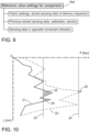
Figure 10 is schematic graph of feed resisting forces in function of movement length on a feed beam. - For the sake of clarity, the figures show some embodiments of the disclosed solution in a simplified manner. In the figures, like reference numerals identify like elements.
-
Figure 1 shows arock drilling rig 1 intended for surface drilling. Therock drilling rig 1 comprises amovable carrier 2 and at least onedrilling boom 3 connected to thecarrier 2. At a distal end portion of thedrilling boom 3 is adrilling unit 4 provided with afeed beam 5 and arock drilling machine 6 supported on it. Adrilling tool 7 is connectable to thedrilling machine 6. Therock drilling machine 6 may comprise a shank adaptor at a front end of therock drilling machine 6 for connecting thedrilling tool 7. Therock drilling machine 6 comprises arotating device 8 for rotating R thedrilling tool 7. Therock drilling machine 6 may also comprise animpact device 9 for providing thedrilling tool 7 with impact pulses. Therock drilling machine 6 is movable on thefeed beam 5 by means of a feed device FD in a drilling direction A and in a reverse direction B. The feed device FD generates feed forces F1 and F2 for executing the feed movements A and B. - Thus, in
Figure 1 therock drilling machine 6 on thefeed beam 5 is a top hammer type device comprising therotating device 8 and theimpact device 9. -
Figure 2 discloses a DTH typerock drilling unit 4 wherein therock drilling machine 6 movable on afeed beam 5 comprises arotating head 19. Animpact device 9 is mounted to a distal end portion of therock drilling tool 7 and is configured to provide a drill bit 11 with impact pulses. In case of rotary drilling, there is noimpact device 10, but the drilling implements only the rotating movement of therock drilling tool 7 including the drill bit 11. - Thus, in
Figure 2 therock drilling machine 6 on thefeed beam 5 is therotation head 19 configured to rotate thedrilling tool 7. -
Figures 1 and 2 illustrate only some exemplary solutions wherein the fee condition testing disclosed in this document can be implemented. This means that the solution is suitable to be used widely for testing different rock drilling units and their feed arrangements. -
Figure 3 shows in views a - e that arock drilling machine 6 can be moved on afeed beam 5 from a first end position (view a) to an opposite second end position (view c) and back to the first end position (view e) when executing feed condition testing. Feed forces F1 and F2 required for moving therock drilling machine 6 in a drilling direction A and on thefeed beam 5 are sensed or measured at desired locations (views b and d) on thefeed beam 5 when implementing the feed condition testing. The sensing locations or distances can be defined in accordance to need. - The
rock drilling machine 6 is moved on thefeed beam 5 idle without executing simultaneous rock drilling. As can be noted, therock drilling machine 6 is typically moved empty on thefeed beam 5 during the testing, i.e., the rock drilling machine is without a drilling tool. -
Figure 4 discloses a control system CS for executing a feed condition testing. Afeed beam 5 may, for example, comprisedamages 12 or the feed beam may be curved 13 so that greater forces F1 and F2 are needed for moving arock drilling machine 6 on thefeed beam 5. The control system CS comprises a control unit CU which is provided with sensing data from several sensors, such as one or more force sensors Sf, positions sensors Sp, and inclination sensors Si. The control unit CU is arranged to control at least a feed device FD and is provided with a drilling mode Md for executing actual rock drilling measures. In order to execute the testing process for the feed system, the control system CS is provided with a feed testing mode Mft, which can be activated under control of an operator or automatically by means of the control unit CU. When the feed testing mode Mft is activated, the actual rock drilling is interrupted and therock drilling machine 6 is moved on thefeed beam 5 at least in one movement direction A, B and simultaneous measuring of feed forces F1, F2 is activated. The measuring data can be stored and processed in the control unit CU. The control unit CU is provided with a processor and a computer program product executable in the processor. The control unit CU can compare the sensing data to stored one or more reference value settings Ref. Thereby changes in condition of thefeed beam 5 can be noted. The control unit CU may be provided with a user interface UI for providing the operator with data on results of the condition testing. Further, the control unit CU can produce compensation or correction values Cor which can be used in the actual rock drilling for compensating detected increased need of the feed forces F1, F2. -
Figure 5 discloses ahydraulic cylinder 14 serving as a feed device FD. Pressure sensors Spr1 and Spr2 can sense pressures prevailing in pressure channels of working pressure spaces of thehydraulic cylinder 14. By means of the gathered pressure data a control unit can determine forces required in moving a rock drilling machine in directions A and B. Magnitudes of the sensed pressures are correlated with magnitudes of the feed forces. -
Figure 6 discloses that input power of a motor M powering a hydraulic pump HP providing hydraulic power for a hydraulic feed device FD is sensed by means of an electrical sensor Se for providing a control unit CU data for feed condition testing purposes. Magnitude of the sensed input power correlates with magnitudes of generated feed forces of the feed device FD. -
Figures 7 and 8 disclose that feed condition testing can be made when afeed beam 5 is moved to a vertical position. However, it can also be implemented in inclined positions and then inclination angle of the feed beam can be sensed by means of inclination sensors Si1 and Si2. Data on feed forces and inclination angles can be transmitted to a control unit CU. In case the feed condition test results are already available of two inclination angle positions, then the control unit CU can interpolate Ex feed forces at any angle of inclination between them. -
Figure 9 discloses some possible reference value setting Ref which can be utilized in feed condition testing process. -
Figure 10 discloses some realized measurement results of a feed condition test process. Afirst curve 21 represents required pressures of a hydraulic feed device in a first movement direction and asecond curve 22 represents required pressures in an opposite second movement direction. The system may be provided with settable limit values 23 and 24 for the pressures and exceeds 25 of these limit values 23, 24 can be indicated on a user interface for operator and service personnel. This kind of maps indicating feed resisting forces and factors at different movement positions can be produced for proving visual and intuitive data on detected condition of the feed beam. - The drawings and the related description are only intended to illustrate the idea of the invention. In its details, the invention may vary within the scope of the claims.
Claims (15)
- A control system (CS) for a rock drilling unit (4) comprising a rock drilling machine (6) mounted on a feed beam (5) and being movable by means of a feed device (FD) in a drilling direction (A) and in a reverse direction (B) on the feed beam (5);wherein the system (CS) comprises at least one control unit (CU) for controlling operation of the feed device (FD) for generating feed forces (F1, F2) for moving the rock drilling machine (6) on the feed beam (5);characterized in thatthe system (CS) comprises a selectable drilling mode (Md) for executing actual rock drilling operation and a selectable feed testing mode (Mft) for feeding the rock drilling machine (6) idle at least in one feed direction (A, B) without simultaneous rock drilling operation;the system (CS) is configured to determine magnitudes of the feed forces (F1, F2) in response to the selected feed testing mode (Mft) for determining feed forces (F1, F2) required for moving the rock drilling machine (6) idle along the feed beam (5);and the system (CS) is configured to compare the determined feed forces (F1, F2) to at least one reference value setting (Ref) for determining factors resisting movements of the rock drilling machine (6) on the feed beam (5).
- The system as claimed in claim 1, characterized in that
the system (CS) is configured to examine the determined feed forces (F1, F2) in function of movement lengths along the feed beam (5). - The system as claimed in claim 1 or 2, characterized in that
the system (CS) is configured to implement the determined sensing values for producing correction values (Cor) for feed requests for controlling the feed device (FD), whereby the system (CS) is configured to compensate the feed forces (F1, F2) during the drilling mode (Md) in response to the data determined on the feed testing mode (Mft) . - The system as claimed in any one of the preceding claims 1 - 3, characterized in that
the system (CS) is configured to move the rock drilling machine (6) in the feed testing mode (Mft) in the drilling direction (A) and in the reverse direction (B) and is configured to determine magnitudes of the feed forces (F1, F2) in both feed directions (A, B) in response to the selected feed testing mode (Mft). - The system as claimed in any one of the preceding claims 1 - 4, characterized in that
the system (CS) is configured to turn the feed beam (5) into vertical position in response to the selection of the feed testing mode (Mft), whereby the testing is executed in the vertical position. - The system as claimed in any one of the claims 1 - 4, characterized in that
the system (CS) is configured to execute the sensing in inclined position of the feed beam (5). - The system as claimed in any one of the preceding claims 1 - 6, characterized in that
the at least one reference value setting (Ref) comprises stored data on at least one previously executed feed testing process. - The system as claimed in any one of the claims 1 - 7, characterized in thatthe system (CS) is provided with sensing data gathered from at least one sensing device configured to monitor operation of the feed device (FD);and the control unit (CU) of the system (CS) is configured to determine the implemented feed forces (F1, F2) in response to the gathered sensing data.
- The system as claimed in claim 8, characterized in that
the system (CS) is configured to monitor feed pressure of a hydraulic feed device (FD). - The system as claimed in claim 8, characterized in that
the system (CS) is configured to monitor input power of a motor (M) powering the feed device (FD). - A rock drilling unit (4), comprising:a feed beam (5);a rock drilling machine (6) mounted movably on the feed beam (5);a feed device (FD) for moving the rock drilling machine (6) in a drilling direction (A) and a reverse direction (B);a control system (CS) for controlling at least the feed device (FD);characterized in thatthe control system (CS) is in accordance with any one of the previous claims 1 - 10.
- The rock drilling unit as claimed in claim 11, characterized in that
the rock drilling machine (6) on the feed beam is a rotation head (19) configured to rotate a drilling tool (7). - The rock drilling unit as claimed in claim 11, characterized in that
the rock drilling machine (6) on the feed beam (5) is a top hammer type device comprising a rotating device (8) and an impact device (9). - A method for controlling feeding of a rock drilling machine (6) on a feed beam (5);
characterized byfeeding the rock drilling machine (6) idle at least in one feed direction (A, B) without simultaneous rock drilling operation;determining magnitudes of feed forces (F1, F2) during the feeding for detecting feed forces (F1, F2) required for moving the rock drilling machine (6) idle along the feed beam (5);and comparing the determined feed forces (F1, F2) to at least one reference value setting (Ref) for determining factors resisting movements of the rock drilling machine (6) on the feed beam (5). - The method as claimed in claim 14, characterized by
generating compensation to feed forces (F1, F2) utilized during an actual rock drilling on the basis of the detected factors resisting the idle feeding of the rock drilling machine (6).
Priority Applications (3)
| Application Number | Priority Date | Filing Date | Title |
|---|---|---|---|
| EP23197347.0A EP4524359B1 (en) | 2023-09-14 | 2023-09-14 | Control system, rock drilling unit, and method |
| PCT/EP2024/073093 WO2025056274A1 (en) | 2023-09-14 | 2024-08-16 | Control system, rock drilling unit, and method |
| AU2024340198A AU2024340198A1 (en) | 2023-09-14 | 2024-08-16 | Control system, rock drilling unit, and method |
Applications Claiming Priority (1)
| Application Number | Priority Date | Filing Date | Title |
|---|---|---|---|
| EP23197347.0A EP4524359B1 (en) | 2023-09-14 | 2023-09-14 | Control system, rock drilling unit, and method |
Publications (3)
| Publication Number | Publication Date |
|---|---|
| EP4524359A1 true EP4524359A1 (en) | 2025-03-19 |
| EP4524359B1 EP4524359B1 (en) | 2026-04-22 |
| EP4524359C0 EP4524359C0 (en) | 2026-04-22 |
Family
ID=88068928
Family Applications (1)
| Application Number | Title | Priority Date | Filing Date |
|---|---|---|---|
| EP23197347.0A Active EP4524359B1 (en) | 2023-09-14 | 2023-09-14 | Control system, rock drilling unit, and method |
Country Status (3)
| Country | Link |
|---|---|
| EP (1) | EP4524359B1 (en) |
| AU (1) | AU2024340198A1 (en) |
| WO (1) | WO2025056274A1 (en) |
Citations (2)
| Publication number | Priority date | Publication date | Assignee | Title |
|---|---|---|---|---|
| WO2003044319A1 (en) * | 2001-11-22 | 2003-05-30 | Atlas Copco Rock Drills Ab | Method of rock drilling |
| WO2021194407A1 (en) * | 2020-03-27 | 2021-09-30 | Epiroc Rock Drills Aktiebolag | A method performed by a control device for controlling the feeding distance and feeding rate in a rock drilling unit, a rock drilling unit and a rock drilling rig |
-
2023
- 2023-09-14 EP EP23197347.0A patent/EP4524359B1/en active Active
-
2024
- 2024-08-16 AU AU2024340198A patent/AU2024340198A1/en active Pending
- 2024-08-16 WO PCT/EP2024/073093 patent/WO2025056274A1/en not_active Ceased
Patent Citations (2)
| Publication number | Priority date | Publication date | Assignee | Title |
|---|---|---|---|---|
| WO2003044319A1 (en) * | 2001-11-22 | 2003-05-30 | Atlas Copco Rock Drills Ab | Method of rock drilling |
| WO2021194407A1 (en) * | 2020-03-27 | 2021-09-30 | Epiroc Rock Drills Aktiebolag | A method performed by a control device for controlling the feeding distance and feeding rate in a rock drilling unit, a rock drilling unit and a rock drilling rig |
Also Published As
| Publication number | Publication date |
|---|---|
| EP4524359B1 (en) | 2026-04-22 |
| EP4524359C0 (en) | 2026-04-22 |
| AU2024340198A1 (en) | 2026-03-12 |
| WO2025056274A1 (en) | 2025-03-20 |
Similar Documents
| Publication | Publication Date | Title |
|---|---|---|
| JP5470394B2 (en) | Control method and structure of rock drill | |
| JP5789374B2 (en) | Rock drilling rig control method and apparatus | |
| AU2003276295A1 (en) | Arrangement for controlling rock drilling | |
| US11391093B2 (en) | Apparatus, rock breaking machine and method of monitoring rock breaking machine | |
| US12006770B2 (en) | Method and system for estimating wear of a drill bit | |
| EP4317615A2 (en) | Systems and methods for measuring forces in earth moving machinery and control thereof, and automatic or semi-automatic machinery | |
| EP1436486A1 (en) | Method and arrangement of controlling of percussive drilling based on the stress level determined from the measured feed rate | |
| EP4524359B1 (en) | Control system, rock drilling unit, and method | |
| JP2023529438A (en) | Accumulator diagnostic method and system in hydraulic circuit | |
| EP4083371B1 (en) | Apparatus and method for controlling flushing in rock drilling | |
| AU2020277234B2 (en) | Automatic force adjustment control system for mobile drilling machines | |
| CN120684182A (en) | A real-time rock strength identification system and method based on PDC drill bit drilling parameters | |
| SE534665C2 (en) | Method, computerized control system, computer program and computer-readable medium for controlling feed rate and drilling rig | |
| CN116547441B (en) | Methods and systems for detecting the condition of drill string joints | |
| JP2015166548A (en) | Rock drill rig control method and device | |
| JP3747281B2 (en) | Wire excavation accuracy controller for ground improvement processing machine | |
| CN114109363A (en) | Drilling while-drilling inclination measuring system | |
| WO2022139654A1 (en) | Method and system for optimising a drilling parameter during an ongoing drilling process | |
| US20230136108A1 (en) | A method performed by a control device for controlling the feeding distance and feeding rate in a rock drilling unit, a rock drilling unit and a rock drilling rig | |
| US12270291B2 (en) | Method for monitoring overburden when advance working in the ground, and advance- working device | |
| KR20230094243A (en) | Power tools | |
| JP2025171700A (en) | Drilling System | |
| JP3865885B2 (en) | Oil quantity detection device for hydraulic cylinder of drilling machine | |
| NO801184L (en) | PROCEDURE AND DEVICE FOR CONTROL OF CURRENT Borehole Depth | |
| AU2002333928A1 (en) | Method and arrangement of controlling of percussive drilling based on the stress level determined from the measured feed rate |
Legal Events
| Date | Code | Title | Description |
|---|---|---|---|
| PUAI | Public reference made under article 153(3) epc to a published international application that has entered the european phase |
Free format text: ORIGINAL CODE: 0009012 |
|
| STAA | Information on the status of an ep patent application or granted ep patent |
Free format text: STATUS: THE APPLICATION HAS BEEN PUBLISHED |
|
| AK | Designated contracting states |
Kind code of ref document: A1 Designated state(s): AL AT BE BG CH CY CZ DE DK EE ES FI FR GB GR HR HU IE IS IT LI LT LU LV MC ME MK MT NL NO PL PT RO RS SE SI SK SM TR |
|
| STAA | Information on the status of an ep patent application or granted ep patent |
Free format text: STATUS: REQUEST FOR EXAMINATION WAS MADE |
|
| 17P | Request for examination filed |
Effective date: 20250919 |
|
| GRAP | Despatch of communication of intention to grant a patent |
Free format text: ORIGINAL CODE: EPIDOSNIGR1 |
|
| STAA | Information on the status of an ep patent application or granted ep patent |
Free format text: STATUS: GRANT OF PATENT IS INTENDED |
|
| INTG | Intention to grant announced |
Effective date: 20260108 |
|
| GRAS | Grant fee paid |
Free format text: ORIGINAL CODE: EPIDOSNIGR3 |
|
| GRAA | (expected) grant |
Free format text: ORIGINAL CODE: 0009210 |
|
| STAA | Information on the status of an ep patent application or granted ep patent |
Free format text: STATUS: THE PATENT HAS BEEN GRANTED |
|
| AK | Designated contracting states |
Kind code of ref document: B1 Designated state(s): AL AT BE BG CH CY CZ DE DK EE ES FI FR GB GR HR HU IE IS IT LI LT LU LV MC ME MK MT NL NO PL PT RO RS SE SI SK SM TR |
|
| REG | Reference to a national code |
Ref country code: CH Ref legal event code: F10 Free format text: ST27 STATUS EVENT CODE: U-0-0-F10-F00 (AS PROVIDED BY THE NATIONAL OFFICE) Effective date: 20260422 Ref country code: GB Ref legal event code: FG4D |
|
| REG | Reference to a national code |
Ref country code: IE Ref legal event code: FG4D |
|
| REG | Reference to a national code |
Ref country code: DE Ref legal event code: R096 Ref document number: 602023015620 Country of ref document: DE |
|
| U01 | Request for unitary effect filed |
Effective date: 20260511 |
|
| U07 | Unitary effect registered |
Designated state(s): AT BE BG DE DK EE FI FR IT LT LU LV MT NL PT RO SE SI Effective date: 20260519 |