EP4524218A1 - Operation method of vertical dry distillation furnace, production method of ferrocoke and vertical dry distillation furnace equipment - Google Patents
Operation method of vertical dry distillation furnace, production method of ferrocoke and vertical dry distillation furnace equipment Download PDFInfo
- Publication number
- EP4524218A1 EP4524218A1 EP23842752.0A EP23842752A EP4524218A1 EP 4524218 A1 EP4524218 A1 EP 4524218A1 EP 23842752 A EP23842752 A EP 23842752A EP 4524218 A1 EP4524218 A1 EP 4524218A1
- Authority
- EP
- European Patent Office
- Prior art keywords
- furnace
- flow rate
- tuyeres
- gas
- carbonization
- Prior art date
- Legal status (The legal status is an assumption and is not a legal conclusion. Google has not performed a legal analysis and makes no representation as to the accuracy of the status listed.)
- Pending
Links
Images




Classifications
-
- C—CHEMISTRY; METALLURGY
- C10—PETROLEUM, GAS OR COKE INDUSTRIES; TECHNICAL GASES CONTAINING CARBON MONOXIDE; FUELS; LUBRICANTS; PEAT
- C10B—DESTRUCTIVE DISTILLATION OF CARBONACEOUS MATERIALS FOR PRODUCTION OF GAS, COKE, TAR, OR SIMILAR MATERIALS
- C10B41/00—Safety devices, e.g. signalling or controlling devices for use in the discharge of coke
-
- C—CHEMISTRY; METALLURGY
- C10—PETROLEUM, GAS OR COKE INDUSTRIES; TECHNICAL GASES CONTAINING CARBON MONOXIDE; FUELS; LUBRICANTS; PEAT
- C10B—DESTRUCTIVE DISTILLATION OF CARBONACEOUS MATERIALS FOR PRODUCTION OF GAS, COKE, TAR, OR SIMILAR MATERIALS
- C10B3/00—Coke ovens with vertical chambers
-
- C—CHEMISTRY; METALLURGY
- C10—PETROLEUM, GAS OR COKE INDUSTRIES; TECHNICAL GASES CONTAINING CARBON MONOXIDE; FUELS; LUBRICANTS; PEAT
- C10B—DESTRUCTIVE DISTILLATION OF CARBONACEOUS MATERIALS FOR PRODUCTION OF GAS, COKE, TAR, OR SIMILAR MATERIALS
- C10B47/00—Destructive distillation of solid carbonaceous materials with indirect heating, e.g. by external combustion
- C10B47/18—Destructive distillation of solid carbonaceous materials with indirect heating, e.g. by external combustion with moving charge
- C10B47/20—Destructive distillation of solid carbonaceous materials with indirect heating, e.g. by external combustion with moving charge according to the moving bed type
-
- C—CHEMISTRY; METALLURGY
- C10—PETROLEUM, GAS OR COKE INDUSTRIES; TECHNICAL GASES CONTAINING CARBON MONOXIDE; FUELS; LUBRICANTS; PEAT
- C10B—DESTRUCTIVE DISTILLATION OF CARBONACEOUS MATERIALS FOR PRODUCTION OF GAS, COKE, TAR, OR SIMILAR MATERIALS
- C10B49/00—Destructive distillation of solid carbonaceous materials by direct heating with heat-carrying agents including the partial combustion of the solid material to be treated
- C10B49/02—Destructive distillation of solid carbonaceous materials by direct heating with heat-carrying agents including the partial combustion of the solid material to be treated with hot gases or vapours, e.g. hot gases obtained by partial combustion of the charge
- C10B49/04—Destructive distillation of solid carbonaceous materials by direct heating with heat-carrying agents including the partial combustion of the solid material to be treated with hot gases or vapours, e.g. hot gases obtained by partial combustion of the charge while moving the solid material to be treated
-
- C—CHEMISTRY; METALLURGY
- C10—PETROLEUM, GAS OR COKE INDUSTRIES; TECHNICAL GASES CONTAINING CARBON MONOXIDE; FUELS; LUBRICANTS; PEAT
- C10B—DESTRUCTIVE DISTILLATION OF CARBONACEOUS MATERIALS FOR PRODUCTION OF GAS, COKE, TAR, OR SIMILAR MATERIALS
- C10B49/00—Destructive distillation of solid carbonaceous materials by direct heating with heat-carrying agents including the partial combustion of the solid material to be treated
- C10B49/02—Destructive distillation of solid carbonaceous materials by direct heating with heat-carrying agents including the partial combustion of the solid material to be treated with hot gases or vapours, e.g. hot gases obtained by partial combustion of the charge
- C10B49/04—Destructive distillation of solid carbonaceous materials by direct heating with heat-carrying agents including the partial combustion of the solid material to be treated with hot gases or vapours, e.g. hot gases obtained by partial combustion of the charge while moving the solid material to be treated
- C10B49/06—Destructive distillation of solid carbonaceous materials by direct heating with heat-carrying agents including the partial combustion of the solid material to be treated with hot gases or vapours, e.g. hot gases obtained by partial combustion of the charge while moving the solid material to be treated according to the moving bed type
-
- C—CHEMISTRY; METALLURGY
- C10—PETROLEUM, GAS OR COKE INDUSTRIES; TECHNICAL GASES CONTAINING CARBON MONOXIDE; FUELS; LUBRICANTS; PEAT
- C10B—DESTRUCTIVE DISTILLATION OF CARBONACEOUS MATERIALS FOR PRODUCTION OF GAS, COKE, TAR, OR SIMILAR MATERIALS
- C10B53/00—Destructive distillation, specially adapted for particular solid raw materials or solid raw materials in special form
- C10B53/08—Destructive distillation, specially adapted for particular solid raw materials or solid raw materials in special form in the form of briquettes, lumps and the like
Definitions
- the present invention relates to a method of operating a vertical carbonization furnace that produces ferro coke, a method of producing ferro coke, and a vertical-carbonization-furnace facility.
- Ferro coke is produced by carbonizing coal, together with an iron-containing substance, such as iron ore, and contains therein metal iron in the form of fine particles produced by reduction of the iron-containing substance.
- the metal iron has the function of a catalyst that accelerates a reaction in which CO 2 produced by the progression of a reaction in a blast furnace reacts with coke (C) and reproduces CO that is a reducing gas. Therefore, when the ferro coke is used, since a gasification reaction of the coke starts from a low-temperature portion in the blast furnace, it is possible to decrease the temperature of a thermal reserve zone.
- An ordinary chamber coke oven consists of silica bricks. Therefore, when iron ore is charged and carbonized, silica, which is a main component of the silica bricks, reacts with iron ore, and fayalite having a low melting point is produced. Since there is a problem in that the silica bricks are damaged by this reaction, the production of ferro coke by using a chamber coke oven of a related art is not industrially carried out. Therefore, as a method of producing ferro coke, a production method using a vertical carbonization furnace is being proposed as an alternative to the production method using a chamber coke oven.
- Fig. 1 is a perspective schematic view of a vertical-carbonization-furnace facility 100 that makes it possible to carry out a method of operating a vertical carbonization furnace according to the embodiment.
- Fig. 2 is a sectional schematic view of a vertical carbonization furnace 10.
- Fig. 2(a) is a sectional view along line A-A of Fig. 1
- Fig. 2(b) is a sectional view along B-B of Fig. 2(a) .
- the vertical-carbonization-furnace facility 100 is a facility that produces ferro coke by carbonizing a molded product that becomes a raw material of the ferro coke.
- the molded product that becomes a raw material of the ferro coke is produced by cold-briquetting with a briquetting machine the molded product out of an iron-containing raw material, such as iron ore, a carbon-containing raw material, such as coal, and a binder-containing raw material.
- the vertical-carbonization-furnace facility 100 includes the vertical carbonization furnace 10, acceleration sensors 20, temperature sensors 30, flow-rate regulating valves 40, and a control device 50.
- the vertical carbonization furnace 10 includes charging port 11, a carbonization-furnace main body 12, high-temperature tuyeres 13, low-temperature tuyeres 14, cooling tuyeres 15, extraction tuyeres 16, and a discharge port 17.
- the charging ports 11 are provided at an upper portion of the carbonization-furnace main body 12. Each charging port 11 is an opening for charging into the carbonization-furnace main body 12 a molded product that becomes a raw material of ferro coke.
- the vertical carbonization furnace 10 includes two charging ports 11.
- the discharge port 17 is provided on a lower end of the carbonization-furnace main body 12. Ferro coke carbonized and produced in the furnace is discharged from the discharge port 17. The ferro coke discharged from the discharge port 17 is conveyed to a product hopper by a conveyor (not shown), and is used as a blast-furnace raw material.
- high-temperature tuyeres 13 in total are provided, four at one of the two furnace walls 12a and four at the other of the two furnace walls 12a.
- Four high-temperature tuyeres 13 are provided at equal intervals at positions at the same height and differing from each other in a width direction.
- a heating device that is provided outside the furnace, for example, high-temperature gas heated to 800°C to 1100°C is blown into the furnace from the high-temperature tuyeres 13. It is preferable that high-temperature gas heated to 900°C to 1000°C be blown into the furnace from the high-temperature tuyeres 13.
- the width direction means a direction in which sides of the horizontal cross section of the carbonization-furnace main body 12 become long sides.
- the control device 50 determines that the vertical carbonization furnace 10 is operationally abnormal, the control device 50 adjusts the flow rate of the gas that is discharged from the extraction tuyere 16 by adjusting the opening of the flow-rate regulating valve 40 such that the flow rate of the gas that is discharged from the extraction tuyere 16 is within the predetermined flow rate range. For example, when the flow rate of gas that is discharged from a particular extraction tuyere 16 exceeds the predetermined flow rate range, the control device 50 narrows the opening of the flow-rate regulating valve 40 of the particular extraction tuyere 16 and decreases the flow rate of the gas that is discharged from the extraction tuyere 16. Therefore, the flow rate of the gas that is discharged from the particular extraction tuyere 16 is decreased and the flow rate of the gas can be caused to be within the predetermined flow rate range.
- the predetermined flow rate range is not limited to the flow rate range of gas, and may be an upper limit of the flow rate of gas or a lower limit of the flow rate of the gas.
- the upper limit it is determined that the flow rate is outside the flow rate range when the upper limit is exceeded.
- the lower limit it is determined that the flow rate is outside the flow rate range when the flow rate is less than the lower limit.
- the upper limit as the predetermined flow rate range is, for example, 114. That is, the control device 50 determines that the furnace is operationally abnormal when the flow rate of gas is greater than 1.14 times the reference flow rate.
- the upper limit is determined from flow-rate increase ranges of gases of the other extraction tuyeres 16 when one extraction tuyere 16 of the eight extraction tuyeres 16 is closed.
- the flow rate range is set taking into consideration a prescribed safety factor. Consequently, even if the flow rate of gas that is discharged from an extraction tuyere 16 is outside the predetermined flow rate range, the temperature difference in the furnace in the horizontal cross section is not necessarily greater than or equal to the predetermined temperature difference. In contrast, it becomes possible to, by detecting an operation abnormality of the vertical carbonization furnace 10 on the basis of the temperature difference in the furnace, more reliably detect an operation abnormality of the vertical carbonization furnace 10.
- the temperature in the furnace is decreased, and when the circulation amount of the gas is decreased, the temperature in the furnace is increased.
- a circulation amount of cooling gas is increased, and thus the temperature in the furnace near the extraction tuyere 16 is decreased.
- the circulation amount of the cooling gas is decreased, and thus a high-temperature molded product passes through, as a result of which the temperature in the furnace near the extraction tuyere 16 is increased.
- Fig. 4 is a schematic view showing flow paths of gases discharged from extraction tuyeres 16. As shown in Fig. 4 , the gases discharged from eight extraction tuyeres 16 merge at one flow path 70 and are discharged. At the flow path 70, as pieces of operation data of the vertical carbonization furnace 10, the pressure of the gas is measured by a pressure sensor 72, the flow rate of the gas is measured by a flow-rate sensor 74, and the temperature of the gas is measured by a temperature sensor 76. The pieces of operation data are output to the control device 50, and are stored in the control device 50.
- the input section 54 is, for example, a keyboard or a touch panel integrated with a display.
- the output section 56 is, for example, an LCD or a CRT display.
- the storage section 58 is, for example, an information recording medium, such as an updatable and recordable flash memory, a built-in hard disk or a hard disk connected to a data communication terminal, or a memory card; or a read-write device for the information recording medium.
- the storage section 58 stores, for example, a program for execution of each function by the control section 52 or data that is used by the program.
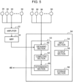
- the pieces of vibration data that are output from the acceleration sensors 20 provided at the respective extraction tuyeres 16 are amplified by an amplifier 22, and low-frequency components are removed by an HPF (high-pass filter) 24.
- the obtaining section 60 obtains the amplified pieces of vibration data whose low-frequency components have been removed and the pieces of identification data of the acceleration sensors 20.
- the obtaining section 60 outputs the obtained pieces of vibration data and the obtained pieces of identification data to the computing section 62.
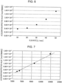
- Fig. 6 is a graph showing the relationship between the acceleration effective value and the gas flow rate.
- the horizontal axis represents the flow rate (L/min) and the vertical axis represents the acceleration effective value (m/s 2 ).
- the acceleration effective value increases as the gas flow rate increases. From this result, it was confirmed that there was a correlation between the gas flow rate and the acceleration effective value.
- Fig. 7 is a graph showing the relationship between the acceleration effective value and the total flow rate in the extraction tuyeres 16.
- the horizontal axis represents the total flow rate (L/min) and the vertical axis represents the acceleration effective value (m/s 2 ).
- the acceleration effective value is the total value of the effective values of vibrations measured at the eight acceleration sensors 20 shown in Fig. 4 . As shown in Fig. 7 , it was confirmed that the acceleration effective value increased in proportion to the total flow rate.
- the computing section 62 is capable of calculating the flow rate of the gas discharged from each extraction tuyere 16 by using the acceleration effective value and the regression equation.
- the computing section 62 outputs the gas flow rate calculated in this way to the determining section 64.
- the vibration data that is output from each acceleration sensor 20 includes not only the vibration caused by the gas that is discharged from each extraction tuyere 16, but also the vibration of the carbonization-furnace main body 12. Since the frequency of the vibration of the carbonization-furnace main body 12 often appears in a low frequency band, for example, by removing a low frequency component of the vibration data by the HPF 24 described above, calculation precision of the gas flow rate is increased.
- the HPF 24 is an example of a disturbance removing filter that removes a frequency component of the vibration that becomes a disturbance.
- the vibration data that is output from each acceleration sensor 20 includes not only the vibration of gas but also vibration that becomes a disturbance of, for example, a peripheral facility. Therefore, when the vibration data is used as it is, the calculation precision of the gas flow rate may be reduced. Consequently, the vibration obtained by varying the production amount of ferro coke so as to change the flow rate of gas discharged from each extraction tuyere 16 and the vibration that became a disturbance, and vibration obtained by changing the vibration that became a disturbance, such as the vibration of a peripheral facility, without discharging the gas were measured.
- the existence ratio of a high correlation coefficient means a ratio obtained when a signal intensity is analyzed for every 1 Hz in a range of up to 12.5 kHz by the frequency analysis, the obtained frequency analysis data is subjected to principal component analysis, and the loading of a first principal component becomes greater than or equal to 0.7 for every 100 Hz.
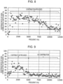
- Fig. 8 is a graph showing the existence ratio of a high correlation coefficient of gas and vibration that becomes a disturbance.
- Fig. 9 is a graph showing the existence ratio of a high correlation coefficient of vibration that becomes a disturbance.
- the horizontal axis represents the frequency (Hz) and the vertical axis represents the existence ratio of a high correlation coefficient (%).
- the high correlation coefficient in which the loading of the first principal component becomes greater than or equal to 0.7 existed over an entire frequency band. From this result, it was confirmed that a wide frequency component contributed to the vibration of the gas and the vibration that became a disturbance.
- the high correlation coefficient in which the loading of the first principal component became greater than or equal to 0.7 existed in a frequency band of less than or equal to 5 kHz and did not exist much in a frequency band greater than 5 kHz. From this result, it was confirmed that the frequency component less than or equal to 5 kHz contributed to the vibration that became a disturbance.
- the loading of 0.7 of the first principal component which is a high correlation value, is an example of a predetermined principal component loading.
- the frequency component of less than or equal to 5 kHz contributes to the vibration that becomes a disturbance
- the frequency component of less than or equal to 5 kHz in the vibration data is removed by using the HPF 24
- the influence of the vibration that becomes a disturbance is reduced, and thus the calculation precision of the gas flow rate is increased.
- the frequency components obtained by frequency analysis of the vibration that becomes a disturbance and is not correlated with the gas flow rate, are subjected to principal component analysis in advance, and the existence ratio in which the loading of the first principal component becomes greater than or equal to a predetermined value is evaluated for every frequency. Therefore, it is possible to previously determine a frequency component that contributes to the vibration that becomes a disturbance and to remove the frequency component from the vibration data by using a disturbance removing filter, as a result of which it is possible to increase the calculation precision of the gas flow rate.
- the frequency component of less than or equal to 5 kHz that becomes a disturbance is removed by using the HPE 24
- the frequency component of the vibration that becomes a disturbance may change due to the type of peripheral facility and the size of the facility. Therefore, the disturbance removing filter that removes the frequency component of the vibration that becomes a disturbance is not limited to the HPE, and may be a bandpass filter or a low-pass filter that removes a prescribed frequency component.
- the principal component whose loading is to be evaluated is not limited to the first principal component, and a second and subsequent principal components may be evaluated. It is only necessary to evaluate the principal component loading that is correlated with the vibration that becomes a disturbance.
- the determining section 64 determines whether or not the gas flow rate obtained from the computing section 62 is outside a predetermined flow rate range.
- the predetermined flow rate range is previously determined by using the flow rate of gas that is discharged from each extraction tuyere 16 in a normal operation state and the flow rate of gas that is discharged from each extraction tuyere 16 when the gas permeability balance is experimentally lost such that the temperature difference in the furnace in the width direction becomes 50°C; and the predetermined flow rate range is stored in the storage section 58.
- the determining section 64 reads out the predetermined flow rate range from the storage section 58, and determines whether or not the gas flow rate obtained from the computing section 62 is outside the predetermined flow rate range. When the gas flow rate obtained from the computing section 62 is outside the predetermined flow rate range, the determining section 64 determines that an operation abnormality caused by a loss of a gas permeability balance in the furnace is occurring. On the other hand, when the gas flow rate obtained from the computing section 62 is within the predetermined flow rate range, the computing section 62 determines that an operation abnormality caused by a loss of a gas permeability balance in the furnace is not occurring.
- the output section 56 may be caused to display an image indicating that an operation abnormality is occurring.
- the vertical-carbonization-furnace facility 100 detects an operation abnormality of the vertical carbonization furnace 10 caused by a loss of a gas permeability balance in the furnace.
- the determining section 64 determines that an operation abnormality caused by a loss of a gas permeability balance in the furnace is occurring, it is preferable that the determining section 64 adjust the opening of a flow-rate regulating value 40 and adjust the flow rate of gas that is discharged from an extraction tuyere 16.
- the determining section 64 reads out a table indicating a correspondence relationship between a setting position and identification data stored in the storage section 58, refers to the table, and determines the setting position of the particular extraction tuyere 16.
- the determining section 64 adjusts the opening of a flow-rate regulating valve 40 to adjust the flow rate of gas discharged from an extraction tuyere 16 where the gas flow rate has fallen outside the predetermined flow rate range (Step S105).
- This processing operation corresponds to an adjusting step.
- control device 50 is capable of detecting an operation abnormality caused by a loss of a gas permeability balance in the vertical carbonization furnace 10. Further, the control section 50 is capable of adjusting the flow rates of gases of gases that are discharged from the extraction tuyeres 16 so as to eliminate the operation abnormality.
- Fig. 11 is a flowchart showing another example of a process of the method of operating the vertical carbonization furnace according to the embodiment.
- the process of detecting an operation abnormality of the vertical carbonization furnace 10 from a gas flow rate and the temperature in the furnace and eliminating the operation abnormality is described.
- the input section 54 starts operating on the condition that the input section 54 has accepted an input from an operator for starting control using the control device 50.
- the obtaining section 60 obtains vibration data from each acceleration sensor 20, and obtains temperature data from each temperature sensor 30 (Step S201). This processing operation corresponds to an obtaining step.
- the obtaining section 60 outputs the obtained pieces of vibration data and the obtained pieces of temperature data to the computing section 62.
- the computing section 62 converts the obtained pieces of vibration data into acceleration effective values and uses the acceleration effective values and the regression equation indicating a correspondence relationship between the acceleration effective values and the gas flow rates, to thereby calculate the flow rate of gas that is discharged from each extraction tuyere 16. Further, the computing section 62 calculates a temperature difference using the obtained pieces of temperature data (Step S202). The computing section 62 outputs the gas flow rates and the temperature difference to the determining section 64.
- the determining section 64 adjusts the opening of a flow-rate regulating valve 40 to adjust, for example, the flow rate of gas discharged from an extraction tuyere 16 that is provided at a position that corresponds to the position in the width direction of a temperature sensor 30 that has outputted the highest temperature data (Step S206).
- This processing operation corresponds to an adjusting step.
- the determining section 64 determines whether or not the input section 54 has received an input from the operator for ending control by the control device 50 (Step S207).
- the determining section 64 ends a processing operation of detecting an operation abnormality of the vertical carbonization furnace 10 and eliminating the operation abnormality.
- the determining section 64 returns to the processing operation of Step S201, and repeats the processing operations from Step S102.
- the control device 50 is capable of detecting an operation abnormality of the vertical carbonization furnace 10 based on an operation abnormality in which a carbonization failure where the temperature difference in the furnace in the horizontal cross section is greater than or equal to 50°C may occur.
- the control device 50 is capable to adjusting the flow rate of gas that is discharged from an extraction tuyere 16 so as to eliminate the operation abnormality.
- the vertical-carbonization-furnace facility 100 detects an operation abnormality of the vertical carbonization furnace 10 caused by a loss of a gas permeability balance in the furnace.
- measures to restore the gas permeability balance in the furnace such as adjusting a flow-rate regulating valve 40, can be taken to thereby make it possible to suppress production of ferro coke having low strength caused by carbonization failure and to thereby make it possible to suppress generation of heat or ignition from occurring in a product hopper.
- the gas permeability balance in the furnace can be restored without changing the amount of heat that is introduced from the high-temperature tuyeres 13 and the low-temperature tuyeres 14, it is possible to maintain a proper production temperature and to suppress deformation or cracking of a molded product.
- the vertical-carbonization-furnace facility 100 has been described using the vertical carbonization furnace 10 including eight high-temperature tuyeres 13, eight low-temperature tuyeres 14, eight extraction tuyeres 16, and eight cooling tuyeres 15, the vertical-carbonization-furnace facility 100 is not limited thereto.
- the vertical carbonization furnace 10 need not include low-temperature tuyeres 14 and cooling tuyeres 15, and only needs to include one or more high-temperature tuyeres 13 or two or more extraction tuyeres 16.
- the extraction tuyeres 16 are not limited thereto.
- the extraction tuyeres 16 need not be provided at the same height or need not be provided at equal intervals. In this way, when the extraction tuyeres 16 are not provided at the same height or at equal intervals, since the flow rate range for determining an operation abnormality differs for each extraction tuyere, the gas flow rate during normal operation and the gas flow rate during abnormal operation are determined for each extraction tuyere 16, and the flow rate range that makes it possible to determine whether or not an operation abnormality has occurred is previously determined for each extraction tuyere 16.
- the flow rate sensors are not limited thereto. As long as the flow rate sensors are capable of measuring the flow rates of gases that are discharged from the extraction tuyeres 16, any type of flow rate sensor may be used. Note that when the data that is output from each flow rate sensor is flow rate data, the computing section 62 outputs the flow rate data obtained from the obtaining section 60 as it is to the determining section 64.
- thermocouple temperature sensors 30 were set at positions corresponding to each other in a horizontal direction near the extraction tuyeres 16.
- acceleration sensors 20 were set at the eight extraction tuyeres 16, and as flow-rate regulating devices, flow-rate regulating valves were set.
- Fig. 12 is a graph showing changes in temperatures in a furnace at units A and B.
- the horizontal axis represents time (hr) and the vertical axis represents the temperature (°C) in the furnace.
- the unit A is one of the four extraction tuyeres provided at the same furnace wall 12a, and the unit B is another one of the four extraction tuyeres.
- the flow rate of gas discharged from the unit A decreased and the temperature in the furnace increased, and at a little past 9:00, the flow rate difference between the gas of the unit A and gas of the unit B fell outside a predetermined range and the temperature difference in the furnace became 50°C.
- the opening of the flow-rate regulating valve provided at the unit A was widened and the flow rate of the gas discharged from the unit A was increased. Consequently, the temperature in the furnace at the unit A decreased, and the temperature difference in the furnace at the units A and B decreased. As a result, the flow rate difference between the gas at the unit A and the gas at the unit B fell within the predetermined range, and the temperature difference of the furnace became less than 50°C, as a result of which it was possible to eliminate an operation failure of the vertical carbonization furnace 10.
Landscapes
- Chemical & Material Sciences (AREA)
- Engineering & Computer Science (AREA)
- Oil, Petroleum & Natural Gas (AREA)
- Materials Engineering (AREA)
- Organic Chemistry (AREA)
- Combustion & Propulsion (AREA)
- Chemical Kinetics & Catalysis (AREA)
- General Chemical & Material Sciences (AREA)
- Coke Industry (AREA)
- Waste-Gas Treatment And Other Accessory Devices For Furnaces (AREA)
- Vertical, Hearth, Or Arc Furnaces (AREA)
Abstract

Description
- The present invention relates to a method of operating a vertical carbonization furnace that produces ferro coke, a method of producing ferro coke, and a vertical-carbonization-furnace facility.
- Ferro coke is produced by carbonizing coal, together with an iron-containing substance, such as iron ore, and contains therein metal iron in the form of fine particles produced by reduction of the iron-containing substance. The metal iron has the function of a catalyst that accelerates a reaction in which CO2 produced by the progression of a reaction in a blast furnace reacts with coke (C) and reproduces CO that is a reducing gas. Therefore, when the ferro coke is used, since a gasification reaction of the coke starts from a low-temperature portion in the blast furnace, it is possible to decrease the temperature of a thermal reserve zone. Consequently, it is thought that it is possible to, by largely decreasing a reducing agent ratio by using the ferro coke, contribute to energy conservation and to a reduction in the emission of CO2. Due to such usefulness, research regarding a ferro coke production technology is progressing.
- An ordinary chamber coke oven consists of silica bricks. Therefore, when iron ore is charged and carbonized, silica, which is a main component of the silica bricks, reacts with iron ore, and fayalite having a low melting point is produced. Since there is a problem in that the silica bricks are damaged by this reaction, the production of ferro coke by using a chamber coke oven of a related art is not industrially carried out. Therefore, as a method of producing ferro coke, a production method using a vertical carbonization furnace is being proposed as an alternative to the production method using a chamber coke oven.
- In this production method, a vertical carbonization furnace that is formed from chamotte bricks instead of silica bricks is used. Coal and iron ore, which are raw materials, are formed into a molded product obtained by mixing the coal and the iron ore with a binder and molding them into a predetermined size, and then the molded product is charged into the vertical carbonization furnace. Then, heat transfer gas is blown into the vertical furnace for heating, to thereby carbonize the molded product and produce molded ferro coke. It is possible to, by using this method, evenly carbonize molded charcoal without damaging the bricks by the iron ore.
- As a vertical carbonization furnace that is used in producing ferro coke, Patent Literature 1 discloses a vertical carbonization furnace that is capable of evenly heating a molded product by controlling the flow of high-temperature gas by providing a gas discharge port in a carbonization-furnace main body.
- Patent Literature 2 discloses a heating rate designing method for carbonizing a molded product under an optimal heating condition. According to Patent Literature 2, it is possible to, by carbonizing the molded product by using an optimal heat pattern, prevent cracking or heat cracking of the molded product occurring during the carbonization and suppress quality deterioration of the ferro coke.
-
- PTL 1:
Japanese Patent No. 6274126 - PTL 2:
Japanese Patent No. 5087868 - When fine powder becomes mixed in a vertical carbonization furnace, since a gas permeability balance in the furnace is lost, it no longer becomes possible to control the flow of high-temperature gas even if the gas discharge port is provided. Similarly, when the gas permeability balance in the furnace is lost due to the mixing of the fine powder, it no longer becomes possible to control even the heat pattern. When the temperature difference in the furnace in a horizontal direction becomes large due to the loss of the gas permeability balance in the furnace, carbonization failure of the molded product carbonized in a low temperature region occurs, and ferro coke that has low strength and that thus can no longer be used as a blast-furnace raw material is produced.
- The present invention has been made in view of such problems of the related art, and it is an object of the present invention to provide a method of operating a vertical carbonization furnace that is capable of detecting an operation abnormality of the vertical carbonization furnace caused by a loss of a gas permeability balance in the furnace, a method of producing ferro coke, and a control device of the vertical carbonization furnace.
- The spirit of the present invention that is capable of solving the problems above is as follows.
- [1] A method of operating a vertical carbonization furnace that produces ferro coke is a method in which the vertical carbonization furnace includes a carbonization-furnace main body; one or more high-temperature tuyeres that blow high-temperature gas into the carbonization-furnace main body; and two or more extraction tuyeres that are provided at positions differing in a height direction from a position of the one or more high-temperature tuyeres, and that discharge gas in the carbonization-furnace main body, and in which the two or more extraction tuyeres are provided at positions at a same height and differing from each other in a width direction, the method of operating the vertical carbonization furnace including an obtaining step of obtaining a flow rate of the gas that is discharged from each of the extraction tuyeres; and a determining step of determining that an operation abnormality has occurred when the flow rate obtained in the obtaining step falls outside a predetermined flow rate range.
- [2] In the method of operating the vertical carbonization furnace according to [1], in the obtaining step, by measuring vibration of each of the extraction tuyeres, the flow rate of the gas that is discharged from each of the extraction tuyeres is obtained.
- [3] In the method of operating the vertical carbonization furnace according to [2], in the obtaining step, the flow rate of the gas that is discharged from each of the extraction tuyeres is obtained from each of the vibrations whose frequency component of vibration that becomes a disturbance is removed, and the frequency component of the vibration that becomes the disturbance is determined by previously performing principal component analysis of the frequency component of the vibration that becomes the disturbance and by determining a principal component loading.
- [4] In the method of operating the vertical carbonization furnace according to [3], the frequency component of the vibration that becomes the disturbance is determined by evaluating for every frequency an existence ratio in which the principal component loading determined by the analysis in terms of the principal component becomes greater than or equal to a predetermined value.
- [5] In the method of operating the vertical carbonization furnace according to any one of [1] to [4], in the obtaining step, temperatures in the furnace at two or more positions that are same in the height direction and that differ from each other in the width direction are further obtained, and that an operation abnormality has occurred is determined when a difference between the temperatures in the furnace is greater than or equal to a predetermined temperature difference.
- [6] The method of operating the vertical carbonization furnace according to any one of [1] to [5], further includes an adjusting step of, when it is determined that an operation abnormality has occurred in the determining step, adjusting the flow rate of the gas that is discharged from each of the extraction tuyeres such that the flow rate falls within the predetermined flow rate range.
- [7] A method of producing ferro coke is a method in which the ferro coke is produced by operating a vertical carbonization furnace by the method of operating the vertical carbonization furnace according to [6].
- [8] A vertical-carbonization-furnace facility that produces ferro coke includes a vertical carbonization furnace; two or more flow rate sensors that measure flow rates of gas; and a control device that controls the vertical carbonization furnace, in which the vertical carbonization furnace includes a carbonization-furnace main body; a charging port into which a molded product that becomes a raw material of the ferro coke is charged; one or more high-temperature tuyeres that blow high-temperature gas into the carbonization-furnace main body; two or more extraction tuyeres that are provided at positions differing in a height direction from a position of the one or more high-temperature tuyeres, and that discharge gas in the carbonization-furnace main body; and a discharge port that discharges the molded product that has been carbonized, in which the two or more extraction tuyeres are provided at positions differing from each other in a width direction, in which the two or more flow rate sensors are each provided at a corresponding one of the two or more extraction tuyeres, and in which the control device includes an obtaining section that obtains from each of the flow rate sensors data indicating the flow rate of the gas that is discharged from each of the extraction tuyeres, a computing section that calculates from the data the flow rate of the gas that is discharged from each of the extraction tuyeres, and a determining section that determines that an operation abnormality has occurred when the flow rate falls outside a predetermined flow rate range.
- [9] In the vertical-carbonization-furnace facility according to [8], each of the flow rate sensors is a vibration meter.
- [10] The vertical-carbonization-furnace facility according to [9], further includes a disturbance removing filter, in which the disturbance removing filter removes a predetermined frequency component of vibration measured by each of the vibration meters.
- [11] In the vertical-carbonization-furnace facility according to [10], the frequency component is previously determined by performing principal component analysis of a frequency component of vibration that becomes a disturbance and by evaluating for every frequency an existence ratio in which a principal component loading becomes greater than or equal to a predetermined value.
- [12] The vertical-carbonization-furnace facility according to any one of [8] to [11], further includes two or more temperature sensors that measure temperatures in the furnace, in which the two or more temperature sensors are provided at positions at a same height in the vertical carbonization furnace and differing from each other in the width direction, and in which the obtaining section obtains the temperature in the furnace from each of the temperature sensors and the determining section determines that an operation abnormality has occurred when a difference between the temperatures in the furnace obtained from the temperature sensors is greater than or equal to a predetermined temperature difference.
- [13] In the vertical-carbonization-furnace facility according to any one of [8] to [12], when the determining section determines that an operation abnormality has occurred, the determining section adjusts the flow rate of the gas that is discharged from each of the extraction tuyeres such that the flow rate falls within the predetermined flow rate range.
- It is possible to, by carrying out the method of operating the vertical carbonization furnace according to the present invention, detect an operation abnormality of the vertical carbonization furnace caused by a loss of a gas permeability balance in the furnace. In this way, when an operation abnormality of the vertical carbonization furnace can be detected, measures to restore the gas permeability balance in the furnace can be taken to thereby make it possible to suppress production of ferro coke having low strength caused by carbonization failure.
-
- [
Fig. 1] Fig. 1 is a perspective schematic view of a vertical-carbonization-furnace facility 100 that makes it possible to carry out a method of operating a vertical carbonization furnace according to an embodiment. - [
Fig. 2] Fig. 2 is a sectional schematic view of avertical carbonization furnace 10. - [
Fig. 3] Fig. 3 is a sectional schematic view of anextraction tuyere 16. - [
Fig. 4] Fig. 4 is a schematic view showing flow paths of gases discharged fromextraction tuyeres 16. - [
Fig. 5] Fig. 5 is a block diagram showing a structure of acontrol device 50. - [
Fig. 6] Fig. 6 is a graph showing the relationship between an acceleration effective value and a gas flow rate. - [
Fig. 7] Fig. 7 is a graph showing the relationship between an acceleration effective value and a total flow rate in theextraction tuyeres 16. - [
Fig. 8] Fig. 8 is a graph showing an existence ratio of a high correlation coefficient of gas and vibration that becomes a disturbance. - [
Fig. 9] Fig. 9 is a graph showing an existence ratio of a high correlation coefficient of vibration that becomes a disturbance. - [
Fig. 10] Fig. 10 is a flowchart showing an example of a process of the method of operating the vertical carbonization furnace according to the embodiment. - [
Fig. 11] Fig. 11 is a flowchart showing another example of a process of the method of operating the vertical carbonization furnace according to the embodiment. - [
Fig. 12] Fig. 12 is a graph showing changes in temperatures in a furnace at units A and B. - The present invention is described below by way of an embodiment of the present invention.
Fig. 1 is a perspective schematic view of a vertical-carbonization-furnace facility 100 that makes it possible to carry out a method of operating a vertical carbonization furnace according to the embodiment.Fig. 2 is a sectional schematic view of avertical carbonization furnace 10.Fig. 2(a) is a sectional view along line A-A ofFig. 1, and Fig. 2(b) is a sectional view along B-B ofFig. 2(a) . - The vertical-carbonization-
furnace facility 100 is a facility that produces ferro coke by carbonizing a molded product that becomes a raw material of the ferro coke. The molded product that becomes a raw material of the ferro coke is produced by cold-briquetting with a briquetting machine the molded product out of an iron-containing raw material, such as iron ore, a carbon-containing raw material, such as coal, and a binder-containing raw material. - As shown in
Figs. 1 and 2 , the vertical-carbonization-furnace facility 100 includes thevertical carbonization furnace 10,acceleration sensors 20,temperature sensors 30, flow-rate regulating valves 40, and acontrol device 50. Thevertical carbonization furnace 10 includes chargingport 11, a carbonization-furnacemain body 12, high-temperature tuyeres 13, low-temperature tuyeres 14, coolingtuyeres 15,extraction tuyeres 16, and adischarge port 17. The chargingports 11 are provided at an upper portion of the carbonization-furnacemain body 12. Each chargingport 11 is an opening for charging into the carbonization-furnacemain body 12 a molded product that becomes a raw material of ferro coke. Thevertical carbonization furnace 10 includes two chargingports 11. - The carbonization-furnace
main body 12 is a furnace whose horizontal cross section has a rectangular cylindrical shape, and includes twofurnace walls 12a that are provided at positions of long sides of the horizontal cross section, and twofurnace walls 12b that are provided at positions of short sides of the horizontal cross section. A refractory is provided on inner sides of thefurnace walls furnace walls - The
discharge port 17 is provided on a lower end of the carbonization-furnacemain body 12. Ferro coke carbonized and produced in the furnace is discharged from thedischarge port 17. The ferro coke discharged from thedischarge port 17 is conveyed to a product hopper by a conveyor (not shown), and is used as a blast-furnace raw material. - Eight high-
temperature tuyeres 13 in total are provided, four at one of the twofurnace walls 12a and four at the other of the twofurnace walls 12a. Four high-temperature tuyeres 13 are provided at equal intervals at positions at the same height and differing from each other in a width direction. By using a heating device that is provided outside the furnace, for example, high-temperature gas heated to 800°C to 1100°C is blown into the furnace from the high-temperature tuyeres 13. It is preferable that high-temperature gas heated to 900°C to 1000°C be blown into the furnace from the high-temperature tuyeres 13. Note that, in the present embodiment, the width direction means a direction in which sides of the horizontal cross section of the carbonization-furnacemain body 12 become long sides. - Eight low-
temperature tuyeres 14 in total are provided at positions corresponding to the positions of the high-temperature tuyeres 13 in the width direction of the twofurnace walls 12a, four at one of the twofurnace walls 12a and four at the other of the twofurnace walls 12a so as to be situated above the high-temperature tuyeres 13 in a height direction. By using a heating device that is provided outside the furnace, for example, low-temperature gas heated to 400°C to 700°C is blown into the furnace from the low-temperature tuyeres 14. In this way, the high-temperature tuyeres 13 and the low-temperature tuyeres 14 are provided in two positions above and below each other at thevertical carbonization furnace 10, and high-temperature gas and low-temperature gas are blown in from these tuyeres. Therefore, compared with a case in which high-temperature gas is blown in from one position of high-temperature tuyeres, it is possible to heat a molded product in a wide range and the vertical carbonization furnace becomes a furnace that is capable of efficiently carbonizing a molded product. - Eight cooling
tuyeres 15 in total are provided near thedischarge port 17, four at one of the twofurnace walls 12a and four at the other of the twofurnace walls 12a. Cooling gas of 25°C to 80°C is blown into the furnace from the coolingtuyeres 15. In this way, it is possible to, by blowing in the cooling gas from the coolingtuyeres 15, decrease the temperature of the carbonized ferro coke that is discharged from thedischarge port 17, and thus continuously carbonize the molded product. When the temperature of the ferro coke can be decreased in this way, it is no longer necessary to provide a cooling facility that cools the ferro coke, and thus it is possible to reduce facility costs of the cooling facility and transportation costs for transporting the ferro coke to the cooling facility. - Eight
extraction tuyeres 16 in total are provided at positions corresponding to the positions of the high-temperature tuyeres 13 in the width direction of the twofurnace walls 12a, four at one of the twofurnace walls 12a and four at the other of the twofurnace walls 12a so as to be situated between the cooling tuyeres 15 and the high-temperature tuyeres 13 in the height direction. Gas of 0°C to 500°C at which the high-temperature gas, the low-temperature gas, and the cooling gas have merged, is discharged to the outside of the furnace from theextraction tuyeres 16. In this way, by providing the high-temperature tuyeres 13, the low-temperature tuyeres 14, and theextraction tuyeres 16 at equal intervals at positions that differ from each other in the width direction of the twofurnace walls 12a such that they face each other, the temperature in the furnace in the horizontal cross section in the carbonization-furnacemain body 12 is made uniform. -
Fig. 3 is a sectional schematic view of anextraction tuyere 16. The flow-rate regulating valves 40 are provided at end portions of therespective extraction tuyeres 16. By adjusting the openings of the flow-rate regulating valves 40, the flow rates of gases that are discharged from theextraction tuyeres 16 are adjusted. Two branchingportions 19 are provided at eachextraction tuyere 16. By providing two branchingportions 19, dust or foreign substances contained in the gas that is discharged from eachextraction tuyere 16 can be separated into the branchingportions 19. - Each
acceleration sensor 20 is provided at an outer wall surface of itscorresponding extraction tuyere 16. Eachacceleration sensor 20 measures vibration data of the outer wall surface of itscorresponding extraction tuyere 16 as data indicating the flow rate of the gas that is discharged from itscorresponding extraction tuyere 16. Eachacceleration sensor 20 outputs to thecontrol device 50 the measured vibration data together with identification data of the acceleration sensor. Note that, in the present embodiment, eachacceleration sensor 20 is one example of a vibration meter. -
Fig. 2 is referred to again. Eighttemperature sensors 30 in total are provided at inner wall surfaces of the twofurnace walls 12a at equal intervals so as to be situated at positions at the same height and differing from each other in the width direction. In the example shown inFig. 2 , thetemperature sensors 30 are provided at positions corresponding to the positions of theextraction tuyeres 16 in the width direction so as to be situated near theextraction tuyeres 16. Eachtemperature sensor 30 measures the temperature of the inside of the furnace at its corresponding position, and outputs to thecontrol device 50 the measured temperature data together with identification data of the temperature sensor. Note that the positions where thetemperature sensors 30 are provided are not limited to positions near theextraction tuyeres 16. Thetemperature sensors 30 may be provided at positions in the carbonization-furnacemain body 12 that differ from each other in the height direction. - The
control device 50 obtains the data indicating the flow rate of the gas from eachacceleration sensor 20, and calculates the flow rate of the gas that is discharged from eachextraction tuyere 16 from this data. Thecontrol device 50 determines whether or not each calculated flow rate of the gas is outside a predetermined flow rate range. - When the gas permeability of a part of a region in the
vertical carbonization furnace 10 deteriorates and the gas permeability balance in the furnace is lost, the flow of gas that is discharged from anextraction tuyere 16 provided at a position in the width direction that corresponds to the region where the gas permeability has deteriorated is decreased, and the flow rates of gases that are discharged from theother extraction tuyeres 16 are increased. Therefore, it is possible to, by determining whether or not the flow rate of the gas that is discharged from theextraction tuyere 16 is outside the predetermined flow rate range, detect an operation abnormality of thevertical carbonization furnace 10 caused by the loss of the gas permeability balance in the furnace. Note that the predetermined flow rate range is determined to be a flow rate range in which a temperature difference in the furnace in a horizontal direction can be maintained to be less than 50°C by using a flow rate of gas that is discharged from anextraction tuyere 16 in a normal operation state and a flow rate of gas that is discharged from theextraction tuyere 16 when the gas permeability balance is experimentally lost and the temperature difference in the furnace in the horizontal direction becomes 50°C. - The
control device 50 determines that thevertical carbonization furnace 10 is operationally abnormal when the flow rate of gas that is discharged from anextraction tuyere 16 is outside the predetermined flow rate range. On the other hand, thecontrol device 50 determines that thevertical carbonization furnace 10 is operationally normal when the flow rate of the gas that is discharged from theextraction tuyere 16 is within the predetermined flow rate range. Therefore, thecontrol device 50 is capable of detecting an operation abnormality of thevertical carbonization furnace 10 caused by the loss of the gas permeability balance in the furnace. - When the
control device 50 determines that thevertical carbonization furnace 10 is operationally abnormal, thecontrol device 50 adjusts the flow rate of the gas that is discharged from theextraction tuyere 16 by adjusting the opening of the flow-rate regulating valve 40 such that the flow rate of the gas that is discharged from theextraction tuyere 16 is within the predetermined flow rate range. For example, when the flow rate of gas that is discharged from aparticular extraction tuyere 16 exceeds the predetermined flow rate range, thecontrol device 50 narrows the opening of the flow-rate regulating valve 40 of theparticular extraction tuyere 16 and decreases the flow rate of the gas that is discharged from theextraction tuyere 16. Therefore, the flow rate of the gas that is discharged from theparticular extraction tuyere 16 is decreased and the flow rate of the gas can be caused to be within the predetermined flow rate range. - Note that the predetermined flow rate range is not limited to the flow rate range of gas, and may be an upper limit of the flow rate of gas or a lower limit of the flow rate of the gas. When the upper limit is determined, it is determined that the flow rate is outside the flow rate range when the upper limit is exceeded. When the lower limit is determined, it is determined that the flow rate is outside the flow rate range when the flow rate is less than the lower limit. Note that, when the flow rate (reference flow rate) of gas that is discharged from an
extraction tuyere 16 during normal operation is 100, the upper limit as the predetermined flow rate range is, for example, 114. That is, thecontrol device 50 determines that the furnace is operationally abnormal when the flow rate of gas is greater than 1.14 times the reference flow rate. Note that the upper limit is determined from flow-rate increase ranges of gases of theother extraction tuyeres 16 when oneextraction tuyere 16 of the eightextraction tuyeres 16 is closed. - When the flow rate of gas that is discharged from an
extraction tuyere 16 is less than the predetermined flow rate range, thecontrol device 50 widens the opening of the flow-rate regulating valve 40 and increases the flow rate of the gas that is discharged from theextraction tuyere 16. Therefore, the flow rate of gas that is discharged from aparticular extraction tuyere 16 is increased, and the flow rate can be caused to be within the predetermined flow rate range. - The
control device 50 may obtain the temperatures in the furnace from thetemperature sensors 30. Thecontrol device 50 may determine that the furnace is operationally abnormal when a temperature difference in the furnace obtained from thetemperature sensors 30 provided at the same height is greater than or equal to a predetermined temperature difference. That is, in this case, thecontrol device 50 may determine that thevertical carbonization furnace 10 is operationally abnormal when the gas flow rate is outside the predetermined flow rate range and the temperature difference in the furnace is greater than or equal to the predetermined temperature difference. Note that, in the present embodiment, the predetermined temperature difference is, for example, 50°C. - When the temperature difference in the furnace in a horizontal method of a lower portion of the furnace becomes greater than or equal to 50°C, uneven cooling of a molded product occurs, and high-temperature ferro coke is discharged from the
discharge port 17 and thus generation of heat or ignition may occur in a product hopper. Therefore, in order to reliably maintain at less than 50°C the temperature difference in the furnace in a horizontal cross section, the flow rate range is set taking into consideration a prescribed safety factor. Consequently, even if the flow rate of gas that is discharged from anextraction tuyere 16 is outside the predetermined flow rate range, the temperature difference in the furnace in the horizontal cross section is not necessarily greater than or equal to the predetermined temperature difference. In contrast, it becomes possible to, by detecting an operation abnormality of thevertical carbonization furnace 10 on the basis of the temperature difference in the furnace, more reliably detect an operation abnormality of thevertical carbonization furnace 10. - In the
vertical carbonization furnace 10, when a circulation amount of gas is increased, the temperature in the furnace is decreased, and when the circulation amount of the gas is decreased, the temperature in the furnace is increased. When the flow rate of gas that is discharged from anextraction tuyere 16 is increased, a circulation amount of cooling gas is increased, and thus the temperature in the furnace near theextraction tuyere 16 is decreased. On the other hand, when the flow rate of the gas that is discharged from theextraction tuyere 16 is decreased, the circulation amount of the cooling gas is decreased, and thus a high-temperature molded product passes through, as a result of which the temperature in the furnace near theextraction tuyere 16 is increased. - Therefore, when the
control device 50 determines that thevertical carbonization furnace 10 is operationally abnormal, thecontrol device 50 adjusts the flow rate of gas that is discharged from anextraction tuyere 16 by adjusting the opening of the flow-rate regulating valve 40 such that the temperature difference in the furnace is less than a predetermined temperature. For example, thecontrol device 50 widens the opening of the flow-rate regulating valve 40 situated at the position of the temperature sensor where a high temperature in the furnace is output, and increases the flow rate of the gas that is discharged from theextraction tuyere 16. Therefore, since it is possible to decrease the temperature in the furnace at the position where the high temperature in the furnace is output, it is possible to cause the temperature difference in the furnace to be less than the predetermined temperature. -
Fig. 4 is a schematic view showing flow paths of gases discharged fromextraction tuyeres 16. As shown inFig. 4 , the gases discharged from eightextraction tuyeres 16 merge at oneflow path 70 and are discharged. At theflow path 70, as pieces of operation data of thevertical carbonization furnace 10, the pressure of the gas is measured by apressure sensor 72, the flow rate of the gas is measured by a flow-rate sensor 74, and the temperature of the gas is measured by atemperature sensor 76. The pieces of operation data are output to thecontrol device 50, and are stored in thecontrol device 50. -
Fig. 5 is a block diagram showing a structure of thecontrol device 50. Thecontrol device 50 is, for example, a general-purpose computer, such as a work station or a personal computer. Thecontrol device 50 includes acontrol section 52, aninput section 54, anoutput section 56, and astorage section 58. Thecontrol section 52 is, for example, a CPU, and thecontrol section 52 is caused to function as an obtainingsection 60, acomputing section 62, and a determiningsection 64 by executing a program that is read from thestorage section 58. - The
input section 54 is, for example, a keyboard or a touch panel integrated with a display. Theoutput section 56 is, for example, an LCD or a CRT display. Thestorage section 58 is, for example, an information recording medium, such as an updatable and recordable flash memory, a built-in hard disk or a hard disk connected to a data communication terminal, or a memory card; or a read-write device for the information recording medium. Thestorage section 58 stores, for example, a program for execution of each function by thecontrol section 52 or data that is used by the program. - The pieces of vibration data that are output from the
acceleration sensors 20 provided at therespective extraction tuyeres 16 are amplified by anamplifier 22, and low-frequency components are removed by an HPF (high-pass filter) 24. The obtainingsection 60 obtains the amplified pieces of vibration data whose low-frequency components have been removed and the pieces of identification data of theacceleration sensors 20. The obtainingsection 60 outputs the obtained pieces of vibration data and the obtained pieces of identification data to thecomputing section 62. - The
computing section 62 converts the obtained pieces of vibration data into acceleration effective values. Thecomputing section 62 reads out from the storage section 58 a regression equation indicating a correspondence relationship between the gas flow rates and the acceleration effective values, and calculates the flow rate of gas discharged from each of theextraction tuyeres 16 by using the acceleration effective value and the regression equation. - Here, the relationship between a gas flow rate and vibration data is described. Here, the acceleration sensors were attached to a steel pipe of JIS standard 25A, and vibration data when air was caused to flow at a speed of 0 L/min to 25 L/min in the steel pipe was obtained to confirm the relationship between the flow rate of gas flowing in the steel pipe and the vibration data. As the vibration data, the acceleration effective value was used. The acceleration effective value at 0 to T sections in the vibration data represented by f(t) can be calculated by using the following Formula (1).
[Formula 1]
-
Fig. 6 is a graph showing the relationship between the acceleration effective value and the gas flow rate. InFig. 6 , the horizontal axis represents the flow rate (L/min) and the vertical axis represents the acceleration effective value (m/s2). As shown inFig. 6 , as the gas flow rate increases, the acceleration effective value also increases. From this result, it was confirmed that there was a correlation between the gas flow rate and the acceleration effective value. - Accordingly, the relationship between the vibration data and the flow rate when each
acceleration sensors 20 was set at the outer wall surface of thecorresponding extraction tuyere 16 by using thevertical carbonization furnace 10 and when the flow rate of the gas discharged from eachextraction tuyere 16 was changed was confirmed. Note that since it was difficult to perform the measurements using an ordinary flowmeter because gas immediately after being discharged from theextraction tuyeres 16 contained powder formed by pulverizing molded charcoal or volatile matter volatilized from the molded charcoal and because the temperature of the gas was a high temperature near 500°C, the measurements were performed with an orifice flowmeter by measuring the gas flow rate after merging the gases discharged from the eightextraction tuyeres 16 and removing, for example, dust contained in the gas. -
Fig. 7 is a graph showing the relationship between the acceleration effective value and the total flow rate in theextraction tuyeres 16. InFig. 7 , the horizontal axis represents the total flow rate (L/min) and the vertical axis represents the acceleration effective value (m/s2). The acceleration effective value is the total value of the effective values of vibrations measured at the eightacceleration sensors 20 shown inFig. 4 . As shown inFig. 7 , it was confirmed that the acceleration effective value increased in proportion to the total flow rate. In this way, since the acceleration effective value and the total flow rate have a correspondence relationship, when the regression equation indicating the correspondence relationship between the gas flow rate and the acceleration effective value is previously determined, it is possible to calculate the flow rate of the gas discharged from eachextraction tuyere 16 by using the acceleration effective value and the regression equation. - Therefore, when the regression equation indicating the correspondence relationship between the gas flow rate and the acceleration effective value is previously determined and when the regression equation is stored in the
storage section 58, thecomputing section 62 is capable of calculating the flow rate of the gas discharged from eachextraction tuyere 16 by using the acceleration effective value and the regression equation. Thecomputing section 62 outputs the gas flow rate calculated in this way to the determiningsection 64. - Note that the vibration data that is output from each
acceleration sensor 20 includes not only the vibration caused by the gas that is discharged from eachextraction tuyere 16, but also the vibration of the carbonization-furnacemain body 12. Since the frequency of the vibration of the carbonization-furnacemain body 12 often appears in a low frequency band, for example, by removing a low frequency component of the vibration data by theHPF 24 described above, calculation precision of the gas flow rate is increased. Note that theHPF 24 is an example of a disturbance removing filter that removes a frequency component of the vibration that becomes a disturbance. - Next, a frequency component that is removed by the
HPE 24 is described. The vibration data that is output from eachacceleration sensor 20 includes not only the vibration of gas but also vibration that becomes a disturbance of, for example, a peripheral facility. Therefore, when the vibration data is used as it is, the calculation precision of the gas flow rate may be reduced. Consequently, the vibration obtained by varying the production amount of ferro coke so as to change the flow rate of gas discharged from eachextraction tuyere 16 and the vibration that became a disturbance, and vibration obtained by changing the vibration that became a disturbance, such as the vibration of a peripheral facility, without discharging the gas were measured. Then, a frequency analysis (FFT) result of these pieces of vibration data was subjected to principal component analysis, and an existence ratio of a high correlation coefficient in which the loading of a first principal component became greater than or equal to 0.7 was determined. Here, the existence ratio of a high correlation coefficient means a ratio obtained when a signal intensity is analyzed for every 1 Hz in a range of up to 12.5 kHz by the frequency analysis, the obtained frequency analysis data is subjected to principal component analysis, and the loading of a first principal component becomes greater than or equal to 0.7 for every 100 Hz. -
Fig. 8 is a graph showing the existence ratio of a high correlation coefficient of gas and vibration that becomes a disturbance.Fig. 9 is a graph showing the existence ratio of a high correlation coefficient of vibration that becomes a disturbance. InFigs. 8 and 9 , the horizontal axis represents the frequency (Hz) and the vertical axis represents the existence ratio of a high correlation coefficient (%). - As shown in
Fig. 8 , in the case of the gas and the vibration that becomes a disturbance, the high correlation coefficient in which the loading of the first principal component becomes greater than or equal to 0.7 existed over an entire frequency band. From this result, it was confirmed that a wide frequency component contributed to the vibration of the gas and the vibration that became a disturbance. On the other hand, as shown inFig. 9 , in the case of the vibration that became a disturbance, the high correlation coefficient in which the loading of the first principal component became greater than or equal to 0.7 existed in a frequency band of less than or equal to 5 kHz and did not exist much in a frequency band greater than 5 kHz. From this result, it was confirmed that the frequency component less than or equal to 5 kHz contributed to the vibration that became a disturbance. Note that the loading of 0.7 of the first principal component, which is a high correlation value, is an example of a predetermined principal component loading. - As described above, since the frequency component of less than or equal to 5 kHz contributes to the vibration that becomes a disturbance, when the frequency component of less than or equal to 5 kHz in the vibration data is removed by using the
HPF 24, the influence of the vibration that becomes a disturbance is reduced, and thus the calculation precision of the gas flow rate is increased. In this way, in the method of operating the vertical carbonization furnace according to the present embodiment, the frequency components, obtained by frequency analysis of the vibration that becomes a disturbance and is not correlated with the gas flow rate, are subjected to principal component analysis in advance, and the existence ratio in which the loading of the first principal component becomes greater than or equal to a predetermined value is evaluated for every frequency. Therefore, it is possible to previously determine a frequency component that contributes to the vibration that becomes a disturbance and to remove the frequency component from the vibration data by using a disturbance removing filter, as a result of which it is possible to increase the calculation precision of the gas flow rate. - In the example above, an example in which the frequency component of less than or equal to 5 kHz that becomes a disturbance is removed by using the
HPE 24 has been described, but it is not limited thereto. The frequency component of the vibration that becomes a disturbance may change due to the type of peripheral facility and the size of the facility. Therefore, the disturbance removing filter that removes the frequency component of the vibration that becomes a disturbance is not limited to the HPE, and may be a bandpass filter or a low-pass filter that removes a prescribed frequency component. The principal component whose loading is to be evaluated is not limited to the first principal component, and a second and subsequent principal components may be evaluated. It is only necessary to evaluate the principal component loading that is correlated with the vibration that becomes a disturbance. - The determining
section 64 determines whether or not the gas flow rate obtained from thecomputing section 62 is outside a predetermined flow rate range. As described above, the predetermined flow rate range is previously determined by using the flow rate of gas that is discharged from eachextraction tuyere 16 in a normal operation state and the flow rate of gas that is discharged from eachextraction tuyere 16 when the gas permeability balance is experimentally lost such that the temperature difference in the furnace in the width direction becomes 50°C; and the predetermined flow rate range is stored in thestorage section 58. - The determining
section 64 reads out the predetermined flow rate range from thestorage section 58, and determines whether or not the gas flow rate obtained from thecomputing section 62 is outside the predetermined flow rate range. When the gas flow rate obtained from thecomputing section 62 is outside the predetermined flow rate range, the determiningsection 64 determines that an operation abnormality caused by a loss of a gas permeability balance in the furnace is occurring. On the other hand, when the gas flow rate obtained from thecomputing section 62 is within the predetermined flow rate range, thecomputing section 62 determines that an operation abnormality caused by a loss of a gas permeability balance in the furnace is not occurring. When thecomputing section 62 determines that an operation abnormality caused by a loss of a gas permeability balance in the furnace is occurring, theoutput section 56 may be caused to display an image indicating that an operation abnormality is occurring. In this way, the vertical-carbonization-furnace facility 100 according to the present embodiment detects an operation abnormality of thevertical carbonization furnace 10 caused by a loss of a gas permeability balance in the furnace. - When the determining
section 64 determines that an operation abnormality caused by a loss of a gas permeability balance in the furnace is occurring, it is preferable that the determiningsection 64 adjust the opening of a flow-rate regulating value 40 and adjust the flow rate of gas that is discharged from anextraction tuyere 16. When the flow rate of gas that is discharged from aparticular extraction tuyere 16 exceeds the predetermined flow rate range, the determiningsection 64 reads out a table indicating a correspondence relationship between a setting position and identification data stored in thestorage section 58, refers to the table, and determines the setting position of theparticular extraction tuyere 16. The determiningsection 64 outputs a signal that narrows the opening of the flow-rate regulating valve 40 to the flow-rate regulating valve 40 where theparticular extraction tuyere 16 is provided, and narrows the opening. Therefore, since it is possible to decrease the flow rate of the gas that is discharged from theparticular extraction tuyere 16, it is possible to adjust the flow rate of the gas that is discharged from theparticular extraction tuyere 16 such that the flow rate is within the predetermined flow rate range. - The
control device 50 may obtain temperature data from eachtemperature sensor 30. In this case, the obtainingsection 60 obtains the temperature data from eachtemperature sensor 30. The obtainingsection 60 outputs the obtained pieces of temperature data to thecomputing section 62. Of the four pieces of temperature data provided at thesame furnace wall 12a and at the same height, thecomputing section 62 determines highest temperature data and lowest temperature data. Thecomputing section 62 calculates the temperature difference in the furnace by calculating the difference between these two pieces of temperature data. Thecomputing section 62 outputs the calculated temperature difference in the furnace to the determiningsection 64. - The determining
section 64 determines whether or not the temperature difference in the furnace obtained from thecomputing section 62 is greater than or equal to 50°C that has been previously determined. When the temperature difference in the furnace obtained from thecomputing section 62 is greater than or equal to 50°C, the determiningsection 64 determines that an operation abnormality is occurring. On the other hand, when the temperature difference obtained from thecomputing section 62 is less 50°C, thecomputing section 62 determines that an operation abnormality is not occurring. When thecomputing section 62 determines that an operation abnormality is occurring, theoutput section 56 may be caused to display an image indicating that an operation abnormality is occurring. - When the determining
section 64 determines that an operation abnormality is occurring, the determiningsection 64 adjusts the opening of a flow-rate regulating valve 40 and adjusts the flow rate of the gas that is discharged from anextraction tuyere 16. The determiningsection 64 determines the temperature sensor that outputs the highest temperature data and the temperature sensor that outputs the lowest temperature data, and obtains pieces of identification data of these sensors. For example, when the highest temperature is to be decreased, the determiningsection 64 identifies theextraction tuyere 16 that is provided at a position in the width direction that is in correspondence with the position of the temperature sensor that has output the highest temperature data. The determiningsection 64 outputs a signal that widens the opening to the flow-rate regulating valve 40 that is provided at the identifiedextraction tuyere 16, and widens the opening of the flow-rate regulating valve 40. Therefore, since a circulation amount of low-temperature gas that circulates at the position where the highest temperature in the furnace is output is large, the position is cooled and the temperature is decreased, as a result of which it is possible to cause the temperature difference in the furnace to be less than 50°C. When the lowest temperature in the furnace is to be increased, a signal that narrows the opening of a flow-rate regulating valve 40 is output. Therefore, it is possible to cause the temperature difference in the furnace to be less than 50°C. -
Fig. 10 is a flowchart showing an example of a process of the method of operating the vertical carbonization furnace according to the embodiment. By usingFig. 10 , the process of detecting an operation abnormality of thevertical carbonization furnace 10 from a gas flow rate and eliminating the operation abnormality is described. In the flowchart shown inFig. 10 , theinput section 54 starts operating on the condition that theinput section 54 has accepted an input from an operator for starting control using thecontrol device 50. - First, the obtaining
section 60 obtains vibration data from each acceleration sensor 20 (Step S101). This processing operation corresponds to an obtaining step. The obtainingsection 60 outputs the obtained pieces of vibration data to thecomputing section 62. - The
computing section 62 converts the obtained pieces of vibration data into acceleration effective values and uses a regression equation indicating the correspondence relationship between the acceleration effective values and the gas flow rates, to thereby calculate the flow rate of gas that is discharged from each extraction tuyere 16 (Step S102). Thecomputing section 62 outputs the calculated gas flow rates to the determiningsection 64. - The determining
section 64 reads out from thestorage section 58 the flow rate range previously determined from thestorage section 58. The determiningsection 64 determines whether or not any of the gas flow rates obtained from thecomputing section 62 are outside the predetermined flow rate range (Step S103). When the gas flow rates obtained from thecomputing section 62 are within the predetermined flow rate range (Step S103: No), the determiningsection 64 returns to the processing operation of Step S101 and repeats the processing operation of Step S101 and the processing operation of Step S102 until any gas flow rate that is outside the predetermined flow rate range is obtained. On the other hand, when any of the gas flow rates are outside the predetermined flow rate range (Step S103: Yes), the determiningsection 64 determines that the operation of thevertical carbonization furnace 10 is an abnormal operation, and detects the operation abnormality of the vertical carbonization furnace 10 (Step S104). The processing operations of Steps S103 and S104 correspond to a determining step. - The determining
section 64 adjusts the opening of a flow-rate regulating valve 40 to adjust the flow rate of gas discharged from anextraction tuyere 16 where the gas flow rate has fallen outside the predetermined flow rate range (Step S105). This processing operation corresponds to an adjusting step. - The determining
section 64 determines whether or not theinput section 54 has received an input from the operator for ending control by the control device 50 (Step S106). When theinput section 54 has received an input from the operator for ending control by the control device 50 (Step S106: Yes), the determiningsection 64 ends a processing operation of detecting an operation abnormality of thevertical carbonization furnace 10 and eliminating the operation abnormality. On the other hand, when theinput section 54 has not received an input from the operator for ending control by the control device 50 (Step S106: No), the determiningsection 64 returns to the processing operation of Step S101, and repeats the processing operations from Step S101. Even if the operation abnormality cannot be eliminated by one adjustment of the gas flow rate, when these processing operations are repeated, the operation abnormality of thevertical carbonization furnace 10 is eliminated by repeating the processing operations two to three times. - By performing such processing operations, the
control device 50 is capable of detecting an operation abnormality caused by a loss of a gas permeability balance in thevertical carbonization furnace 10. Further, thecontrol section 50 is capable of adjusting the flow rates of gases of gases that are discharged from theextraction tuyeres 16 so as to eliminate the operation abnormality. -
Fig. 11 is a flowchart showing another example of a process of the method of operating the vertical carbonization furnace according to the embodiment. By usingFig. 11 , the process of detecting an operation abnormality of thevertical carbonization furnace 10 from a gas flow rate and the temperature in the furnace and eliminating the operation abnormality is described. Even in the flowchart shown inFig. 11 , theinput section 54 starts operating on the condition that theinput section 54 has accepted an input from an operator for starting control using thecontrol device 50. - First, the obtaining
section 60 obtains vibration data from eachacceleration sensor 20, and obtains temperature data from each temperature sensor 30 (Step S201). This processing operation corresponds to an obtaining step. The obtainingsection 60 outputs the obtained pieces of vibration data and the obtained pieces of temperature data to thecomputing section 62. - The
computing section 62 converts the obtained pieces of vibration data into acceleration effective values and uses the acceleration effective values and the regression equation indicating a correspondence relationship between the acceleration effective values and the gas flow rates, to thereby calculate the flow rate of gas that is discharged from eachextraction tuyere 16. Further, thecomputing section 62 calculates a temperature difference using the obtained pieces of temperature data (Step S202). Thecomputing section 62 outputs the gas flow rates and the temperature difference to the determiningsection 64. - The determining
section 64 reads out from thestorage section 58 the flow rate range previously determined from thestorage section 58. The determiningsection 64 determines whether or not any of the gas flow rates obtained from thecomputing section 62 are outside the predetermined flow rate range (Step S203). When the gas flow rates are within the predetermined flow rate range (Step S203: No), the determiningsection 64 returns to the processing operation of Step S201 and repeats the processing operation of Step S201 and the processing operation of Step S202 until any gas flow rate that is outside the predetermined flow rate range is obtained. On the other hand, when any of the gas flow rates are outside the predetermined flow rate range (Step S203: Yes), the determiningsection 64 proceeds to the processing operation of Step S204. - The determining
section 64 determines whether or not the temperature difference obtained from thecomputing section 62 is greater than or equal to 50°C (Step S204). When the determiningsection 64 determines that the temperature difference obtained from thecomputing section 62 is less than 50°C (Step S204: No), the determiningsection 64 returns to the processing operation of Step S201. On the other hand, when the temperature difference is greater than or equal to 50°C (Step S204: Yes), the determiningsection 64 determines that the operation of thevertical carbonization furnace 10 is an abnormal operation, and detects the operation abnormality of the vertical carbonization furnace 10 (Step S205). In the example shown inFig. 11 , the processing operations of Steps S203 to S205 correspond to a determining step. - The determining
section 64 adjusts the opening of a flow-rate regulating valve 40 to adjust, for example, the flow rate of gas discharged from anextraction tuyere 16 that is provided at a position that corresponds to the position in the width direction of atemperature sensor 30 that has outputted the highest temperature data (Step S206). This processing operation corresponds to an adjusting step. - The determining
section 64 determines whether or not theinput section 54 has received an input from the operator for ending control by the control device 50 (Step S207). When theinput section 54 has received an input from the operator for ending control by the control device 50 (Step S207: Yes), the determiningsection 64 ends a processing operation of detecting an operation abnormality of thevertical carbonization furnace 10 and eliminating the operation abnormality. On the other hand, when theinput section 54 has not received an input from the operator for ending control by the control device 50 (Step S207: No), the determiningsection 64 returns to the processing operation of Step S201, and repeats the processing operations from Step S102. - By performing such processing operations, the
control device 50 is capable of detecting an operation abnormality of thevertical carbonization furnace 10 based on an operation abnormality in which a carbonization failure where the temperature difference in the furnace in the horizontal cross section is greater than or equal to 50°C may occur. Thecontrol device 50 is capable to adjusting the flow rate of gas that is discharged from anextraction tuyere 16 so as to eliminate the operation abnormality. - As described above, it is possible to, by using the vertical-carbonization-
furnace facility 100 according to the present embodiment, detect an operation abnormality of thevertical carbonization furnace 10 caused by a loss of a gas permeability balance in the furnace. In this way, when an operation abnormality of thevertical carbonization furnace 10 can be detected, measures to restore the gas permeability balance in the furnace, such as adjusting a flow-rate regulating valve 40, can be taken to thereby make it possible to suppress production of ferro coke having low strength caused by carbonization failure and to thereby make it possible to suppress generation of heat or ignition from occurring in a product hopper. Further, since the gas permeability balance in the furnace can be restored without changing the amount of heat that is introduced from the high-temperature tuyeres 13 and the low-temperature tuyeres 14, it is possible to maintain a proper production temperature and to suppress deformation or cracking of a molded product. - Note that although the vertical-carbonization-
furnace facility 100 according to the present embodiment has been described using thevertical carbonization furnace 10 including eight high-temperature tuyeres 13, eight low-temperature tuyeres 14, eightextraction tuyeres 16, and eight coolingtuyeres 15, the vertical-carbonization-furnace facility 100 is not limited thereto. Thevertical carbonization furnace 10 need not include low-temperature tuyeres 14 and coolingtuyeres 15, and only needs to include one or more high-temperature tuyeres 13 or two ormore extraction tuyeres 16. - Although an example in which the
extraction tuyeres 16 are provided at the same height and at equal intervals at thefurnace walls 12a has been described, theextraction tuyeres 16 are not limited thereto. Theextraction tuyeres 16 need not be provided at the same height or need not be provided at equal intervals. In this way, when theextraction tuyeres 16 are not provided at the same height or at equal intervals, since the flow rate range for determining an operation abnormality differs for each extraction tuyere, the gas flow rate during normal operation and the gas flow rate during abnormal operation are determined for eachextraction tuyere 16, and the flow rate range that makes it possible to determine whether or not an operation abnormality has occurred is previously determined for eachextraction tuyere 16. - Although, in the present embodiment, an example in which the
acceleration sensors 20 are used as flow rate sensors has been described, the flow rate sensors are not limited thereto. As long as the flow rate sensors are capable of measuring the flow rates of gases that are discharged from theextraction tuyeres 16, any type of flow rate sensor may be used. Note that when the data that is output from each flow rate sensor is flow rate data, thecomputing section 62 outputs the flow rate data obtained from the obtainingsection 60 as it is to the determiningsection 64. - In an example, as with the
vertical carbonization furnace 10 shown inFigs. 1 and 2 , eightthermocouple temperature sensors 30 were set at positions corresponding to each other in a horizontal direction near theextraction tuyeres 16. As components for estimating flow rates,acceleration sensors 20 were set at the eightextraction tuyeres 16, and as flow-rate regulating devices, flow-rate regulating valves were set. -
Fig. 12 is a graph showing changes in temperatures in a furnace at units A and B. InFig. 12 , the horizontal axis represents time (hr) and the vertical axis represents the temperature (°C) in the furnace. The unit A is one of the four extraction tuyeres provided at thesame furnace wall 12a, and the unit B is another one of the four extraction tuyeres. As shown inFig. 10 , during the operation of thevertical carbonization furnace 10, the flow rate of gas discharged from the unit A decreased and the temperature in the furnace increased, and at a little past 9:00, the flow rate difference between the gas of the unit A and gas of the unit B fell outside a predetermined range and the temperature difference in the furnace became 50°C. Therefore, the opening of the flow-rate regulating valve provided at the unit A was widened and the flow rate of the gas discharged from the unit A was increased. Consequently, the temperature in the furnace at the unit A decreased, and the temperature difference in the furnace at the units A and B decreased. As a result, the flow rate difference between the gas at the unit A and the gas at the unit B fell within the predetermined range, and the temperature difference of the furnace became less than 50°C, as a result of which it was possible to eliminate an operation failure of thevertical carbonization furnace 10. -
- 10
- vertical carbonization furnace
- 11
- charging port
- 12
- carbonization-furnace main body
- 13
- high-temperature tuyere
- 14
- low-temperature tuyere
- 15
- cooling tuyere
- 16
- extraction tuyere
- 17
- discharge port
- 19
- branching portion
- 20
- acceleration sensor
- 22
- amplifier
- 24
- HPF
- 30
- temperature sensor
- 40
- flow-rate regulating valve
- 50
- control device
- 52
- control section
- 54
- input section
- 56
- output section
- 58
- storage section
- 60
- obtaining section
- 62
- computing section
- 64
- determining section
- 70
- flow path
- 72
- pressure sensor
- 74
- flow rate sensor
- 76
- temperature sensor
- 100
- vertical-carbonization-furnace facility
Claims (16)
- A method of operating a vertical carbonization furnace that produces ferro coke,wherein the vertical carbonization furnace includesa carbonization-furnace main body;one or more high-temperature tuyeres that blow high-temperature gas into the carbonization-furnace main body; andtwo or more extraction tuyeres that are provided at positions differing in a height direction from a position of the one or more high-temperature tuyeres, and that discharge gas in the carbonization-furnace main body, andwherein the two or more extraction tuyeres are provided at positions at a same height and differing from each other in a width direction,the method of operating the vertical carbonization furnace comprising:an obtaining step of obtaining a flow rate of the gas that is discharged from each of the extraction tuyeres; anda determining step of determining that an operation abnormality has occurred when the flow rate obtained in the obtaining step falls outside a predetermined flow rate range.
- The method of operating the vertical carbonization furnace according to claim 1,
wherein, in the obtaining step, by measuring vibration of each of the extraction tuyeres, the flow rate of the gas that is discharged from each of the extraction tuyeres is obtained. - The method of operating the vertical carbonization furnace according to claim 2,wherein, in the obtaining step, the flow rate of the gas that is discharged from each of the extraction tuyeres is obtained from each of the vibrations whose frequency component of vibration that becomes a disturbance is removed, andwherein the frequency component of the vibration that becomes the disturbance is determined by previously performing principal component analysis of the frequency component of the vibration that becomes the disturbance and by determining a principal component loading.
- The method of operating the vertical carbonization furnace according to claim 3,
wherein the frequency component of the vibration that becomes the disturbance is determined by evaluating for every frequency an existence ratio in which the principal component loading becomes greater than or equal to a predetermined value. - The method of operating the vertical carbonization furnace according to any one of claims 1 to 4,
wherein, in the obtaining step, temperatures in the furnace at two or more positions that are same in the height direction and that differ from each other in the width direction are further obtained, and that an operation abnormality has occurred is determined when a difference between the temperatures in the furnace is greater than or equal to a predetermined temperature difference. - The method of operating the vertical carbonization furnace according to any one of claims 1 to 4, further comprising:
an adjusting step of, when it is determined that an operation abnormality has occurred in the determining step, adjusting the flow rate of the gas that is discharged from each of the extraction tuyeres such that the flow rate falls within the predetermined flow rate range. - The method of operating the vertical carbonization furnace according to claim 5, further comprising:
an adjusting step of, when it is determined that an operation abnormality has occurred in the determining step, adjusting the flow rate of the gas that is discharged from each of the extraction tuyeres such that the difference between the temperatures in the furnace becomes less than a predetermined temperature. - A method of producing ferro coke,
wherein the ferro coke is produced by operating a vertical carbonization furnace by the method of operating the vertical carbonization furnace according to claim 6. - A method of producing ferro coke,
wherein the ferro coke is produced by operating a vertical carbonization furnace by the method of operating the vertical carbonization furnace according to claim 7. - A vertical-carbonization-furnace facility that produces ferro coke, comprising:a vertical carbonization furnace;two or more flow rate sensors that measure flow rates of gas; anda control device that controls the vertical carbonization furnace,wherein the vertical carbonization furnace includesa carbonization-furnace main body;a charging port into which a molded product that becomes a raw material of the ferro coke is charged;one or more high-temperature tuyeres that blow high-temperature gas into the carbonization-furnace main body;two or more extraction tuyeres that are provided at positions differing in a height direction from a position of the one or more high-temperature tuyeres, and that discharge gas in the carbonization-furnace main body; anda discharge port that discharges the molded product that has been carbonized,wherein the two or more extraction tuyeres are provided at positions differing from each other in a width direction,wherein the two or more flow rate sensors are each provided at a corresponding one of the two or more extraction tuyeres, andwherein the control device includes an obtaining section that obtains from each of the flow rate sensors data indicating the flow rate of the gas that is discharged from each of the extraction tuyeres, a computing section that calculates from the data the flow rate of the gas that is discharged from each of the extraction tuyeres, and a determining section that determines that an operation abnormality has occurred when the flow rate falls outside a predetermined flow rate range.
- The vertical-carbonization-furnace facility according to claim 10,
wherein each of the flow rate sensors is a vibration meter. - The vertical-carbonization-furnace facility according to claim 11, further comprising:a disturbance removing filter,wherein the disturbance removing filter removes a predetermined frequency component of vibration measured by each of the vibration meters.
- The vertical-carbonization-furnace facility according to claim 12,
wherein the frequency component is previously determined by performing principal component analysis of a frequency component of vibration that becomes a disturbance and by evaluating for every frequency an existence ratio in which a principal component loading becomes greater than or equal to a predetermined value. - The vertical-carbonization-furnace facility according to any one of claims 10 to 13, further comprising:two or more temperature sensors that measure temperatures in the furnace,wherein the two or more temperature sensors are provided at positions at a same height in the vertical carbonization furnace and differing from each other in the width direction, andwherein the obtaining section obtains the temperature in the furnace from each of the temperature sensors, and the determining section determines that an operation abnormality has occurred when a difference between the temperatures in the furnace obtained from the temperature sensors is greater than or equal to a predetermined temperature difference.
- The vertical-carbonization-furnace facility according to any one of claims 10 to 13,
wherein, when the determining section determines that an operation abnormality has occurred, the determining section adjusts the flow rate of the gas that is discharged from each of the extraction tuyeres such that the flow rate falls within the predetermined flow rate range. - The vertical-carbonization-furnace facility according to claim 14,
wherein, when the determining section determines that an operation abnormality has occurred, the determining section adjusts the flow rate of the gas that is discharged from each of the extraction tuyeres such that the difference between the temperatures in the furnace becomes less than a predetermined temperature.
Applications Claiming Priority (2)
| Application Number | Priority Date | Filing Date | Title |
|---|---|---|---|
| JP2022116231 | 2022-07-21 | ||
| PCT/JP2023/023272 WO2024018821A1 (en) | 2022-07-21 | 2023-06-23 | Operation method of vertical dry distillation furnace, production method of ferrocoke and vertical dry distillation furnace equipment |
Publications (2)
| Publication Number | Publication Date |
|---|---|
| EP4524218A1 true EP4524218A1 (en) | 2025-03-19 |
| EP4524218A4 EP4524218A4 (en) | 2025-09-03 |
Family
ID=89451907
Family Applications (1)
| Application Number | Title | Priority Date | Filing Date |
|---|---|---|---|
| EP23842752.0A Pending EP4524218A4 (en) | 2022-07-21 | 2023-06-23 | Operating method for a vertical dry distillation furnace, production method for ferrocoke, and vertical dry distillation furnace equipment |
Country Status (4)
| Country | Link |
|---|---|
| EP (1) | EP4524218A4 (en) |
| JP (1) | JP7409577B1 (en) |
| KR (1) | KR20250019079A (en) |
| CN (1) | CN119487154A (en) |
Family Cites Families (6)
| Publication number | Priority date | Publication date | Assignee | Title |
|---|---|---|---|---|
| JPS522374Y2 (en) | 1973-12-13 | 1977-01-19 | ||
| JPS6274126U (en) | 1985-10-30 | 1987-05-12 | ||
| JP5921887B2 (en) * | 2012-01-06 | 2016-05-24 | 新日鉄住金エンジニアリング株式会社 | Method and apparatus for producing molded coke |
| JP6274126B2 (en) * | 2015-02-19 | 2018-02-07 | Jfeスチール株式会社 | Ferro-coke production equipment |
| JP6544271B2 (en) * | 2016-03-07 | 2019-07-17 | Jfeスチール株式会社 | Temperature distribution control method and control device of vertical dry distillation furnace |
| JP2019109194A (en) * | 2017-12-20 | 2019-07-04 | 株式会社日立産機システム | Flow rate measuring device |
-
2023
- 2023-06-23 KR KR1020247042985A patent/KR20250019079A/en active Pending
- 2023-06-23 EP EP23842752.0A patent/EP4524218A4/en active Pending
- 2023-06-23 JP JP2023553935A patent/JP7409577B1/en active Active
- 2023-06-23 CN CN202380051197.9A patent/CN119487154A/en active Pending
Also Published As
| Publication number | Publication date |
|---|---|
| JPWO2024018821A1 (en) | 2024-01-25 |
| KR20250019079A (en) | 2025-02-07 |
| EP4524218A4 (en) | 2025-09-03 |
| CN119487154A (en) | 2025-02-18 |
| JP7409577B1 (en) | 2024-01-09 |
Similar Documents
| Publication | Publication Date | Title |
|---|---|---|
| JP7549189B2 (en) | Simulation method using a blast furnace mathematical model and blast furnace operation method using the same | |
| JP7409577B1 (en) | Vertical carbonization furnace operating method, ferro coke production method, and vertical carbonization furnace equipment | |
| KR101412403B1 (en) | Dropping judgment method of charging material into blast furnace | |
| JP7485247B1 (en) | METHOD FOR DETECTING MELT HEIGHT, DEVICE FOR DETECTING MELT HEIGHT, AND MELT PRODUCTION METHOD | |
| WO2024018821A1 (en) | Operation method of vertical dry distillation furnace, production method of ferrocoke and vertical dry distillation furnace equipment | |
| US8192521B2 (en) | Method of suppressing slag foaming in continuous melting furnace | |
| JP3099322B2 (en) | Blast furnace heat management method | |
| JP7740605B1 (en) | METHOD FOR DETECTING MELT HEIGHT, DEVICE FOR DETECTING MELT HEIGHT, AND MELT PRODUCTION METHOD | |
| RU2825340C1 (en) | Method of determining amount of supplied heat, device for determining amount of supplied heat and method of operating blast furnace | |
| KR101516622B1 (en) | Methods for predicting the thickness of copper stave in blast furnace | |
| WO2026014015A1 (en) | Molten material height detection method, molten material height detection device, and molten material producing method | |
| JP2025126958A (en) | Method for estimating dripping hot metal temperature in a blast furnace and method for operating a blast furnace | |
| RU2153003C2 (en) | Method and apparatus for maintaining optimal penetration depth of leading end of oxygen tuyere | |
| TWI881504B (en) | Method for measuring molten material level in blast furnace, device for measuring molten material level in blast furnace, and method for operating blast furnace | |
| JP7694749B1 (en) | METHOD FOR DETECTING MELT HEIGHT, DEVICE FOR DETECTING MELT HEIGHT, AND MELT PRODUCTION METHOD | |
| US12584690B2 (en) | Liquid level detection method and detection apparatus for the same, molten material liquid level detection method and detection apparatus for the same, and method for operating vertical furnace | |
| KR101277237B1 (en) | Method for discriminating center gas flow in blast furnace and apparatus thereof | |
| JP7694748B1 (en) | METHOD FOR MEASURING MOLTEN MATERIAL LEVEL IN BLAST FURNACE, MEASURING DEVICE FOR MOLTEN MATERIAL LEVEL IN BLAST FURNACE, AND METHOD FOR OPERATING BLAST FURNACE | |
| US12577629B2 (en) | Residual liquid amount detection method and detection apparatus for the same, residual molten material amount detection method and detection apparatus for the same, and method for operating vertical furnace | |
| KR100383277B1 (en) | Measurement method of change in blast furnace gas distribution | |
| JP4438646B2 (en) | Gas sampling device, cohesive zone position determining method, and blast furnace operating method | |
| JP7384150B2 (en) | Operation guidance method, blast furnace operation method, hot metal production method and operation guidance device | |
| JP2668486B2 (en) | Blast furnace operation method using hydrogen gas utilization rate | |
| JP2025100113A (en) | Blast furnace operation method, blast furnace operation control device, blast furnace operation control program | |
| JPH07113086A (en) | Automatic cutting amount control method for coke dry fire extinguishing equipment |
Legal Events
| Date | Code | Title | Description |
|---|---|---|---|
| STAA | Information on the status of an ep patent application or granted ep patent |
Free format text: STATUS: THE INTERNATIONAL PUBLICATION HAS BEEN MADE |
|
| PUAI | Public reference made under article 153(3) epc to a published international application that has entered the european phase |
Free format text: ORIGINAL CODE: 0009012 |
|
| STAA | Information on the status of an ep patent application or granted ep patent |
Free format text: STATUS: REQUEST FOR EXAMINATION WAS MADE |
|
| 17P | Request for examination filed |
Effective date: 20241211 |
|
| AK | Designated contracting states |
Kind code of ref document: A1 Designated state(s): AL AT BE BG CH CY CZ DE DK EE ES FI FR GB GR HR HU IE IS IT LI LT LU LV MC ME MK MT NL NO PL PT RO RS SE SI SK SM TR |
|
| A4 | Supplementary search report drawn up and despatched |
Effective date: 20250804 |
|
| RIC1 | Information provided on ipc code assigned before grant |
Ipc: C10B 53/08 20060101AFI20250729BHEP Ipc: C10B 41/00 20060101ALI20250729BHEP Ipc: C10B 3/00 20060101ALI20250729BHEP Ipc: C10B 49/06 20060101ALI20250729BHEP Ipc: C10B 49/04 20060101ALI20250729BHEP Ipc: C10B 47/20 20060101ALI20250729BHEP |
|
| DAV | Request for validation of the european patent (deleted) | ||
| DAX | Request for extension of the european patent (deleted) | ||
| GRAP | Despatch of communication of intention to grant a patent |
Free format text: ORIGINAL CODE: EPIDOSNIGR1 |
|
| STAA | Information on the status of an ep patent application or granted ep patent |
Free format text: STATUS: GRANT OF PATENT IS INTENDED |
|
| INTG | Intention to grant announced |
Effective date: 20260326 |