EP4524034A1 - Flying body and control method for flying body - Google Patents
Flying body and control method for flying body Download PDFInfo
- Publication number
- EP4524034A1 EP4524034A1 EP22941750.6A EP22941750A EP4524034A1 EP 4524034 A1 EP4524034 A1 EP 4524034A1 EP 22941750 A EP22941750 A EP 22941750A EP 4524034 A1 EP4524034 A1 EP 4524034A1
- Authority
- EP
- European Patent Office
- Prior art keywords
- aerial vehicle
- electric power
- distributor
- drone
- power
- Prior art date
- Legal status (The legal status is an assumption and is not a legal conclusion. Google has not performed a legal analysis and makes no representation as to the accuracy of the status listed.)
- Pending
Links
Images



Classifications
-
- B—PERFORMING OPERATIONS; TRANSPORTING
- B64—AIRCRAFT; AVIATION; COSMONAUTICS
- B64D—EQUIPMENT FOR FITTING IN OR TO AIRCRAFT; FLIGHT SUITS; PARACHUTES; ARRANGEMENT OR MOUNTING OF POWER PLANTS OR PROPULSION TRANSMISSIONS IN AIRCRAFT
- B64D17/00—Parachutes
- B64D17/80—Parachutes in association with aircraft, e.g. for braking thereof
-
- B—PERFORMING OPERATIONS; TRANSPORTING
- B64—AIRCRAFT; AVIATION; COSMONAUTICS
- B64D—EQUIPMENT FOR FITTING IN OR TO AIRCRAFT; FLIGHT SUITS; PARACHUTES; ARRANGEMENT OR MOUNTING OF POWER PLANTS OR PROPULSION TRANSMISSIONS IN AIRCRAFT
- B64D27/00—Arrangement or mounting of power plants in aircraft; Aircraft characterised by the type or position of power plants
- B64D27/02—Aircraft characterised by the type or position of power plants
- B64D27/30—Aircraft characterised by electric power plants
- B64D27/34—All-electric aircraft
-
- B—PERFORMING OPERATIONS; TRANSPORTING
- B64—AIRCRAFT; AVIATION; COSMONAUTICS
- B64D—EQUIPMENT FOR FITTING IN OR TO AIRCRAFT; FLIGHT SUITS; PARACHUTES; ARRANGEMENT OR MOUNTING OF POWER PLANTS OR PROPULSION TRANSMISSIONS IN AIRCRAFT
- B64D27/00—Arrangement or mounting of power plants in aircraft; Aircraft characterised by the type or position of power plants
- B64D27/02—Aircraft characterised by the type or position of power plants
- B64D27/30—Aircraft characterised by electric power plants
- B64D27/35—Arrangements for on-board electric energy production, distribution, recovery or storage
- B64D27/357—Arrangements for on-board electric energy production, distribution, recovery or storage using batteries
-
- B—PERFORMING OPERATIONS; TRANSPORTING
- B64—AIRCRAFT; AVIATION; COSMONAUTICS
- B64D—EQUIPMENT FOR FITTING IN OR TO AIRCRAFT; FLIGHT SUITS; PARACHUTES; ARRANGEMENT OR MOUNTING OF POWER PLANTS OR PROPULSION TRANSMISSIONS IN AIRCRAFT
- B64D31/00—Power plant control systems; Arrangement of power plant control systems in aircraft
- B64D31/02—Initiating means
- B64D31/06—Initiating means actuated automatically
-
- B—PERFORMING OPERATIONS; TRANSPORTING
- B64—AIRCRAFT; AVIATION; COSMONAUTICS
- B64D—EQUIPMENT FOR FITTING IN OR TO AIRCRAFT; FLIGHT SUITS; PARACHUTES; ARRANGEMENT OR MOUNTING OF POWER PLANTS OR PROPULSION TRANSMISSIONS IN AIRCRAFT
- B64D31/00—Power plant control systems; Arrangement of power plant control systems in aircraft
- B64D31/16—Power plant control systems; Arrangement of power plant control systems in aircraft for electric power plants
-
- B—PERFORMING OPERATIONS; TRANSPORTING
- B64—AIRCRAFT; AVIATION; COSMONAUTICS
- B64U—UNMANNED AERIAL VEHICLES [UAV]; EQUIPMENT THEREFOR
- B64U10/00—Type of UAV
- B64U10/10—Rotorcrafts
- B64U10/13—Flying platforms
-
- B—PERFORMING OPERATIONS; TRANSPORTING
- B64—AIRCRAFT; AVIATION; COSMONAUTICS
- B64U—UNMANNED AERIAL VEHICLES [UAV]; EQUIPMENT THEREFOR
- B64U10/00—Type of UAV
- B64U10/10—Rotorcrafts
- B64U10/13—Flying platforms
- B64U10/14—Flying platforms with four distinct rotor axes, e.g. quadcopters
-
- B—PERFORMING OPERATIONS; TRANSPORTING
- B64—AIRCRAFT; AVIATION; COSMONAUTICS
- B64U—UNMANNED AERIAL VEHICLES [UAV]; EQUIPMENT THEREFOR
- B64U50/00—Propulsion; Power supply
- B64U50/10—Propulsion
- B64U50/19—Propulsion using electrically powered motors
-
- B—PERFORMING OPERATIONS; TRANSPORTING
- B64—AIRCRAFT; AVIATION; COSMONAUTICS
- B64U—UNMANNED AERIAL VEHICLES [UAV]; EQUIPMENT THEREFOR
- B64U50/00—Propulsion; Power supply
- B64U50/30—Supply or distribution of electrical power
-
- B—PERFORMING OPERATIONS; TRANSPORTING
- B64—AIRCRAFT; AVIATION; COSMONAUTICS
- B64U—UNMANNED AERIAL VEHICLES [UAV]; EQUIPMENT THEREFOR
- B64U70/00—Launching, take-off or landing arrangements
- B64U70/80—Vertical take-off or landing, e.g. using rockets
- B64U70/83—Vertical take-off or landing, e.g. using rockets using parachutes, balloons or the like
-
- B—PERFORMING OPERATIONS; TRANSPORTING
- B64—AIRCRAFT; AVIATION; COSMONAUTICS
- B64D—EQUIPMENT FOR FITTING IN OR TO AIRCRAFT; FLIGHT SUITS; PARACHUTES; ARRANGEMENT OR MOUNTING OF POWER PLANTS OR PROPULSION TRANSMISSIONS IN AIRCRAFT
- B64D2221/00—Electric power distribution systems onboard aircraft
-
- B—PERFORMING OPERATIONS; TRANSPORTING
- B64—AIRCRAFT; AVIATION; COSMONAUTICS
- B64U—UNMANNED AERIAL VEHICLES [UAV]; EQUIPMENT THEREFOR
- B64U2201/00—UAVs characterised by their flight controls
- B64U2201/10—UAVs characterised by their flight controls autonomous, i.e. by navigating independently from ground or air stations, e.g. by using inertial navigation systems [INS]
-
- B—PERFORMING OPERATIONS; TRANSPORTING
- B64—AIRCRAFT; AVIATION; COSMONAUTICS
- B64U—UNMANNED AERIAL VEHICLES [UAV]; EQUIPMENT THEREFOR
- B64U2201/00—UAVs characterised by their flight controls
- B64U2201/20—Remote controls
Definitions
- the present disclosure relates to an aerial vehicle and a method of controlling an aerial vehicle.
- US Patent Publication No. 2017/0106986A1 discloses an unmanned aircraft provided with a parachute.
- the unmanned aircraft in PTL 1 senses a crash or the like, it expands the parachute and stops power feed to a motor that rotates a propeller.
- a power supply and the motor that rotates the propeller are directly connected to each other through a wire.
- the unmanned aircraft in PTL 1 senses the crash or the like, it physically disconnects the power supply and the motor from each other. Power feed to the motor is thus stopped.
- WO2019/216204A1 discloses a current breaker included in an unmanned aircraft provided with a parachute.
- the current breaker cuts off supply of the current to an electric device of the unmanned aircraft. Occurrence of failure in expansion of the parachute at the time of (during) a crash of the unmanned aircraft is thus prevented. Furthermore, occurrence of accidental contact between an operating propeller and a human after the crash is prevented.
- WO2017/030034A1 discloses an unmanned aircraft in which a battery is chargeable by a power generator during flight for achieving a longer flight distance.
- the unmanned aircraft senses a crash thereof, it stops charging from the power generator to the battery. Damage caused by an accident following the crash of the unmanned aircraft is thus prevented from spreading.
- the unmanned aircraft in PTL 1 includes an electronic speed controller (ESC) that drives the motor described above.
- the electronic speed controller is specifically a motor driver (amplifier) that controls the number of rotations of the motor by feed of a current to the motor.
- the electronic speed controller controls a flying speed of the unmanned aircraft. Therefore, even when the power supply and the motor are disconnected from each other as above, the current flows from the power supply to the motor through the electronic speed controller. Therefore, the unmanned aircraft in PTL 1 is actually unable to stop rotation of the propeller by disconnection as above.
- the unmanned aircraft including the current breaker in PTL 2 causes the current breaker to cut off supply of the current to the electric device thereof at the time of crash. Therefore, at the time of crash of the unmanned aircraft (descent with the use of the parachute), the unmanned aircraft is unable to calculate the current position and to communicate with an external device on the ground. Therefore, the external device on the ground is unable to specify the current position of the unmanned aircraft.
- the present disclosure was made in view of the problems above, and an object thereof is to provide an aerial vehicle capable of deactivating all propulsive mechanisms by disconnection of a single power path and capable of transmitting information on a current position to an external device also after disconnection of the power path, and a method of controlling an aerial vehicle.
- an aerial vehicle includes a battery, a plurality of propulsive mechanisms, a communication apparatus for wireless communication with an external device, a receiver that obtains a current position of the aerial vehicle by receiving radio waves emitted from a plurality of positioning satellites, a flight controller that controls flight of the aerial vehicle and can transmit information on the current position through the communication apparatus, a plurality of drive apparatuses each communicatively connected to the flight controller, the plurality of drive apparatuses driving respective different ones of the plurality of propulsive mechanisms, a distributor that distributes supplied electric power to each of the plurality of drive apparatuses, a power supply module that supplies electric power from the battery to the communication apparatus, the receiver, and the flight controller through a first power path and supplies electric power to the distributor through a second power path, and a disconnection apparatus that cuts off supply of electric power from the power supply module to the distributor through the second power path when predetermined abnormality occurs in the aerial vehicle.
- an aerial vehicle supplies electric power from a contained battery through a first power path, to a flight controller that controls flight of the aerial vehicle, a communication apparatus for wireless communication with an external device, and a receiver that calculates a current position of the aerial vehicle, and supplies electric power through a second power path, to a distributor that distributes electric power to each of a plurality of drive apparatuses.
- the drive apparatuses drive respective different ones of a plurality of propulsive mechanisms based on a command from the flight controller.
- a method of controlling the aerial vehicle includes cutting off supply of electric power to the distributor through the second power path when predetermined abnormality occurs in the aerial vehicle and transmitting to the external device, information on the current position through the communication apparatus when the predetermined abnormality occurs.
- all propulsive mechanisms can be deactivated by disconnection of a single power path, and information on the current position can be transmitted to an external device also after the power path is disconnected.
- An unmanned aircraft will be described below by way of example of an aerial vehicle. Specifically, a drone as the unmanned aircraft will be described by way of example. More specifically, a drone with rotary wings will be described by way of example. The present disclosure is also applicable to various manned aircrafts (other examples of the aerial vehicle) such as a "flying car.”
- a drone according to the present embodiment is adapted to automatic control and manual control by a remote controller operation by an operator.
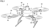
- Fig. 1 is a diagram showing a state that a drone is flying.
- Fig. 2 is a diagram showing a state of descent of the drone with a parachute having been ejected.
- a drone 1 includes a main body 2, four arms 3A, 3B, 3C, and 3D, four propulsive mechanisms 4A, 4B, 4C, and 4D, an ejection apparatus 5, a communication unit 6, and a support member 18.
- Each of propulsive mechanisms 4A, 4B, 4C, and 4D includes a propeller 41 (see Fig. 2 ) and a motor 42.
- any one arm of arms 3A, 3B, 3C, and 3D will also be referred to as an "arm 3" below.
- any one propulsive mechanism of propulsive mechanisms 4A, 4B, 4C, and 4D will also be referred to as a "propulsive mechanism 4.”
- Arm 3 is attached to main body 2.
- Arm 3 has a base end and a tip end.
- Arm 3 has the base end attached to main body 2.
- arm 3 extends from a side surface of main body 2.
- Propulsive mechanism 4 is attached to the tip end of arm 3.
- Motor 42 is attached to the tip end of arm 3.
- Propeller 41 is attached to a rotation shaft (not shown) of motor 42.
- Ejection apparatus 5 is attached to an upper surface (a top surface) of main body 2.
- a parachute 51 is accommodated in ejection apparatus 5.
- Ejection apparatus 5 ejects parachute 51 (see Fig. 2 ) when predetermined abnormality occurs in drone 1.
- Ejection apparatus 5 senses drop of drone 1 and instantaneously expands the parachute by activating a gas generator contained in ejection apparatus 5.
- An explosive gas generator pyrotechnic
- a non-explosive gas generator such as a canister type gas generator may be employed as the gas generator.
- Support member 18 extends upward from a portion of connection between arm 3 and main body 2 in the present example.
- Support member 18 is a hollow pipe.
- a wire for communication unit 6 passes.
- communication unit 6 is supported by support member 18 as being located above main body 2.
- drone 1 including four arms 3 and four propulsive mechanisms 4 is exemplified, the number of arms and the number of propulsive mechanisms are not limited as such.
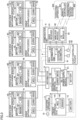
- Fig. 3 is a block diagram for illustrating a hardware configuration of drone 1.
- drone 1 can communicate with a terrestrial apparatus 900.
- Terrestrial apparatus 900 includes a remote controller 901 and a terrestrial control station 902.
- a main power path is shown with a solid line and a main signal path is shown with a dashed line.
- drone 1 includes drive apparatuses (electronic speed controllers (ESCs)) 7A, 7B, 7C, and 7D, a flight controller (an autopilot) 8, a battery 9, a power supply module 10, a disconnection apparatus (flight termination system (FTS)) 11, a distributor 12, a battery 13, a trigger apparatus (auto trigger system (ATS)) 14, and a sensor 15.
- ESCs electronic speed controllers
- FTS light termination system
- ATS auto trigger system
- sensor 15 any one drive apparatus of drive apparatuses 7A, 7B, 7C, and 7D will also be referred to as a "drive apparatus 7" below.
- propulsive mechanism 4 includes propeller 41 and motor 42.
- Motor 42 includes a magnet 421 and a coil 422.
- a type of motor 42 is not particularly limited.
- a brushless direct-current (DC) motor, a brushed DC motor, or an alternating-current (AC) motor can be employed as motor 42.
- Drive apparatus 7 includes a micro controller unit (MCU) 71 and a current driver 72.
- MCU micro controller unit
- Flight controller 8 includes an MCU 81, an inertial measurement unit (IMU) 82, and a pressure altimeter 83.
- MCU 81 includes an attitude estimator 811 and a determination unit 812 as functional blocks.
- MCU 81 is communicatively connected to inertial measurement unit 82 and pressure altimeter 83.
- Disconnection apparatus 11 includes a current switch 111.
- Trigger apparatus 14 includes an MCU 141 and a sensor 142.
- Sensor 142 detects an acceleration, an angular velocity, an attitude angle, and variation in altitude of drone 1.
- MCUs 71, 81, and 141 each specifically include a central processing unit (CPU), a memory such as a read only memory (ROM) and a random access memory (RAM), and an input/output (I/O) circuit which are not shown.
- CPU central processing unit
- ROM read only memory
- RAM random access memory
- I/O input/output circuit
- Communication unit 6 includes a global navigation satellite system (GNSS) receiver 61, a wireless module 62, and a long term evolution (LTE) module 63.
- GNSS global navigation satellite system
- LTE long term evolution
- Battery 9 is a storage battery (secondary battery). Battery 9 is connected to power supply module 10.
- Power supply module 10 supplies electric power from battery 9 to flight controller 8 and communication unit 6 through a power path R1. In the present example, power is fed to communication unit 6 through flight controller 8. Power supply module 10 supplies electric power from battery 9 to distributor 12 through a power path R2. Specifically, power supply module 10 supplies electric power from battery 9 to distributor 12 through disconnection apparatus 11. Power supply module 10 thus branches the power path from battery 9 into two power paths R1 and R2.
- a connector terminal of power supply module 10 and a connector terminal of distributor 12 are connected to each other through a wire.
- the connector terminal of power supply module 10 and the connector terminal of distributor 12 are preferably plated with gold in order to reduce heat generation due to contact resistance of the wire.
- Distributor 12 distributes supplied electric power to each of four drive apparatuses 7. Distributor 12 allows electric power supplied through power path R2 to be supplied to each of four drive apparatuses 7. Specifically, distributor 12 allows electric power to be supplied to current driver 72 of each of four drive apparatuses 7. Though not shown with the solid line, electric power is supplied also to each MCU 71. Current driver 72 and coil 422 of motor 42 are connected to each other through a wire.
- Drive apparatus 7 is communicatively connected to flight controller 8.
- Drive apparatus 7 drives corresponding propulsive mechanism 4 based on a command from flight controller 8.
- drive apparatus 7 adjusts propulsive force of corresponding propulsive mechanism 4 based on a command from flight controller 8.
- drive apparatus 7A adjusts propulsive force of corresponding propulsive mechanism 4A.
- drive apparatuses 7B, 7C, and 7D adjust propulsive force of respective propulsive mechanisms 4B, 4C, and 4D.
- Drive apparatus 7 thus functions as a control device that controls propulsive mechanism 4.
- MUC 71 receives a command from MUC 81 of flight controller 8.
- MCU 71 controls a current fed by current driver 72 to coil 422 of motor 42 based on the command.
- a rotation speed of motor 42 is controlled.
- a speed of rotation of propeller 41 can thus be controlled.
- GNSS receiver 61, wireless module 62, and LTE module 63 are communicatively connected to MCU 81 of flight controller 8.
- GNSS receiver 61, wireless module 62, and LTE module 63 receive supply of electric power from flight controller 8.
- GNSS receiver 61, wireless module 62, and LTE module 63 operate with electric power from battery 9.
- GNSS receiver 61 receives radio waves emitted from a plurality of positioning satellites (not shown) and obtains the current position of drone 1 based on received radio waves. GNSS receiver 61 periodically sends information indicating the current position to flight controller 8. Specifically, GNSS receiver 61 periodically sends information on a latitude and a longitude of drone 1 as position information to MCU 81.
- Wireless module 62 is a communication module for communication with remote controller 901. Communication between wireless module 62 and remote controller 901 is used in manual control of drone 1 within a range viewable by the operator. Therefore, this communication is real-time. A command from remote controller 901 is inputted to MCU 81 through wireless module 62.
- LTE module 63 is a communication module for communication with terrestrial control station 902 with a base station (not shown) being interposed. Communication between LTE module 63 and terrestrial control station 902 is used in flight of drone 1 over several kilometers by automatic control.
- MUC 81 transmits position information of drone 1 to terrestrial control station 902 through LTE module 63. Timing of transmission of the position information will be described later.
- Inertial measurement unit 82 periodically measures the angular velocity and the acceleration of drone 1 in a three-dimensional space.
- Pressure altimeter 83 periodically measures the altitude from the ground level and the sea level.
- Flight controller 8 controls flight of drone 1. Flight controller 8 realizes automatic control and manual control by a remote controller operation by the operator.
- flight controller 8 controls flight of drone 1 based on a predetermined flight route.
- MCU 81 of flight controller 8 implements autonomous flight of drone 1 based on the current position obtained by GNSS receiver 61, a result of detection by inertial measurement unit 82, and a result of detection (altitude) by pressure altimeter 83.
- flight controller 8 can transmit information on the current position of drone 1 through LTE module 63 which is the communication apparatus.
- attitude estimator 811 of MCU 81 estimates an attitude of drone 1 based on a result of detection by inertial measurement unit 82.
- Determination unit 812 of MCU 81 determines whether or not the estimated attitude is an abnormal attitude based on a predetermined reference.
- MCU 81 determines the estimated attitude as the abnormal attitude, it transmits a predetermined signal to trigger apparatus 14.
- Flight controller 8 transmits the information on the current position of drone 1 to terrestrial control station 902 through LTE module 63, based on occurrence of predetermined abnormality in drone 1.
- flight controller 8 may transmit the information on the current position of drone 1 to terrestrial control station 902 on condition that the drone has landed with the use of parachute 51.
- drone 1 can be determined as having landed.
- drone 1 can be determined as having landed based on the result of detection by pressure altimeter 83.
- Drone 1 can be determined as having landed also based on a result of detection by inertial measurement unit 82.
- Ejection apparatus 5 contains the parachute.
- ejection apparatus 5 ejects parachute 51.
- ejection apparatus 5 ejects parachute 51 in any of automatic control and manual control.
- disconnection apparatus 11 When the predetermined abnormality occurs, disconnection apparatus 11 cuts off supply of electric power from power supply module 10 to distributor 12 through power path R2. Specifically, disconnection apparatus 11 cuts off supply of electric power to distributor 12 by an operation of current switch 111. In the present example, disconnection apparatus 11 cuts of supply of electric power to distributor 12 in any of automatic control and manual control.
- Trigger apparatus 14 is fed with power from battery 13. Trigger apparatus 14 activates disconnection apparatus 11 and ejection apparatus 5 based on occurrence of predetermined abnormality in drone 1. Specifically, MCU 141 sends a prescribed signal (command) to ejection apparatus 5, so that ejection apparatus 5 ejects parachute 51 to the outside. As MCU 141 sends a prescribed signal (which will also be referred to as a "current break command signal” below) to disconnection apparatus 11, current switch 111 of disconnection apparatus 11 is activated. As a result of the activation, supply of electric power from power supply module 10 to distributor 12 through power path R2 is cut off. Drone 1 is thus forced to stop autonomous flight.
- a prescribed signal which will also be referred to as a "current break command signal” below
- the current break command signal above is desirably resistant to variation in voltage caused by electromagnetic noise.
- the current break command signal is preferably a signal having as a variable, a time period for which the High level of a voltage is held.
- Examples of the predetermined abnormality include the estimated attitude being an abnormal attitude and deviation from a scheduled flight route. Based on determination by MCU 81 of flight controller 8 that the attitude of drone 1 is abnormal or determination by MUC 81 as deviation from the flight route, MCU 141 of trigger apparatus 14 activates disconnection apparatus 11 and ejection apparatus 5.
- trigger apparatus 14 may determine whether or not predetermined abnormality has occurred based on a result of sensing by sensor 142.
- a type of abnormality is not particularly limited so long as it is set in advance.
- trigger apparatus 14 when a prescribed condition is satisfied after trigger apparatus 14 causes disconnection apparatus 11 to cut off supply of electric power to distributor 12 through power path R2, trigger apparatus 14 causes ejection apparatus 5 to eject parachute 51. Specifically, when a prescribed time period (for example, one second) has elapsed after trigger apparatus 14 caused disconnection apparatus 11 to cut off supply of electric power to distributor 12 through power path R2, trigger apparatus 14 causes ejection apparatus 5 to eject parachute 51.
- a prescribed time period for example, one second
- the prescribed time period is preferably within 1.5 second.
- the prescribed time period is preferably set to a time period longer than a time period in which rotation of propeller 41 stops.
- Sensor 15 detects whether or not ejection apparatus 5 has been activated. Sensor 15 is communicatively connected to flight controller 8. When the predetermined abnormality occurs, flight controller 8 transmits through LTE module 63 to terrestrial control station 902, the fact of forced stop of the flight and the result of detection by sensor 15. Flight controller 8 may transmit information indicating the type of abnormality to terrestrial control station 902.
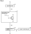
- Fig. 4 is a diagram for illustrating a specific example of disconnection apparatus 11. As shown in Fig. 4 , disconnection apparatus 11 includes a transistor 111A that functions as current switch 111.
- Transistor 111A is provided between power supply module 10 and distributor 12 and allows a flow of a current from power supply module 10 to distributor 12 through power path R2 while it is on.
- transistor 111A is a bipolar transistor.
- transistor 111A is an npn-type transistor.
- disconnection apparatus 11 turns off transistor 111A. As disconnection apparatus 11 switches a state of transistor 111A from on to off, it cuts off supply of electric power from power supply module 10 to distributor 12 through power path R2.
- Transistor 111A is not limited to the npn-type bipolar transistor.
- Transistor 111A may be a pnp-type bipolar transistor.
- transistor 111A may be a field effect transistor (unipolar transistor).
- transistor 111A may be a junction field effect transistor (FET) or a MOS field effect transistor.
- transistor 111A may be an insulated gate bipolar transistor (IGBT).
- Transistor 111A generates heat as a result of energization.
- disconnection apparatus 11 preferably includes a heat sink member that radiates heat of transistor 111A.
- Disconnection apparatus 11 may include a substrate of an aluminum material for heat radiation or an electric fan for cooling instead of or together with the heat sink member.
- disconnection apparatus 11 When transistor 111A is switched from on to off, a surge voltage is generated.
- disconnection apparatus 11 preferably includes a snubber circuit.
- the snubber circuit includes at least one of a resistor and a capacitor.
- Fig. 5 is a flowchart for illustrating a flow of processing performed in drone 1.
- step S1 drone 1 starts flying.
- step S2 drone 1 determines whether or not the predetermined abnormality described above has occurred therein.
- step S3 drone 1 determines whether or not it has arrived at a destination.
- drone 1 determines whether or not it has arrived at the destination (YES in step S3), it quits a series of processing.
- drone 1 has determined that it has not arrived at the destination (NO in step S3), it has the process return to step S2.
- drone 1 determines that abnormality has occurred (YES in step S2), it activates disconnection apparatus 11 in step S4. In step S5, drone 1 determines whether or not a prescribed time period (for example, one second) has elapsed since activation of disconnection apparatus 11.
- a prescribed time period for example, one second
- step S6 When drone 1 determines that the prescribed time period has elapsed (YES in step S5), in step S6, it activates ejection apparatus 5. In other words, drone 1 ejects parachute 51. When drone 1 determines that the prescribed time period has not elapsed (NO in step S5), it has the process return to step S5.
- step S7 drone 1 periodically transmits the position information indicating the current position thereof to terrestrial apparatus 900.
- a base station apparatus (not shown) provided around drone 1 receives the position information of drone 1, so that terrestrial control station 902 can obtain the position information.
- Drone 1 further includes ejection apparatus 5 that includes parachute 51 ( Fig. 2 ) and ejects parachute 51 when the predetermined abnormality occurs. Therefore, even when all propulsive mechanisms 4 are deactivated by disconnection of power path R2 based on occurrence of the predetermined abnormality, crash of drone 1 can be prevented according to the configuration above.
- drone 1 even when the abnormality above occurs, flight controller 8, GNSS receiver 61, and LTE module 62 can keep operating, so that the operator can accurately know the position of descent of drone 1. The drone is thus readily collected.
- drone 1 when the abnormality above occurs, the plurality of propulsive mechanisms 4 can be deactivated. Therefore, drone 1 can slowly descend with the use of parachute 51. In addition, flight of drone 1 with the use of the plurality of propulsive mechanisms 4 can be stopped.
- drone 1 on the other hand, even when drive apparatus 7 fails, supply of electric power to all drive apparatuses 7 is stopped as a result of disconnection of power path R2, and hence drive by all drive apparatuses 7 can be stopped. Therefore, according to drone 1, all propulsive mechanisms 4 can be deactivated.
- a configuration in which a power supply circuit between the drive apparatus and the propulsive mechanism is disconnected when abnormality occurs will be described as a fourth comparative example.
- disconnection apparatuses as many as the propulsive mechanisms (that is, the drive apparatuses) are required. Unless all disconnection apparatuses operate, at least one propulsive mechanism keeps operating.
- drone 1 According to drone 1 according to the present embodiment, on the other hand, disconnection of a single power path R2 suffices, and hence a single disconnection apparatus 11 suffices. Therefore, according to drone 1, cost can be lower than in the fourth comparative example.
- a probability of failure of one disconnection apparatus 11 in the present embodiment over a certain period is compared with a probability of failure of any one of the plurality of disconnection apparatuses shown in the fourth comparative example. Then, in correspondence with a larger number of disconnection apparatuses, the latter probability can be concluded as being higher. Therefore, according to drone 1, the probability of occurrence of such a situation that any propulsive mechanism keeps operating on the occurrence of abnormality can be lower than in the fourth comparative example where a plurality of disconnection apparatuses are required.
- Drone 1 includes trigger apparatus 14 that activates disconnection apparatus 11 and ejection apparatus 5 when the predetermined abnormality occurs.
- Trigger apparatus 14 causes ejection apparatus 5 to eject parachute 51 when a prescribed condition is satisfied after it caused disconnection apparatus 11 to cut off supply of electric power to distributor 12 through power path R2.
- Flight controller 8 transmits information on the current position of drone 1 to terrestrial apparatus 900 through LTE module 62 based on occurrence of the predetermined abnormality. According to such a configuration, when abnormality occurs in drone 1, terrestrial apparatus 900 can know the current position of drone 1.
- Drone 1 includes sensor 15 that detects whether or not ejection apparatus 5 has been activated.
- flight controller 8 notifies terrestrial apparatus 900 of a result of detection by sensor 15, through LTE module 62.
- terrestrial apparatus 900 can know whether or not drone 1 has expanded parachute 51.
- Disconnection apparatus 11 includes transistor 111A ( Fig. 4 ) provided between power supply module 10 and distributor 12, transistor 111A allowing a flow of the current from power supply module 10 to distributor 12 through power path R2 while it is on.
- transistor 111A allowing a flow of the current from power supply module 10 to distributor 12 through power path R2 while it is on.
- drone 1 turns off transistor 111A. According to such a configuration, supply of electric power from power supply module 10 to distributor 12 can be stopped. Therefore, drive of all propulsive mechanisms 4 can be stopped.
- Each propulsive mechanism 4 includes propeller 41 and motor 42 that rotates propeller 41.
- Each drive apparatus 7 drives motor 42.
- drone 1 includes a disconnection apparatus 11A instead of disconnection apparatus 11.
- Disconnection apparatus 11A includes an igniter 150, a cut-off chamber 160 containing an internal space, and a rupture plate 163 that is damaged and cleaved as a result of application of heat and a pressure produced by activation of igniter 150 and disconnects power path R2.
- trigger apparatus 14 transmits a prescribed signal (command) to disconnection apparatus 11A so that igniter 150 is driven.
- Igniter 150 ignites a flame, and includes an ignition portion 151 containing an ignition agent (not shown) that ignites a flame by being fired and burnt at the time of activation and a resistor (not shown) for ignition of the ignition agent and a pair of terminal pins 152 connected to ignition portion 151.
- a through hole 161 is provided in a peripheral wall of cut-off chamber 160 and a through hole 162 is provided in another portion of the peripheral wall.
- Power path R2 lies like a bridge between through holes 161 and 162.
- Power path R2 is implemented by a bus bar.
- Power path R2 is formed, for example, from a metal plate or a metal wire.
- Power path R2 has one end connected to power supply module 10 and has the other end connected to distributor 12.
- rupture plate 163 When abnormality is sensed in drone 1 and when the prescribed amount of current is supplied to the pair of terminal pins 152 of igniter 150 in response to the command from trigger apparatus 14, rupture plate 163 is damaged by heat and the pressure produced by activation of ignition portion 151 as shown in Fig. 7 . In this case, rupture plate 163 is damaged in such a manner that a central portion thereof is cleaved and bent toward power path R2. Power path R2 (specifically, the bus bar) is cut off by damaged rupture plate 163.
- an actuator may cut the bus bar.
- the bus bar may be cut by movement of a piston by a gas pressure.
- a fuse may be provided on an electric circuit and a current greater than a rated current may be fed to the fuse to blow the fuse. According to such a configuration as well, drive of all propulsive mechanisms 4 can be stopped similarly to the above.
- Fig. 8 is a diagram for illustrating a second modification of disconnection apparatus 11.
- drone 1 includes a disconnection apparatus 11B instead of disconnection apparatus 11.
- Disconnection apparatus 11B includes a relay switch 111B.
- Relay switch 111B includes a coil 171, a moving contact 172, and a fixed contact 173.
- relay switch 111B a current is fed to coil 171 so that moving contact 172 comes in contact with fixed contact 173. In other words, relay switch 111B is turned on. When feed of the current to coil 171 is stopped, moving contact 172 moves away from fixed contact 173 and relay switch 111B is turned off.
- a contactor an electromagnetic contactor
- Battery 9 is preferably attachable and removable. When battery 9 is running low, battery 9 is removed and a completely charged battery is attached, so that drone 1 can fly without waiting for charging. Drone 1 can thus efficiently operate.
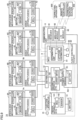
- Fig. 9 is a block diagram for illustrating a hardware configuration of a drone 1A which is a modification of drone 1.
- communication unit 6 receives supply of electric power by battery 9 through a power path R3 from power supply module 10, instead of reception of supply of electric power by battery 9 from flight controller 8.
- power supply module 10 supplies electric power from battery 9 to flight controller 8 through power path R1, to distributor 12 through power path R2, and to GNSS receiver 61, wireless module 62, and LTE module 63 through power path R3.
- GNSS receiver 61, wireless module 62, and LTE module 63 through power path R3.
- Drone 1 and drone 1A may further include another not-shown battery, and another battery may be configured to supply electric power to communication unit 6 (specifically, GNSS receiver 61, wireless module 62, and LTE module 63).
- An aerial vehicle in which the battery includes a first battery (corresponding to battery 9) and a second battery (corresponding to another battery), power supply module 10 supplies electric power from the first battery to the flight controller through a first power path and to the distributor through a second power path and supplies electric power from the second battery to the communication apparatus and the receiver through a third power path.
- the battery includes a first battery (corresponding to battery 9) and a second battery (corresponding to another battery)
- power supply module 10 supplies electric power from the first battery to the flight controller through a first power path and to the distributor through a second power path and supplies electric power from the second battery to the communication apparatus and the receiver through a third power path.
Landscapes
- Engineering & Computer Science (AREA)
- Aviation & Aerospace Engineering (AREA)
- Chemical & Material Sciences (AREA)
- Combustion & Propulsion (AREA)
- Mechanical Engineering (AREA)
- Remote Sensing (AREA)
- Control Of Position, Course, Altitude, Or Attitude Of Moving Bodies (AREA)
- Charge And Discharge Circuits For Batteries Or The Like (AREA)
Abstract
Description
- The present disclosure relates to an aerial vehicle and a method of controlling an aerial vehicle.
- Various manned aircrafts and various unmanned aircrafts have conventionally been known as aerial vehicles.
- For example,
US Patent Publication No. 2017/0106986A1 (PTL 1) discloses an unmanned aircraft provided with a parachute. When the unmanned aircraft inPTL 1 senses a crash or the like, it expands the parachute and stops power feed to a motor that rotates a propeller. Specifically, in the unmanned aircraft inPTL 1, a power supply and the motor that rotates the propeller are directly connected to each other through a wire. When the unmanned aircraft inPTL 1 senses the crash or the like, it physically disconnects the power supply and the motor from each other. Power feed to the motor is thus stopped. -
WO2019/216204A1 (PTL 2) discloses a current breaker included in an unmanned aircraft provided with a parachute. The current breaker cuts off supply of the current to an electric device of the unmanned aircraft. Occurrence of failure in expansion of the parachute at the time of (during) a crash of the unmanned aircraft is thus prevented. Furthermore, occurrence of accidental contact between an operating propeller and a human after the crash is prevented. -
WO2017/030034A1 (PTL 3) discloses an unmanned aircraft in which a battery is chargeable by a power generator during flight for achieving a longer flight distance. When the unmanned aircraft senses a crash thereof, it stops charging from the power generator to the battery. Damage caused by an accident following the crash of the unmanned aircraft is thus prevented from spreading. -
- PTL 1:
US Patent Publication No. 2017/0106986A1 - PTL 2:
WO2019/216204A1 - PTL 3:
WO2017/030034A1 - The unmanned aircraft in
PTL 1 includes an electronic speed controller (ESC) that drives the motor described above. The electronic speed controller is specifically a motor driver (amplifier) that controls the number of rotations of the motor by feed of a current to the motor. The electronic speed controller controls a flying speed of the unmanned aircraft. Therefore, even when the power supply and the motor are disconnected from each other as above, the current flows from the power supply to the motor through the electronic speed controller. Therefore, the unmanned aircraft inPTL 1 is actually unable to stop rotation of the propeller by disconnection as above. - The unmanned aircraft including the current breaker in
PTL 2 causes the current breaker to cut off supply of the current to the electric device thereof at the time of crash. Therefore, at the time of crash of the unmanned aircraft (descent with the use of the parachute), the unmanned aircraft is unable to calculate the current position and to communicate with an external device on the ground. Therefore, the external device on the ground is unable to specify the current position of the unmanned aircraft. - Even when the unmanned aircraft in
PTL 3 senses the crash thereof, power is kept supplied from the battery to the motor that rotates the propeller. In other words, a propulsive mechanism (the propeller and the motor) of the unmanned aircraft keeps operating. - The present disclosure was made in view of the problems above, and an object thereof is to provide an aerial vehicle capable of deactivating all propulsive mechanisms by disconnection of a single power path and capable of transmitting information on a current position to an external device also after disconnection of the power path, and a method of controlling an aerial vehicle.
- According to one aspect of the present disclosure, an aerial vehicle includes a battery, a plurality of propulsive mechanisms, a communication apparatus for wireless communication with an external device, a receiver that obtains a current position of the aerial vehicle by receiving radio waves emitted from a plurality of positioning satellites, a flight controller that controls flight of the aerial vehicle and can transmit information on the current position through the communication apparatus, a plurality of drive apparatuses each communicatively connected to the flight controller, the plurality of drive apparatuses driving respective different ones of the plurality of propulsive mechanisms, a distributor that distributes supplied electric power to each of the plurality of drive apparatuses, a power supply module that supplies electric power from the battery to the communication apparatus, the receiver, and the flight controller through a first power path and supplies electric power to the distributor through a second power path, and a disconnection apparatus that cuts off supply of electric power from the power supply module to the distributor through the second power path when predetermined abnormality occurs in the aerial vehicle.
- According to another aspect of the present disclosure, an aerial vehicle supplies electric power from a contained battery through a first power path, to a flight controller that controls flight of the aerial vehicle, a communication apparatus for wireless communication with an external device, and a receiver that calculates a current position of the aerial vehicle, and supplies electric power through a second power path, to a distributor that distributes electric power to each of a plurality of drive apparatuses. The drive apparatuses drive respective different ones of a plurality of propulsive mechanisms based on a command from the flight controller. A method of controlling the aerial vehicle includes cutting off supply of electric power to the distributor through the second power path when predetermined abnormality occurs in the aerial vehicle and transmitting to the external device, information on the current position through the communication apparatus when the predetermined abnormality occurs.
- According to the present disclosure, when predetermined abnormality occurs in the aerial vehicle, all propulsive mechanisms can be deactivated by disconnection of a single power path, and information on the current position can be transmitted to an external device also after the power path is disconnected.
-
-
Fig. 1 is a diagram showing a state that a drone is flying. -
Fig. 2 is a diagram showing a state of descent of the drone with a parachute having been ejected. -
Fig. 3 is a block diagram for illustrating a hardware configuration of the drone. -
Fig. 4 is a diagram for illustrating a specific example of a disconnection apparatus. -
Fig. 5 is a flowchart for illustrating a flow of processing performed in the drone. -
Fig. 6 is a diagram showing a state before disconnection of a power path in a first modification of the disconnection apparatus. -
Fig. 7 is a diagram showing a state after disconnection of the power path in the first modification of the disconnection apparatus. -
Fig. 8 is a diagram for illustrating a second modification of the disconnection apparatus. -
Fig. 9 is a block diagram for illustrating a hardware configuration of another drone. - An embodiment according to the present invention will be described below with reference to the drawings. In the description below, the same components and constituent elements have the same reference characters allotted and their labels and functions are also the same. Therefore, detailed description thereof will not be repeated.
- An unmanned aircraft will be described below by way of example of an aerial vehicle. Specifically, a drone as the unmanned aircraft will be described by way of example. More specifically, a drone with rotary wings will be described by way of example. The present disclosure is also applicable to various manned aircrafts (other examples of the aerial vehicle) such as a "flying car."
- A drone according to the present embodiment is adapted to automatic control and manual control by a remote controller operation by an operator.
Fig. 1 is a diagram showing a state that a drone is flying.Fig. 2 is a diagram showing a state of descent of the drone with a parachute having been ejected. - As shown in
Figs. 1 and2 , adrone 1 includes amain body 2, fourarms propulsive mechanisms ejection apparatus 5, acommunication unit 6, and asupport member 18. Each ofpropulsive mechanisms Fig. 2 ) and amotor 42. - For the sake of convenience of description, any one arm of
arms arm 3" below. Similarly, any one propulsive mechanism ofpropulsive mechanisms propulsive mechanism 4." -
Arm 3 is attached tomain body 2.Arm 3 has a base end and a tip end.Arm 3 has the base end attached tomain body 2. In the present example,arm 3 extends from a side surface ofmain body 2. -
Propulsive mechanism 4 is attached to the tip end ofarm 3.Motor 42 is attached to the tip end ofarm 3.Propeller 41 is attached to a rotation shaft (not shown) ofmotor 42. -
Ejection apparatus 5 is attached to an upper surface (a top surface) ofmain body 2. Aparachute 51 is accommodated inejection apparatus 5.Ejection apparatus 5 ejects parachute 51 (seeFig. 2 ) when predetermined abnormality occurs indrone 1.Ejection apparatus 5 senses drop ofdrone 1 and instantaneously expands the parachute by activating a gas generator contained inejection apparatus 5. An explosive gas generator (pyrotechnic) or a non-explosive gas generator such as a canister type gas generator may be employed as the gas generator. -
Support member 18 extends upward from a portion of connection betweenarm 3 andmain body 2 in the present example.Support member 18 is a hollow pipe. In the inside ofsupport member 18, a wire forcommunication unit 6 passes. In the present example,communication unit 6 is supported bysupport member 18 as being located abovemain body 2. - Though
drone 1 including fourarms 3 and fourpropulsive mechanisms 4 is exemplified, the number of arms and the number of propulsive mechanisms are not limited as such. -
Fig. 3 is a block diagram for illustrating a hardware configuration ofdrone 1. As shown inFig. 3 ,drone 1 can communicate with aterrestrial apparatus 900.Terrestrial apparatus 900 includes aremote controller 901 and aterrestrial control station 902. InFig. 3 , a main power path is shown with a solid line and a main signal path is shown with a dashed line. - In addition to
propulsive mechanisms ejection apparatus 5, andcommunication unit 6 described above,drone 1 includes drive apparatuses (electronic speed controllers (ESCs)) 7A, 7B, 7C, and 7D, a flight controller (an autopilot) 8, abattery 9, apower supply module 10, a disconnection apparatus (flight termination system (FTS)) 11, adistributor 12, abattery 13, a trigger apparatus (auto trigger system (ATS)) 14, and asensor 15. For the sake of convenience of description, any one drive apparatus ofdrive apparatuses drive apparatus 7" below. - As described above,
propulsive mechanism 4 includespropeller 41 andmotor 42.Motor 42 includes amagnet 421 and acoil 422. A type ofmotor 42 is not particularly limited. For example, a brushless direct-current (DC) motor, a brushed DC motor, or an alternating-current (AC) motor can be employed asmotor 42.Drive apparatus 7 includes a micro controller unit (MCU) 71 and acurrent driver 72. -
Flight controller 8 includes anMCU 81, an inertial measurement unit (IMU) 82, and apressure altimeter 83.MCU 81 includes anattitude estimator 811 and adetermination unit 812 as functional blocks.MCU 81 is communicatively connected toinertial measurement unit 82 andpressure altimeter 83. -
Disconnection apparatus 11 includes acurrent switch 111.Trigger apparatus 14 includes anMCU 141 and asensor 142.Sensor 142 detects an acceleration, an angular velocity, an attitude angle, and variation in altitude ofdrone 1. -
MCUs drone 1 is stored in the memory ofMUC 81. -
Communication unit 6 includes a global navigation satellite system (GNSS)receiver 61, awireless module 62, and a long term evolution (LTE)module 63. -
Battery 9 is a storage battery (secondary battery).Battery 9 is connected topower supply module 10. -
Power supply module 10 supplies electric power frombattery 9 toflight controller 8 andcommunication unit 6 through a power path R1. In the present example, power is fed tocommunication unit 6 throughflight controller 8.Power supply module 10 supplies electric power frombattery 9 todistributor 12 through a power path R2. Specifically,power supply module 10 supplies electric power frombattery 9 todistributor 12 throughdisconnection apparatus 11.Power supply module 10 thus branches the power path frombattery 9 into two power paths R1 and R2. - In power path R2, a connector terminal of
power supply module 10 and a connector terminal ofdistributor 12 are connected to each other through a wire. The connector terminal ofpower supply module 10 and the connector terminal ofdistributor 12 are preferably plated with gold in order to reduce heat generation due to contact resistance of the wire. -
Distributor 12 distributes supplied electric power to each of fourdrive apparatuses 7.Distributor 12 allows electric power supplied through power path R2 to be supplied to each of fourdrive apparatuses 7. Specifically,distributor 12 allows electric power to be supplied tocurrent driver 72 of each of fourdrive apparatuses 7. Though not shown with the solid line, electric power is supplied also to eachMCU 71.Current driver 72 andcoil 422 ofmotor 42 are connected to each other through a wire. -
Drive apparatus 7 is communicatively connected toflight controller 8.Drive apparatus 7 drives correspondingpropulsive mechanism 4 based on a command fromflight controller 8. Specifically,drive apparatus 7 adjusts propulsive force of correspondingpropulsive mechanism 4 based on a command fromflight controller 8. Specifically,drive apparatus 7A adjusts propulsive force of correspondingpropulsive mechanism 4A. Similarly, driveapparatuses propulsive mechanisms Drive apparatus 7 thus functions as a control device that controlspropulsive mechanism 4. - Specifically,
MUC 71 receives a command fromMUC 81 offlight controller 8.MCU 71 controls a current fed bycurrent driver 72 tocoil 422 ofmotor 42 based on the command. By such control of the current to be fed tocoil 422, a rotation speed ofmotor 42 is controlled. A speed of rotation ofpropeller 41 can thus be controlled. -
GNSS receiver 61,wireless module 62, andLTE module 63 are communicatively connected to MCU 81 offlight controller 8.GNSS receiver 61,wireless module 62, andLTE module 63 receive supply of electric power fromflight controller 8.GNSS receiver 61,wireless module 62, andLTE module 63 operate with electric power frombattery 9. -
GNSS receiver 61 receives radio waves emitted from a plurality of positioning satellites (not shown) and obtains the current position ofdrone 1 based on received radio waves.GNSS receiver 61 periodically sends information indicating the current position toflight controller 8. Specifically,GNSS receiver 61 periodically sends information on a latitude and a longitude ofdrone 1 as position information toMCU 81. -
Wireless module 62 is a communication module for communication withremote controller 901. Communication betweenwireless module 62 andremote controller 901 is used in manual control ofdrone 1 within a range viewable by the operator. Therefore, this communication is real-time. A command fromremote controller 901 is inputted to MCU 81 throughwireless module 62. -
LTE module 63 is a communication module for communication withterrestrial control station 902 with a base station (not shown) being interposed. Communication betweenLTE module 63 andterrestrial control station 902 is used in flight ofdrone 1 over several kilometers by automatic control. In the present example,MUC 81 transmits position information ofdrone 1 toterrestrial control station 902 throughLTE module 63. Timing of transmission of the position information will be described later. -
Inertial measurement unit 82 periodically measures the angular velocity and the acceleration ofdrone 1 in a three-dimensional space.Pressure altimeter 83 periodically measures the altitude from the ground level and the sea level. -
Flight controller 8 controls flight ofdrone 1.Flight controller 8 realizes automatic control and manual control by a remote controller operation by the operator. - In automatic control,
flight controller 8 controls flight ofdrone 1 based on a predetermined flight route. Specifically,MCU 81 offlight controller 8 implements autonomous flight ofdrone 1 based on the current position obtained byGNSS receiver 61, a result of detection byinertial measurement unit 82, and a result of detection (altitude) bypressure altimeter 83. As described above,flight controller 8 can transmit information on the current position ofdrone 1 throughLTE module 63 which is the communication apparatus. - More specifically,
attitude estimator 811 ofMCU 81 estimates an attitude ofdrone 1 based on a result of detection byinertial measurement unit 82.Determination unit 812 ofMCU 81 determines whether or not the estimated attitude is an abnormal attitude based on a predetermined reference. WhenMCU 81 determines the estimated attitude as the abnormal attitude, it transmits a predetermined signal to triggerapparatus 14. -
Flight controller 8 transmits the information on the current position ofdrone 1 toterrestrial control station 902 throughLTE module 63, based on occurrence of predetermined abnormality indrone 1. - Without being limited as such,
flight controller 8 may transmit the information on the current position ofdrone 1 toterrestrial control station 902 on condition that the drone has landed with the use ofparachute 51. When the current position does not change for a certain time period or longer,drone 1 can be determined as having landed. Alternatively,drone 1 can be determined as having landed based on the result of detection bypressure altimeter 83.Drone 1 can be determined as having landed also based on a result of detection byinertial measurement unit 82. -
Ejection apparatus 5 contains the parachute. When the predetermined abnormality occurs indrone 1,ejection apparatus 5 ejectsparachute 51. In the present example,ejection apparatus 5 ejectsparachute 51 in any of automatic control and manual control. - When the predetermined abnormality occurs,
disconnection apparatus 11 cuts off supply of electric power frompower supply module 10 todistributor 12 through power path R2. Specifically,disconnection apparatus 11 cuts off supply of electric power todistributor 12 by an operation ofcurrent switch 111. In the present example,disconnection apparatus 11 cuts of supply of electric power todistributor 12 in any of automatic control and manual control. -
Trigger apparatus 14 is fed with power frombattery 13.Trigger apparatus 14 activatesdisconnection apparatus 11 andejection apparatus 5 based on occurrence of predetermined abnormality indrone 1. Specifically,MCU 141 sends a prescribed signal (command) toejection apparatus 5, so thatejection apparatus 5 ejectsparachute 51 to the outside. AsMCU 141 sends a prescribed signal (which will also be referred to as a "current break command signal" below) todisconnection apparatus 11,current switch 111 ofdisconnection apparatus 11 is activated. As a result of the activation, supply of electric power frompower supply module 10 todistributor 12 through power path R2 is cut off.Drone 1 is thus forced to stop autonomous flight. - The current break command signal above is desirably resistant to variation in voltage caused by electromagnetic noise. For example, the current break command signal is preferably a signal having as a variable, a time period for which the High level of a voltage is held.
- Examples of the predetermined abnormality include the estimated attitude being an abnormal attitude and deviation from a scheduled flight route. Based on determination by
MCU 81 offlight controller 8 that the attitude ofdrone 1 is abnormal or determination byMUC 81 as deviation from the flight route,MCU 141 oftrigger apparatus 14 activatesdisconnection apparatus 11 andejection apparatus 5. - Without being limited as such,
trigger apparatus 14 may determine whether or not predetermined abnormality has occurred based on a result of sensing bysensor 142. A type of abnormality is not particularly limited so long as it is set in advance. - In the present example, when a prescribed condition is satisfied after
trigger apparatus 14 causesdisconnection apparatus 11 to cut off supply of electric power todistributor 12 through power path R2,trigger apparatus 14 causesejection apparatus 5 to ejectparachute 51. Specifically, when a prescribed time period (for example, one second) has elapsed aftertrigger apparatus 14 causeddisconnection apparatus 11 to cut off supply of electric power todistributor 12 through power path R2,trigger apparatus 14 causesejection apparatus 5 to ejectparachute 51. - The prescribed time period is preferably within 1.5 second. The prescribed time period is preferably set to a time period longer than a time period in which rotation of
propeller 41 stops. -
Sensor 15 detects whether or notejection apparatus 5 has been activated.Sensor 15 is communicatively connected toflight controller 8. When the predetermined abnormality occurs,flight controller 8 transmits throughLTE module 63 toterrestrial control station 902, the fact of forced stop of the flight and the result of detection bysensor 15.Flight controller 8 may transmit information indicating the type of abnormality toterrestrial control station 902. -
Fig. 4 is a diagram for illustrating a specific example ofdisconnection apparatus 11. As shown inFig. 4 ,disconnection apparatus 11 includes atransistor 111A that functions ascurrent switch 111. -
Transistor 111A is provided betweenpower supply module 10 anddistributor 12 and allows a flow of a current frompower supply module 10 todistributor 12 through power path R2 while it is on. In the present example,transistor 111A is a bipolar transistor. Specifically,transistor 111A is an npn-type transistor. - When the predetermined abnormality described above occurs,
disconnection apparatus 11 turns offtransistor 111A. Asdisconnection apparatus 11 switches a state oftransistor 111A from on to off, it cuts off supply of electric power frompower supply module 10 todistributor 12 through power path R2. -
Transistor 111A is not limited to the npn-type bipolar transistor.Transistor 111A may be a pnp-type bipolar transistor. Alternatively,transistor 111A may be a field effect transistor (unipolar transistor). In this case,transistor 111A may be a junction field effect transistor (FET) or a MOS field effect transistor. Furthermore,transistor 111A may be an insulated gate bipolar transistor (IGBT). -
Transistor 111A generates heat as a result of energization. In order to prevent a temperature oftransistor 111A from exceeding a rated temperature,disconnection apparatus 11 preferably includes a heat sink member that radiates heat oftransistor 111A.Disconnection apparatus 11 may include a substrate of an aluminum material for heat radiation or an electric fan for cooling instead of or together with the heat sink member. - When
transistor 111A is switched from on to off, a surge voltage is generated. In order to prevent break oftransistor 111A by the surge voltage,disconnection apparatus 11 preferably includes a snubber circuit. The snubber circuit includes at least one of a resistor and a capacitor. -
Fig. 5 is a flowchart for illustrating a flow of processing performed indrone 1. As shown inFig. 5 , in step S1,drone 1 starts flying. In step S2,drone 1 determines whether or not the predetermined abnormality described above has occurred therein. Whendrone 1 determines that abnormality has not occurred (NO in step S2), the process proceeds to step S3. In step S3,drone 1 determines whether or not it has arrived at a destination. Whendrone 1 has determined that it has arrived at the destination (YES in step S3), it quits a series of processing. Whendrone 1 has determined that it has not arrived at the destination (NO in step S3), it has the process return to step S2. - When
drone 1 determines that abnormality has occurred (YES in step S2), it activatesdisconnection apparatus 11 in step S4. In step S5,drone 1 determines whether or not a prescribed time period (for example, one second) has elapsed since activation ofdisconnection apparatus 11. - When
drone 1 determines that the prescribed time period has elapsed (YES in step S5), in step S6, it activatesejection apparatus 5. In other words,drone 1 ejectsparachute 51. Whendrone 1 determines that the prescribed time period has not elapsed (NO in step S5), it has the process return to step S5. - In step S7,
drone 1 periodically transmits the position information indicating the current position thereof toterrestrial apparatus 900. Specifically, a base station apparatus (not shown) provided arounddrone 1 receives the position information ofdrone 1, so thatterrestrial control station 902 can obtain the position information. -
- (1) Referring to
Figs. 2 and3 , as described above, drone 1 which is the unmanned aircraft includes (a) battery 9, (b) a plurality of propulsive mechanisms 4 (4A to 4B), (c) LTE module (communication apparatus) 62 for wireless communication with terrestrial apparatus 900 (specifically, terrestrial control station 902) which is the external device, (d) GNSS receiver 61 that obtains the current position of drone 1 by receiving radio waves emitted from a plurality of positioning satellites, (e) flight controller 8 that controls flight of drone 1 and can transmit information on the current position through LTE module 62, (f) a plurality of drive apparatuses 7 (7A to 7D) each communicatively connected to flight controller 8 and driving respective different ones of the plurality of propulsive mechanisms 4, (g) distributor 12 that distributes supplied electric power to each of the plurality of drive apparatuses 7, (h) power supply module 10 that supplies electric power from battery 9 to LTE module 62, GNN receiver 61, and flight controller 8 through power path R1 and supplies electric power to distributor 12 through power path R2, and (i) disconnection apparatus 11 that cuts off supply of electric power from power supply module 10 to distributor 12 through power path R2 when predetermined abnormality occurs in drone 1. - According to the configuration above, when predetermined abnormality occurs, power path R2 is disconnected. Therefore, supply of electric power from
battery 9 throughdistributor 12 to all driveapparatuses 7 is cut off. Furthermore, as a result of cut-off of supply of electric power to driveapparatuses 7, drive of allpropulsive mechanisms 4 is stopped. By thus disconnecting a single power path R2, allpropulsive mechanisms 4 can be deactivated. - Even when power path R2 is disconnected, supply of electric power through power path R1 to
LTE module 62,GNN receiver 61, andflight controller 8 continues. Therefore, according todrone 1, the information on the current position can be transmitted toterrestrial apparatus 900 also after power path R2 is disconnected. -
Drone 1 further includesejection apparatus 5 that includes parachute 51 (Fig. 2 ) and ejectsparachute 51 when the predetermined abnormality occurs. Therefore, even when allpropulsive mechanisms 4 are deactivated by disconnection of power path R2 based on occurrence of the predetermined abnormality, crash ofdrone 1 can be prevented according to the configuration above. - Advantages of
drone 1 will further be described below with reference to four comparative examples. - An example in which supply of electric power from the battery to the drone as a whole is stopped when the abnormality above occurs will be described as a first comparative example. In this case, at least the flight controller, the GNSS receiver, and a communication device for communication with a terrestrial facility do not operate. Therefore, in such a case, an operator on the ground is unable to obtain the latitude and the longitude of the drone. Therefore, the operator is unable to determine a position of descent of the drone. Accordingly, the operator is unable to collect the drone.
- In contrast, according to
drone 1 according to the present embodiment, even when the abnormality above occurs,flight controller 8,GNSS receiver 61, andLTE module 62 can keep operating, so that the operator can accurately know the position of descent ofdrone 1. The drone is thus readily collected. - An example in which the flight controller performs a propulsive mechanism deactivation function of the flight controller when abnormality occurs will be described as a second comparative example. In this case, when the flight controller itself fails (abnormality occurs therein), the plurality of propulsive mechanisms cannot be deactivated. Therefore, the plurality of propulsive mechanisms keep operating with the parachute having been expanded. In this case, the propulsive mechanisms may interfere with the parachute. For example, cords (lines) of the parachute may be entangled with the propellers. Therefore, the drone may crash. Even when the propulsive mechanisms do not interfere with the parachute, flight of the drone with the propulsive mechanisms continues.
- In contrast, according to
drone 1 according to the present embodiment, when the abnormality above occurs, the plurality ofpropulsive mechanisms 4 can be deactivated. Therefore,drone 1 can slowly descend with the use ofparachute 51. In addition, flight ofdrone 1 with the use of the plurality ofpropulsive mechanisms 4 can be stopped. - An example in which the path for a signal sent from the flight controller to the drive apparatus for the propulsive mechanism is disconnected when abnormality occurs will be described as a third comparative example. In this case, when the drive apparatus fails (abnormality occurs therein), the propulsive mechanism cannot be deactivated.
- According to
drone 1 according to the present embodiment, on the other hand, even whendrive apparatus 7 fails, supply of electric power to all driveapparatuses 7 is stopped as a result of disconnection of power path R2, and hence drive by all driveapparatuses 7 can be stopped. Therefore, according todrone 1, allpropulsive mechanisms 4 can be deactivated. - A configuration in which a power supply circuit between the drive apparatus and the propulsive mechanism is disconnected when abnormality occurs will be described as a fourth comparative example. In this case, in order to deactivate all propulsive mechanisms, disconnection apparatuses as many as the propulsive mechanisms (that is, the drive apparatuses) are required. Unless all disconnection apparatuses operate, at least one propulsive mechanism keeps operating.
- According to
drone 1 according to the present embodiment, on the other hand, disconnection of a single power path R2 suffices, and hence asingle disconnection apparatus 11 suffices. Therefore, according todrone 1, cost can be lower than in the fourth comparative example. A probability of failure of onedisconnection apparatus 11 in the present embodiment over a certain period is compared with a probability of failure of any one of the plurality of disconnection apparatuses shown in the fourth comparative example. Then, in correspondence with a larger number of disconnection apparatuses, the latter probability can be concluded as being higher. Therefore, according todrone 1, the probability of occurrence of such a situation that any propulsive mechanism keeps operating on the occurrence of abnormality can be lower than in the fourth comparative example where a plurality of disconnection apparatuses are required. - (2)
Drone 1 includestrigger apparatus 14 that activatesdisconnection apparatus 11 andejection apparatus 5 when the predetermined abnormality occurs.Trigger apparatus 14 causesejection apparatus 5 to ejectparachute 51 when a prescribed condition is satisfied after it causeddisconnection apparatus 11 to cut off supply of electric power todistributor 12 through power path R2. - According to such a configuration, before
ejection apparatus 5 is caused to ejectparachute 51, supply of electric power to all driveapparatuses 7 can be stopped. Therefore, beforeejection apparatus 5 is caused to ejectparachute 51, drive of allpropulsive mechanisms 4 can be stopped. Therefore, according todrone 1, as compared with the configuration in whichparachute 51 is expanded whilepropulsive mechanism 4 is driven, the probability of entanglement ofparachute 51 withpropulsive mechanism 4 can be lowered. - (3)
Flight controller 8 transmits information on the current position ofdrone 1 toterrestrial apparatus 900 throughLTE module 62 based on occurrence of the predetermined abnormality. According to such a configuration, when abnormality occurs indrone 1,terrestrial apparatus 900 can know the current position ofdrone 1. - (4)
Drone 1 includessensor 15 that detects whether or notejection apparatus 5 has been activated. When the predetermined abnormality occurs,flight controller 8 notifiesterrestrial apparatus 900 of a result of detection bysensor 15, throughLTE module 62. According to such a configuration, when abnormality occurs indrone 1,terrestrial apparatus 900 can know whether or notdrone 1 has expandedparachute 51. - (5)
Disconnection apparatus 11 includestransistor 111A (Fig. 4 ) provided betweenpower supply module 10 anddistributor 12,transistor 111A allowing a flow of the current frompower supply module 10 todistributor 12 through power path R2 while it is on. When the predetermined abnormality occurs,drone 1 turns offtransistor 111A. According to such a configuration, supply of electric power frompower supply module 10 todistributor 12 can be stopped. Therefore, drive of allpropulsive mechanisms 4 can be stopped. - (6) Each
propulsive mechanism 4 includespropeller 41 andmotor 42 that rotatespropeller 41. Eachdrive apparatus 7 drivesmotor 42. -
- (1) A first modification of
disconnection apparatus 11 will be described.Fig. 6 is a diagram showing a state before disconnection of power path R2 in the first modification of the disconnection apparatus.Fig. 7 is a diagram showing a state after disconnection of power path R2 in the first modification of the disconnection apparatus. - As shown in
Fig. 6 ,drone 1 includes adisconnection apparatus 11A instead ofdisconnection apparatus 11.Disconnection apparatus 11A includes anigniter 150, a cut-off chamber 160 containing an internal space, and arupture plate 163 that is damaged and cleaved as a result of application of heat and a pressure produced by activation ofigniter 150 and disconnects power path R2. When the abnormality above occurs indrone 1,trigger apparatus 14 transmits a prescribed signal (command) todisconnection apparatus 11A so thatigniter 150 is driven. -
Igniter 150 ignites a flame, and includes anignition portion 151 containing an ignition agent (not shown) that ignites a flame by being fired and burnt at the time of activation and a resistor (not shown) for ignition of the ignition agent and a pair ofterminal pins 152 connected toignition portion 151. - When abnormality of
drone 1 is sensed, a prescribed amount of current flows to the resistor through the pair ofterminal pins 152 upon reception of the command fromtrigger apparatus 14. As the current flows to the resistor, Joule heat is generated in the resistor and the ignition agent starts burning. Flames at a high temperature produced by burning rupture a squib cup (not shown) where the ignition agent is accommodated. - A through
hole 161 is provided in a peripheral wall of cut-off chamber 160 and a throughhole 162 is provided in another portion of the peripheral wall. Power path R2 lies like a bridge between throughholes power supply module 10 and has the other end connected todistributor 12. - When abnormality is sensed in
drone 1 and when the prescribed amount of current is supplied to the pair ofterminal pins 152 ofigniter 150 in response to the command fromtrigger apparatus 14,rupture plate 163 is damaged by heat and the pressure produced by activation ofignition portion 151 as shown inFig. 7 . In this case,rupture plate 163 is damaged in such a manner that a central portion thereof is cleaved and bent toward power path R2. Power path R2 (specifically, the bus bar) is cut off by damagedrupture plate 163. - As a result of such a process, supply of electric power from
battery 9 throughdistributor 12 to all driveapparatuses 7 can be stopped. Therefore, drive of allpropulsive mechanisms 4 can be stopped. - Instead of cutting the bus bar with
rupture plate 163 as above, an actuator may cut the bus bar. For example, the bus bar may be cut by movement of a piston by a gas pressure. Alternatively, instead of such cutting, a fuse may be provided on an electric circuit and a current greater than a rated current may be fed to the fuse to blow the fuse. According to such a configuration as well, drive of allpropulsive mechanisms 4 can be stopped similarly to the above. - (2)
Fig. 8 is a diagram for illustrating a second modification ofdisconnection apparatus 11. As shown inFig. 8 ,drone 1 includes adisconnection apparatus 11B instead ofdisconnection apparatus 11.Disconnection apparatus 11B includes arelay switch 111B.Relay switch 111B includes acoil 171, a movingcontact 172, and afixed contact 173. - In
relay switch 111B, a current is fed tocoil 171 so that movingcontact 172 comes in contact withfixed contact 173. In other words,relay switch 111B is turned on. When feed of the current tocoil 171 is stopped, movingcontact 172 moves away fromfixed contact 173 andrelay switch 111B is turned off. - While the abnormality described above is not occurring in such a configuration, the current is kept fed to
coil 171. When the abnormality occurs, feed of the current tocoil 171 is stopped. According to such control, an effect as in use oftransistor 111A is obtained. Instead ofrelay switch 111B, a contactor (an electromagnetic contactor) may be employed. - (3)
Battery 9 is preferably attachable and removable. Whenbattery 9 is running low,battery 9 is removed and a completely charged battery is attached, so thatdrone 1 can fly without waiting for charging.Drone 1 can thus efficiently operate. - (4) Though the configuration in which
communication unit 6 receives supply of electric power frombattery 9 through power path R1 is described above by way of example, limitation thereto is not intended. -
Fig. 9 is a block diagram for illustrating a hardware configuration of adrone 1A which is a modification ofdrone 1. As shown inFig. 9 , in the present modification,communication unit 6 receives supply of electric power bybattery 9 through a power path R3 frompower supply module 10, instead of reception of supply of electric power bybattery 9 fromflight controller 8. - Thus, in the present modification,
power supply module 10 supplies electric power frombattery 9 toflight controller 8 through power path R1, todistributor 12 through power path R2, and toGNSS receiver 61,wireless module 62, andLTE module 63 through power path R3. According to such a configuration as well, an effect similar to that ofdrone 1 is obtained by cut-off bydisconnection apparatus 11, of supply of electric power frompower supply module 10 todistributor 12 through power path R2 on the occurrence of predetermined abnormality. - (5) Though the configuration in which electric power is supplied from
battery 9 tocommunication unit 6 is described above by way of example, limitation thereto is not intended.Drone 1 anddrone 1A may further include another not-shown battery, and another battery may be configured to supply electric power to communication unit 6 (specifically,GNSS receiver 61,wireless module 62, and LTE module 63). - [Additional Aspect] An aerial vehicle, in which the battery includes a first battery (corresponding to battery 9) and a second battery (corresponding to another battery),
power supply module 10 supplies electric power from the first battery to the flight controller through a first power path and to the distributor through a second power path and supplies electric power from the second battery to the communication apparatus and the receiver through a third power path. - The embodiments disclosed herein are illustrative and not restricted only to contents above. The scope of the present invention is defined by the terms of the claims and is intended to include any modifications within the scope and meaning equivalent to the terms of the claims.
- 1, 1A drone; 2 main body; 3 arm; 3A, 3B, 3C, 3D arm; 4A, 4B, 4C, 4D propulsive mechanism; 5 ejection apparatus; 6 communication unit; 7A, 7B, 7C, 7D drive apparatus; 8 flight controller; 9, 13 battery; 10 power supply module; 11, 11A, 11B disconnection apparatus; 12 distributor; 14 trigger apparatus; 15, 142 sensor; 18 support member; 41 propeller; 42 motor; 51 parachute; 61 GNSS receiver; 62 wireless module; 63 LTE module; 71, 81, 141 MCU; 72 current driver; 82 inertial measurement unit; 83 pressure altimeter; 111 current switch; 111A transistor; 111B relay switch; 150 igniter; 151 ignition portion; 152 terminal pin; 160 cut-off chamber; 161, 162 through hole; 163 rupture plate; 171, 422 coil; 172 moving contact; 173 fixed contact; 421 magnet; 811 attitude estimator; 812 determination unit; 900 terrestrial apparatus; 901 remote controller; 902 terrestrial control station; R1, R2 power path.
Claims (8)
- An aerial vehicle comprising:a battery;a plurality of propulsive mechanisms;a communication apparatus for wireless communication with an external device;a receiver that obtains a current position of the aerial vehicle by receiving radio waves emitted from a plurality of positioning satellites;a flight controller that controls flight of the aerial vehicle and can transmit information on the current position through the communication apparatus;a plurality of drive apparatuses each communicatively connected to the flight controller, the plurality of drive apparatuses driving respective different ones of the plurality of propulsive mechanisms;a distributor that distributes supplied electric power to each of the plurality of drive apparatuses;a power supply module that supplies electric power from the battery to the communication apparatus, the receiver, and the flight controller through a first power path and supplies electric power to the distributor through a second power path; anda disconnection apparatus that cuts off supply of electric power from the power supply module to the distributor through the second power path when predetermined abnormality occurs in the aerial vehicle.
- The aerial vehicle according to claim 1, further comprising an ejection apparatus that includes a parachute and ejects the parachute when the predetermined abnormality occurs.
- The aerial vehicle according to claim 2, further comprising a trigger apparatus that activates the disconnection apparatus and the ejection apparatus when the predetermined abnormality occurs, wherein
the trigger apparatus causes the ejection apparatus to eject the parachute when a prescribed condition is satisfied after the trigger apparatus causes the disconnection apparatus to cut off supply of electric power to the distributor through the second power path. - The aerial vehicle according to any one of claims 1 to 3, wherein
the flight controller transmits information on the current position to the external device through the communication apparatus, based on occurrence of the predetermined abnormality. - The aerial vehicle according to claim 2 or 3, further comprising a sensor that detects whether the ejection apparatus has been activated, wherein
when the predetermined abnormality occurs, the flight controller notifies the external device of a result of detection by the sensor, through the communication apparatus. - The aerial vehicle according to any one of claims 1 to 3, whereinthe disconnection apparatus includes a transistor provided between the power supply module and the distributor, the transistor allowing a flow of the current from the power supply module to the distributor through the second power path while the transistor is on, andwhen the predetermined abnormality occurs, the disconnection apparatus turns off the transistor.
- The aerial vehicle according to any one of claims 1 to 3, whereinthe aerial vehicle is an unmanned aircraft,each of the propulsive mechanisms includes a propeller and a motor that rotates the propeller, andeach of the drive apparatuses drives the motor.
- A method of controlling an aerial vehicle, the aerial vehicle supplying electric power from a contained battery through a first power path, to a flight controller that controls flight of the aerial vehicle, a communication apparatus for wireless communication with an external device, and a receiver that calculates a current position of the aerial vehicle, and supplying electric power through a second power path, to a distributor that distributes electric power to each of a plurality of drive apparatuses, the drive apparatuses driving respective different ones of a plurality of propulsive mechanisms based on a command from the flight controller, the method comprising:cutting off supply of electric power to the distributor through the second power path when predetermined abnormality occurs in the aerial vehicle; andtransmitting to the external device, information on the current position through the communication apparatus when the predetermined abnormality occurs.
Applications Claiming Priority (2)
| Application Number | Priority Date | Filing Date | Title |
|---|---|---|---|
| JP2022078223 | 2022-05-11 | ||
| PCT/JP2022/030403 WO2023218674A1 (en) | 2022-05-11 | 2022-08-09 | Flying body and control method for flying body |
Publications (2)
| Publication Number | Publication Date |
|---|---|
| EP4524034A1 true EP4524034A1 (en) | 2025-03-19 |
| EP4524034A4 EP4524034A4 (en) | 2026-01-14 |
Family
ID=88729916
Family Applications (1)
| Application Number | Title | Priority Date | Filing Date |
|---|---|---|---|
| EP22941750.6A Pending EP4524034A4 (en) | 2022-05-11 | 2022-08-09 | AIRCRAFT AND AIRCRAFT CONTROL METHOD |
Country Status (5)
| Country | Link |
|---|---|
| US (1) | US20250276800A1 (en) |
| EP (1) | EP4524034A4 (en) |
| JP (1) | JP7899314B2 (en) |
| CN (1) | CN119325441A (en) |
| WO (1) | WO2023218674A1 (en) |
Families Citing this family (1)
| Publication number | Priority date | Publication date | Assignee | Title |
|---|---|---|---|---|
| WO2024142237A1 (en) * | 2022-12-27 | 2024-07-04 | 株式会社クボタ | Unmanned aircraft |
Family Cites Families (11)
| Publication number | Priority date | Publication date | Assignee | Title |
|---|---|---|---|---|
| JP6219002B2 (en) * | 2015-08-07 | 2017-10-25 | 株式会社プロドローン | Flight control device and unmanned aircraft equipped with the same |
| US10266261B2 (en) | 2015-08-14 | 2019-04-23 | Prodrone Co., Ltd. | Electricity generating apparatus and unmanned aerial vehicle equipped with same |
| EP3362360B1 (en) | 2015-10-14 | 2023-06-14 | Flirtey Holdings, Inc. | Parachute control system for an unmanned aerial vehicle |
| CN109476375A (en) * | 2016-07-15 | 2019-03-15 | Cj大韩通运 | System and method for sensing and controlling a collision of an unmanned aerial vehicle |
| WO2018190319A1 (en) * | 2017-04-11 | 2018-10-18 | 日本化薬株式会社 | Flight vehicle and method for controlling flight vehicle |
| JP7159219B2 (en) * | 2018-01-11 | 2022-10-24 | ミネベアミツミ株式会社 | flight device |
| WO2019189075A1 (en) | 2018-03-28 | 2019-10-03 | 株式会社ナイルワークス | Unmanned aerial vehicle |
| WO2019216204A1 (en) | 2018-05-11 | 2019-11-14 | 日本化薬株式会社 | Flying vehicle current interruption device |
| JP2020093724A (en) * | 2018-12-14 | 2020-06-18 | サイトテック株式会社 | aircraft |
| CN110641712A (en) | 2019-09-30 | 2020-01-03 | 复旦大学 | Many rotor crafts safety arrangement |
| US20240199220A1 (en) * | 2021-06-01 | 2024-06-20 | Limo Air Drive Corp. | Systems and methods for aircraft propulsion |
-
2022
- 2022-08-09 EP EP22941750.6A patent/EP4524034A4/en active Pending
- 2022-08-09 US US18/858,132 patent/US20250276800A1/en active Pending
- 2022-08-09 JP JP2024520242A patent/JP7899314B2/en active Active
- 2022-08-09 WO PCT/JP2022/030403 patent/WO2023218674A1/en not_active Ceased
- 2022-08-09 CN CN202280095920.9A patent/CN119325441A/en active Pending
Also Published As
| Publication number | Publication date |
|---|---|
| US20250276800A1 (en) | 2025-09-04 |
| JP7899314B2 (en) | 2026-08-03 |
| EP4524034A4 (en) | 2026-01-14 |
| JPWO2023218674A1 (en) | 2023-11-16 |
| CN119325441A (en) | 2025-01-17 |
| WO2023218674A1 (en) | 2023-11-16 |
Similar Documents
| Publication | Publication Date | Title |
|---|---|---|
| US10059459B2 (en) | Unmanned aerial vehicle recovery system | |
| EP3611096B1 (en) | Flight vehicle and method for controlling flight vehicle | |
| AU2017200035B2 (en) | Unmanned aerial vehicle flight control system | |
| US9786188B2 (en) | Safety motor controller for a vehicle | |
| AU2016338690B2 (en) | Parachute deployment system for an unmanned aerial vehicle | |
| US20210155343A1 (en) | Unmanned aerial vehicle recovery systems and methods | |
| EP3831724B1 (en) | Emergency deorbit device and emergency deorbit method | |
| WO2017086234A1 (en) | Unmanned airplane | |
| US20250276800A1 (en) | Aerial vehicle and method of controlling aerial vehicle | |
| WO2019032865A1 (en) | Aerial vehicle | |
| EP3988453B1 (en) | Systems for aircraft landing after ejection | |
| CN117485571B (en) | A safety control system and method for a flight propulsion system | |
| JP6932456B2 (en) | Unmanned aerial vehicle and battery cartridge | |
| CN103822538B (en) | A kind of precision-guided bomb is without crosslinked put-on method | |
| EP4582345A1 (en) | Flying body and method for controlling flying body | |
| CN112394369A (en) | Airplane emergency communication and autonomous distress tracking method and system | |
| JP2020069881A (en) | Aircraft safety device, and air vehicle equipped with an aircraft safety device | |
| JP2024089226A (en) | Airborne search system | |
| JPH04262995A (en) | Unmanned flying body provided with pulse jet engine |
Legal Events
| Date | Code | Title | Description |
|---|---|---|---|
| STAA | Information on the status of an ep patent application or granted ep patent |
Free format text: STATUS: THE INTERNATIONAL PUBLICATION HAS BEEN MADE |
|
| PUAI | Public reference made under article 153(3) epc to a published international application that has entered the european phase |
Free format text: ORIGINAL CODE: 0009012 |
|
| STAA | Information on the status of an ep patent application or granted ep patent |
Free format text: STATUS: REQUEST FOR EXAMINATION WAS MADE |
|
| 17P | Request for examination filed |
Effective date: 20241011 |
|
| AK | Designated contracting states |
Kind code of ref document: A1 Designated state(s): AL AT BE BG CH CY CZ DE DK EE ES FI FR GB GR HR HU IE IS IT LI LT LU LV MC MK MT NL NO PL PT RO RS SE SI SK SM TR |
|
| DAV | Request for validation of the european patent (deleted) | ||
| DAX | Request for extension of the european patent (deleted) | ||
| REG | Reference to a national code |
Ref country code: DE Ref legal event code: R079 Free format text: PREVIOUS MAIN CLASS: B64D0025000000 Ipc: B64D0017800000 |
|
| A4 | Supplementary search report drawn up and despatched |
Effective date: 20251216 |
|
| RIC1 | Information provided on ipc code assigned before grant |
Ipc: B64D 17/80 20060101AFI20251210BHEP Ipc: B64D 27/34 20240101ALI20251210BHEP Ipc: B64D 27/357 20240101ALI20251210BHEP Ipc: B64D 31/16 20240101ALI20251210BHEP Ipc: B64U 10/13 20230101ALI20251210BHEP Ipc: B64U 10/14 20230101ALI20251210BHEP Ipc: B64U 50/19 20230101ALI20251210BHEP Ipc: B64U 50/30 20230101ALI20251210BHEP Ipc: B64U 70/83 20230101ALI20251210BHEP |
|
| GRAP | Despatch of communication of intention to grant a patent |
Free format text: ORIGINAL CODE: EPIDOSNIGR1 |
|
| STAA | Information on the status of an ep patent application or granted ep patent |
Free format text: STATUS: GRANT OF PATENT IS INTENDED |
|
| INTG | Intention to grant announced |
Effective date: 20260630 |
|
| RIC1 | Information provided on ipc code assigned before grant |
Ipc: B64D 17/80 20060101AFI20260619BHEP Ipc: B64D 27/34 20240101ALI20260619BHEP Ipc: B64D 27/357 20240101ALI20260619BHEP Ipc: B64D 31/16 20240101ALI20260619BHEP Ipc: B64U 10/13 20230101ALI20260619BHEP Ipc: B64U 10/14 20230101ALI20260619BHEP Ipc: B64U 50/19 20230101ALI20260619BHEP Ipc: B64U 50/30 20230101ALI20260619BHEP Ipc: B64U 70/83 20230101ALI20260619BHEP |