EP4524022A1 - Boat with improved sail system - Google Patents
Boat with improved sail system Download PDFInfo
- Publication number
- EP4524022A1 EP4524022A1 EP24200767.2A EP24200767A EP4524022A1 EP 4524022 A1 EP4524022 A1 EP 4524022A1 EP 24200767 A EP24200767 A EP 24200767A EP 4524022 A1 EP4524022 A1 EP 4524022A1
- Authority
- EP
- European Patent Office
- Prior art keywords
- mainmast
- bow
- boat
- additional
- sailing
- Prior art date
- Legal status (The legal status is an assumption and is not a legal conclusion. Google has not performed a legal analysis and makes no representation as to the accuracy of the status listed.)
- Pending
Links
Images




Classifications
-
- B—PERFORMING OPERATIONS; TRANSPORTING
- B63—SHIPS OR OTHER WATERBORNE VESSELS; RELATED EQUIPMENT
- B63H—MARINE PROPULSION OR STEERING
- B63H9/00—Marine propulsion provided directly by wind power
- B63H9/04—Marine propulsion provided directly by wind power using sails or like wind-catching surfaces
- B63H9/08—Connections of sails to masts, spars, or the like
-
- B—PERFORMING OPERATIONS; TRANSPORTING
- B63—SHIPS OR OTHER WATERBORNE VESSELS; RELATED EQUIPMENT
- B63H—MARINE PROPULSION OR STEERING
- B63H8/00—Sail or rigging arrangements specially adapted for water sports boards, e.g. for windsurfing or kitesurfing
- B63H8/40—Arrangements for improving or maintaining the aerodynamic profile of sails, e.g. cambers, battens or foil profiles
Definitions
- the present invention relates to a sailing boat, in particular for offshore sailing competitions, to which the following description specifically refers but without any loss of generality thereby.
- the present invention is advantageously, but not exclusively, applied to a boat with a single hull and provided with hydrofoils or, more simply, foils, which are configured so as to have a hydrodynamic lift that is able to support the weight of the boat and maintain the hull out of the water when the boat sails at relatively high speeds.
- the present invention relates to a single-hull sailing boat, preferably for sailing competitions, equipped with a sail system capable of maximising the speed reached by the boat at various tacks and to facilitate lifting the hull outside the water.
- a sailing boat basically comprises a hull, closed above by a deck, at least one mainmast projecting vertically from the hull and from the deck, a stay that connects the upper end portion of the mainmast to the bow of the hull, a mainsail rigged to the mainmast, and a front sail or jib, rigged to the stay.
- the mainsail In ordinary sailing conditions, the mainsail is for going upwind, while the jib contributes to correctly tacking the boat and makes it possible to keep control of the bow.
- hydrofoils were used both in multi-hull sailing boats, in particular trimarans, and in single-hull sailing boats, in order to maximise the speed of boats designed for sports competitions.
- multi-hull boats have a relatively high front surface, orthogonal to the sailing direction, and thus offer significant aerodynamic resistance, in particular resistance commonly indicated with the English term "windage".
- multi-hull boats in general are not self-righting if they partially capsize (90°) or totally capsize (180°).
- This type of solution also designated as class AC75, is equipped with two arms that are arranged, respectively, on opposite sides of the hull, provided with respective hydrofoils, and mobile, each independently of the other, between a raised position and a lowered position.
- two side arms are lowered, i.e. the windward one, with its hydrofoil immersed in water and able to develop vertical force to balance, together with the weight of the other raised windward foil, the weight of the boat and the tilting or heeling moment due to the lateral forces of the wind on the sails.
- Another hydrofoil usually called an elevator, arranged centrally and near the rudder, at the stern of the boat, and being relatively small, is used to control the pitch.
- Figure 1 schematically illustrates in a view from above an example of a known sailing boat 1.
- Reference number 2 designates the hull, 3 the mainmast, and 4 and 5, respectively, the mainsail and jib.
- V designates the sailing direction of the boat and W the apparent wind direction, i.e. the wind direction perceived by an observer moving with the boat 1; the apparent wind is, thus, the vector sum of the wind produced by the forward movement of the boat and the actual wind.
- the total lateral force FL tends to make the boat roll towards the leeward side, generating the tilting or heeling moment.
- an equal or contrary moment must be developed.
- This moment known as "anti-tilting or self-righting moment"
- Convention boats like those in the AC75 class, use the combination of the vertical thrust produced by the immersed windward foil and the weight of the raised windward foil.
- hydrofoil immersed in water together with its lateral arm, in any case produces strong hydrodynamic resistance while sailing that makes it more difficult to reach high speeds, the main goal of racing boats.
- the mainmast constitutes a significant part of the overall airfoil of the mainmast-mainsail group and is, thus, designated as an "airfoil mast".
- One purpose of the present invention is, thus, that of meeting the need described above, preferably in a simple and/or effective and/or cost-effective way.
- reference number 10 indicates, as a whole, a single-hull sailing boat produced according to the precepts of the present invention and partially illustrated with schematically depicted parts.
- the boat 10 comprises a hull 11 extending along a longitudinal axis X between a front end or bow, indicated by the reference number 12, and a rear end, or stern, indicated by the reference number 13.
- the longitudinal axis X coincides with a normal sailing direction V of the boat 10.
- the hull 11 also extends by width and height according to a transverse axis Y and a vertical axis Z, perpendicular to each other and to the longitudinal axis X, so as to form a Cartesian tern of orthogonal axes, fixed in relation to the hull 11.
- the longitudinal axis X, the transverse axis Y, and the vertical axis Z are commonly called the roll axis, the pitch axis, and the yaw axis, respectively.
- the hull 11 is laterally delimited by opposite sides 14, 15, extending between the bow 12 and the stern 13, and is normally closed above by a deck 16.
- the boat 10 also preferably comprises a keel 18, which projects downwards along an axis parallel to the vertical axis Z starting from a portion 19 of the hull 11 arranged in a position interposed between the bow 12 and the stern 13, and centrally between the sides 14, 15 of the hull 11.
- the portion 19 is the lowest part of the hull 2.
- the keel 18 preferably has a lower end that supports or defines a bulb 20, which has a mass (for example, approximately 8-10 tonnes) so that the centre of gravity of the boat 10 is in a relatively low position, in particular to enable self-righting of the boat 10 even if it totally capsizes.
- the boat 10 is preferably of the kind adapted for offshore sailing competitions and is thus provided with side arms, which are known and not illustrated, provided with respective hydrofoils or, more simply, foils (also known and not illustrated) and connected to the hull 11 so as to be independently mobile between a lowered position, wherein they immerse the foil in water, and a raised position, wherein they maintain the foil outside of the water.
- the boat 10 also comprises a mainmast 21 extending parallel to the vertical axis Z and projecting upwards from the hull 11 and from the deck 16, and a mainsail 22 of a conventional type rigged in a known way to the mainmast 21.
- the mainmast 21 is configured, in cross section ( Figures 5 and 6 ), according to a predetermined symmetric biconvex airfoil. While sailing, the mainmast 21 and the mainsail 22 have respective opposite surfaces 21a, 21b and 22a, 22b ( Figure 6 ), which are arranged windward and leeward, respectively, and define, as a whole, a wind-exposed profile P.
- the boat 1 also comprises one or more bow sail elements, in the example illustrated two indicated respectively with the reference numbers 25, 26, which are placed in front of the mainmast 21, between the latter and the bow 12, are configured, in each cross section, according to predetermined airfoils Q1, Q2 ( Figures 5 and 6 ), and define respective high-lift devices or slats in relation to the profile (P, Q1) immediately adjacent to the stern.
- one or more bow sail elements in the example illustrated two indicated respectively with the reference numbers 25, 26, which are placed in front of the mainmast 21, between the latter and the bow 12, are configured, in each cross section, according to predetermined airfoils Q1, Q2 ( Figures 5 and 6 ), and define respective high-lift devices or slats in relation to the profile (P, Q1) immediately adjacent to the stern.
- the bow sail elements 25, 26 increase the curvature of the wind-exposed profile while sailing that is no longer defined only by the profile P of the mainsail 22 and of the mainmast 21; as a result, with the same listing moment, an increase in lift of the sail system of the boat 10, defined by the mainsail 22 and bow sail elements 25, 26, is determined. This lift facilitates moving the boat so that it flies over the water's surface as well as obtaining high speeds.
- each bow sail element 25, 26 has a form and/or structure and/or dimensions such as to define an aerodynamic capacity and/or aerodynamic resistance due to a relatively high speed compared to the air while sailing.
- the bow sail elements 25, 26 have respective opposite surfaces 25a, 25b and 26a, 26b arranged, respectively, windward and leeward.
- the bow sail element 25 is placed immediately adjacent to the mainmast 21 and defines, with the latter, a slit 27 with predetermined dimensions to enable, while sailing, the passage of a given airflow at high speed on the leeward surfaces 21b, 22b of the mainmast 21 and mainsail 22, which is able to reduce the turbulence in contact with the leeward surfaces 21b, 22b.
- the bow sail element 26 (thus, the airfoil Q2) is, instead, placed in front of the bow sail element 25, precisely between the latter and the bow 12, and thus defines a slat, in each cross section in relation to the corresponding airfoil Q1 of the bow sail element 25.
- the bow sail element 26 defines a slit 28 with predetermined dimensions with the bow sail element 25 to enable, while sailing, the passage of a given airflow at least on the leeward surface 25b of the bow sail element 25, of the mainmast 21 and mainsail 22, which can reduce the turbulence in contact with the leeward surface 25b, 21b, 22b.
- the bow sail element 25 preferably comprises:
- the airfoils Q1 of the ribs 31 have gradually tapered dimensions moving upwards, to be fitted by a triangular sail 33; according to a possible alternative that is not illustrated, the airfoils Q1 of the ribs 31 could also have constant dimensions.
- the airfoils Q1 of the ribs 31 are preferably concave-convex. According to a possible alternative not illustrated, the airfoils Q1 of the ribs 31 could be symmetric biconvex.
- the sail 33 of the bow sail element 25 could also be conventional, or "one-dimensional".
- the other bow sail element 26 also, preferably, comprises:
- the airfoils Q2 of the ribs 32 have gradually tapered dimensions moving upwards, to be fitted by a triangular sail 34; according to a possible alternative that is not illustrated, the airfoils Q2 of the ribs 32 could also have constant dimensions.
- the airfoils Q2 of the ribs 32 are preferably symmetric biconvex. According to a possible alternative not illustrated, the airfoils Q2 of the ribs 32 could be concave-convex.
- the support elements 29, 30 ( Figures 2 , 3, and 4 ) are stays connecting an upper end portion 21c of the mainmast 21 to a bow portion of the hull 11.
- the main extension directions A, B prevailing over the support elements 29, 30 are, therefore, oblique in relation to the vertical axis Z and transverse in relation to the plane identified by the longitudinal X and transverse Y axes.
- the boat 10 also comprises one or more actuator members 35 to move the ribs 31, 32 and/or the support elements 29, 30 along planes that are transverse to the longitudinal X and vertical Z axes.
- an actuator member 35 is used to move the support element 29 and another actuator member 35 to move the support element 30.
- the actuator members 35 are both placed within the hull 11 under the deck and consist of fluidic, pneumatic, or hydraulic cylinders, extending parallel to the transverse axis Y.
- Each actuator member 35 comprises a sleeve 36, fixed at one of its ends to the hull 11, and a piston 37 equipped with a rod, projecting from one opposite end of the sleeve 36 and having one free end 38 cooperating in contact with the corresponding support element 29, 30, which has the capacity to bend laterally consisting of, in the example illustrated, the stay that connects the mainmast 21 to the bow portion of the hull 11.
- Both support elements 29, 30 engage respective through grooves 39, 40 formed in the deck 16 and shaped like cams to define the movement trajectories of the support elements 29, 30.
- the groove 39 has a straight trajectory parallel to the transverse axis Y, while the other groove 40 has a curved trajectory with a concavity facing the groove 39.
- the positions that can be obtained by the support elements 29, 30 and, thus, by the ribs 31, 32 and by the respective bow sail elements 25, 26 along the trajectories defined by the respective grooves 39, 40 are schematically illustrated in Figure 5 . These positions may be changed as a function of the apparent wind direction while sailing. In particular, in the event of turns or jibing, the profiles Q1, Q2 may be oriented to the wind on the opposite tacks by moving the ribs 31, 32 with the actuators 35 ( Figures 3 and 4 ) along the grooves 39, 40 or using a boom on which both groups of ribs 31, 32 could be fixed.
- connection of the ribs 31, 32 could also occur using an intermediate element between the hull 11 and the bow sail elements 25, 26, for example a boom or something else.
- This intermediate element would enable the movement of the ribs 31, 32 irrespective of their orientation in relation to the hull 11.
- each rib 31, 32 has an external skin whose configuration may be modified to vary the aerodynamic capacity of the related bow sail element 25, 26 while sailing as a function of the apparent wind direction.
- the method with which to vary the configuration of the external skin is not essential and, for example, may consist in:
- the total forces FE1 and FE2 that act on the two bow sail elements 25, 26 while sailing may also, in this case, be divided into the components FEV1, FEV2 along the sailing direction V and the components FELl, FEL2 along a lateral direction L parallel to the transverse axis Y. Due to the shape of the airfoil bow sail elements 25, 26 in each cross section, the components FEV1 and FEV2 in the sailing direction V, in this case, dominate the components FEL1 and FEL2 in the lateral direction L.
- the bow sail elements 25, 26 operate like slats in relation to the leading edge of the airflow on the profile P of the mainsail 22 and mainmast 21 while sailing.
- the jib 5 is actually replaced by two bow sail elements 25, 26 that are separated by a slit 28 and shaped, in each cross section, according to predetermined airfoils Q1, Q2.
- the mainmast 21 and the mainsail 22 become a main surface and an outlet flap for the airflow while sailing in relation to the slats on the leading edge.
- the effect of this solution is to orient the aerodynamic load vector more in the sailing direction V of the boat 10.
- the curvature of the profile P is moved ahead of the mainmast 21 creating profiling continuity with the mainsail 22, on the side facing the stern, and with the bow sail elements 25, 26, on the side facing the bow.
- the bow sail elements 25, 26, operating as slats in relation to the profiles of the mainmast 21 and mainsail 22, make it possible to better cope with gusts of wind, changes in the angle of incidence that the wind continually causes, and small changes in direction associated with the rudder in variable conditions that occur in offshore regattas.
- the possibility of changing the incidence of the bow sail elements 25, 26 makes it possible to adjust the sailing of the boat 10 in changeable conditions, adapting it more easily to the changes in the apparent wind direction and avoiding the need to use more conventional sails like Spinnakers, in particular with high incidences of the apparent wind.
- the bow sail element 25 could also include a conventional, "single-dimensional" sail 33.
- the boat 10' differs from the boat 1 essentially in that the mainsail 22 is partially detached from the mainmast 21 along part of the height of the latter and, precisely, along the part nearest the deck 16; along this part, the mainsail 22 and the mainmast 21 delimit, between them, a slit 41, which can be used to further orient the drive force deriving from the thrust of the wind in the sailing direction or in the forward direction V of the boat 10' .
Landscapes
- Engineering & Computer Science (AREA)
- Life Sciences & Earth Sciences (AREA)
- Sustainable Development (AREA)
- Sustainable Energy (AREA)
- Chemical & Material Sciences (AREA)
- Combustion & Propulsion (AREA)
- Mechanical Engineering (AREA)
- Ocean & Marine Engineering (AREA)
- Wind Motors (AREA)
Abstract
Description
- This patent application claims priority from
Italian patent application no. 102023000019104 filed on September 18, 2023 - The present invention relates to a sailing boat, in particular for offshore sailing competitions, to which the following description specifically refers but without any loss of generality thereby.
- In particular, the present invention is advantageously, but not exclusively, applied to a boat with a single hull and provided with hydrofoils or, more simply, foils, which are configured so as to have a hydrodynamic lift that is able to support the weight of the boat and maintain the hull out of the water when the boat sails at relatively high speeds.
- Still more specifically, the present invention relates to a single-hull sailing boat, preferably for sailing competitions, equipped with a sail system capable of maximising the speed reached by the boat at various tacks and to facilitate lifting the hull outside the water.
- As is known, a sailing boat basically comprises a hull, closed above by a deck, at least one mainmast projecting vertically from the hull and from the deck, a stay that connects the upper end portion of the mainmast to the bow of the hull, a mainsail rigged to the mainmast, and a front sail or jib, rigged to the stay.
- In ordinary sailing conditions, the mainsail is for going upwind, while the jib contributes to correctly tacking the boat and makes it possible to keep control of the bow.
- The fact of assembling hydrofoils or, more simply, foils on competition sailing boats is also known. These keep the hull outside the water when certain cruise speeds are reached, in a condition commonly indicated as "flying" on the surface of the water, in order to reduce hydrodynamic resistance during sailing.
- In recent decades, hydrofoils were used both in multi-hull sailing boats, in particular trimarans, and in single-hull sailing boats, in order to maximise the speed of boats designed for sports competitions.
- To this end, being able to select the number of hulls, it is preferable to adopt single-hull boats, since multi-hull boats have a relatively high front surface, orthogonal to the sailing direction, and thus offer significant aerodynamic resistance, in particular resistance commonly indicated with the English term "windage". In addition, multi-hull boats in general are not self-righting if they partially capsize (90°) or totally capsize (180°).
- As far as regards single-hull sailing boats, in terms of speed, the solutions that were adopted in the regattas of the sailing competition called the "America's Cup" in the 2021 edition have proven to perform very well. In particular, these boats were even able to reach speeds around 50 knots (93 km/h) when flying on the water's surface.
- This type of solution, also designated as class AC75, is equipped with two arms that are arranged, respectively, on opposite sides of the hull, provided with respective hydrofoils, and mobile, each independently of the other, between a raised position and a lowered position. To minimise resistance and to sail flying on the water's surface, only one of the two side arms is lowered, i.e. the windward one, with its hydrofoil immersed in water and able to develop vertical force to balance, together with the weight of the other raised windward foil, the weight of the boat and the tilting or heeling moment due to the lateral forces of the wind on the sails.
- Another hydrofoil, usually called an elevator, arranged centrally and near the rudder, at the stern of the boat, and being relatively small, is used to control the pitch.
-
Figure 1 schematically illustrates in a view from above an example of a known sailing boat 1.Reference number 2 designates the hull, 3 the mainmast, and 4 and 5, respectively, the mainsail and jib. In addition, V designates the sailing direction of the boat and W the apparent wind direction, i.e. the wind direction perceived by an observer moving with the boat 1; the apparent wind is, thus, the vector sum of the wind produced by the forward movement of the boat and the actual wind. - As can be seen, indicating, with FF, the total force that acts, for example, on the
jib 5 while sailing and dividing it into the two components: FFV and FFL, which act, respectively, in the sailing direction V and in a direction L orthogonal to the sailing direction V and laterally in relation to the boat, the component FFL dominates compared to that of FFV. The same occurs considering the forces acting on both the sails, themainsail 4 and thejib 5, producing a total lateral force FL clearly above the total thrust force FV in the sailing direction V. - In practice, the total lateral force FL tends to make the boat roll towards the leeward side, generating the tilting or heeling moment. To counter this tendency, an equal or contrary moment must be developed. This moment, known as "anti-tilting or self-righting moment", can be developed in various ways depending on the type of boat. For example, conventional displacement sailing boats use a lead bulb at the end of the keel; competition boats, like those in the AC75 class, use the combination of the vertical thrust produced by the immersed windward foil and the weight of the raised windward foil.
- The hydrofoil immersed in water, together with its lateral arm, in any case produces strong hydrodynamic resistance while sailing that makes it more difficult to reach high speeds, the main goal of racing boats.
- There is, therefore, a great need to increase the component of the wind force on the sails in the boat's sailing direction, minimising, as a result, the lateral component; in this way, the dependence on hydrofoils to counter rolling could be reduced and, at the same time, the hydrodynamic resistance produced by the same could be minimised.
- In the last decade, some solutions known in the race car world, for example in the world of Formula 1, as well as in the aeronautics sector, were proposed and successfully applied to competition sailing boats.
- For example, people started designing the sails as genuine aerodynamic profiles capable of maximising the thrust of the wind in the sailing direction for each angle of apparent wind.
- In particular, in the America's Cup, solutions were introduced in which the mainsail is substantially divided into two parts: the mainmast, whose cross-section assumes an elongated drop shape defining an airfoil, and the part of the actual sail that is rigged so as to form a loop on a structure consisting of:
- an additional vertical mast arranged adjacent and behind the mainmast, i.e. between the latter and the stern of the boat; and
- multiple airfoil ribs carried so they project from the additional mast and extending parallel to each other in positions equally spaced apart in a vertical direction along the additional mast.
- In these solutions, the mainmast constitutes a significant part of the overall airfoil of the mainmast-mainsail group and is, thus, designated as an "airfoil mast".
- An example of these solutions is illustrated in the patent
US10392088B2 - Solutions have also been adopted in which the sails are sealed against the hull so that they increasingly assume a form according to predefined airfoils.
- Finally, solutions have been proposed for solid, airfoil sails.
- Thanks to these solutions, significant benefits have been obtained in terms of the performance of known sailing boats, even if restricted to "inshore" conditions wherein the sea and wind conditions are known and contained within certain limits so that the competition can start.
- In light of the considerations described above, there is a need to further improve the performance of known sailing boats acting on the sail system so that the boats can sail in a stable way during displacement sailing or flying on the water's surface, even in offshore conditions, and can achieve and maintain optimal cruising conditions when sailing as described above (for example, a maximum speed and/or height desired of the hull in relation to the free surface of the sea), in order to perform well during a sailing competition.
- One purpose of the present invention is, thus, that of meeting the need described above, preferably in a simple and/or effective and/or cost-effective way.
- The above-mentioned purpose is achieved with a sailing boat, as defined in claim 1.
- The dependent claims define particular embodiments of the invention.
- For a better understanding of the present invention, two preferred embodiments will be described, by way of non-limiting examples, with reference to the accompanying drawings, wherein:
-
Figure 1 is a schematic view from above, of a known sailing boat; -
Figure 2 is a simplified, perspective view, with parts schematically depicted, relating to a first preferred embodiment of a single-hull sailing boat produced according to the precepts of the present invention; -
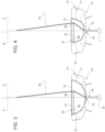
Figure 3 is a cross section, on an enlarged scale and with parts removed for the sake of clarity, along the line III-III inFigure 2 ; -
Figure 4 is a cross section, on an enlarged scale and with parts removed for the sake of clarity, along the line IV-IV inFigure 2 ; -
Figure 5 is a schematic cross section, on an enlarged scale and with parts removed for clarity, along the line V-V inFigure 2 , wherein various positions that can be obtained for two bow sail elements can be seen; -
Figure 6 is a schematic cross section, on an enlarged scale and with parts removed for the sake of clarity, along the line V-V inFigure 2 ; and -
Figure 7 is a simplified perspective view, with parts schematically depicted, similar toFigure 2 and relating to a second preferred embodiment of the single-hull sailing boat produced according to the precepts of this invention. - In
Figures 2 ,3 ,4 , and6 ,reference number 10 indicates, as a whole, a single-hull sailing boat produced according to the precepts of the present invention and partially illustrated with schematically depicted parts. - The
boat 10 comprises ahull 11 extending along a longitudinal axis X between a front end or bow, indicated by thereference number 12, and a rear end, or stern, indicated by thereference number 13. The longitudinal axis X coincides with a normal sailing direction V of theboat 10. - The
hull 11 also extends by width and height according to a transverse axis Y and a vertical axis Z, perpendicular to each other and to the longitudinal axis X, so as to form a Cartesian tern of orthogonal axes, fixed in relation to thehull 11. The longitudinal axis X, the transverse axis Y, and the vertical axis Z are commonly called the roll axis, the pitch axis, and the yaw axis, respectively. - The
hull 11 is laterally delimited byopposite sides bow 12 and thestern 13, and is normally closed above by adeck 16. - The
boat 10 also preferably comprises akeel 18, which projects downwards along an axis parallel to the vertical axis Z starting from aportion 19 of thehull 11 arranged in a position interposed between thebow 12 and thestern 13, and centrally between thesides hull 11. In particular, theportion 19 is the lowest part of thehull 2. Thekeel 18 preferably has a lower end that supports or defines abulb 20, which has a mass (for example, approximately 8-10 tonnes) so that the centre of gravity of theboat 10 is in a relatively low position, in particular to enable self-righting of theboat 10 even if it totally capsizes. - The
boat 10 is preferably of the kind adapted for offshore sailing competitions and is thus provided with side arms, which are known and not illustrated, provided with respective hydrofoils or, more simply, foils (also known and not illustrated) and connected to thehull 11 so as to be independently mobile between a lowered position, wherein they immerse the foil in water, and a raised position, wherein they maintain the foil outside of the water. - When both foils are in the raised position, generally to reduce their resistance when there is little wind, in which listing does not need to be countered more than what the
bulb 20 does and, in any case, enough vertical load could not be generated to raise thehull 11 from the water, theboat 10 assumes a condition of displacement sailing. - The
boat 10 also comprises a mainmast 21 extending parallel to the vertical axis Z and projecting upwards from thehull 11 and from thedeck 16, and amainsail 22 of a conventional type rigged in a known way to themainmast 21. In particular, themainmast 21 is configured, in cross section (Figures 5 and6 ), according to a predetermined symmetric biconvex airfoil. While sailing, themainmast 21 and the mainsail 22 have respectiveopposite surfaces Figure 6 ), which are arranged windward and leeward, respectively, and define, as a whole, a wind-exposed profile P. - Advantageously, the boat 1 also comprises one or more bow sail elements, in the example illustrated two indicated respectively with the
reference numbers bow 12, are configured, in each cross section, according to predetermined airfoils Q1, Q2 (Figures 5 and6 ), and define respective high-lift devices or slats in relation to the profile (P, Q1) immediately adjacent to the stern. - In practice, the
bow sail elements boat 10, defined by the mainsail 22 and bowsail elements - In more general terms, each
bow sail element - As can be seen in
Figures 2 ,5 , and6 , thebow sail elements opposite surfaces - In particular, the
bow sail element 25 is placed immediately adjacent to themainmast 21 and defines, with the latter, aslit 27 with predetermined dimensions to enable, while sailing, the passage of a given airflow at high speed on theleeward surfaces mainsail 22, which is able to reduce the turbulence in contact with theleeward surfaces - The bow sail element 26 (thus, the airfoil Q2) is, instead, placed in front of the
bow sail element 25, precisely between the latter and thebow 12, and thus defines a slat, in each cross section in relation to the corresponding airfoil Q1 of thebow sail element 25. - The
bow sail element 26 defines aslit 28 with predetermined dimensions with thebow sail element 25 to enable, while sailing, the passage of a given airflow at least on theleeward surface 25b of thebow sail element 25, of the mainmast 21 andmainsail 22, which can reduce the turbulence in contact with theleeward surface - The
bow sail element 25 preferably comprises: - a
support element 29 with an oblong shape along a respective main extension direction A prevailing over the other directions, which is arranged in front of the mainmast 21 and projects upwards from thehull 11 along the above-mentioned main extension direction A; - a plurality of
ribs 31, each defining a respective airfoil Q1 carried crosswise, in a projecting manner, by thesupport element 29 in parallel positions and spaced apart from one another along the main extension direction A of thesupport element 29; and - a
sail 33 fitted on theribs 31 like a sack open at its opposite ends to form a respective closed loop around theribs 31. - In the example illustrated, the airfoils Q1 of the
ribs 31 have gradually tapered dimensions moving upwards, to be fitted by atriangular sail 33; according to a possible alternative that is not illustrated, the airfoils Q1 of theribs 31 could also have constant dimensions. - The airfoils Q1 of the
ribs 31 are preferably concave-convex. According to a possible alternative not illustrated, the airfoils Q1 of theribs 31 could be symmetric biconvex. - According to a possible alternative not illustrated, the
sail 33 of thebow sail element 25 could also be conventional, or "one-dimensional". - Similarly to what was seen for the
bow sail element 25, the otherbow sail element 26 also, preferably, comprises: - a
support element 30 with an oblong shape along a respective main extension direction B prevailing over the other directions, which is arranged in front of the mainmast 21 and thesupport element 29 and projects upwards from thehull 11 along the above-mentioned main extension direction B; - a plurality of
ribs 32, each defining a respective airfoil Q2, carried crosswise, in a projecting manner, by thesupport element 30 in parallel positions and spaced apart from one another along the main extension direction B of thesupport element 30; and - a
sail 34 fitted on theribs 32 like a sack open at its opposite ends to form a respective closed loop around theribs 32. - In the example illustrated, the airfoils Q2 of the
ribs 32 have gradually tapered dimensions moving upwards, to be fitted by atriangular sail 34; according to a possible alternative that is not illustrated, the airfoils Q2 of theribs 32 could also have constant dimensions. - The airfoils Q2 of the
ribs 32 are preferably symmetric biconvex. According to a possible alternative not illustrated, the airfoils Q2 of theribs 32 could be concave-convex. - In the example illustrated, the
support elements 29, 30 (Figures 2 ,3, and 4 ) are stays connecting anupper end portion 21c of the mainmast 21 to a bow portion of thehull 11. - The main extension directions A, B prevailing over the
support elements - With reference to
Figures 2 to 4 , theboat 10 also comprises one ormore actuator members 35 to move theribs support elements - In the example illustrated, an
actuator member 35 is used to move thesupport element 29 and anotheractuator member 35 to move thesupport element 30. - The
actuator members 35 are both placed within thehull 11 under the deck and consist of fluidic, pneumatic, or hydraulic cylinders, extending parallel to the transverse axis Y. - Each
actuator member 35 comprises asleeve 36, fixed at one of its ends to thehull 11, and apiston 37 equipped with a rod, projecting from one opposite end of thesleeve 36 and having onefree end 38 cooperating in contact with thecorresponding support element hull 11. - Both
support elements grooves deck 16 and shaped like cams to define the movement trajectories of thesupport elements - In the example illustrated in
Figures 2 to 4 , thegroove 39 has a straight trajectory parallel to the transverse axis Y, while theother groove 40 has a curved trajectory with a concavity facing thegroove 39. - The positions that can be obtained by the
support elements ribs elements respective grooves Figure 5 . These positions may be changed as a function of the apparent wind direction while sailing. In particular, in the event of turns or jibing, the profiles Q1, Q2 may be oriented to the wind on the opposite tacks by moving theribs Figures 3 and 4 ) along thegrooves ribs - In particular, according to a possible alternative not illustrated, the connection of the
ribs hull 11 and thebow sail elements ribs hull 11. - According to an additional possible alternative not illustrated, each
rib bow sail element - changing the angle of inclination of each
rib support element - changing the shape of the external skin of each
rib - With reference to
Figure 6 , when theboat 10 is sailing under the thrust of the wind, thebow sail elements Figure 1 . - Also indicating, for the
boat 10, the sailing direction with V and the apparent wind direction with W, the total forces FE1 and FE2 that act on the twobow sail elements bow sail elements - There is, thus, a significant improvement in the use of the wind force in the sailing direction V with a resulting increase in the speed of the
boat 10 compared to the known boats like that illustrated inFigure 1 and designated with reference number 1. - In practice, the
bow sail elements mainmast 21 while sailing. - Compared to a conventional sailing boat like that designated with reference number 1 in
Figure 1 , thejib 5 is actually replaced by twobow sail elements slit 28 and shaped, in each cross section, according to predetermined airfoils Q1, Q2. In this way, themainmast 21 and the mainsail 22 become a main surface and an outlet flap for the airflow while sailing in relation to the slats on the leading edge. The effect of this solution is to orient the aerodynamic load vector more in the sailing direction V of theboat 10. - In practice, the curvature of the profile P is moved ahead of the mainmast 21 creating profiling continuity with the mainsail 22, on the side facing the stern, and with the
bow sail elements - The
bow sail elements mainsail 22, make it possible to better cope with gusts of wind, changes in the angle of incidence that the wind continually causes, and small changes in direction associated with the rudder in variable conditions that occur in offshore regattas. - In addition, the possibility of changing the incidence of the
bow sail elements boat 10 in changeable conditions, adapting it more easily to the changes in the apparent wind direction and avoiding the need to use more conventional sails like Spinnakers, in particular with high incidences of the apparent wind. - In addition, the "two-dimensional" profiles of the
bow sail elements - In any case, as specified above, the
bow sail element 25 could also include a conventional, "single-dimensional"sail 33. - Finally, being able to operate on the
bow sail elements actuator members 35, it is possible to very finely adjust the attitude of the sail system, reducing the need to adjust the mainsail 22 and the enormous loads associated with it on regatta boats. - With reference to
Figure 7 , the reference number 10' indicates, as a whole, a sailing boat according to an alternative embodiment of the present invention. - Since the boat 10' is entirely similar to the
boat 10, only the distinctive features compared to the latter will be described below, indicating, where possible, components and parts corresponding or equivalent to those already described with the same reference numbers. - In particular, the boat 10' differs from the boat 1 essentially in that the mainsail 22 is partially detached from the mainmast 21 along part of the height of the latter and, precisely, along the part nearest the
deck 16; along this part, the mainsail 22 and the mainmast 21 delimit, between them, aslit 41, which can be used to further orient the drive force deriving from the thrust of the wind in the sailing direction or in the forward direction V of the boat 10' . - Lastly, it is clear that modifications and variations may be made to the
boats 10, 10' described and illustrated with reference to the attached figures without departing from the scope of protection defined by the claims included hereinafter. - In particular, as mentioned above, the external forms of the
ribs bow sail elements boats 10, 10' may be different from what is schematically illustrated here by way of non-limiting example.
by rotating, around the corresponding
Claims (12)
- A sailing boat (10, 10') comprising:- a hull (11) extending between a stern (13) and a bow (12) along a longitudinal axis (X) coinciding with a normal sailing direction (V) of the boat (10, 10');- a mainmast (21) projecting upwards from said hull (11) and extending parallel to a vertical direction (Z), which is orthogonal to said longitudinal direction (X);- a mainsail (22) rigged on said mainmast (21); wherein, while sailing, said mainmast (21) and said mainsail (22) have opposite surfaces (21a, 21b; 22a, 22b), which are arranged windward and leeward, respectively, and define, as a whole, a wind-exposed profile (P);- at least one bow sail element (25), which is arranged in front of said mainmast (21), between the mainmast (21) and said bow (12), is configured, in each cross section, according to a predetermined airfoil (Q1) and defines a slat relative to the leading edge of the wind-exposed profile (P) defined by said mainmast (21) and by said mainsail (22);characterised in that said at least one bow sail element (25) comprises:- a support element (29) with an oblong shape along a main extension direction (A) prevailing over the other directions, which is arranged in front of said mainmast (21) and projects upwards from said hull (21) along said main extension direction (A);- a plurality of ribs (31), each defining said airfoil (Q1), carried crosswise, in a projecting manner, by said support element (29) in parallel positions and spaced apart from one another along said main extension direction (A) of the support element (29); and- a sail (33) fitted on said ribs (31) in order to form a closed loop around them.
- The boat according to claim 1, wherein said at least one bow sail element (25) defines a slit (27) with predetermined dimensions with said mainmast (21) so as to allow, while sailing, a given airflow to flow on the leeward surfaces (21b, 22b) of the mainmast and of the mainsail (21, 22), in order to reduce turbulences in contact with said leeward surfaces (21b, 22b).
- The boat according to claim 1 or 2, wherein the airfoil (Q1) of each one of said ribs (31) is concave-convex.
- The boat according to claim 1 or 2, wherein the airfoil (Q1) of each one of said ribs (31) is mono-dimensional.
- The boat according to any of the preceding claims, further comprising a further bow sail element (26), which is arranged in front of said at least one bow sail element (25), between the latter and said bow (12), is configured, in each cross section, according to a further predetermined airfoil (Q2) and defines an additional slat at least relative to the leading edge of the airfoil (Q1) defined by said at least one bow sail element (25).
- The boat according to claim 5, wherein said further bow sail element (26) defines a further slit (28) with predetermined dimensions with said at least one bow sail element (25) so as to allow, while sailing, a given airflow to flow on the leeward surface (25b) of said at least one bow sail element (25), in order to reduce turbulences in contact with said leeward surfaces (25b, 21b, 22b).
- The boat according to either claim 5 or 6, wherein said additional bow sail element (26), similarly to said at least one bow sail element (25) comprises:- an additional support element (30) with an oblong geometry along an additional main extension direction (B) prevailing over the other directions, which is arranged in front of said mainmast (21) and projects upwards from said hull (21) along said additional main extension direction (B) ;- a plurality of additional ribs (32), each defining said additional airfoil (Q2), carried crosswise, in a projecting manner, by said additional support element (30) in parallel positions and spaced apart from one another along said additional main extension direction (B) of the additional support element (30); and- an additional sail (34) fitted on said additional ribs (32) in order to form a closed loop around them.
- The boat according to claim 7, wherein said support element (29, 30) of each one of said bow sail elements (25, 26) is a stay connecting an upper end portion (21c) of said mainmast (21) to a bow portion of said hull (11).
- The boat according to claim 7 or 8, wherein said additional airfoil (Q2) of each said additional rib (32) is at least symmetric biconvex.
- The boat according to any one of the claims from 7 to 9, comprising one or more actuator members (35) to move said ribs (31, 32) and/or said support element/s (29, 30) along planes that are transverse to said longitudinal axis (X) and to said vertical axis (Z).
- The boat according to claim 10, wherein said one or more actuator members (35) cooperate with said ribs (31, 32) by means of one or more intermediate connection element connecting them to the hull (11).
- The boat according to any one of the preceding claims, wherein said mainsail (22) is partially detached from said mainmast (21) along part of the height thereof and delimits, with the mainmast (21), a slit (41) with predetermined dimensions.
Applications Claiming Priority (1)
| Application Number | Priority Date | Filing Date | Title |
|---|---|---|---|
| IT102023000019104A IT202300019104A1 (en) | 2023-09-18 | 2023-09-18 | BOAT WITH AN IMPROVED SAIL SYSTEM |
Publications (1)
| Publication Number | Publication Date |
|---|---|
| EP4524022A1 true EP4524022A1 (en) | 2025-03-19 |
Family
ID=89308360
Family Applications (1)
| Application Number | Title | Priority Date | Filing Date |
|---|---|---|---|
| EP24200767.2A Pending EP4524022A1 (en) | 2023-09-18 | 2024-09-17 | Boat with improved sail system |
Country Status (3)
| Country | Link |
|---|---|
| EP (1) | EP4524022A1 (en) |
| IT (1) | IT202300019104A1 (en) |
| WO (1) | WO2025062280A1 (en) |
Citations (7)
| Publication number | Priority date | Publication date | Assignee | Title |
|---|---|---|---|---|
| US4437426A (en) * | 1981-12-21 | 1984-03-20 | Fiberglass Unlimited, Inc. | Wing type air foil assembly |
| SU1178649A1 (en) * | 1982-04-27 | 1985-09-15 | Предприятие П/Я А-1459 | Sailing ship truss mast |
| US4685410A (en) * | 1985-04-08 | 1987-08-11 | Fuller Robert R | Wing sail |
| WO1988010208A1 (en) * | 1987-06-27 | 1988-12-29 | Yukimasa Hori | Sailboat |
| US4803939A (en) * | 1987-08-28 | 1989-02-14 | Christopher Gardner | Slot-forming foil construction for sailing yachts |
| US5249542A (en) * | 1992-06-03 | 1993-10-05 | Latham Ronald D | Cambered airfoil, and craft comprising same |
| US10392088B2 (en) | 2014-06-18 | 2019-08-27 | Cws Morel | Wing for the propulsion of a vehicle |
-
2023
- 2023-09-18 IT IT102023000019104A patent/IT202300019104A1/en unknown
-
2024
- 2024-09-17 EP EP24200767.2A patent/EP4524022A1/en active Pending
- 2024-09-17 WO PCT/IB2024/059011 patent/WO2025062280A1/en not_active Ceased
Patent Citations (7)
| Publication number | Priority date | Publication date | Assignee | Title |
|---|---|---|---|---|
| US4437426A (en) * | 1981-12-21 | 1984-03-20 | Fiberglass Unlimited, Inc. | Wing type air foil assembly |
| SU1178649A1 (en) * | 1982-04-27 | 1985-09-15 | Предприятие П/Я А-1459 | Sailing ship truss mast |
| US4685410A (en) * | 1985-04-08 | 1987-08-11 | Fuller Robert R | Wing sail |
| WO1988010208A1 (en) * | 1987-06-27 | 1988-12-29 | Yukimasa Hori | Sailboat |
| US4803939A (en) * | 1987-08-28 | 1989-02-14 | Christopher Gardner | Slot-forming foil construction for sailing yachts |
| US5249542A (en) * | 1992-06-03 | 1993-10-05 | Latham Ronald D | Cambered airfoil, and craft comprising same |
| US10392088B2 (en) | 2014-06-18 | 2019-08-27 | Cws Morel | Wing for the propulsion of a vehicle |
Also Published As
| Publication number | Publication date |
|---|---|
| IT202300019104A1 (en) | 2025-03-18 |
| WO2025062280A1 (en) | 2025-03-27 |
Similar Documents
| Publication | Publication Date | Title |
|---|---|---|
| KR102768978B1 (en) | Propulsion device | |
| US5163377A (en) | Sailing yacht | |
| DK2771233T3 (en) | Hydrodynamic flow control flow at the bow of a vessel | |
| US20110168071A1 (en) | System and method of adjusting the location and position of the foresail on a sailboat | |
| US20040099196A1 (en) | Marine craft towed by a kite-type canopy | |
| AU2008226586A1 (en) | Apparatus and method to optimize sailing efficiency | |
| CA3043137A1 (en) | Ship with sail propulsion | |
| US20130014683A1 (en) | Adjusting rigid foil spar system | |
| US3968765A (en) | Rotatable-mounting apparatus for sails | |
| US20080245284A1 (en) | Three Degree-of-Freedom Pivot Assembly, Sail-Mounted Ballast, and Sail Control System for High Speed Sailboats | |
| US4453483A (en) | Sail assembly for vessels | |
| US6732670B2 (en) | Sailing craft | |
| US7311059B2 (en) | Watercraft hull with entrapment tunnel | |
| WO2025062280A1 (en) | Boat with improved sail system | |
| EP4574642A1 (en) | Mainmast of a sailing boat | |
| EP4574643A1 (en) | Main mast of a sailing boat | |
| US4945845A (en) | High-speed sailing craft | |
| US6662738B2 (en) | Lifting-sail boat apparatus and method | |
| EP4177143A1 (en) | Foldable hydrofoil for boats | |
| US4886008A (en) | Frame spar for soft airfoils | |
| EP2752360A2 (en) | Improved sailing vessel | |
| US7841285B2 (en) | Waterborne vessel with loop keel | |
| WO2022064195A1 (en) | A wing sail for a wing propelled craft | |
| WO2025244551A1 (en) | Sail system and sail system operating method | |
| RU2827744C1 (en) | Sailing system |
Legal Events
| Date | Code | Title | Description |
|---|---|---|---|
| PUAI | Public reference made under article 153(3) epc to a published international application that has entered the european phase |
Free format text: ORIGINAL CODE: 0009012 |
|
| STAA | Information on the status of an ep patent application or granted ep patent |
Free format text: STATUS: THE APPLICATION HAS BEEN PUBLISHED |
|
| AK | Designated contracting states |
Kind code of ref document: A1 Designated state(s): AL AT BE BG CH CY CZ DE DK EE ES FI FR GB GR HR HU IE IS IT LI LT LU LV MC ME MK MT NL NO PL PT RO RS SE SI SK SM TR |
|
| STAA | Information on the status of an ep patent application or granted ep patent |
Free format text: STATUS: REQUEST FOR EXAMINATION WAS MADE |
|
| 17P | Request for examination filed |
Effective date: 20250916 |
|
| STAA | Information on the status of an ep patent application or granted ep patent |
Free format text: STATUS: EXAMINATION IS IN PROGRESS |
|
| 17Q | First examination report despatched |
Effective date: 20251222 |