EP4523995A1 - System for the transmission of energy and data for steering wheels of boats - Google Patents
System for the transmission of energy and data for steering wheels of boats Download PDFInfo
- Publication number
- EP4523995A1 EP4523995A1 EP24200167.5A EP24200167A EP4523995A1 EP 4523995 A1 EP4523995 A1 EP 4523995A1 EP 24200167 A EP24200167 A EP 24200167A EP 4523995 A1 EP4523995 A1 EP 4523995A1
- Authority
- EP
- European Patent Office
- Prior art keywords
- steering wheel
- control unit
- transmission
- transmission means
- vessel
- Prior art date
- Legal status (The legal status is an assumption and is not a legal conclusion. Google has not performed a legal analysis and makes no representation as to the accuracy of the status listed.)
- Pending
Links
Images


Classifications
-
- B—PERFORMING OPERATIONS; TRANSPORTING
- B63—SHIPS OR OTHER WATERBORNE VESSELS; RELATED EQUIPMENT
- B63H—MARINE PROPULSION OR STEERING
- B63H25/00—Steering; Slowing-down otherwise than by use of propulsive elements; Dynamic anchoring, i.e. positioning vessels by means of main or auxiliary propulsive elements
- B63H25/02—Initiating means for steering, for slowing down, otherwise than by use of propulsive elements, or for dynamic anchoring
-
- B—PERFORMING OPERATIONS; TRANSPORTING
- B60—VEHICLES IN GENERAL
- B60R—VEHICLES, VEHICLE FITTINGS, OR VEHICLE PARTS, NOT OTHERWISE PROVIDED FOR
- B60R16/00—Electric or fluid circuits specially adapted for vehicles and not otherwise provided for; Arrangement of elements of electric or fluid circuits specially adapted for vehicles and not otherwise provided for
- B60R16/02—Electric or fluid circuits specially adapted for vehicles and not otherwise provided for; Arrangement of elements of electric or fluid circuits specially adapted for vehicles and not otherwise provided for electric constitutive elements
- B60R16/023—Electric or fluid circuits specially adapted for vehicles and not otherwise provided for; Arrangement of elements of electric or fluid circuits specially adapted for vehicles and not otherwise provided for electric constitutive elements for transmission of signals between vehicle parts or subsystems
- B60R16/027—Electric or fluid circuits specially adapted for vehicles and not otherwise provided for; Arrangement of elements of electric or fluid circuits specially adapted for vehicles and not otherwise provided for electric constitutive elements for transmission of signals between vehicle parts or subsystems between relatively movable parts of the vehicle, e.g. between steering wheel and column
-
- H—ELECTRICITY
- H02—GENERATION; CONVERSION OR DISTRIBUTION OF ELECTRIC POWER
- H02J—ELECTRIC POWER NETWORKS; CIRCUIT ARRANGEMENTS OR SYSTEMS FOR SUPPLYING OR DISTRIBUTING ELECTRIC POWER; SYSTEMS FOR STORING ELECTRIC ENERGY
- H02J9/00—Circuit arrangements for emergency or stand-by power supply, e.g. for emergency lighting
- H02J9/002—Circuit arrangements for emergency or stand-by power supply, e.g. for emergency lighting in which a reserve is maintained in an energy source by disconnecting non-critical loads, e.g. maintaining a reserve of charge in a vehicle battery for starting an engine
-
- B—PERFORMING OPERATIONS; TRANSPORTING
- B63—SHIPS OR OTHER WATERBORNE VESSELS; RELATED EQUIPMENT
- B63H—MARINE PROPULSION OR STEERING
- B63H20/00—Outboard propulsion units, e.g. outboard motors or Z-drives; Arrangements thereof on vessels
- B63H20/08—Means enabling movement of the position of the propulsion element, e.g. for trim, tilt or steering; Control of trim or tilt
- B63H20/12—Means enabling steering
-
- B—PERFORMING OPERATIONS; TRANSPORTING
- B63—SHIPS OR OTHER WATERBORNE VESSELS; RELATED EQUIPMENT
- B63H—MARINE PROPULSION OR STEERING
- B63H25/00—Steering; Slowing-down otherwise than by use of propulsive elements; Dynamic anchoring, i.e. positioning vessels by means of main or auxiliary propulsive elements
- B63H25/02—Initiating means for steering, for slowing down, otherwise than by use of propulsive elements, or for dynamic anchoring
- B63H2025/022—Steering wheels; Posts for steering wheels
Definitions
- the present invention relates to a System for the transmission of energy and data for vessel steering wheels, comprising a first part mounted integral with the dashboard of the vessel and a second part mounted integral with the steering wheel.
- the first part comprises first transmission means connected to a power source mounted on board the vessel, while the second part comprises second transmission means connected to a system for exploiting the energy and data transmitted.
- first and second transmission means are configured to transmit the electric current from the power source to the exploitation system.
- the first part can be integral with the dashboard or the wheelhouse, that is, it has no relative movement with respect to the dashboard.
- the first control unit In case of detection of the current absorbed by the exploitation system, it is possible to set a threshold value in the first control unit, so that the first control unit activates the switch means in case the current absorbed by the exploitation system falls below the threshold value.
- This configuration also makes it possible to make a safety system, in such a way that too high current absorptions are not envisaged, which could be due to a failure of the components or a malfunction of the system.
- the first control unit sets a voltage threshold value below which it activates the switch means, so as to interrupt the transmission of energy from the power source to the first and/or second transmission means.
- the voltage threshold value identifies the state of the battery, i.e. it indicates whether the battery is being charged, for example through the alternators of the propulsion engines, or whether the battery is not being charged.
- the first control unit in such a way that the energy transmission can only take place in the event that the battery is being charged, so that this transmission will not excessively discharge the battery, which can be used for main services, such as starting propulsion engines.
- the energy transmission system subject-matter of the present invention may be inactive in the event that the battery is not being charged, preserving it from unwanted discharges.
- the switch means are interposed between the first control unit and the first transmission means, so that, if the switch means are activated, the first control unit can always be powered, i.e. remain in standby, but absorbing a minimum current value, as the exploitation system will be disconnected.
- the system subject-matter of the present invention allows to transmit electric current from a fixed part integral with the dashboard of the vessel, to a movable part, integral with the steering wheel, in order to use this electric current also as information transport.
- the exploitation system can consist of any electronic device, such as a display aimed at displaying any information.
- This solution makes it possible to transform the steering wheel into a smart steering wheel, i.e. it has on-board electronics that allow a user to interact with one or more components of the vessel.
- the transmission system subject-matter of the present invention is used to make a heated steering wheel.
- Both the first and the second control unit can be made in the form of electronic boards with microprocessors.
- the presence of the second control unit allows to make the transmission system particularly adaptable to different configurations, since, in addition to providing heating to the handle of the steering wheel, it can handle additional electronic devices, such as a display.
- the transformation from alternating current to direct current at the steering wheel level has particular advantages in the event that the transmission means consist of electromagnetic transmission means.
- the possibility of working in direct current at the level of the steering wheel is particularly advantageous, since the alternating current could create electromagnetic disturbances.
- the second control unit allows to implement controls and adjustments regarding the possibility of heating the handle of the steering wheel.
- the exploitation system comprises a second resistive element consisting of a wire, which extends along at least part of the length of the handle of the steering wheel.
- the first and second resistive element are connected in parallel and can be controlled by the second control unit.
- the first and second resistive element can be used alternatively or in combination, so as to modify the heating of the handle of the steering wheel.
- the second control unit may be configured for the alternating or simultaneous activation of the first and second conductive element on the basis of the voltage value detected by the voltage detection means.
- the means for detecting the voltage of the power source i.e. of the battery, can evaluate whether the system is connected to a nominal 24 Volt or 12 Volt battery.
- the second control unit activates both resistive elements, so as to absorb half the amount of electric current.
- the presence of a 24V battery allows making a more performing system, which allows the handle of the steering wheel to be heated faster.
- the presence of the second control unit makes it possible to implement safety controls relating to the heating of the handle.
- the threshold value can be relative to a threshold value with an upper limit, i.e. a temperature value not to be exceeded, at which the heating is interrupted, as well as a threshold value with a lower limit, i.e. a minimum temperature value below which the heating must be started.
- the system subject-matter of the present invention may comprise an ambient temperature sensor, i.e. a sensor configured to detect the temperature in a non-heated zone.
- the first and/or the second control unit provide associative tables between the values of the threshold values and the values of the ambient temperature.
- the system subject-matter of the present invention comprises means for enabling the first control unit.
- these enabling means can be integrated into the ignition system of the vessel, making a "subkey" system that can be activated only in the case of ignition of the vessel.
- the transmission means may consist of electromagnetic induction means.
- the transmission means consist of a system with sliding contacts.
- the system with sliding contacts can be positioned in any way between the first and second part.
- the first and second transmission means consist of two or more conductive tracks arranged on planes parallel to each other and perpendicular to the axis of rotation of the steering wheel.
- the conductive tracks have sliding contacts configured to put into contact the conductive tracks placed on parallel planes.
- the peculiar positioning of the conductive tracks allows the transmission means to be inserted into a restricted space, the space between the steering wheel and the dashboard of the vessel, as required by current regulations.
- the sliding contacts consist of a plurality of lamellae that extend from a conductive track to the corresponding facing conductive track, the lamellae being alternately oriented according to different directions.
- This configuration allows to always have the same number of tabs that put into contact one conductive track and the other, regardless of the direction of rotation of the steering wheel, optimizing the transmission from the first to the second transmission means.
- system subject-matter of the present invention may provide a plurality of controls, placed on the dashboard of the vessel and/or on the steering wheel, for setting the operation of the first and/or second control unit.
- the second control unit could be configured to activate both resistive elements up to a first temperature threshold value, and then activate only one until a second threshold value is reached, and then deactivate both of them.
- the power source is connected to the first transmission means through electrical connection cables.
- the packing of the components of the system causes a drag force between the second part and the first part during the rotation of the steering wheel.
- first part tends to have a relative rotation with respect to the dashboard, while the second part tends to have a relative rotation with respect to the steering wheel.
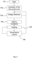
- Figure 2 illustrates a block diagram of a possible generic operation of the system subject-matter of the present invention.
- step 101 the system is started, step 101, for example by igniting the vessel.
- the battery 31 is then activated, which powers and activates the first control unit 13, step 102.
- the control unit 13 detects, through the detection means 33, the voltage at the ends of the battery 31, step 103, and compares the detected value with the threshold value.
- the control unit 13 remains in standby, waiting for the detected voltage value to be greater than the threshold value.
- step 104 the system waits for a command from the user, step 104, that is, in the illustrated variant, it waits for the user to decide whether to heat the handle of the steering wheel.
- control unit 20 can warn the control unit 13, which, if there are acceptable voltage values, reactivates the heating.
- the first and second transmission means must guarantee the transmission of the electrical signal allowing an infinite number of turns of the steering wheel around the axis A.
- the first and second transmission means must be positioned between the first 12 and the second part 22, in a particularly restricted space.
- the first and second transmission means consist of two pairs of conductive tracks arranged on planes parallel to each other and perpendicular to the axis of rotation A of the steering wheel.
- the two pairs of conductive tracks are positioned between the first portion 12 and the second portion 22 in the gap 112.
- sliding contacts configured to put into contact the conductive tracks placed on parallel planes.
- Figures 4a to 4c illustrate a possible embodiment of such conductive tracks, in particular of a single pair of conductive tracks, i.e. that with the sliding contacts.
- the conductive tracks are formed by two annular elements 121 and 122, arranged concentric to each other.
- Both the annular elements 121 and 122 have sliding contacts consisting of tabs 123 and 124 which are obtained with the metal layer constituting the annular elements 123 and 124.
- the tabs are arranged on incident planes with respect to the plane of the annular elements 121 and 122 precisely to allow the annular elements themselves to be in contact with corresponding annular elements placed parallel to the annular elements 121, 122.
- the tabs 123 and 124 will be with one end fixed to the annular elements 121 and 122 and with the other end (the free end) will slide along the surface of the annular elements above, in order to allow contact by sliding during the rotation of the steering wheel.
- a plurality of tabs 123 and 124 placed on the surface of the annular members 121 and 122 is provided.
- the lamellae 123 are all oriented in the same direction, the same inclination, but in a different direction with respect to the lamellae 124.
- the lamellae 123 and 124 lie on planes inclined with respect to the planes of the annular elements 121 and 122 and that they are convergent with each other.
- the annular elements 121 and 122 have elements for connection 125 and 126 to the switch means 11 and to the control unit 13.
- annular elements 121 and 122 illustrated in the figures constitute the first transmission means, while the second transmission means will consist of further smooth annular elements, without tabs, placed above and parallel to the annular elements 121 and 122.
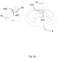
- Figure 3a illustrates a possible embodiment of the means for locking the first part to the pilot bridge of the vessel.
- Number 15 indicates the cable of connection from the battery to the first transmission means, supported by a first bracket 42 mounted fixed with respect to the wheelhouse 42 and the steering wheel 2 being rotatable with respect to said first bracket 42.
- number 42 indicates the wheelhouse, integral with the dashboard, which may have devices such as tilts, hydraulic pumps or similar devices, known to the state of the art and commonly used in wheelhouses known to the state of the art.
- bracket 40 mounted integral with the wheelhouse 42 provided with two pins 401, preferably made in piece with the bracket 40.
Landscapes
- Engineering & Computer Science (AREA)
- Mechanical Engineering (AREA)
- Chemical & Material Sciences (AREA)
- Combustion & Propulsion (AREA)
- Ocean & Marine Engineering (AREA)
- Business, Economics & Management (AREA)
- Emergency Management (AREA)
- Power Engineering (AREA)
- Steering Controls (AREA)
Abstract
System for the transmission of energy and data for vessel steering wheels, comprising a first part (12) mounted integral with the dashboard (1) of the vessel and a second part (22) mounted integral with the steering wheel, said first part (12) comprising first transmission means connected to a power source (31) mounted on board the vessel.
The second part (22) comprises second transmission means connected to a system for exploiting the energy and data transmitted, the first and second transmission means being configured to transmit the electric current from the power source (31) to the exploitation system.
There are also means for detecting (33) the voltage of the power source (31) and/or of the current absorbed by said exploitation system, there being provided a first control unit (13) comprising first switch means (11) configured to activate/deactivate the connection of the first transmission means to the power source (31), which switch means (11) are operated on the basis of the value detected by the detection means (33) .
Description
- The present invention relates to a System for the transmission of energy and data for vessel steering wheels, comprising a first part mounted integral with the dashboard of the vessel and a second part mounted integral with the steering wheel.
- The first part comprises first transmission means connected to a power source mounted on board the vessel, while the second part comprises second transmission means connected to a system for exploiting the energy and data transmitted.
- Further, the first and second transmission means are configured to transmit the electric current from the power source to the exploitation system.
- It should be specified that the first part can be integral with the dashboard or the wheelhouse, that is, it has no relative movement with respect to the dashboard.
- The one just disclosed is the common configuration used in the systems mounted on board vessels for the transmission of electrical energy.
- Generally, these systems are used to make heated steering wheels, that is, steering wheels in which the handle is heated, thanks to the presence of resistive elements embedded in the handle that generate heat if traversed by current.
- Examples of solutions known to the state of the art are disclosed in documents
US20190084502 ,US20090224523 andIT102013902128136 - The installation of energy and data transmission systems in the nautical field, i.e. on vehicles such as vessels or similar, involves specific problems of the marine environment.
- First of all, it is necessary to use electronic components, in an aggressive environment, such as the marine environment, in which the salt causes the corrosion of the metals constituting these electronic components.
- The salt spray, formed by dispersions of salt water in the air, manages to creep inside interstices, even the small ones.
- Insulating metal parts is therefore a crucial factor for energy transmission systems mounted on board vessels, a feature which, however, is in contrast to the need to provide for moving parts, such as the rotation of the steering wheel with respect to the dashboard, where the electronic parts must interface and cannot be completely insulated.
- In addition, in vessels known to the state of the art, a particularly important factor is the protection of the power battery(ies), which also provide(s) power supply to the energy transmission systems.
- In fact, it is essential that these energy transmission systems do not excessively overload the battery, compromising its operation for essential functions such as starting the propulsion engines.
- At the moment there are no energy and data transmission systems on the market that can be installed on board vessels and that are particularly efficient, without their operation impacting on further essential functions of the vessel.
- There is therefore a need not met by the systems known to the state of the art to make an energy transmission system that solves the disadvantages set out above, that is, which can be installed efficiently on board vessels, avoiding that the aggressive environment impairs their operation and without compromising the charging quality of the vessel's battery.
- The present invention achieves the above objects by making a system as disclosed above, in which there are means for detecting the voltage of the power source and/or of the current absorbed by said exploitation system.
- There is further provided a first control unit comprising first switch means configured to activate/deactivate the connection of the first transmission means to the power source.
- In addition, the switch means are operated on the basis of the value detected by the detection means.
- The detection means can therefore identify voltage values at the level of the power source and/or values of current absorbed by the exploitation system.
- These modes can be provided alternatively or in combination.
- In case of detection of the current absorbed by the exploitation system, it is possible to set a threshold value in the first control unit, so that the first control unit activates the switch means in case the current absorbed by the exploitation system falls below the threshold value.
- This configuration also makes it possible to make a safety system, in such a way that too high current absorptions are not envisaged, which could be due to a failure of the components or a malfunction of the system.
- In fact, in the event of malfunction or short circuits, the detection of "abnormal" values involves interrupting the connection between the steering wheel and the power source, safeguarding the integrity of the steering wheel itself and its components.
- According to a preferred embodiment variant, the detection means are aimed at identifying the voltage values at the ends of the power source.
- Based on what has been disclosed, it is evident that the first control unit can be provided both at the steering wheel level and at the dashboard or wheelhouse level.
- Advantageously, according to this variant, the first control unit sets a voltage threshold value below which it activates the switch means, so as to interrupt the transmission of energy from the power source to the first and/or second transmission means. The voltage threshold value identifies the state of the battery, i.e. it indicates whether the battery is being charged, for example through the alternators of the propulsion engines, or whether the battery is not being charged.
- In accordance with this configuration, it is possible to set the first control unit in such a way that the energy transmission can only take place in the event that the battery is being charged, so that this transmission will not excessively discharge the battery, which can be used for main services, such as starting propulsion engines.
- The same operation occurs in the event that the first and second transmission means are connected to an auxiliary battery, which, in any case, would in turn be connected to the main battery of the vessel.
- It follows that the energy transmission system subject-matter of the present invention may be inactive in the event that the battery is not being charged, preserving it from unwanted discharges.
- Alternatively, it is possible to detect the voltage at the ends of the battery and set the first control unit to allow in any case the transmission of electrical energy, from the battery to the exploitation system.
- Advantageously, the switch means are interposed between the first control unit and the first transmission means, so that, if the switch means are activated, the first control unit can always be powered, i.e. remain in standby, but absorbing a minimum current value, as the exploitation system will be disconnected.
- From what has just been disclosed, it is evident that the system subject-matter of the present invention, from a generic point of view, allows to transmit electric current from a fixed part integral with the dashboard of the vessel, to a movable part, integral with the steering wheel, in order to use this electric current also as information transport.
- Therefore, the exploitation system can consist of any electronic device, such as a display aimed at displaying any information.
- This solution makes it possible to transform the steering wheel into a smart steering wheel, i.e. it has on-board electronics that allow a user to interact with one or more components of the vessel.
- According to a possible embodiment, the transmission system subject-matter of the present invention is used to make a heated steering wheel.
- In particular, the exploitation system is configured to heat the handle of the steering wheel using the transmitted electric current.
- The exploitation system preferably comprises at least a first resistive element consisting of a wire, which extends along at least part of the length of the handle of the steering wheel.
- The resistive element, traversed by the current transmitted by the power source, heats up and emits heat that is transmitted to the handle, heating it.
- According to a further embodiment, there is a second control unit interposed between the second transmission means and the exploitation system.
- Both the first and the second control unit can be made in the form of electronic boards with microprocessors.
- Further, the first and second control unit may be integrated within a single control board.
- The presence of the second control unit allows to make the transmission system particularly adaptable to different configurations, since, in addition to providing heating to the handle of the steering wheel, it can handle additional electronic devices, such as a display.
- The electric current of the power source is a direct current, which can be transformed into alternating current by the first or second control unit.
- In the case of a transmission of electrical energy through induction, once it is transmitted from the first to the second transmission means, the current is then transformed again into direct current by the second control unit, so that all electronic devices working in direct current can be connected to the second control unit.
- In fact, the transformation from alternating current to direct current at the steering wheel level has particular advantages in the event that the transmission means consist of electromagnetic transmission means.
- For example, it is possible to provide that the first transmission means and the second transmission means consist of two coils that transmit current through an electromagnetic effect.
- The presence of two coils allows to obtain unlimited turns of the steering wheel, without the risk of entanglement of wires.
- In this case, the possibility of working in direct current at the level of the steering wheel is particularly advantageous, since the alternating current could create electromagnetic disturbances.
- In addition, as will be disclosed later, the second control unit allows to implement controls and adjustments regarding the possibility of heating the handle of the steering wheel.
- For example, according to one embodiment, the exploitation system comprises a second resistive element consisting of a wire, which extends along at least part of the length of the handle of the steering wheel.
- The first and second resistive element are connected in parallel and can be controlled by the second control unit.
- The first and second resistive element can be used alternatively or in combination, so as to modify the heating of the handle of the steering wheel.
- For example, the second control unit may be configured for the alternating or simultaneous activation of the first and second conductive element on the basis of the voltage value detected by the voltage detection means.
- According to one embodiment, the means for detecting the voltage of the power source, i.e. of the battery, can evaluate whether the system is connected to a nominal 24 Volt or 12 Volt battery.
- In the case of a 24V battery, the second control unit activates both resistive elements, so as to absorb half the amount of electric current.
- Alternatively, the presence of a 24V battery allows making a more performing system, which allows the handle of the steering wheel to be heated faster.
- In addition to this adjustment, the presence of the second control unit makes it possible to implement safety controls relating to the heating of the handle.
- In fact, the second control unit comprises means for detecting the temperature of the handle of the steering wheel and second switch means aimed at enabling/disabling the connection between the second control unit and the exploitation system, so that the second control unit can be configured to activate the second switch means upon reaching a certain temperature threshold value in the handle of the steering wheel.
- The detection of the temperature of the handle has particularly advantageous aspects, as it allows the heating of the handle to be suspended even if the threshold temperature has been reached following heating due to external conditions, for example heating following solar radiation, avoiding unnecessary waste of energy.
- The threshold value can be relative to a threshold value with an upper limit, i.e. a temperature value not to be exceeded, at which the heating is interrupted, as well as a threshold value with a lower limit, i.e. a minimum temperature value below which the heating must be started.
- These two types of threshold values can be provided alternatively or in combination.
- According to a possible embodiment, the system subject-matter of the present invention may comprise an ambient temperature sensor, i.e. a sensor configured to detect the temperature in a non-heated zone.
- In this way, if the ambient temperature is very low, it is possible to decide to heat the steering wheel, regardless of the established threshold values.
- According to an improvement of the variant just disclosed, it is possible to envisage modifying the threshold values based on the values of the ambient temperature.
- In this case, preferably, the first and/or the second control unit provide associative tables between the values of the threshold values and the values of the ambient temperature.
- In fact, it is not always true that the lower the ambient temperature, the more the steering wheel is to be heated, as it is a subjective evaluation, which varies based on users' preferences.
- Advantageously, the system subject-matter of the present invention comprises means for enabling the first control unit.
- As will be evident from the illustration of some executive examples, these enabling means can be integrated into the ignition system of the vessel, making a "subkey" system that can be activated only in the case of ignition of the vessel.
- As disclosed above, according to a possible embodiment variant, the transmission means may consist of electromagnetic induction means.
- According to a preferred embodiment, the transmission means consist of a system with sliding contacts.
- The system with sliding contacts can be positioned in any way between the first and second part.
- For example, it is possible to provide sliding contacts placed radially with respect to the axis of rotation of the steering wheel.
- However, preferably, the first and second transmission means consist of two or more conductive tracks arranged on planes parallel to each other and perpendicular to the axis of rotation of the steering wheel.
- The conductive tracks have sliding contacts configured to put into contact the conductive tracks placed on parallel planes.
- This solution makes it possible to obtain an efficient transmission of electric current, without using connection cables that can get tangled, allowing unlimited turns of the steering wheel.
- In addition, the peculiar positioning of the conductive tracks allows the transmission means to be inserted into a restricted space, the space between the steering wheel and the dashboard of the vessel, as required by current regulations.
- According to an improvement aimed at optimizing the transmission of electric current from the first to the second transmission means, the sliding contacts consist of a plurality of lamellae that extend from a conductive track to the corresponding facing conductive track, the lamellae being alternately oriented according to different directions.
- This configuration allows to always have the same number of tabs that put into contact one conductive track and the other, regardless of the direction of rotation of the steering wheel, optimizing the transmission from the first to the second transmission means.
- As will be disclosed below, the system subject-matter of the present invention may provide a plurality of controls, placed on the dashboard of the vessel and/or on the steering wheel, for setting the operation of the first and/or second control unit.
- For example, it is possible to provide a button for setting one or more temperature threshold values of the handle of the steering wheel.
- In the case of two resistive elements, the second control unit could be configured to activate both resistive elements up to a first temperature threshold value, and then activate only one until a second threshold value is reached, and then deactivate both of them.
- Finally, it should be specified that, regardless of how the transmission means are made, the power source is connected to the first transmission means through electrical connection cables.
- Furthermore, even if the first part of the system is mounted integral with the dashboard of the vessel and even if the second part of the system is mounted integral with the steering wheel of the vessel, the packing of the components of the system causes a drag force between the second part and the first part during the rotation of the steering wheel.
- It follows that the first part tends to have a relative rotation with respect to the dashboard, while the second part tends to have a relative rotation with respect to the steering wheel.
- It is essential to avoid this rotation, as it could damage the electrical connection cables due to the mechanical tension generated.
- To solve this problem, advantageously, the system subject-matter of the present invention has means for locking the first part to the pilot bridge of the vessel.
- In a similar way, it is possible to provide means for fixing the second part to the hub of the steering wheel.
- Finally, according to a further embodiment, the system subject-matter of the present invention has a communication unit configured to transmit to operators and/or users, the operating values of the system itself.
- This functionality can be used for example for diagnostic purposes.
- Alternatively or in combination, this functionality can be used to allow the user to configure the operation of the steering wheel, for example through a modification of the threshold values disclosed above.
- In this case, it is possible to provide a special application on a user device, such as a smartphone or the like, in order to create an interface for modifying the operation of the steering wheel.
- These and other features and advantages of the present invention will become clearer from the following disclosure of some exemplary embodiments illustrated in the accompanying drawings in which:
-
figure 1 illustrates an exemplary principle diagram of a possible embodiment of the energy transmission system subject-matter of the present invention; -
figure 2 illustrates a flowchart aimed at illustrating the operation of the system subject-matter of the present invention; -
figures 3a and3b illustrate two exploded views of a possible embodiment of the system subject-matter of the present invention, with particular reference to the fixing means of the first and second part; -
figures 4a to 4c illustrate three views of a possible embodiment of the transmission means belonging to the transmission system subject-matter of the present invention. - It is specified that the figures appended to this patent application illustrate only some possible embodiments of an energy transmission system for vessels subject-matter of the present invention, to better understand the advantages and characteristics disclosed.
- These embodiments are therefore to be understood as purely illustrative and not limiting to the inventive concept of the present invention, namely that of making an energy transmission system that can be installed efficiently on board vessels, avoiding that the aggressive environment impairs their operation and without compromising the charging quality of the vessel's battery.
- In particular, the appended figures relate to the creation of a transmission system for making a heated steering wheel, but, as anticipated, the transmission system subject-matter of the present invention allows the transmission of electric current between a fixed part and a rotationally mounted steering wheel, so as to bring electrical energy and data on board the steering wheel, in order not only to be able to heat it, but also to transmit an intelligence at the level of the steering wheel.
- With particular reference to
figure 1 , a principle diagram of a possible embodiment of the transmission system subject-matter of the present invention is illustrated. -
Figure 1 represents a steering wheel for vessels comprising ahandle 2 mounted rotatable around an axis A. - The steering wheel for vessels is shown schematically in
figure 1 , in order to illustrate the components, but it is clear that it can be made in any of the ways known to the state of the art. - Regardless of how the steering wheel is made, the system subject-matter of the present invention comprises a
first part 12 mounted integral with thedashboard 1 of the vessel and asecond part 22 mounted integral with the steering wheel. - The system subject-matter of the present invention is connected to a power source, such as the
battery 31. - The
battery 31 may be the battery of the vessel, or preferably, if available, an auxiliary battery of the vessel. - The system subject-matter of the present invention allows to transmit electric current from the
battery 31 to thehandle 2 of the steering wheel of the vessel thanks to the presence of first transmission means, provided on thefirst part 12, which cooperate with second transmission means, provided on thesecond part 22. - The first transmission means are connected to the
battery 31, so as to transmit the electrical energy to the second transmission means and in such a way that this electrical energy can be exploited by an exploitation system, which will be disclosed later. - According to the embodiment illustrated in
figure 1 , between thebattery 31 and the first transmission means there are interposed acontrol unit 13, means for detecting 33 the voltage of thebattery 31, and first switch means 11 configured to activate/deactivate the connection of the first transmission means to thebattery 31. - The
first control unit 13 is configured to communicate with the detection means 33 so as to identify the voltage value of thebattery 31. - It follows that the
control unit 13 can be provided integrated within thefirst part 12 and/or within the second part 21. - Preferably, the
control unit 13 is set with a certain threshold value of the voltage of thebattery 31, so that, if the voltage of thebattery 31 is lower than the threshold value, thecontrol unit 13 activates the switch means 11 so as to interrupt theconnection 15 and so that thefirst part 12, and the first transmission means, are disconnected from thebattery 31, avoiding consuming current from thebattery 31. - Conversely, if the voltage value of the
battery 31 detected by the detection means 33 is higher than the threshold value, thecontrol unit 13 deactivates the switch means 11, i.e. restores theconnection 15 and the electric current will be transmitted from thebattery 31 to the first transmission means and, consequently, to the exploitation system via the second transmission means. - Preferably, as illustrated in
figure 1 , there are means for enabling thecontrol unit 13. - These enabling means are indicated with
number 16 infigure 1 and can for example consist of a command of the vessel ignition key type. - Thus, the enabling, or activation, of the
control unit 13 is integrated in the vessel ignition. - At the same time as the vessel ignition key is operated in the
dashboard 1, the control unit is switched on, so that it can detect the voltage at the ends of thebattery 31 and activate/deactivate the switch means 11, as disclosed above. - The switch means 11 are interposed between the control unit and the first transmission means so that the
control unit 13 can always be active, regardless of the voltage present at the ends of thebattery 31. - As disclosed above, the system subject-matter of the present invention allows to transmit electrical energy from the
battery 31 to thehandle 2 of a steering wheel for vessel, which energy can be exploited by the exploitation system for the most disparate activities, such as for example the power supply of a display or further commands at the steering wheel level. - For this reason, according to an implementation variant, the system subject-matter of the present invention provides a
second control unit 20 connected to the second energy transmission means. - According to the variant illustrated in
figure 1 , the system subject-matter of the present invention is configured for making a heated steering wheel. - For this reason, the exploitation system comprises a first 23 and a second 24 resistive element, both consisting of a wire which extends along at least part of the length of the
handle 2 of the steering wheel. - The electrical energy of the
battery 31 therefore travels along the first 23 and/or the second 24 resistive element, in such a way that the resistance offered by theelements - The wires constituting the first 23 or the second 24 resistive element can be positioned in any way, based on operational needs.
- They can, for example, develop linearly along the
handle 2, or they can be wound helically along thehandle 2. - Furthermore, from what has been disclosed, it is clear that in order to make a heated steering wheel, the presence of neither the
second control unit 20, nor of the two resistive elements is required, only one resistive element is necessary. - It is obviously possible to provide control buttons, on the steering wheel and/or on the
dashboard 1, which can activate the heating. - In this case, these buttons act directly on the
control unit 13, so as to start the heating process. - The presence of the two
resistive elements handle 2 of the steering wheel according to two temperature levels, so that the twoelements - According to a possible embodiment, the
second control unit 20 comprises means for detecting the temperature of thehandle 2. - The
control unit 20 can be set with a temperature threshold value, so that, when this value is reached, thecontrol unit 20 blocks the heating. - The
control unit 20 can disconnect the first and/or the second resistive element, or can communicate to thefirst control unit 13 which provides for the activation of the switch means 11. - Since the
control unit 13 and/or thecontrol unit 20 can be programmed by software, it is possible to envisage different operations of the system subject-matter of the present invention, different control tasks for the activation/deactivation of the different components. -
Figure 2 illustrates a block diagram of a possible generic operation of the system subject-matter of the present invention. - Referring to
figures 1 and2 , the system is started, step 101, for example by igniting the vessel. - The
battery 31 is then activated, which powers and activates thefirst control unit 13,step 102. - The
control unit 13 detects, through the detection means 33, the voltage at the ends of thebattery 31,step 103, and compares the detected value with the threshold value. - If the detected value is lower than the threshold value, it is returned to the previous step, the
control unit 13 remains in standby, waiting for the detected voltage value to be greater than the threshold value. - If the voltage value is greater than the threshold voltage value, the system waits for a command from the user,
step 104, that is, in the illustrated variant, it waits for the user to decide whether to heat the handle of the steering wheel. - It may be provided for the system to perform two or more voltage checks.
- At this point the user sets the heating command, step 105: the
control unit 13 activates the switch means 11 and the current is transmitted to theresistive elements handle 2. - Finally, a
temperature control step 106 is provided: until the handle reaches the threshold temperature value, the system continues to heat up,step 105. - When the threshold temperature value is reached, current transmission will be disabled.
- According to a preferred embodiment, in this case the
control unit 20 disconnects the connection with the first 23 and/or the second 24 resistive element, but remains active in temperature monitoring. - In this way, if the temperature falls below the threshold value, the
control unit 20 can warn thecontrol unit 13, which, if there are acceptable voltage values, reactivates the heating. - It is obviously possible to provide light elements aimed at alerting the user of the operating conditions of the system, as well as of any emergency situations, battery voltage level too low or handle temperature too high, or the like.
- Such light elements are preferably commanded by the
control unit 13. - Based on what has been disclosed and with particular reference to
figure 1 , it is evident that the first and second transmission means must guarantee the transmission of the electrical signal allowing an infinite number of turns of the steering wheel around the axis A. - Furthermore, for reasons of a constructive nature, the first and second transmission means must be positioned between the first 12 and the
second part 22, in a particularly restricted space. - For this reason, preferably, the first and second transmission means consist of two pairs of conductive tracks arranged on planes parallel to each other and perpendicular to the axis of rotation A of the steering wheel.
- The two pairs of conductive tracks are positioned between the
first portion 12 and thesecond portion 22 in thegap 112. - Then there are provided sliding contacts configured to put into contact the conductive tracks placed on parallel planes.
-
Figures 4a to 4c illustrate a possible embodiment of such conductive tracks, in particular of a single pair of conductive tracks, i.e. that with the sliding contacts. - With particular reference to these figures, the conductive tracks are formed by two
annular elements - Both the
annular elements tabs annular elements - The tabs are arranged on incident planes with respect to the plane of the
annular elements annular elements - Therefore, the
tabs annular elements - As illustrated in
figures 4a to 4c , a plurality oftabs annular members - The
lamellae 123 are all oriented in the same direction, the same inclination, but in a different direction with respect to thelamellae 124. - It follows that the
lamellae annular elements - In this way, the number of lamellae in sliding contact between the conductive tracks will always be the same, regardless of the direction of rotation B of the steering wheel.
- The
annular elements connection control unit 13. - Therefore, the
annular elements annular elements - It is clearly also possible to provide for the specular variant, i.e. the
annular elements figures 4a to 4c that constitute the second transmission means. -
Figure 3a illustrates a possible embodiment of the means for locking the first part to the pilot bridge of the vessel. -
Number 15 indicates the cable of connection from the battery to the first transmission means, supported by afirst bracket 42 mounted fixed with respect to the wheelhouse 42 and thesteering wheel 2 being rotatable with respect to saidfirst bracket 42. - It is specified that
number 42 indicates the wheelhouse, integral with the dashboard, which may have devices such as tilts, hydraulic pumps or similar devices, known to the state of the art and commonly used in wheelhouses known to the state of the art. - There is also a
second bracket 40, mounted integral with the wheelhouse 42 provided with twopins 401, preferably made in piece with thebracket 40. - The
bracket 40 is fixed to the wheelhouse 42 by means of threescrews 402 that cooperate with corresponding housing seats present on thewheelhouse 42. - The
steering wheel 2 in the lower part is provided with twoholes 410 engaging the twopins 401. -
Figure 3b illustrates a possible embodiment of the means for fixing the second part to thehub 41 of thesteering wheel 2. - In particular, the
hub 41 can be fixed to the structure of thesteering wheel 2 by means of a nut and a male/female coupling that prevents relative rotation, although the packing given by the tight nut would already be sufficient. -
References figures 4a-4c . - These conductive tracks are inserted into two housing boxes, 501 and 510, respectively.
- There are also three
pins 43 which are inserted in three corresponding holes present in the hub and in three holes present in thehousing box 501, thus preventing rotation between thehousing box 501 and thehub 41. - In accordance with this configuration, the
hub 41, thepins 43, thehousing box 501 and thetrack 50 rotate integrally with thesteering wheel 2, while the remaining components offigure 3b , i.e. thetrack 51 and thehousing box 510 are fixed with respect to the vessel. - At an axial level, the movement of the components is blocked by using an element 6 consisting of a cap whose shape is such that it cannot pass through the
housing seat 510, so as not to pass beyond it. - The
elastic ring 7 engages on the groove on thehub 41, preventing the element 6 from slipping off. As a result, everything else is prevented from moving axially. - Alternatively, the axial locking can be obtained through the further components illustrated in
figure 3b . - Six
screws 44 are used and are screwed onto the element 6, packing the system, while theelastic ring 7 can be used to prevent the rotating module from falling. - While the invention is susceptible to various modifications and alternative constructions, some preferred embodiments have been shown in the drawings and disclosed in detail.
- It should be understood, however, that there is no intention to limit the invention to the specific illustrated embodiment but, on the contrary, the aim is to cover all the modifications, alternative constructions and equivalents falling within the scope of the invention as defined in the claims.
- The use of "for example", "etc.", "or" indicates non-exclusive alternatives without limitation, unless otherwise indicated.
- The use of "includes" means "includes but is not limited to", unless otherwise stated.
Claims (12)
- System for the transmission of energy and data for vessel steering wheels, comprising a first part (12) mounted integral with the dashboard (1) of the vessel and a second part (22) mounted integral with the steering wheel, said first part (21) comprising first transmission means connected to a power source (31) mounted on board the vessel,the second part (22) comprising second transmission means connected to a system for exploiting the energy and data transmitted,the first and second transmission means being configured to transmit the electric current from the power source (31) to the exploitation system,characterized in thatthere are means for detecting (33) the voltage of the power source (31) and/or of the current absorbed by said exploitation system,there being provided a first control unit (13) comprising first switch means (11) configured to activate/deactivate the connection of the first transmission means to the power source (31), which switch means (11) are operated on the basis of the value detected by the detection means (33).
- System according to claim 1, wherein said exploitation system comprises at least a first resistive element (23) consisting of a wire, which wire extends along at least part of the length of the handle (2) of the steering wheel.
- System according to claim 1 or claim 2, wherein there is a second control unit (20) interposed between the second transmission means and the exploitation system.
- System according to one or more of the preceding claims, wherein said exploitation system comprises a second resistive element (24) consisting of a wire, which wire extends along at least part of the length of the handle (2) of the steering wheel.
- System according to claim 3, wherein said second control unit (20) comprises means for detecting the temperature of the handle (2) of the steering wheel and second switch means aimed at enabling/disabling the connection between the second control unit (20) and the exploitation system, the second control unit (20) being configured to activate the second switch means upon reaching a certain temperature threshold value in the handle (2) of the steering wheel.
- System according to one or more of the preceding claims, wherein said second control unit (20) is configured for the alternating or simultaneous activation of the first (23) and second (24) conductive element on the basis of the voltage value detected by said voltage detection means (33).
- System according to one or more of the preceding claims, wherein there are enabling means (16) of the first control unit (13).
- System according to one or more of the preceding claims, wherein the first and second transmission means consist of two or more conductive tracks (121, 122) arranged on planes parallel to each other and perpendicular to the axis of rotation (A) of the steering wheel, the conductive tracks (121, 122) having sliding contacts configured to put the conductive tracks placed on parallel planes into contact.
- System according to claim 8, wherein said sliding contacts consist of a plurality of tabs (123, 124), which extend from a conductive track to the corresponding facing conductive track, said tabs (123, 124) being alternately oriented according to different directions.
- System according to one or more of the preceding claims, wherein there is a button for setting one or more temperature threshold values of the handle of the steering wheel.
- System according to one or more of the preceding claims, wherein there are means for locking the first part (12) to the pilot bridge of the vessel.
- System according to one or more of the preceding claims, wherein there are means for fixing the second part (22) to the hub of the steering wheel.
Applications Claiming Priority (1)
| Application Number | Priority Date | Filing Date | Title |
|---|---|---|---|
| IT102023000018936A IT202300018936A1 (en) | 2023-09-14 | 2023-09-14 | POWER AND DATA TRANSMISSION SYSTEM FOR VESSEL STEERING WHEEL |
Publications (1)
| Publication Number | Publication Date |
|---|---|
| EP4523995A1 true EP4523995A1 (en) | 2025-03-19 |
Family
ID=88779400
Family Applications (1)
| Application Number | Title | Priority Date | Filing Date |
|---|---|---|---|
| EP24200167.5A Pending EP4523995A1 (en) | 2023-09-14 | 2024-09-13 | System for the transmission of energy and data for steering wheels of boats |
Country Status (3)
| Country | Link |
|---|---|
| US (1) | US20250091706A1 (en) |
| EP (1) | EP4523995A1 (en) |
| IT (1) | IT202300018936A1 (en) |
Citations (6)
| Publication number | Priority date | Publication date | Assignee | Title |
|---|---|---|---|---|
| US4549069A (en) * | 1984-05-14 | 1985-10-22 | Eray Oge | Electrically heated steering wheel cover |
| US5089762A (en) * | 1986-12-12 | 1992-02-18 | Sloan Jeffrey M | Battery disconnect device |
| US20050285445A1 (en) * | 2003-01-06 | 2005-12-29 | Johnson Controls Technology Company | Battery management system |
| US20090224523A1 (en) | 2008-03-04 | 2009-09-10 | Hyundai Motor Company | Heated steering wheel using induction current |
| US20190084502A1 (en) | 2017-09-15 | 2019-03-21 | Symtec, Inc. | Steering wheel power assembly |
| US20200189495A1 (en) * | 2018-12-18 | 2020-06-18 | Symtec, Inc. | Clock spring steering wheel power assembly |
-
2023
- 2023-09-14 IT IT102023000018936A patent/IT202300018936A1/en unknown
-
2024
- 2024-09-13 EP EP24200167.5A patent/EP4523995A1/en active Pending
- 2024-09-14 US US18/885,642 patent/US20250091706A1/en active Pending
Patent Citations (6)
| Publication number | Priority date | Publication date | Assignee | Title |
|---|---|---|---|---|
| US4549069A (en) * | 1984-05-14 | 1985-10-22 | Eray Oge | Electrically heated steering wheel cover |
| US5089762A (en) * | 1986-12-12 | 1992-02-18 | Sloan Jeffrey M | Battery disconnect device |
| US20050285445A1 (en) * | 2003-01-06 | 2005-12-29 | Johnson Controls Technology Company | Battery management system |
| US20090224523A1 (en) | 2008-03-04 | 2009-09-10 | Hyundai Motor Company | Heated steering wheel using induction current |
| US20190084502A1 (en) | 2017-09-15 | 2019-03-21 | Symtec, Inc. | Steering wheel power assembly |
| US20200189495A1 (en) * | 2018-12-18 | 2020-06-18 | Symtec, Inc. | Clock spring steering wheel power assembly |
Also Published As
| Publication number | Publication date |
|---|---|
| US20250091706A1 (en) | 2025-03-20 |
| IT202300018936A1 (en) | 2025-03-14 |
Similar Documents
| Publication | Publication Date | Title |
|---|---|---|
| CN103915819B (en) | Thermal protection method and system for maximizing availability of electric drive system | |
| CA2559492C (en) | System and method for controlling and distributing electrical energy in a vehicle | |
| EP2696248B1 (en) | Power control apparatus and image forming apparatus | |
| JP4524661B2 (en) | Power generation control device | |
| EP4523995A1 (en) | System for the transmission of energy and data for steering wheels of boats | |
| EP2918452B1 (en) | Safety system for an electric power line for interconnecting a tractor and a respective trailer | |
| JP2002369590A (en) | Vehicle internal combustion engine control device and control method | |
| KR101276784B1 (en) | Motorized Watercraft with A Control Device | |
| JP2016103445A (en) | Safety device | |
| KR102380890B1 (en) | Method and Apparatus of EPS control to respond power source problem of vehicle | |
| US7259470B2 (en) | Power control device for vehicle | |
| CN116171409B (en) | Control device, system, method, water area movable device and storage medium | |
| JP5749285B2 (en) | Power supply device | |
| US20110274543A1 (en) | Wind Turbine with Status Monitoring System | |
| JP2005121681A (en) | Image forming apparatus | |
| KR101833134B1 (en) | Power supply device of field winding type motor | |
| KR950011837B1 (en) | Fault detection device of vehicle | |
| KR101523912B1 (en) | Power supplying system for vessel | |
| US20190271364A1 (en) | Electromagnetic clutch and compressor provided with same | |
| KR20160065775A (en) | Switching apparatus and method for varying an impedance of a phase line of a segment of an electrical power line | |
| JPH05131940A (en) | Vehicle auxiliary device drive system and control unit thereof | |
| JP2017153222A (en) | Motor control device | |
| KR20040023063A (en) | Apparatus for detecting abrasion of brush in direct current motor | |
| KR102254907B1 (en) | Apparatus for detecting disconnection employing control panel of manless ship | |
| JP2023077413A (en) | electric box |
Legal Events
| Date | Code | Title | Description |
|---|---|---|---|
| PUAI | Public reference made under article 153(3) epc to a published international application that has entered the european phase |
Free format text: ORIGINAL CODE: 0009012 |
|
| STAA | Information on the status of an ep patent application or granted ep patent |
Free format text: STATUS: THE APPLICATION HAS BEEN PUBLISHED |
|
| AK | Designated contracting states |
Kind code of ref document: A1 Designated state(s): AL AT BE BG CH CY CZ DE DK EE ES FI FR GB GR HR HU IE IS IT LI LT LU LV MC ME MK MT NL NO PL PT RO RS SE SI SK SM TR |
|
| STAA | Information on the status of an ep patent application or granted ep patent |
Free format text: STATUS: REQUEST FOR EXAMINATION WAS MADE |
|
| 17P | Request for examination filed |
Effective date: 20250918 |