EP4523964A1 - Refrigerated transport container and refrigerated transport vehicle - Google Patents
Refrigerated transport container and refrigerated transport vehicle Download PDFInfo
- Publication number
- EP4523964A1 EP4523964A1 EP24198726.2A EP24198726A EP4523964A1 EP 4523964 A1 EP4523964 A1 EP 4523964A1 EP 24198726 A EP24198726 A EP 24198726A EP 4523964 A1 EP4523964 A1 EP 4523964A1
- Authority
- EP
- European Patent Office
- Prior art keywords
- air
- refrigerated transport
- transport container
- return port
- disposed
- Prior art date
- Legal status (The legal status is an assumption and is not a legal conclusion. Google has not performed a legal analysis and makes no representation as to the accuracy of the status listed.)
- Pending
Links
Images


Classifications
-
- B—PERFORMING OPERATIONS; TRANSPORTING
- B60—VEHICLES IN GENERAL
- B60P—VEHICLES ADAPTED FOR LOAD TRANSPORTATION OR TO TRANSPORT, TO CARRY, OR TO COMPRISE SPECIAL LOADS OR OBJECTS
- B60P3/00—Vehicles adapted to transport, to carry or to comprise special loads or objects
- B60P3/20—Refrigerated goods vehicles
- B60P3/205—Refrigerated goods vehicles with means for dividing the interior volume, e.g. movable walls or intermediate floors
-
- F—MECHANICAL ENGINEERING; LIGHTING; HEATING; WEAPONS; BLASTING
- F25—REFRIGERATION OR COOLING; COMBINED HEATING AND REFRIGERATION SYSTEMS; HEAT PUMP SYSTEMS; MANUFACTURE OR STORAGE OF ICE; LIQUEFACTION SOLIDIFICATION OF GASES
- F25D—REFRIGERATORS; COLD ROOMS; ICE-BOXES; COOLING OR FREEZING APPARATUS NOT OTHERWISE PROVIDED FOR
- F25D17/00—Arrangements for circulating cooling fluids; Arrangements for circulating gas, e.g. air, within refrigerated spaces
- F25D17/04—Arrangements for circulating cooling fluids; Arrangements for circulating gas, e.g. air, within refrigerated spaces for circulating air, e.g. by convection
-
- B—PERFORMING OPERATIONS; TRANSPORTING
- B60—VEHICLES IN GENERAL
- B60H—ARRANGEMENTS OF HEATING, COOLING, VENTILATING OR OTHER AIR-TREATING DEVICES SPECIALLY ADAPTED FOR PASSENGER OR GOODS SPACES OF VEHICLES
- B60H1/00—Heating, cooling or ventilating devices
- B60H1/00507—Details, e.g. mounting arrangements, desaeration devices
- B60H1/00557—Details of ducts or cables
- B60H1/00564—Details of ducts or cables of air ducts
-
- B—PERFORMING OPERATIONS; TRANSPORTING
- B60—VEHICLES IN GENERAL
- B60H—ARRANGEMENTS OF HEATING, COOLING, VENTILATING OR OTHER AIR-TREATING DEVICES SPECIALLY ADAPTED FOR PASSENGER OR GOODS SPACES OF VEHICLES
- B60H1/00—Heating, cooling or ventilating devices
- B60H1/00007—Combined heating, ventilating, or cooling devices
- B60H1/00014—Combined heating, ventilating, or cooling devices for load cargos on load transporting vehicles
-
- B—PERFORMING OPERATIONS; TRANSPORTING
- B60—VEHICLES IN GENERAL
- B60H—ARRANGEMENTS OF HEATING, COOLING, VENTILATING OR OTHER AIR-TREATING DEVICES SPECIALLY ADAPTED FOR PASSENGER OR GOODS SPACES OF VEHICLES
- B60H1/00—Heating, cooling or ventilating devices
- B60H1/00357—Air-conditioning arrangements specially adapted for particular vehicles
-
- B—PERFORMING OPERATIONS; TRANSPORTING
- B60—VEHICLES IN GENERAL
- B60H—ARRANGEMENTS OF HEATING, COOLING, VENTILATING OR OTHER AIR-TREATING DEVICES SPECIALLY ADAPTED FOR PASSENGER OR GOODS SPACES OF VEHICLES
- B60H1/00—Heating, cooling or ventilating devices
- B60H1/32—Cooling devices
-
- B—PERFORMING OPERATIONS; TRANSPORTING
- B60—VEHICLES IN GENERAL
- B60P—VEHICLES ADAPTED FOR LOAD TRANSPORTATION OR TO TRANSPORT, TO CARRY, OR TO COMPRISE SPECIAL LOADS OR OBJECTS
- B60P3/00—Vehicles adapted to transport, to carry or to comprise special loads or objects
- B60P3/20—Refrigerated goods vehicles
-
- B—PERFORMING OPERATIONS; TRANSPORTING
- B65—CONVEYING; PACKING; STORING; HANDLING THIN OR FILAMENTARY MATERIAL
- B65D—CONTAINERS FOR STORAGE OR TRANSPORT OF ARTICLES OR MATERIALS, e.g. BAGS, BARRELS, BOTTLES, BOXES, CANS, CARTONS, CRATES, DRUMS, JARS, TANKS, HOPPERS, FORWARDING CONTAINERS; ACCESSORIES, CLOSURES, OR FITTINGS THEREFOR; PACKAGING ELEMENTS; PACKAGES
- B65D88/00—Large containers
- B65D88/74—Large containers having means for heating, cooling, aerating or other conditioning of contents
- B65D88/745—Large containers having means for heating, cooling, aerating or other conditioning of contents blowing or injecting heating, cooling or other conditioning fluid inside the container
-
- F—MECHANICAL ENGINEERING; LIGHTING; HEATING; WEAPONS; BLASTING
- F25—REFRIGERATION OR COOLING; COMBINED HEATING AND REFRIGERATION SYSTEMS; HEAT PUMP SYSTEMS; MANUFACTURE OR STORAGE OF ICE; LIQUEFACTION SOLIDIFICATION OF GASES
- F25D—REFRIGERATORS; COLD ROOMS; ICE-BOXES; COOLING OR FREEZING APPARATUS NOT OTHERWISE PROVIDED FOR
- F25D11/00—Self-contained movable devices, e.g. domestic refrigerators
- F25D11/003—Transport containers
-
- F—MECHANICAL ENGINEERING; LIGHTING; HEATING; WEAPONS; BLASTING
- F25—REFRIGERATION OR COOLING; COMBINED HEATING AND REFRIGERATION SYSTEMS; HEAT PUMP SYSTEMS; MANUFACTURE OR STORAGE OF ICE; LIQUEFACTION SOLIDIFICATION OF GASES
- F25D—REFRIGERATORS; COLD ROOMS; ICE-BOXES; COOLING OR FREEZING APPARATUS NOT OTHERWISE PROVIDED FOR
- F25D17/00—Arrangements for circulating cooling fluids; Arrangements for circulating gas, e.g. air, within refrigerated spaces
- F25D17/04—Arrangements for circulating cooling fluids; Arrangements for circulating gas, e.g. air, within refrigerated spaces for circulating air, e.g. by convection
- F25D17/042—Air treating means within refrigerated spaces
- F25D17/045—Air flow control arrangements
-
- F—MECHANICAL ENGINEERING; LIGHTING; HEATING; WEAPONS; BLASTING
- F25—REFRIGERATION OR COOLING; COMBINED HEATING AND REFRIGERATION SYSTEMS; HEAT PUMP SYSTEMS; MANUFACTURE OR STORAGE OF ICE; LIQUEFACTION SOLIDIFICATION OF GASES
- F25D—REFRIGERATORS; COLD ROOMS; ICE-BOXES; COOLING OR FREEZING APPARATUS NOT OTHERWISE PROVIDED FOR
- F25D2317/00—Details or arrangements for circulating cooling fluids; Details or arrangements for circulating gas, e.g. air, within refrigerated spaces, not provided for in other groups of this subclass
- F25D2317/06—Details or arrangements for circulating cooling fluids; Details or arrangements for circulating gas, e.g. air, within refrigerated spaces, not provided for in other groups of this subclass with forced air circulation
- F25D2317/063—Details or arrangements for circulating cooling fluids; Details or arrangements for circulating gas, e.g. air, within refrigerated spaces, not provided for in other groups of this subclass with forced air circulation with air guides
-
- F—MECHANICAL ENGINEERING; LIGHTING; HEATING; WEAPONS; BLASTING
- F25—REFRIGERATION OR COOLING; COMBINED HEATING AND REFRIGERATION SYSTEMS; HEAT PUMP SYSTEMS; MANUFACTURE OR STORAGE OF ICE; LIQUEFACTION SOLIDIFICATION OF GASES
- F25D—REFRIGERATORS; COLD ROOMS; ICE-BOXES; COOLING OR FREEZING APPARATUS NOT OTHERWISE PROVIDED FOR
- F25D2317/00—Details or arrangements for circulating cooling fluids; Details or arrangements for circulating gas, e.g. air, within refrigerated spaces, not provided for in other groups of this subclass
- F25D2317/06—Details or arrangements for circulating cooling fluids; Details or arrangements for circulating gas, e.g. air, within refrigerated spaces, not provided for in other groups of this subclass with forced air circulation
- F25D2317/067—Details or arrangements for circulating cooling fluids; Details or arrangements for circulating gas, e.g. air, within refrigerated spaces, not provided for in other groups of this subclass with forced air circulation characterised by air ducts
Definitions
- This invention relates to the field of refrigerated transport technique, and in particular to a refrigerated transport container and a refrigerated transport vehicle.
- a refrigerated transport container can provide cold air for goods in the refrigerated transport container, so that the goods are kept at a lower-temperature state.
- a refrigerated transport container transports goods with high heat release characteristics, it is difficult to keep the goods at a low-temperature state.
- Embodiments of the invention aim to provide a refrigerated transport container and a refrigerated transport vehicle, so as to at least solve or alleviate some problems existing in the related art.
- a refrigerated transport container including: a door body disposed on a rear wall of the refrigerated transport container; an air duct disposed on a top wall of the refrigerated transport container and extending in a direction towards or away from the door body; an air inlet disposed at one end of the air duct close to the door body and configured to introduce conditioned air into the refrigerated transport container; and an air baffle unit whose top portion is correspondingly disposed on one side of the air duct close to the air inlet and whose bottom portion is extendable in a direction towards a bottom wall of the refrigerated transport container.
- the direction towards or away from the door body is a direction close to or away from the door body.
- the direction towards the bottom wall is a direction close to the bottom wall.
- the top portion of the air baffle unit is an air baffle plate disposed around the air duct near the air inlet.
- the bottom portion of the air baffle unit is a curtain.
- the curtain may be coiled and stored at the top portion of the air baffle unit, and may be unfolded to extend toward the bottom wall of the refrigerated transport container.
- the air baffle unit is detachably connected to the air duct or the top wall or a side wall of the refrigerated transport container.
- the bottom portion of the air baffle unit is a baffle plate rotatably connected to the top portion of the air baffle unit.
- the refrigerated transport container further includes a second air return port and an air return port switching device.
- the second air return port is disposed on the front wall of the refrigerated transport container opposite to the door body, and is disposed adjacent to the bottom wall in terms of height in the vertical direction, and the air return port switching device is configured to alternatively open the first air return port or the second air return port.
- a refrigerated transport vehicle equipped with the refrigerated transport container according to the first aspect of the invention.
- the refrigerated transport container and the refrigerated transport vehicle according to this invention can keep goods in a low-temperature state when the refrigerated transport container transports goods with high heat release characteristics.
- Reference Signs List 1: refrigerated transport container, 11: top wall, 12: bottom wall, 2: door body; 3: air duct; 4: air inlet, 5: air baffle unit, 51: air baffle plate, 52: curtain, 53: hard plate, 54: rotation shaft, 7: loading surface, 8: refrigeration device, 9: partition plate, 91: first air return port, 92: second air return port, 92a: air hole, 31: air port, 6: air return port switching device, 61: rotation switching member, 62: sliding switching member.
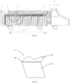
- FIG. 1 shows a schematic diagram of a refrigerated transport container 1 and a refrigerated transport vehicle according to an embodiment of this invention.
- the refrigerated transport container 1 according to an embodiment of this invention includes: a door body 2 disposed on a rear wall of the refrigerated transport container 1; an air duct 3 disposed on a top wall 11 of the refrigerated transport container 1 and extending in a direction towards or away from the door body 2 e.g.
- an air inlet 4 disposed at one end of the air duct 3 close to the door body 2 and configured to introduce cold air into the refrigerated transport container 1; and an air baffle unit 5 whose top portion is correspondingly disposed on one side of the air duct 3 close to the air inlet 4 and whose bottom portion can extend in a direction towards a bottom wall 12 of the refrigerated transport container 1 e.g. a direction close to a bottom wall 12 of the refrigerated transport container 1.
- the refrigerated transport container 1 may be a container or a container mounted on a logistics transport tool such as a vehicle or a ship, and there is no particular limitation on the container or container as long as it can form a structure in which conditioned air circulates. In most cases, the conditioned air is cold air. In less common cases, it is necessary to introduce hot air into the box, for example, in the case where the ambient temperature is too low. The embodiment disclosed herein only takes the introduction of cold air as an example.
- the door body 2 is disposed on the rear wall of the refrigerated transport container 1, and the rear wall is located at one end of the refrigerated transport container 1 in a length direction (Y-axis direction).
- the air duct 3 is disposed on the top wall 11 of the refrigerated transport container 1 and extends in a direction towards or away from the door body 2 (that is, a length direction of the refrigerated transport container 1; and/or a direction close to or away from the door body 2).
- the air duct 3 is used for conveying cold air into the refrigerated transport container 1.
- the air inlet 4 is disposed at one end of the air duct 3 close to the door body 2 and faces the door body 2, and is used for introducing cold air into the refrigerated transport container 1.
- the other end of the air duct 3 is connected to an air outlet of a refrigeration device 8.
- the top portion of the air baffle unit 5 is correspondingly disposed on one side of the air duct 3 close to the air inlet 4, and the bottom portion of the air baffle unit 5 extends in the direction towards the bottom wall 12 of the refrigerated transport container 1 e.g. a direction close to the bottom wall 12 of the refrigerated transport container 1.
- the air baffle unit 5 may guide an airflow direction of cold air blown out from the air inlet 4, so that the cold air first passes through goods located on a rear side of the air baffle unit 5 (that is, one side of the air baffle unit 5 close to the door 2) in a top-bottom airflow direction, falls to a position close to the bottom wall 12, and then blows towards goods located on a front side of the air baffle unit 5 (that is, one side of the air baffle unit 5 away from the door body 2) in a bottom-top airflow direction.
- the airflow direction is a bottom-top diagonal flow direction.
- a rising airflow direction of the hot air generated due to the heat release of the goods is from bottom to top. That is to say, by providing the air baffle unit 5, the airflow direction of the cold air supplied to the goods located on the front side of the air baffle unit 5 is consistent with the rising airflow direction of the hot air generated by releasing heat from the goods itself, so as to avoid the situation in the related art that the cold air supplied from top to bottom is counteracted by the rising hot air flow, thereby facilitating better cooling of the part of goods.
- the air flow is forced to obliquely pass through the goods located on the rear side of the air baffle unit 5, pass through the bottom portion of the air baffle unit 5, and obliquely pass through the goods located on the front side of the air baffle unit 5, so that the situation that the air "short-circuits" from the top portion of the goods and flows directly back to an air return port without passing through the goods is avoided.
- the air baffle unit 5 of the embodiment of this invention is simple in structure, convenient to mount and high in universality in the first aspect, and in the second aspect, the airflow direction of the supplied cold air is consistent with the rising direction of the hot air generated by the heat release of the goods, thereby improving the cooling effect on the goods, and in the third aspect, the cold air can be forced to substantially pass through all the goods, thereby keeping the goods in a relatively uniform low-temperature state.
- the top portion of the air baffle unit 5 is an air baffle plate 51 disposed around the air duct 3.
- a bottom portion of the air baffle unit 5 is a curtain 52.
- the curtain 52 may be coiled and stored at the top portion of the air baffle unit 5 and may be unfolded to extend toward the bottom wall 12 of the refrigerated transport container 1.
- the air baffle plate 51 may have a notch to be matched with the air duct 3, so that the air baffle plate 51 is disposed around the air duct 3 in a manner that the notch is attached to the air duct 3.
- the air baffle plate 51 may abut against the top wall 11 to prevent cold air from flowing to a gap between the top wall 11 and the air baffle plate 51, which is beneficial to optimize the airflow direction of the cold air in the refrigerated transport container 1.
- the curtain 52 may be unfolded and clamped in the middle of the goods to guide the airflow direction of the cold air blown out from the air inlet 4, so as to prevent the cold air from flowing to the gap between the air baffle plate 51 and the goods.
- the curtain 52 may be coiled and stored at the top portion of the air baffle unit 5 to allow the goods or personnel to enter and exit when loading and unloading the goods, or may be used when transporting goods with a low heat productivity.
- the air baffle unit 5 in the above-described embodiment can be coiled, and therefore, loading and unloading are not affected.
- the air baffle unit 5 has been described in the above-described embodiment by taking the air baffle plate 51 and the curtain 52 as an example, this invention is not limited thereto. Any air baffle plate 5 falls within the scope of this invention as long as it can guide the airflow direction of the cold air blown out from the air inlet 4, and make the airflow direction on the rear side of the air baffle plate 5 substantially fall from top to bottom and the airflow direction on the front side of the air baffle plate 5 substantially raise from bottom to top.
- a shape of the air baffle unit 5, an extension length of the air baffle unit 5 on a Z-axis, an angle between an extension direction of the air baffle unit 5 and the Z-axis, and the like may be selected according to actual conditions.
- the air baffle unit 5 is an air baffle plate disposed around the air duct 3, and the bottom portion of the air baffle plate abuts against goods to guide the airflow direction of the cold air blown out from the air inlet 4.
- closely packed goods can, to a certain extent, act like the curtain 52 mentioned above.
- the top portion of the air baffle unit 5 is an air baffle plate 51 disposed around the air duct 3 near the air inlet 4.
- the bottom portion of the air baffle unit 5 is a baffle plate, that is, a hard plate 53 that is rotatably connected to the top portion of the air baffle unit 5.
- the air baffle plate 51 and the hard plate 53 may be connected through a rotation shaft 54.
- the air baffle plate 5 in the above-described embodiment can be turned over, and therefore, loading and unloading are not affected.
- the air duct 3 on the rear side of the air baffle unit 5 is provided with an openable and closable air port 31, and the air port 31 may be opened or closed according to actual requirements.
- opening and closing of the air port 31 are implemented by using a hook-and-loop fastener.
- the air baffle unit 5 is detachably connected to the air duct 3 or the top wall 11 or a side wall of the refrigerated transport container 1. Since the air baffle unit 5 is detachable, the air baffle unit 5 can be mounted or detached according to actual requirements, or a mounting position of the air baffle unit 5 can be properly adjusted.
- the adjustable position of the air baffle unit 5 generally ranges from a position near the air inlet 4 to a position at 1/2 the length of the refrigerated transport container.
- the air baffle unit 5 can be detachably connected to the air duct 3, the top wall 11 or the side wall by buckles, hooks, or the like.
- the air baffle unit 5 is slidably connected to the air duct 3 or the top wall 11 or the side wall of the refrigerated transport container 1.
- the air baffle unit 5 may be slidably connected to the top wall 11 by a pulley and a sliding groove, so as to adjust the mounting position of the air baffle unit 5.
- the refrigerated transport container 1 further includes a loading surface 7 that allows gas to pass therethrough.
- the loading surface 7 is spaced apart from and parallel to the bottom wall 12 of the refrigerated transport container 1. After the cold air blown from the air inlet 4 passes through the goods located on the rear side of the air baffle unit 5 in the top-bottom airflow direction and falls to the position close to the bottom wall 12, a part of the cold air flows forward through an air channel between the loading surface 7 and the bottom wall 12, and then passes through the loading surface 7 in the bottom-top airflow direction and blows towards the goods located on the front side of the air baffle unit 5.
- the loading surface 7 may include structures such as a porous loading bearing plate, a porous loading bearing net, and a long strip channel steel.
- the refrigerated transport container 1 includes a first air return port 91.
- the first air return port 91 is disposed on a front wall of the refrigerated transport container 1 opposite to the door body 2, and disposed adjacent to the top wall 11 or adjacent to the air duct 3 in terms of height in a vertical direction (Z-axis direction).
- the first air return port 91 is used for allowing air to flow out of the refrigerated transport container 1 and return to the refrigeration device 8.
- the front wall includes a partition plate 9 disposed facing an air intake port of the refrigeration device 8, and a top end of the partition plate 9 and the air duct 3 define the first air return port 91.
- the air in the refrigerated transport container 1 flows into the air intake port of the refrigeration device 8 after passing through the first air return port 91.
- FIG. 7 corresponds to the case of transporting goods with low heat release characteristics (for example, vegetables and medicines).
- a plurality of air ports 31 on the air duct 3 are opened, the first air return port 91 adjacent to the top wall 11 is closed, and the second air return port 92 adjacent to the bottom wall 12 is opened.
- the cold air is fed into the air duct 3 through the air outlet of the refrigeration device 8, and the cold air in the air duct 3 is blown out from the plurality of air ports 31 on the air duct 3 and the air inlet 4 at an end portion of the air duct 3 and is blown towards the goods in the top-bottom airflow direction.
- cold air is introduced into the refrigerated transport container through an air inlet at one end of an air duct close to a door body and small openings on the air duct (i.e., in the manner shown in FIG. 7 ), and an air return port that allows the air to flow out of the refrigerated transport container is disposed at a position of a front portion (i.e., one side opposite to the door body) of the refrigerated transport container, which is adjacent to the bottom wall, that is, the air return port is disposed at a diagonal position relative to the air inlet of the air duct.
- a larger area has a temperature of 31.9°C or higher, and the highest temperature in an area reaches 48.4°C.
- most areas have a temperature of 22.4°C or lower, and only a small part of the areas have a slightly higher temperature, which is about 34.2°C to 41.3°C. That is, when the refrigerated transport container actually transports goods with high heat release characteristics, the goods can reach a more uniform low-temperature state using the refrigerated transport container 1 in the embodiment as compared with the traditional mode according to the comparative example.
Landscapes
- Engineering & Computer Science (AREA)
- Mechanical Engineering (AREA)
- Physics & Mathematics (AREA)
- Thermal Sciences (AREA)
- Chemical & Material Sciences (AREA)
- Combustion & Propulsion (AREA)
- General Engineering & Computer Science (AREA)
- Health & Medical Sciences (AREA)
- Public Health (AREA)
- Transportation (AREA)
- Devices That Are Associated With Refrigeration Equipment (AREA)
Abstract
This invention provides a refrigerated transport container (1) and a refrigerated transport vehicle. The refrigerated transport container (1) includes: a door body (2) disposed on a rear wall of the refrigerated transport container (1); an air duct (3) disposed on a top wall (11) of the refrigerated transport container (1) and extending in a direction towards or away from the door body (2) e.g. a direction close to or away from the door body (2); an air inlet (4) disposed at one end of the air duct (3) close to the door body (2) and configured to introduce conditioned air into the refrigerated transport container (1); and an air baffle unit (5) whose top portion is correspondingly disposed on one side of the air duct (3) close to the air inlet (4) and whose bottom portion can extend in a direction towards a bottom wall (12) of the refrigerated transport container (1) e.g. a direction close to a bottom wall (12) of the refrigerated transport container (1) .
Description
- This invention relates to the field of refrigerated transport technique, and in particular to a refrigerated transport container and a refrigerated transport vehicle.
- A refrigerated transport container can provide cold air for goods in the refrigerated transport container, so that the goods are kept at a lower-temperature state. However, in the related art, when a refrigerated transport container transports goods with high heat release characteristics, it is difficult to keep the goods at a low-temperature state.
- Embodiments of the invention aim to provide a refrigerated transport container and a refrigerated transport vehicle, so as to at least solve or alleviate some problems existing in the related art.
- According to a first aspect of the invention there is provided a refrigerated transport container including: a door body disposed on a rear wall of the refrigerated transport container; an air duct disposed on a top wall of the refrigerated transport container and extending in a direction towards or away from the door body; an air inlet disposed at one end of the air duct close to the door body and configured to introduce conditioned air into the refrigerated transport container; and an air baffle unit whose top portion is correspondingly disposed on one side of the air duct close to the air inlet and whose bottom portion is extendable in a direction towards a bottom wall of the refrigerated transport container.
- Optionally, the direction towards or away from the door body is a direction close to or away from the door body.
- Optionally, the direction towards the bottom wall is a direction close to the bottom wall.
- Optionally, the top portion of the air baffle unit is an air baffle plate disposed around the air duct near the air inlet.
- Optionally, the bottom portion of the air baffle unit is a curtain.
- Optionally, the curtain may be coiled and stored at the top portion of the air baffle unit, and may be unfolded to extend toward the bottom wall of the refrigerated transport container.
- Optionally, the air baffle unit is detachably connected to the air duct or the top wall or a side wall of the refrigerated transport container.
- Optionally, the bottom portion of the air baffle unit is a baffle plate rotatably connected to the top portion of the air baffle unit.
- Optionally, the top portion of the air baffle unit abuts against the top wall.
- Optionally, the refrigerated transport container further includes a loading surface that allows gas to pass therethrough. Optionally, the loading surface is spaced apart from and parallel to the bottom wall of the refrigerated transport container.
- Optionally, the refrigerated transport container further includes a first air return port. Optionally, the first air return port is disposed on a front wall of the refrigerated transport container opposite to the door body and is disposed adjacent to the top wall in terms of height in a vertical direction, and the first air return port is configured to allow air to flow out of the refrigerated transport container.
- Optionally, the refrigerated transport container further includes a second air return port and an air return port switching device. Optionally, the second air return port is disposed on the front wall of the refrigerated transport container opposite to the door body, and is disposed adjacent to the bottom wall in terms of height in the vertical direction, and the air return port switching device is configured to alternatively open the first air return port or the second air return port.
- According to a second aspect of the invention there is provided a refrigerated transport vehicle equipped with the refrigerated transport container according to the first aspect of the invention.
- The refrigerated transport container and the refrigerated transport vehicle according to this invention can keep goods in a low-temperature state when the refrigerated transport container transports goods with high heat release characteristics.
- Certain exemplary embodiments will now be described in greater detail by way of example only and with reference to the accompanying drawings in which:
-
FIG. 1 is a schematic structural diagram showing a refrigerated transport container and a refrigerated transport vehicle, and a schematic diagram of a cold air flow direction in the refrigerated transport container when transporting goods with high heat release characteristics; -
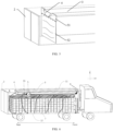
FIG. 2 is a schematic diagram showing a curtain in a refrigerated transport container in a coiled and stored state; -
FIG. 3 is a schematic structural diagram showing a refrigerated transport container and a refrigerated transport vehicle, and a schematic diagram of a cold air flow direction in the refrigerated transport container when transporting goods with high heat release characteristics; -
FIG. 4 is a schematic structural diagram showing an air baffle unit including a baffle plate (hard plate); -
FIG. 5 is a schematic structural diagram showing an air baffle unit including a curtain; -
FIG. 6 is a schematic structural diagram showing a refrigerated transport container and a refrigerated transport vehicle, and a schematic diagram of a cold air flow direction in the refrigerated transport container when transporting goods with high heat release characteristics; -
FIG. 7 is a schematic structural diagram showing a refrigerated transport container and a refrigerated transport vehicle, and a schematic diagram of a cold air flow direction in the refrigerated transport container when transporting goods with low heat release characteristics; -
FIG. 8 is a schematic structural diagram showing a partition plate, a rotation switching member, and a sliding switching member; -
FIG. 9 is a schematic diagram showing states of the partition plate, the rotation switching member, and the sliding switching member in the refrigerated transport container when a first air return port is closed and a second air return port is opened; -
FIG. 10 is a schematic diagram showing states of the partition plate, the rotation switching member, and the sliding switching member in the refrigerated transport container when the second air return port is closed and the first air return port is opened; and -
FIG. 11 shows a computer simulation temperature cloud diagram of a refrigerated transport container and a refrigerated transport container according to a comparative example (the refrigerated transport container in the comparative example adopts a traditional mode in which air is supplied from an upper portion and the air returns to a lower portion) when the two transport goods with high heat release characteristics. - Reference Signs List: 1: refrigerated transport container, 11: top wall, 12: bottom wall, 2: door body; 3: air duct; 4: air inlet, 5: air baffle unit, 51: air baffle plate, 52: curtain, 53: hard plate, 54: rotation shaft, 7: loading surface, 8: refrigeration device, 9: partition plate, 91: first air return port, 92: second air return port, 92a: air hole, 31: air port, 6: air return port switching device, 61: rotation switching member, 62: sliding switching member.
- First, it should be noted that the composition, working principle, characteristics, advantages and the like of a refrigerated transport container and a refrigerated transport vehicle according to this invention will be described below by way of example, but it should be understood that all descriptions are given for illustrative purposes only, and therefore should not be construed as any limitation to this invention.
- In addition, for any single technical feature described or implied in the embodiments mentioned herein, or any single technical feature shown or implied in each figure, this invention still allows any combination or deletion between these technical features (or equivalents thereof) without any technical obstacle, thereby obtaining more other embodiments of this invention that may not be directly mentioned herein.
-
FIG. 1 shows a schematic diagram of a refrigeratedtransport container 1 and a refrigerated transport vehicle according to an embodiment of this invention. The refrigeratedtransport container 1 according to an embodiment of this invention includes: adoor body 2 disposed on a rear wall of the refrigeratedtransport container 1; anair duct 3 disposed on atop wall 11 of the refrigeratedtransport container 1 and extending in a direction towards or away from thedoor body 2 e.g. a direction close to or away from thedoor body 2; anair inlet 4 disposed at one end of theair duct 3 close to thedoor body 2 and configured to introduce cold air into the refrigeratedtransport container 1; and anair baffle unit 5 whose top portion is correspondingly disposed on one side of theair duct 3 close to theair inlet 4 and whose bottom portion can extend in a direction towards abottom wall 12 of the refrigeratedtransport container 1 e.g. a direction close to abottom wall 12 of the refrigeratedtransport container 1. - Specifically, the refrigerated
transport container 1 may be a container or a container mounted on a logistics transport tool such as a vehicle or a ship, and there is no particular limitation on the container or container as long as it can form a structure in which conditioned air circulates. In most cases, the conditioned air is cold air. In less common cases, it is necessary to introduce hot air into the box, for example, in the case where the ambient temperature is too low. The embodiment disclosed herein only takes the introduction of cold air as an example. Thedoor body 2 is disposed on the rear wall of the refrigeratedtransport container 1, and the rear wall is located at one end of the refrigeratedtransport container 1 in a length direction (Y-axis direction). When thedoor body 2 is opened, goods may be carried into the refrigeratedtransport container 1 through thedoor body 2. Theair duct 3 is disposed on thetop wall 11 of the refrigeratedtransport container 1 and extends in a direction towards or away from the door body 2 (that is, a length direction of the refrigeratedtransport container 1; and/or a direction close to or away from the door body 2). Theair duct 3 is used for conveying cold air into the refrigeratedtransport container 1. Theair inlet 4 is disposed at one end of theair duct 3 close to thedoor body 2 and faces thedoor body 2, and is used for introducing cold air into the refrigeratedtransport container 1. The other end of theair duct 3 is connected to an air outlet of arefrigeration device 8. - The top portion of the
air baffle unit 5 is correspondingly disposed on one side of theair duct 3 close to theair inlet 4, and the bottom portion of theair baffle unit 5 extends in the direction towards thebottom wall 12 of the refrigeratedtransport container 1 e.g. a direction close to thebottom wall 12 of the refrigeratedtransport container 1. Theair baffle unit 5 may guide an airflow direction of cold air blown out from theair inlet 4, so that the cold air first passes through goods located on a rear side of the air baffle unit 5 (that is, one side of theair baffle unit 5 close to the door 2) in a top-bottom airflow direction, falls to a position close to thebottom wall 12, and then blows towards goods located on a front side of the air baffle unit 5 (that is, one side of theair baffle unit 5 away from the door body 2) in a bottom-top airflow direction. Thus, for the goods located on the front side of theair baffle unit 5, the airflow direction is a bottom-top diagonal flow direction. When the goods have high heat release characteristics, a rising airflow direction of the hot air generated due to the heat release of the goods is from bottom to top. That is to say, by providing theair baffle unit 5, the airflow direction of the cold air supplied to the goods located on the front side of theair baffle unit 5 is consistent with the rising airflow direction of the hot air generated by releasing heat from the goods itself, so as to avoid the situation in the related art that the cold air supplied from top to bottom is counteracted by the rising hot air flow, thereby facilitating better cooling of the part of goods. Meanwhile, for the goods located on the rear side of theair baffle unit 5, although the supplied cold air and the rising hot air are counteracted, a relatively good cooling effect on the goods in this area is obtained because the cold air is just conveyed out of the air duct and has a relatively low temperature and a very large speed (far larger than that of the rising airflow speed), and the airflow direction is a top-bottom diagonal flow direction. In addition, by providing theair baffle unit 5, the air flow is forced to obliquely pass through the goods located on the rear side of theair baffle unit 5, pass through the bottom portion of theair baffle unit 5, and obliquely pass through the goods located on the front side of theair baffle unit 5, so that the situation that the air "short-circuits" from the top portion of the goods and flows directly back to an air return port without passing through the goods is avoided. It can be seen that, according to theair baffle unit 5 of the embodiment of this invention, theair baffle unit 5 is simple in structure, convenient to mount and high in universality in the first aspect, and in the second aspect, the airflow direction of the supplied cold air is consistent with the rising direction of the hot air generated by the heat release of the goods, thereby improving the cooling effect on the goods, and in the third aspect, the cold air can be forced to substantially pass through all the goods, thereby keeping the goods in a relatively uniform low-temperature state. - In some embodiments, as shown in
FIG. 1, FIG. 2 , andFIG. 5 , the top portion of theair baffle unit 5 is anair baffle plate 51 disposed around theair duct 3. A bottom portion of theair baffle unit 5 is acurtain 52. Thecurtain 52 may be coiled and stored at the top portion of theair baffle unit 5 and may be unfolded to extend toward thebottom wall 12 of the refrigeratedtransport container 1. Theair baffle plate 51 may have a notch to be matched with theair duct 3, so that theair baffle plate 51 is disposed around theair duct 3 in a manner that the notch is attached to theair duct 3. In addition, theair baffle plate 51 may abut against thetop wall 11 to prevent cold air from flowing to a gap between thetop wall 11 and theair baffle plate 51, which is beneficial to optimize the airflow direction of the cold air in therefrigerated transport container 1. Thecurtain 52 may be unfolded and clamped in the middle of the goods to guide the airflow direction of the cold air blown out from theair inlet 4, so as to prevent the cold air from flowing to the gap between theair baffle plate 51 and the goods. Thecurtain 52 may be coiled and stored at the top portion of theair baffle unit 5 to allow the goods or personnel to enter and exit when loading and unloading the goods, or may be used when transporting goods with a low heat productivity. In other words, theair baffle unit 5 in the above-described embodiment can be coiled, and therefore, loading and unloading are not affected. - Although the
air baffle unit 5 has been described in the above-described embodiment by taking theair baffle plate 51 and thecurtain 52 as an example, this invention is not limited thereto. Anyair baffle plate 5 falls within the scope of this invention as long as it can guide the airflow direction of the cold air blown out from theair inlet 4, and make the airflow direction on the rear side of theair baffle plate 5 substantially fall from top to bottom and the airflow direction on the front side of theair baffle plate 5 substantially raise from bottom to top. In an alternative embodiment, a shape of theair baffle unit 5, an extension length of theair baffle unit 5 on a Z-axis, an angle between an extension direction of theair baffle unit 5 and the Z-axis, and the like may be selected according to actual conditions. - In some embodiments, as shown in
FIG. 3 , theair baffle unit 5 is an air baffle plate disposed around theair duct 3, and the bottom portion of the air baffle plate abuts against goods to guide the airflow direction of the cold air blown out from theair inlet 4. In the embodiment shown inFIG. 3 , closely packed goods can, to a certain extent, act like thecurtain 52 mentioned above. - In some embodiments, as shown in
FIG. 4 , the top portion of theair baffle unit 5 is anair baffle plate 51 disposed around theair duct 3 near theair inlet 4. The bottom portion of theair baffle unit 5 is a baffle plate, that is, ahard plate 53 that is rotatably connected to the top portion of theair baffle unit 5. Theair baffle plate 51 and thehard plate 53 may be connected through arotation shaft 54. Theair baffle plate 5 in the above-described embodiment can be turned over, and therefore, loading and unloading are not affected. - In some embodiments, as shown in
FIG. 6 , theair duct 3 on the rear side of theair baffle unit 5 is provided with an openable andclosable air port 31, and theair port 31 may be opened or closed according to actual requirements. In a specific embodiment, opening and closing of theair port 31 are implemented by using a hook-and-loop fastener. - In some embodiments, the
air baffle unit 5 is detachably connected to theair duct 3 or thetop wall 11 or a side wall of therefrigerated transport container 1. Since theair baffle unit 5 is detachable, theair baffle unit 5 can be mounted or detached according to actual requirements, or a mounting position of theair baffle unit 5 can be properly adjusted. The adjustable position of theair baffle unit 5 generally ranges from a position near theair inlet 4 to a position at 1/2 the length of the refrigerated transport container. Theair baffle unit 5 can be detachably connected to theair duct 3, thetop wall 11 or the side wall by buckles, hooks, or the like. In some embodiments, theair baffle unit 5 is slidably connected to theair duct 3 or thetop wall 11 or the side wall of therefrigerated transport container 1. For example, theair baffle unit 5 may be slidably connected to thetop wall 11 by a pulley and a sliding groove, so as to adjust the mounting position of theair baffle unit 5. - In some embodiments, the
refrigerated transport container 1 further includes aloading surface 7 that allows gas to pass therethrough. Theloading surface 7 is spaced apart from and parallel to thebottom wall 12 of therefrigerated transport container 1. After the cold air blown from theair inlet 4 passes through the goods located on the rear side of theair baffle unit 5 in the top-bottom airflow direction and falls to the position close to thebottom wall 12, a part of the cold air flows forward through an air channel between theloading surface 7 and thebottom wall 12, and then passes through theloading surface 7 in the bottom-top airflow direction and blows towards the goods located on the front side of theair baffle unit 5. Specifically, theloading surface 7 may include structures such as a porous loading bearing plate, a porous loading bearing net, and a long strip channel steel. - In some embodiments, as shown in
FIG. 1 , therefrigerated transport container 1 includes a firstair return port 91. The firstair return port 91 is disposed on a front wall of therefrigerated transport container 1 opposite to thedoor body 2, and disposed adjacent to thetop wall 11 or adjacent to theair duct 3 in terms of height in a vertical direction (Z-axis direction). The firstair return port 91 is used for allowing air to flow out of therefrigerated transport container 1 and return to therefrigeration device 8. By disposing the firstair return port 91 adjacent to theair duct 3, air passing through the goods in the bottom-top airflow direction can flow out of therefrigerated transport container 1 in a more suitable path, and a favorable diagonal flowing cold air flow is formed in the space on the front side of theair baffle unit 5. In the illustrated embodiment, the front wall includes apartition plate 9 disposed facing an air intake port of therefrigeration device 8, and a top end of thepartition plate 9 and theair duct 3 define the firstair return port 91. The air in therefrigerated transport container 1 flows into the air intake port of therefrigeration device 8 after passing through the firstair return port 91. - In some embodiments, as shown in
FIG. 1 ,FIG. 7 and FIG. 8 , therefrigerated transport container 1 includes the firstair return port 91, a secondair return port 92, and an air returnport switching device 6. The firstair return port 91 is disposed on the front wall of therefrigerated transport container 1 opposite to thedoor body 2, and disposed adjacent to thetop wall 11 or adjacent to theair duct 3 in terms of height in the vertical direction. The secondair return port 92 is disposed on the front wall of therefrigerated transport container 1 opposite to thedoor body 2, and disposed adjacent to thebottom wall 12 in terms of height in the vertical direction. The air returnport switching device 6 can alternatively open the firstair return port 91 or the secondair return port 92. In the illustrated embodiment, the front wall includes thepartition plate 9 disposed facing the air intake port of therefrigeration device 8. The top end of thepartition plate 9 and theair duct 3 define the firstair return port 91, a bottom end of thepartition plate 9 and thebottom wall 12 define a part of the secondair return port 92, andair holes 92a at the bottom portion of thepartition plate 9 forms another part of the secondair return port 92. When the firstair return port 91 is opened, the secondair return port 92 is closed, so that the air in therefrigerated transport container 1 flows into the air intake port of therefrigeration device 8 through the firstair return port 91. When the secondair return port 92 is opened, the firstair return port 91 is closed, so that the air in therefrigerated transport container 1 flows into the air intake port of therefrigeration device 8 through the secondair return port 92. In a specific embodiment, as shown inFIG. 8 to FIG. 10 , the air returnport switching device 6 includes arotation switching member 61 rotatably connected to the top end of thepartition plate 9, and a sliding switchingmember 62 slidably connected to the bottom end of thepartition plate 9. Therotation switching member 61 may rotate to abut against therefrigeration device 8, or may be mounted on an outer wall of therefrigeration device 8 to close the firstair return port 91. The sliding switchingmember 62 may slide between the bottom end of thepartition plate 9 and thebottom wall 12 to close the secondair return port 92. It should be noted that thepartition plate 9, therotation switching member 61, and the sliding switchingmember 62 herein are only one embodiment, and any switching measure is within the scope of this invention as long as it can achieve the purpose of switching between the two air return ports. - With continued reference to
FIG. 1 andFIG. 7 ,FIG. 1 andFIG. 7 show similar structures ofrefrigerated transport containers 1. That is, each includes theair duct 3 disposed on thetop wall 11, and one end of theair duct 3 is used for connecting an air outlet of therefrigeration device 8. However, as shown by arrows indicating airflow directions inFIG. 1 andFIG. 7 , therefrigerated transport containers 1 inFIG. 1 andFIG. 7 provide two different airflow modes, and the two different airflow modes may respectively correspond to the case of transporting goods with high heat release characteristics and the case of transporting goods with low heat release characteristics. - Referring to
FIG. 7, FIG. 7 corresponds to the case of transporting goods with low heat release characteristics (for example, vegetables and medicines). In this case, a plurality ofair ports 31 on theair duct 3 are opened, the firstair return port 91 adjacent to thetop wall 11 is closed, and the secondair return port 92 adjacent to thebottom wall 12 is opened. The cold air is fed into theair duct 3 through the air outlet of therefrigeration device 8, and the cold air in theair duct 3 is blown out from the plurality ofair ports 31 on theair duct 3 and theair inlet 4 at an end portion of theair duct 3 and is blown towards the goods in the top-bottom airflow direction. The buoyancy of the hot air generated by the goods with a low heat productivity is very small, and therefore, the supplied cold air naturally falls through the goods, so that the goods are kept in a low-temperature state, and then the air in therefrigerated transport container 1 flows into the air intake port of therefrigeration device 8 after passing through the secondair return port 92. It should be noted that, inFIG. 7 , the cold air basically flows from top to bottom, and therefore, the rolling of thecurtain 52 of theair baffle unit 5 will not have much influence on the descending of the cold air. Of course, if transportation of goods with a high heat productivity is not required for a long time, theair baffle unit 5 may also be detached. - Referring to
FIG. 1, FIG. 1 corresponds to the case of transporting goods with high heat release characteristics (for example, durians). In this case, the plurality ofair ports 31 on theair duct 3 are closed, the secondair return port 92 adjacent to thebottom wall 12 is closed, and the firstair return port 91 adjacent to thetop wall 11 is opened. The cold air is fed into theair duct 3 through the air outlet of therefrigeration device 8. The cold air in theair duct 3 is blown out from theair inlet 4 at the end portion of theair duct 3, first passes through the goods located on the rear side of theair baffle unit 5 in the top-bottom airflow direction and falls to the position close to the bottom wall, and then is blown towards the goods located on the front side of theair baffle unit 5 in the bottom-top airflow direction. Finally, the air in therefrigerated transport container 1 flows into the air intake port of therefrigeration device 8 after passing through the firstair return port 91. -
FIG. 11 shows a computer simulation temperature cloud diagram of a refrigerated transport container according to an embodiment and a refrigerated transport container according to a comparative example (that is, a traditional refrigerated transport container supplied with wind from top to bottom) when the two transport goods with high heat release characteristics. - As shown in
FIG. 1 , cold air is introduced into therefrigerated transport container 1 through theair inlet 4 at one end of theair duct 3 close to thedoor body 2, the air return port that allows the air to flow out of therefrigerated transport container 1 is disposed at a position of the front portion (i.e., one side opposite to the door body 2) of therefrigerated transport container 1, which is adjacent to thetop wall 11, and theair baffle unit 5 is disposed on one side of theair duct 3 close to theair inlet 4. - In the refrigerated transport container according to the comparative example, cold air is introduced into the refrigerated transport container through an air inlet at one end of an air duct close to a door body and small openings on the air duct (i.e., in the manner shown in
FIG. 7 ), and an air return port that allows the air to flow out of the refrigerated transport container is disposed at a position of a front portion (i.e., one side opposite to the door body) of the refrigerated transport container, which is adjacent to the bottom wall, that is, the air return port is disposed at a diagonal position relative to the air inlet of the air duct. - As shown in
FIG. 11 , in the refrigerated transport container in the comparative example, a larger area has a temperature of 31.9°C or higher, and the highest temperature in an area reaches 48.4°C. However, in therefrigerated transport container 1 in the embodiment, most areas have a temperature of 22.4°C or lower, and only a small part of the areas have a slightly higher temperature, which is about 34.2°C to 41.3°C. That is, when the refrigerated transport container actually transports goods with high heat release characteristics, the goods can reach a more uniform low-temperature state using therefrigerated transport container 1 in the embodiment as compared with the traditional mode according to the comparative example. - The above are only preferred embodiments of this invention and are not intended to limit this invention, and many modifications, equivalent substitutions, and improvements shall fall within the protection scope of this invention, which is as defined by the appended claims.
Claims (11)
- A refrigerated transport container (1), comprising:a door body (2) disposed on a rear wall of the refrigerated transport container;an air duct (3) disposed on a top wall (11) of the refrigerated transport container and extending in a direction towards or away from the door body;an air inlet (4) disposed at one end of the air duct close to the door body and configured to introduce conditioned air into the refrigerated transport container; andan air baffle unit (5) whose top portion is correspondingly disposed on one side of the air duct close to the air inlet and whose bottom portion is extendable in a direction towards a bottom wall (12) of the refrigerated transport container.
- The refrigerated transport container (1) according to claim 1, wherein the top portion of the air baffle unit (5) is an air baffle plate (51) disposed around the air duct (3) near the air inlet (4).
- The refrigerated transport container (1) according to claim 1 or 2, wherein the bottom portion of the air baffle unit (5) is a curtain (52).
- The refrigerated transport container (1) according to claim 3, wherein the curtain (52) is coiled and stored at the top portion of the air baffle unit (5), and is configured to be unfolded to extend toward the bottom wall (12) of the refrigerated transport container.
- The refrigerated transport container (1) according to claim 1 or 2, wherein the bottom portion of the air baffle unit (5) is a baffle plate (53) rotatably connected to the top portion of the air baffle unit.
- The refrigerated transport container (1) according to any preceding claim, wherein the air baffle unit (5) is fixedly and detachably connected to the air duct (3) or the top wall (11) or a side wall of the refrigerated transport container.
- The refrigerated transport container (1) according to any preceding claim, wherein the top portion of the air baffle unit (5) abuts against the top wall (11).
- The refrigerated transport container (1) according to any preceding claim, further comprising a loading surface (7) that allows gas to pass therethrough, wherein the loading surface is spaced apart from and parallel to the bottom wall (12) of the refrigerated transport container.
- The refrigerated transport container (1) according to any preceding claim, further comprising a first air return port (91), wherein the first air return port is disposed on a front wall of the refrigerated transport container opposite to the door body (2) and is disposed adjacent to the top wall (11) in terms of height in a vertical direction, and the first air return port is configured to allow air to flow out of the refrigerated transport container.
- The refrigerated transport container (1) according to claim 9, further comprising a second air return port (92) and an air return port switching device (6), wherein the second air return port is disposed on the front wall of the refrigerated transport container opposite to the door body (2), and is disposed adjacent to the bottom wall (12) in terms of height in the vertical direction, and the air return port switching device is configured to alternatively open the first air return port or the second air return port.
- A refrigerated transport vehicle equipped with the refrigerated transport container (1) according to any one of claims 1 to 10.
Applications Claiming Priority (1)
| Application Number | Priority Date | Filing Date | Title |
|---|---|---|---|
| CN202311144427.4A CN119567790A (en) | 2023-09-05 | 2023-09-05 | Refrigerated transport case and refrigerated transport vehicle |
Publications (1)
| Publication Number | Publication Date |
|---|---|
| EP4523964A1 true EP4523964A1 (en) | 2025-03-19 |
Family
ID=92708880
Family Applications (1)
| Application Number | Title | Priority Date | Filing Date |
|---|---|---|---|
| EP24198726.2A Pending EP4523964A1 (en) | 2023-09-05 | 2024-09-05 | Refrigerated transport container and refrigerated transport vehicle |
Country Status (3)
| Country | Link |
|---|---|
| US (1) | US20250075961A1 (en) |
| EP (1) | EP4523964A1 (en) |
| CN (1) | CN119567790A (en) |
Families Citing this family (2)
| Publication number | Priority date | Publication date | Assignee | Title |
|---|---|---|---|---|
| WO2025251156A1 (en) * | 2024-06-06 | 2025-12-11 | Remorques Cft Inc. | Trailer with modular climate conditioned zones |
| CN120793389B (en) * | 2025-09-15 | 2025-12-02 | 成都纺织高等专科学校 | Artificial Intelligence-Based Control Method and Device for Refrigerated Containers |
Citations (4)
| Publication number | Priority date | Publication date | Assignee | Title |
|---|---|---|---|---|
| US2534272A (en) * | 1947-12-22 | 1950-12-19 | Dole Refrigerating Co | Multitemperature refrigerator car |
| JPH11201618A (en) * | 1998-01-13 | 1999-07-30 | Shinbutsuryuu System Kaihatsu Kyodo Kumiai | Air call duct device for refrigerated and refrigerated vehicles |
| JP3212953B2 (en) * | 1994-06-24 | 2001-09-25 | クールパックシステム株式会社 | Liquefied gas supply system for low temperature preservation goods transportation and delivery vehicles |
| CN109515293A (en) * | 2018-11-28 | 2019-03-26 | 合肥森隆专用汽车有限公司 | A kind of classified storage type energy-saving cold storage vehicle |
-
2023
- 2023-09-05 CN CN202311144427.4A patent/CN119567790A/en active Pending
-
2024
- 2024-08-29 US US18/819,144 patent/US20250075961A1/en active Pending
- 2024-09-05 EP EP24198726.2A patent/EP4523964A1/en active Pending
Patent Citations (4)
| Publication number | Priority date | Publication date | Assignee | Title |
|---|---|---|---|---|
| US2534272A (en) * | 1947-12-22 | 1950-12-19 | Dole Refrigerating Co | Multitemperature refrigerator car |
| JP3212953B2 (en) * | 1994-06-24 | 2001-09-25 | クールパックシステム株式会社 | Liquefied gas supply system for low temperature preservation goods transportation and delivery vehicles |
| JPH11201618A (en) * | 1998-01-13 | 1999-07-30 | Shinbutsuryuu System Kaihatsu Kyodo Kumiai | Air call duct device for refrigerated and refrigerated vehicles |
| CN109515293A (en) * | 2018-11-28 | 2019-03-26 | 合肥森隆专用汽车有限公司 | A kind of classified storage type energy-saving cold storage vehicle |
Also Published As
| Publication number | Publication date |
|---|---|
| CN119567790A (en) | 2025-03-07 |
| US20250075961A1 (en) | 2025-03-06 |
Similar Documents
| Publication | Publication Date | Title |
|---|---|---|
| EP4523964A1 (en) | Refrigerated transport container and refrigerated transport vehicle | |
| JP5477039B2 (en) | Open showcase product display shelf | |
| CN107062750A (en) | A kind of wind cooling refrigerator and its control method | |
| EP2394111B1 (en) | Temperature distribution improvement in refrigerated container | |
| CN113375395A (en) | Refrigerator with duct system to supply cold air from freezing evaporator to ice maker | |
| EP2517909B1 (en) | An air curtain, and a vehicle provided with such an air curtain | |
| CN210107860U (en) | Temperature control device of refrigerator car | |
| JP2015052441A (en) | Frozen car | |
| CN112956872A (en) | Showcase | |
| CN220639444U (en) | Refrigerated transport case and refrigerated transport vehicle | |
| US20200318424A1 (en) | Curtain and refrigerated unit for transportation, refrigerated vehicle | |
| CN105593620B (en) | Kick plate for reefer container assembly | |
| CN111907394A (en) | Airflow diversion system for refrigeration compartment, refrigeration compartment and refrigeration truck | |
| CN220442351U (en) | Refrigeration showcase | |
| JPH0754788Y2 (en) | Packing box for frozen transportation of flowers etc. | |
| JP2008185241A (en) | Multi-room cold car | |
| JP2003314938A (en) | Delivery car | |
| CN216231590U (en) | A cold chain logistics temperature adjustment equipment | |
| CN213781081U (en) | Automatic vending machine with heating cabinet | |
| JP6357889B2 (en) | Refrigerated warehouse | |
| JP3016556U (en) | Cold storage car | |
| US20090049851A1 (en) | Transport refrigeration damper assembly | |
| JP7129925B2 (en) | refrigerator | |
| JP2519406Y2 (en) | Freezer freight refrigeration ship | |
| CN107192210A (en) | Refrigerator and its drawer |
Legal Events
| Date | Code | Title | Description |
|---|---|---|---|
| PUAI | Public reference made under article 153(3) epc to a published international application that has entered the european phase |
Free format text: ORIGINAL CODE: 0009012 |
|
| STAA | Information on the status of an ep patent application or granted ep patent |
Free format text: STATUS: THE APPLICATION HAS BEEN PUBLISHED |
|
| AK | Designated contracting states |
Kind code of ref document: A1 Designated state(s): AL AT BE BG CH CY CZ DE DK EE ES FI FR GB GR HR HU IE IS IT LI LT LU LV MC ME MK MT NL NO PL PT RO RS SE SI SK SM TR |
|
| STAA | Information on the status of an ep patent application or granted ep patent |
Free format text: STATUS: REQUEST FOR EXAMINATION WAS MADE |
|
| 17P | Request for examination filed |
Effective date: 20250522 |