EP4523941A1 - Driver monitoring system - Google Patents
Driver monitoring system Download PDFInfo
- Publication number
- EP4523941A1 EP4523941A1 EP24195826.3A EP24195826A EP4523941A1 EP 4523941 A1 EP4523941 A1 EP 4523941A1 EP 24195826 A EP24195826 A EP 24195826A EP 4523941 A1 EP4523941 A1 EP 4523941A1
- Authority
- EP
- European Patent Office
- Prior art keywords
- driver
- seat side
- transmitter
- onboard device
- disposed
- Prior art date
- Legal status (The legal status is an assumption and is not a legal conclusion. Google has not performed a legal analysis and makes no representation as to the accuracy of the status listed.)
- Granted
Links
Images




Classifications
-
- G—PHYSICS
- G06—COMPUTING OR CALCULATING; COUNTING
- G06V—IMAGE OR VIDEO RECOGNITION OR UNDERSTANDING
- G06V20/00—Scenes; Scene-specific elements
- G06V20/50—Context or environment of the image
- G06V20/59—Context or environment of the image inside of a vehicle, e.g. relating to seat occupancy, driver state or inner lighting conditions
- G06V20/597—Recognising the driver's state or behaviour, e.g. attention or drowsiness
-
- B—PERFORMING OPERATIONS; TRANSPORTING
- B60—VEHICLES IN GENERAL
- B60K—ARRANGEMENT OR MOUNTING OF PROPULSION UNITS OR OF TRANSMISSIONS IN VEHICLES; ARRANGEMENT OR MOUNTING OF PLURAL DIVERSE PRIME-MOVERS IN VEHICLES; AUXILIARY DRIVES FOR VEHICLES; INSTRUMENTATION OR DASHBOARDS FOR VEHICLES; ARRANGEMENTS IN CONNECTION WITH COOLING, AIR INTAKE, GAS EXHAUST OR FUEL SUPPLY OF PROPULSION UNITS IN VEHICLES
- B60K35/00—Instruments specially adapted for vehicles; Arrangement of instruments in or on vehicles
- B60K35/20—Output arrangements, i.e. from vehicle to user, associated with vehicle functions or specially adapted therefor
- B60K35/21—Output arrangements, i.e. from vehicle to user, associated with vehicle functions or specially adapted therefor using visual output, e.g. blinking lights or matrix displays
- B60K35/22—Display screens
-
- B—PERFORMING OPERATIONS; TRANSPORTING
- B60—VEHICLES IN GENERAL
- B60K—ARRANGEMENT OR MOUNTING OF PROPULSION UNITS OR OF TRANSMISSIONS IN VEHICLES; ARRANGEMENT OR MOUNTING OF PLURAL DIVERSE PRIME-MOVERS IN VEHICLES; AUXILIARY DRIVES FOR VEHICLES; INSTRUMENTATION OR DASHBOARDS FOR VEHICLES; ARRANGEMENTS IN CONNECTION WITH COOLING, AIR INTAKE, GAS EXHAUST OR FUEL SUPPLY OF PROPULSION UNITS IN VEHICLES
- B60K35/00—Instruments specially adapted for vehicles; Arrangement of instruments in or on vehicles
- B60K35/65—Instruments specially adapted for specific vehicle types or users, e.g. for left- or right-hand drive
- B60K35/654—Instruments specially adapted for specific vehicle types or users, e.g. for left- or right-hand drive the user being the driver
-
- G—PHYSICS
- G06—COMPUTING OR CALCULATING; COUNTING
- G06F—ELECTRIC DIGITAL DATA PROCESSING
- G06F3/00—Input arrangements for transferring data to be processed into a form capable of being handled by the computer; Output arrangements for transferring data from processing unit to output unit, e.g. interface arrangements
- G06F3/01—Input arrangements or combined input and output arrangements for interaction between user and computer
- G06F3/011—Arrangements for interaction with the human body, e.g. for user immersion in virtual reality
- G06F3/012—Head tracking input arrangements
-
- B—PERFORMING OPERATIONS; TRANSPORTING
- B60—VEHICLES IN GENERAL
- B60K—ARRANGEMENT OR MOUNTING OF PROPULSION UNITS OR OF TRANSMISSIONS IN VEHICLES; ARRANGEMENT OR MOUNTING OF PLURAL DIVERSE PRIME-MOVERS IN VEHICLES; AUXILIARY DRIVES FOR VEHICLES; INSTRUMENTATION OR DASHBOARDS FOR VEHICLES; ARRANGEMENTS IN CONNECTION WITH COOLING, AIR INTAKE, GAS EXHAUST OR FUEL SUPPLY OF PROPULSION UNITS IN VEHICLES
- B60K2360/00—Indexing scheme associated with groups B60K35/00 or B60K37/00 relating to details of instruments or dashboards
- B60K2360/149—Instrument input by detecting viewing direction not otherwise provided for
-
- B—PERFORMING OPERATIONS; TRANSPORTING
- B60—VEHICLES IN GENERAL
- B60K—ARRANGEMENT OR MOUNTING OF PROPULSION UNITS OR OF TRANSMISSIONS IN VEHICLES; ARRANGEMENT OR MOUNTING OF PLURAL DIVERSE PRIME-MOVERS IN VEHICLES; AUXILIARY DRIVES FOR VEHICLES; INSTRUMENTATION OR DASHBOARDS FOR VEHICLES; ARRANGEMENTS IN CONNECTION WITH COOLING, AIR INTAKE, GAS EXHAUST OR FUEL SUPPLY OF PROPULSION UNITS IN VEHICLES
- B60K2360/00—Indexing scheme associated with groups B60K35/00 or B60K37/00 relating to details of instruments or dashboards
- B60K2360/20—Optical features of instruments
- B60K2360/21—Optical features of instruments using cameras
Definitions
- the present invention relates to a driver monitoring system for monitoring the state of a driver.
- the driver image capturing device disclosed in Figure 1 of Patent Literature 1 is a driver image capturing device for capturing an image of a driver in a vehicle in which an onboard device rises from the upper surface of the middle portion of an instrument panel in the vehicle width direction.
- the driver image capturing device includes a camera lens and a light-emitting unit.
- the camera lens is built in the onboard device and has an incident plane facing the driver side.
- the light-emitting unit is built in the onboard device and has an emission plane facing the driver side.
- the camera lens is provided at the end portion of the onboard device on the driver's seat side in the vehicle width direction.
- the light-emitting unit is provided at the end portion of the onboard device on the passenger seat side in the vehicle width direction.
- the driver image capturing device disclosed in Figure 5 of Patent Literature 1 is a driver image capturing device for capturing an image of a driver in a vehicle in which an onboard device rises from the upper surface of the middle portion of an instrument panel in the vehicle width direction and a hazard lamp switch is provided at the middle portion of the instrument panel in the vehicle width direction below the onboard device and in the middle between the upper and lower ends of the steering wheel in the vehicle up-down direction.
- the driver image capturing device includes a camera lens and a light-emitting unit.
- the camera lens is built in the end portion of an outer frame at both ends of the hazard lamp switch in the vehicle width direction on the driver's seat side in the vehicle width direction and the upper side in the up-down direction.
- the light-emitting unit is built in the end portion of the outer frame at both ends of the hazard lamp switch in the vehicle width direction on the passenger seat side in the vehicle width direction and the lower side in the up-down direction.
- the driver image capturing device disclosed in Figure 1 of Patent Literature 1 is provided with the light-emitting unit in the onboard device rising from the upper surface of the middle portion of the instrument panel in the vehicle width direction.
- the seat side at the rear of the driver is thus also illuminated with light of the light-emitting unit.
- the light hitting the face of an occupant sitting on the seat at the rear of the driver is also received by the image capturing device as noise.
- the face of the occupant sitting in the back seat may therefore be recognized in error as the face of the driver.
- an object of the present invention is to provide a driver monitoring system including an imaging unit capable of capturing a clear image of the face of a driver while preventing a receiver from receiving light of a light-emitting unit that hits an occupant at the rear of a driver's seat.
- An aspect of the present invention is a driver monitoring system including: a transmitter; an imaging unit; and a driver monitoring device.
- the transmitter is configured to transmit a sensing wave toward a driver's seat side of a vehicle.
- the imaging unit includes a receiver that receives reflected light waves reflected by the driver's seat side.
- the imaging unit is configured to capture an image of a driver based on the reflected light waves received by the receiver.
- the driver monitoring device is configured to monitor a state of the driver based on information from the imaging unit.
- An onboard device is provided to an upper portion of an instrument panel of the vehicle and the onboard device includes a display unit and an outer frame.
- the display unit displays information.
- the outer frame holds an outer periphery of the display unit.
- the receiver is disposed on the driver's seat side of the outer frame.
- the transmitter is disposed lower than the onboard device and closer to an opposite side to the driver's seat side than the middle of the onboard device in the vehicle width direction on the instrument
- a driver monitoring system including an imaging unit capable of capturing a clear image of the face of a driver while preventing a receiver from receiving light of a light-emitting unit that hits an occupant at the rear of a driver's seat.
- the driver monitoring system 50 includes a driver monitoring device 30, a transmitter 31, and an imaging unit 33 including a receiver 32.
- an arrow Fr indicates the front in the vehicle front-rear direction in the drawings.
- An arrow R indicates the right side of an occupant looking toward the front of the vehicle.
- An arrow U indicates the upper side of the vehicle.
- a central line connecting the respective centers of the left and right wheels on the front side or the rear side in a case in which a vehicle travels straight will be referred to as a vehicle width direction reference line S below.
- Figure 1 is a front view of an instrument panel 2 of a vehicle in which a portion of the instrument panel 2 on the passenger seat side (the left portion in Figure 1 ) is removed.
- the driver monitoring system 50 according to the present embodiment is mounted on the vehicle. It is to be noted that an embodiment of a so-called right-hand drive in which a driver's seat is disposed on the right side of a vehicle compartment 100 when facing the front of the vehicle is described as the present embodiment. However, in the case of a so-called left-hand drive in which a driver's seat is disposed on the left side of the vehicle compartment 100 when facing the front of the vehicle, the formation is symmetrical to the formation illustrated in Figure 1 .
- Figure 2 is an example of a control block diagram of the driver monitoring system 50 according to the present invention.
- Figure 3 is a longitudinal sectional view of the instrument panel 2 of the vehicle on which the driver monitoring device 30 according to the present embodiment is mounted.
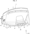
- Figure 4 is a plan view of the instrument panel 2 of the vehicle on which the driver monitoring device 30 according to the present embodiment is mounted. It is to be noted that some vehicles have no passenger seats. The "passenger seat side" will therefore refer to the opposite side to driver's seat side in a vehicle having no passenger seat.
- the driver monitoring system 50 includes the imaging unit 33, the driver monitoring device 30 for monitoring the state of a driver, and the transmitter 31.
- the imaging unit 33 includes the receiver 32 mounted on the upper portion of the instrument panel 2 of a vehicle.
- the driver monitoring device 30 is disposed on the instrument panel 2.
- the transmitter 31 is disposed on the instrument panel 2.
- the instrument panel 2 of the vehicle on which the driver monitoring system 50 is mounted will be described with reference to Figures 1 , 3 , and 4 .
- the front portion of the vehicle compartment 100 is provided with the instrument panel 2 below a front windshield 1.
- the instrument panel 2 extends in the vehicle width direction.
- a steering wheel 3 for steering the traveling direction of the vehicle is attached to the portion (the right portion in Figure 1 ) of the instrument panel 2 on the driver's seat side.
- An onboard device 20 described below is attached to the middle portion of the instrument panel 2.
- the instrument panel 2 includes an upper member 4 and a lower member 5 that are vertically disposed.
- the upper member 4 includes a top surface portion 6 and a rear surface portion 7.
- the top surface portion 6 faces upward and extends in the vehicle width direction to connect both sides of the vehicle compartment 100.
- the front windshield 1 is disposed on the front side of the top surface portion 6.
- the rear surface portion 7 is disposed between the top surface portion 6 and the lower member 5 and extends in the vehicle width direction to connect both sides of the vehicle compartment 100.
- the rear surface portion 7 includes a vertical surface portion 7a, a flat surface portion 7b, and an upward slope portion 7c.
- the upper end of the vertical surface portion 7a connects to the rear end of the top surface portion 6.
- the vertical surface portion 7a faces rearward.
- the front end of the flat surface portion 7b connects to the lower end of the vertical surface portion 7a.
- the flat surface portion 7b faces upward.
- the upper end of the upward slope portion 7c connects to the rear end of the flat surface portion 7b and the lower end of the upward slope portion 7c connects to the upper end of the lower member 5.
- the upward slope portion 7c is formed to be sloped rearward from the upper end of the upward slope portion 7c to the lower side.
- the upward slope portion 7c is formed to be sloped upward.
- the upward slope portion 7c is disposed from the end of the instrument panel 2 on the passenger seat side in the vehicle width direction to the column cover.
- the position of the upward slope portion 7c in the up-down direction is substantially the same as the central position of the steering wheel 3 or is disposed slightly lower than the central position of the steering wheel 3.
- the upward slope portion 7c of the rear surface portion 7 includes a driver's seat side slope portion 7d and a passenger seat side slope portion 7e.
- the driver's seat side slope portion 7d has a design surface (the surface toward the inside of the vehicle compartment) having the passenger seat side sloped to be positioned further rearward than the driver's seat side. That is, the design surface is sloped forward from the passenger seat side to the driver's seat side and directed toward the driver's seat side.
- the passenger seat side slope portion 7e has a design surface adjacent to the driver's seat side slope portion 7d on the passenger seat side, having the driver's seat side inclined to be positioned further rearward than the passenger seat side, and directed toward the passenger seat side.
- the upward slope portion 7c includes the driver's seat side slope portion 7d having a design surface sloped toward the driver's seat side with respect to the vehicle width direction reference line S and the passenger seat side slope portion 7e having a design surface sloped toward the passenger seat side with respect to the vehicle width direction reference line S.
- the inclination angle of the driver's seat side slope portion 7d to the vehicle width direction reference line S is ⁇ degrees.
- the connection portion between the driver's seat side slope portion 7d and the passenger seat side slope portion 7e serves as a bulging portion 7f that bulges further rearward than both sides of the rear surface portion 7 in the vehicle width direction.
- the upward slope portion 7c of the rear surface portion 7 is formed in the shape of a mountain in which the bulging portion 7f bulges rearward.
- the rear end of the flat surface portion 7b connecting the upper end of the upward slope portion 7c is formed in the shape of a mountain in accordance with the shapes of the driver's seat side slope portion 7d and the passenger seat side slope portion 7e included in the upward slope portion 7c.
- the bulging portion 7f formed by connecting the driver's seat side slope portion 7d and the passenger seat side slope portion 7e is positioned closer to the passenger seat side than the center of the instrument panel 2 in the vehicle width direction.
- the driver's seat side slope portion 7d and the passenger seat side slope portion 7e are both formed to be sloped downward from the front to the rear. That is, the driver's seat side slope portion 7d and the passenger seat side slope portion 7e are both formed to be sloped upward.
- the middle portion of the upper member 4 in the vehicle width direction is provided with the onboard device 20.
- the upper member 4 is included in the upper portion side of the instrument panel 2.
- the onboard device 20 is disposed in the middle of the instrument panel 2 in the vehicle width direction so as not to overlap on the steering wheel 3 in the vehicle width direction.
- the onboard device 20 is incorporated in the instrument panel 2 to rise from the flat surface portion 7b of the rear surface portion 7 across the top surface portion 6 and the rear surface portion 7.
- the onboard device 20 is disposed at the position corresponding to the driver's seat side slope portion 7d in the flat surface portion 7b, the rear end of which connects to the upper end of the upward slope portion 7c.
- the onboard device 20 is thus disposed closer to the driver's seat side than the bulging portion 7f in the vehicle width direction.
- the onboard device 20 is disposed along the slope of the driver's seat side slope portion 7d in plan view.
- the onboard device 20 is therefore inclined in the direction of the driver's side. It is to be noted that the upward slope portion 7c is disposed below the onboard device 20.
- the onboard device 20 according to the present embodiment is an onboard device incorporated in the instrument panel 2.
- the onboard device 20 according to the present embodiment is not a so-called retrofittable onboard device.
- the onboard device 20 is a display device including a display unit 21 and an outer frame 22.
- the display unit 21 is a display that displays information.
- the outer frame 22 holds the outer periphery of the display unit 21.
- the display unit 21 has a substantially rectangular shape.
- the outer frame 22 that holds the display unit 21 has a horizontally long shape in which the dimensions in the vehicle width direction are longer than the dimensions in the up-down direction.
- the onboard device 20 is a navigation device that assists a person driving (driver) in driving.
- the onboard device 20 is a navigation device, but this is not limiting.
- the onboard device 20 may be an audio device or a display device that displays speed, number of revolutions, or the like. It is to be noted that the end of the outer frame 22 of the onboard device 20 on the passenger seat side substantially agrees with the bulging portion 7f disposed below the onboard device 20 in the vehicle width direction.
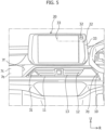
- Figure 5 is a partially enlarged view of the area close to the middle of the instrument panel 2 in the vehicle width direction.
- Figure 6 is a partially enlarged view of the upward slope portion 7c in the area close to the middle of the instrument panel 2 in the vehicle width direction.
- the driver's seat side slope portion 7d of the upward slope portion 7c is provided with a recess-shaped portion 10 that is formed to be positioned in the middle of the instrument panel 2 in the vehicle width direction and recessed from the design surface of the driver's seat side slope portion 7d.
- the recess-shaped portion 10 is positioned in the middle of the instrument panel 2 in the vehicle width direction.
- the end of the recess-shaped portion 10 on the passenger seat side in the vehicle width direction substantially agrees with the bulging portion 7f in the vehicle width direction.
- the recess-shaped portion 10 is disposed slightly lower than the central position of the steering wheel 3 in the up-down direction.
- the recess-shaped portion 10 is formed in the shape of an isosceles trapezoid having a longer bottom side than a top side.
- the driver's seat side of the recess-shaped portion 10 in the vehicle width direction overlaps on the passenger seat side of the steering wheel 3 in the vehicle width direction.
- the surface of a bottom wall 11 of the recess-shaped portion 10 on the vehicle compartment side is formed substantially in parallel with the design surface of the driver's seat side slope portion 7d.
- the bottom wall 11 is also sloped rearward from the top side of the bottom wall 11 to the lower side, that is, is sloped upward and directed toward the driver's seat side as with the driver's seat side slope portion 7d.
- a blower outlet 12 from which airflow conditioned by an air-conditioning system (not shown) provided in the vehicle is blown is formed on the bottom wall 11.
- a louver 13 that adjusts the direction of the conditioned airflow is disposed at the blower outlet 12.
- the blower outlet 12 is formed in the shape of an isosceles trapezoid having a longer top side than a bottom side.
- a corner bottom wall 14 having a triangular shape is formed on the passenger seat side of the bottom wall 11. The corner bottom wall 14 is formed between the vertical side of the recess-shaped portion 10 on the passenger seat side and the vertical side of the blower outlet 12 on the passenger seat side.
- the corner bottom wall 14 is disposed lower than the onboard device 20 in the up-down direction.
- the corner bottom wall 14 is disposed at the position that is closer in the vehicle width direction to the passenger seat side than the center of the onboard device 20 in the vehicle width direction and at substantially the same position as that of the end of the onboard device 20 on the passenger seat side.
- the corner bottom wall 14 is thus adjacent to the bulging portion 7f on the driver's seat side in the vehicle width direction.
- the driver monitoring system 50 is a system that monitors a dozing off state or the like of a driver of the vehicle.
- the driver monitoring system 50 includes the driver monitoring device 30, the transmitter 31 that transmits a sensing wave toward the driver, and the imaging unit 33 including the receiver 32 and an imaging element 37.
- the receiver 32 receives reflected light waves reflected by the driver.
- the imaging element 37 converts the reflected light waves received by the receiver 32 to an electrical signal.
- the imaging unit 33 is provided in the onboard device 20.
- the driver monitoring device 30 connects to the transmitter 31 and the imaging unit 33.
- the driver monitoring device 30 transmits a control signal for transmitting a sensing wave to the transmitter 31.
- the driver monitoring device 30 transmits a control signal related to the image capturing of the driver to the imaging unit 33 and receives imaging information from the imaging unit 33.
- the transmitter 31 transmits a sensing wave toward the driver, but the driver is not necessarily in the driver's seat. The sensing wave is thus transmitted toward the driver in a case in which the driver is in the driver's seat. In a case in which the driver is not in the driver's seat, the sensing wave is transmitted toward the driver's seat side.
- the reflected light waves received by the receiver 32 includes a sensing wave transmitted toward the driver (driver's seat side) from the transmitter 31 and is reflected by the driver (driver's seat side).
- the reflected light waves received by the receiver 32 sometimes includes, for example, external light such as sunlight hitting the driver (driver's seat side) which will be reflected by the driver (driver's seat side) in addition to the sensing wave reflected by the driver (driver's seat side).
- the receiver 32 sometimes receives external light directly in addition to the reflected light waves reflected by the driver (driver's seat side).
- the reflected light waves received by the receiver 32 are sensing waves transmitted toward the driver (driver's seat side) from the transmitter 31 and reflected by the driver (driver's seat side).
- the reflected light waves received by the receiver 32 thus includes sensing waves transmitted toward the driver (driver's seat side) from the transmitter 31 and reflected by the driver (driver's seat side).
- the sensing wave transmitted by the transmitter 31 is an electromagnetic wave including, for example, light such as infrared light.
- the transmitter 31 is, for example, a light-emitting unit that emits light such as infrared light serving as a sensing wave on the face of the driver (driver's seat side).
- the receiver 32 is, for example, a camera lens that receives light such as an infrared light serving as a sensing wave which is transmitted toward the driver (driver's seat side) from the transmitter 31 and is reflected by the driver (driver's seat side) to return.
- the imaging unit 33 is, for example, a camera that captures an image of the driver (driver's seat side) based on light such as infrared light serving as a sensing wave received by the receiver 32.
- the imaging unit 33 includes the imaging element 37 (e.g., CMOS image sensor) that converts incident light formed as an image by the camera lens which is the receiver 32 to an electrical signal.
- the emission plane of a sensing wave transmitted from the transmitter 31 faces the driver (driver's seat side) and the incident plane of the receiver 32 that receives the sensing wave faces the driver (driver's seat side).
- the imaging unit 33 includes the receiver 32 and the imaging element 37 and the imaging unit 33 is provided upright to be sandwiched by the outer frame 22 of the onboard device 20 and the instrument panel 2 in the present embodiment. More specifically, the imaging unit 33 is provided upright to be sandwiched by the vertical frame of the outer frame 22 on the driver's seat side and the instrument panel 2, and the receiver 32 is exposed to the design surface from a hole formed in the outer frame 22.
- the imaging unit 33 (imaging element 37) including the receiver 32 is thus provided to the outer frame.
- the imaging element 37 of the imaging unit 33 may not, however, be provided to the outer frame 22, but may be provided to the driver monitoring device 30 through an optical fiber or the like.
- the driver monitoring device 30 is provided on the instrument panel 2.
- the driver monitoring device 30 includes a sensing wave control unit 35, an imaging control unit 36, and a state determination unit 38.
- the sensing wave control unit 35 transmits, to the transmitter 31, a control signal related to the transmission of a sensing wave.
- the imaging control unit 36 transmits, to the imaging unit 33, a control signal related to the image capturing of a driver.
- the imaging control unit 36 receives the captured image of the state of the driver that is transmitted from the imaging unit 33 and processes the received image.
- the state determination unit 38 determines the state of the driver based on information transmitted from the imaging control unit 36 and subjected to image processing.
- the state determination unit 38 transmits a result of the determination of the state of the driver to an output device 39 disposed on the instrument panel 2.
- the output device 39 notifies the driver by transmitting, to a center-mounted instrument or the like, the result of the determination of the state of the driver transmitted from the state determination unit 38. It is to be noted that not only may the result of the determination of the state of the driver be transmitted to the center-mounted instrument or the like, but sounds may also be emitted or the seat may also be, for example, vibrated to notify the driver.
- the driver monitoring device 30 connects to a vehicle control device and transmits the state of the driver determined by the state determination unit 38 to the vehicle control device.
- the imaging unit 33 including the receiver 32 is provided to the outer frame 22 of the onboard device 20.
- the receiver 32 is disposed at the upper right portion of the outer frame 22 to be disposed closer to the driver's seat side with respect to the middle of the onboard device 20 in the vehicle width direction.
- the receiver 32 is thus disposed at a position that is closer to the passenger seat side than the driver's seat side in the vehicle width direction of the instrument panel 2 and does not overlap on the steering wheel 3.
- the corner bottom wall 14 having a triangular shape and formed between the vertical side of the recess-shaped portion 10 on the passenger seat side and the vertical side of the blower outlet 12 on the passenger seat side is formed on the passenger seat side of the bottom wall 11 of the recess-shaped portion 10.
- the transmitter 31 is disposed to be buried in the corner bottom wall 14.
- the transmitter 31 is formed to have a triangular shape smaller than that of the corner bottom wall 14.
- the transmitter 31 is disposed to allow the surface of the corner bottom wall 14 on the vehicle compartment side and the surface of the transmitter 31 on the vehicle compartment side to have the same height and be flat.
- the corner bottom wall 14 is disposed lower than the onboard device 20 in the up-down direction and disposed at substantially the same position as that of the end of the onboard device 20 on the passenger seat side in the vehicle width direction.
- the transmitter 31 is thus disposed lower than the onboard device 20 in the up-down direction and disposed at substantially the same position as that of the end of the onboard device 20 on the passenger seat side in the vehicle width direction.
- the transmitter 31 is thus disposed apart from the receiver 32 farther than the distance between the upper right corner portion and the lower left corner portion of the onboard device 20 having a horizontally long shape.
- the transmitter 31 and the receiver 32 included in the driver monitoring device 30 according to the present embodiment therefore make it possible to reduce a so-called red-eye effect at the time of image capturing.
- the transmitter 31 is disposed on the corner bottom wall 14 of the bottom wall 11 of the recess-shaped portion 10. This makes it possible to prevent light cast from the transmitter 31 from being blocked by an arm of an occupant because the transmitter 31 is disposed next to the louver 13 that is operated less frequently than another switch member (not shown) disposed on the instrument panel 2.
- the transmitter 31 is disposed on the corner bottom wall 14 of the bottom wall 11 formed to be recessed on the driver's seat side slope portion 7d. This makes it possible to prevent an object from hitting the transmitter 31 even in a case in which the object hits the driver's seat side slope portion 7d.
- the position of the upward slope portion 7c in the up-down direction is substantially the same as the central position of the steering wheel 3 or disposed slightly lower than the central position of the steering wheel 3.
- the transmitter 31 is thus disposed at substantially the same position as the central position of the steering wheel 3 or slightly lower than the central position of the steering wheel 3 in the up-down direction.
- the transmitter 31 is disposed on the corner bottom wall 14 of the bottom wall 11 sloped upward. The transmitter 31 therefore casts light on the face of the driver from a side lower than the face of the driver.
- the transmitter 31 included in the driver monitoring device 30 according to the present embodiment thus makes it possible to reliably illuminate the face of the driver even when the driver is wearing a hat, a cap, or the like. In addition, it is possible to prevent the face of an occupant sitting on the seat at the rear of the driver from being illuminated.
- the corner bottom wall 14 is adjacent to the bulging portion 7f on the driver's seat side in the vehicle width direction.
- the transmitter 31 disposed on the corner bottom wall 14 is thus disposed near the end portion of the driver's seat side slope portion 7d on the passenger seat side.
- the transmitter 31 included in the driver monitoring device 30 according to the present embodiment therefore makes it possible to reliably illuminate the face of the driver even when the driver is wearing a hat, a cap, or the like.
- the recess-shaped portion 10 is provided to the driver's seat side slope portion 7d.
- the corner bottom wall 14 is disposed on the bottom wall 11 of the recess-shaped portion 10.
- the bottom wall 11 is formed substantially in parallel with the design surface of the driver's seat side slope portion 7d. This inclines the transmitter 31 disposed on the corner bottom wall 14 in the direction of the driver side as with the onboard device 20.
- the onboard device 20 and the transmitter 31 are thus inclined in the direction of the driver side. This facilitates the driver monitoring device 30 so as to easily recognize the driver.
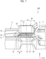
- the receiver 32 is disposed at the upper right portion of the outer frame 22 of the onboard device 20, but the receiver 32 may be disposed at the outer frame 22 and positioned in the vehicle width direction between the passenger seat end of the display unit 21 in the vehicle width direction and the passenger seat end of the steering wheel 3 in the vehicle width direction (the area of an arrow A in Figure 7 ).
- the transmitter 31 may be disposed closer to the passenger seat side than the vertical side of the blower outlet 12 on the passenger seat side in the vehicle width direction and between the passenger seat end (the opposite side to the passenger seat end in the vehicle width direction) of the onboard device 20 in the vehicle width direction and the passenger seat end (the opposite side to passenger seat end in the vehicle width direction) of the display unit 21 in the vehicle width direction (the area of an arrow B in Figure 7 ).
- the louver 13 is disposed at the blower outlet 12. It is to be noted that the blower outlet 12 is disposed lower than the onboard device 20.
- the transmitter 31 is positioned between the upper and lower ends of the blower outlet 12 (the area of arrow C in Figure 7 ) in the up-down direction.
- the transmitter 31 is disposed closer to the passenger seat side than the vertical side of the blower outlet 12 on the passenger seat side.
- the blower outlet 12 is disposed below the onboard device 20. That is, the transmitter 31 is disposed slightly lower than the central position of the steering wheel 3 in the up-down direction. This makes it possible to reliably illuminate the face of the driver even when the driver is wearing a hat, a cap, or the like. In addition, it is possible to prevent the face of an occupant sitting on the seat at the rear of the driver from being illuminated.
- the driver monitoring system 50 includes the transmitter 31, the imaging unit 33, and the driver monitoring device 30.
- the transmitter 31 transmits a sensing wave toward the driver's seat side of the vehicle.
- the imaging unit 33 includes the receiver 32 that receives reflected light waves reflected by the driver's seat side.
- the imaging unit 33 captures an image of a driver based on the reflected light waves received by the receiver 32.
- the driver monitoring device 30 monitors the state of the driver based on information from the imaging unit 33.
- the onboard device 20 is provided to the upper portion of the instrument panel 2 of the vehicle and the onboard device 20 includes the display unit 21 and the outer frame 22.
- the display unit 21 displays information.
- the outer frame 22 holds the outer periphery of the display unit 21.
- the receiver 32 is disposed on the driver's seat side of the outer frame 22.
- the transmitter 31 is disposed lower than the onboard device 20 and closer to the opposite side to the driver's seat side than the middle of the onboard device 20 in the vehicle width direction on the instrument panel 2.
- This configuration makes it possible to capture a clear image of the face of the driver while preventing the imaging unit 33 from receiving a sensing wave of the transmitter 31 that hits an occupant at the rear of the driver's seat.
- the instrument panel 2 includes the upward slope portion 7c lower than the onboard device 20.
- the upward slope portion 7c has a design surface sloped rearward from the upper side to the lower side.
- the transmitter 31 is disposed at the upward slope portion 7c.
- This configuration allows the transmitter 31 to emit from the lower side to the upper side. It is thus possible to reliably illuminate the face of the driver even when the driver is wearing a hat or a cap. It is possible to prevent the face of an occupant sitting in the seat at the rear of the driver from being illuminated.
- the instrument panel 2 includes the driver's seat side slope portion 7d having a design surface sloped forward from the passenger seat side to the driver's seat side and directed toward the driver's seat side.
- the onboard device 20 and the transmitter 31 are disposed along the driver's seat side slope portion 7d.
- This configuration inclines the onboard device 20 and the transmitter 31 toward the driver side. This further facilitates recognition of the driver.
- the transmitter 31 is disposed near the end portion of the driver's seat side slope portion 7d on the passenger seat side.
- the disposition of the transmitter 31 near the end portion of the driver's seat side slope portion 7d on the passenger seat side brings the transmitter 31 closer to the driver's side. This further facilitates the driver monitoring device 30 to recognize the driver.
- the imaging unit 33 includes the receiver 32 and the imaging element 37.
- the imaging unit 33 is provided upright to be sandwiched by the vertical frame of the outer frame 22 of the onboard device 20 on the driver's seat side and the instrument panel 2. This allows the imaging element 37 of the imaging unit 33 to be provided in the onboard device 20.
- the imaging element 37 need not, however, be provided in the onboard device 20.
- the imaging element 37 of the imaging unit 33 may be provided to the driver monitoring device 30 through an optical fiber or the like.
- the imaging unit 33 is provided upright to be sandwiched by the vertical frame of the outer frame 22 on the driver's seat side and the instrument panel 2, but the imaging unit 33 may be provided sideways on the upper portion side of the onboard device 20 as indicated by the two-dot chain line in Figure 5 . It is, however, desirable even in that case that the receiver 32 be disposed at the upper right portion of the outer frame 22.
Landscapes
- Engineering & Computer Science (AREA)
- Theoretical Computer Science (AREA)
- Transportation (AREA)
- Chemical & Material Sciences (AREA)
- Mechanical Engineering (AREA)
- General Engineering & Computer Science (AREA)
- Physics & Mathematics (AREA)
- General Physics & Mathematics (AREA)
- Combustion & Propulsion (AREA)
- Human Computer Interaction (AREA)
- Multimedia (AREA)
- Fittings On The Vehicle Exterior For Carrying Loads, And Devices For Holding Or Mounting Articles (AREA)
- Instrument Panels (AREA)
Abstract
Description
- The present invention relates to a driver monitoring system for monitoring the state of a driver.
- It has been known to provide a driver image capturing device that captures an image of the face of a driver of a vehicle in the vehicle compartment to monitor the state of the driver.
- For example, the driver image capturing device disclosed in
Figure 1 ofPatent Literature 1 is a driver image capturing device for capturing an image of a driver in a vehicle in which an onboard device rises from the upper surface of the middle portion of an instrument panel in the vehicle width direction. The driver image capturing device includes a camera lens and a light-emitting unit. The camera lens is built in the onboard device and has an incident plane facing the driver side. The light-emitting unit is built in the onboard device and has an emission plane facing the driver side. The camera lens is provided at the end portion of the onboard device on the driver's seat side in the vehicle width direction. The light-emitting unit is provided at the end portion of the onboard device on the passenger seat side in the vehicle width direction. In addition, the driver image capturing device disclosed inFigure 5 ofPatent Literature 1 is a driver image capturing device for capturing an image of a driver in a vehicle in which an onboard device rises from the upper surface of the middle portion of an instrument panel in the vehicle width direction and a hazard lamp switch is provided at the middle portion of the instrument panel in the vehicle width direction below the onboard device and in the middle between the upper and lower ends of the steering wheel in the vehicle up-down direction. The driver image capturing device includes a camera lens and a light-emitting unit. The camera lens is built in the end portion of an outer frame at both ends of the hazard lamp switch in the vehicle width direction on the driver's seat side in the vehicle width direction and the upper side in the up-down direction. The light-emitting unit is built in the end portion of the outer frame at both ends of the hazard lamp switch in the vehicle width direction on the passenger seat side in the vehicle width direction and the lower side in the up-down direction. - [Patent Literature 1]
JP 6481970 B2 - The driver image capturing device disclosed in
Figure 1 ofPatent Literature 1 is provided with the light-emitting unit in the onboard device rising from the upper surface of the middle portion of the instrument panel in the vehicle width direction. The seat side at the rear of the driver is thus also illuminated with light of the light-emitting unit. The light hitting the face of an occupant sitting on the seat at the rear of the driver is also received by the image capturing device as noise. The face of the occupant sitting in the back seat may therefore be recognized in error as the face of the driver. - In addition, when the camera lens is disposed at the hazard lamp switch provided below the onboard device rising on the upper surface of the middle portion of the instrument panel in the vehicle width direction as in
Figure 5 ofPatent Literature 1, the camera lens and the face of an occupant have a longer distance therebetween. This may prevent the face of the driver from being clearly recognized. - Accordingly, an object of the present invention is to provide a driver monitoring system including an imaging unit capable of capturing a clear image of the face of a driver while preventing a receiver from receiving light of a light-emitting unit that hits an occupant at the rear of a driver's seat.
- An aspect of the present invention is a driver monitoring system including: a transmitter; an imaging unit; and a driver monitoring device. The transmitter is configured to transmit a sensing wave toward a driver's seat side of a vehicle. The imaging unit includes a receiver that receives reflected light waves reflected by the driver's seat side. The imaging unit is configured to capture an image of a driver based on the reflected light waves received by the receiver. The driver monitoring device is configured to monitor a state of the driver based on information from the imaging unit. An onboard device is provided to an upper portion of an instrument panel of the vehicle and the onboard device includes a display unit and an outer frame. The display unit displays information. The outer frame holds an outer periphery of the display unit. The receiver is disposed on the driver's seat side of the outer frame. The transmitter is disposed lower than the onboard device and closer to an opposite side to the driver's seat side than the middle of the onboard device in the vehicle width direction on the instrument panel.
- According to the present invention, a driver monitoring system is provided including an imaging unit capable of capturing a clear image of the face of a driver while preventing a receiver from receiving light of a light-emitting unit that hits an occupant at the rear of a driver's seat.
-
- [
Figure 1] Figure 1 is a front view of an instrument panel of a vehicle on which a driver monitoring system according to the present embodiment is mounted. - [
Figure 2] Figure 2 is a control block diagram of the driver monitoring system according to the present embodiment. - [
Figure 3] Figure 3 is a longitudinal sectional view of the instrument panel of a vehicle on which a driver monitoring device according to the present embodiment is mounted. - [
Figure 4] Figure 4 is a plan view of the instrument panel of the vehicle on which the driver monitoring system according to the present embodiment is mounted. - [
Figure 5] Figure 5 is a partially enlarged view of the instrument panel including the driver monitoring system according to the present embodiment. - [
Figure 6] Figure 6 is a partially enlarged view of the instrument panel including a transmitter of the driver monitoring system according to the present embodiment. - [
Figure 7] Figure 7 is a front view of the instrument panel for describing disposition of the driver monitoring system according to the present embodiment. - An embodiment of a
driver monitoring system 50 according to the present invention is described below with reference to the appended drawings. Thedriver monitoring system 50 includes adriver monitoring device 30, atransmitter 31, and animaging unit 33 including areceiver 32. It is to be noted that an arrow Fr indicates the front in the vehicle front-rear direction in the drawings. An arrow R indicates the right side of an occupant looking toward the front of the vehicle. An arrow U indicates the upper side of the vehicle. In addition, a central line connecting the respective centers of the left and right wheels on the front side or the rear side in a case in which a vehicle travels straight will be referred to as a vehicle width direction reference line S below. -
Figure 1 is a front view of aninstrument panel 2 of a vehicle in which a portion of theinstrument panel 2 on the passenger seat side (the left portion inFigure 1 ) is removed. Thedriver monitoring system 50 according to the present embodiment is mounted on the vehicle. It is to be noted that an embodiment of a so-called right-hand drive in which a driver's seat is disposed on the right side of avehicle compartment 100 when facing the front of the vehicle is described as the present embodiment. However, in the case of a so-called left-hand drive in which a driver's seat is disposed on the left side of thevehicle compartment 100 when facing the front of the vehicle, the formation is symmetrical to the formation illustrated inFigure 1 .Figure 2 is an example of a control block diagram of thedriver monitoring system 50 according to the present invention.Figure 3 is a longitudinal sectional view of theinstrument panel 2 of the vehicle on which thedriver monitoring device 30 according to the present embodiment is mounted.Figure 4 is a plan view of theinstrument panel 2 of the vehicle on which thedriver monitoring device 30 according to the present embodiment is mounted. It is to be noted that some vehicles have no passenger seats. The "passenger seat side" will therefore refer to the opposite side to driver's seat side in a vehicle having no passenger seat. - The
driver monitoring system 50 according to the present invention includes theimaging unit 33, thedriver monitoring device 30 for monitoring the state of a driver, and thetransmitter 31. Theimaging unit 33 includes thereceiver 32 mounted on the upper portion of theinstrument panel 2 of a vehicle. Thedriver monitoring device 30 is disposed on theinstrument panel 2. Thetransmitter 31 is disposed on theinstrument panel 2. Theinstrument panel 2 of the vehicle on which thedriver monitoring system 50 is mounted will be described with reference toFigures 1 ,3 , and4 . As illustrated inFigure 1 , the front portion of thevehicle compartment 100 is provided with theinstrument panel 2 below afront windshield 1. Theinstrument panel 2 extends in the vehicle width direction. Asteering wheel 3 for steering the traveling direction of the vehicle is attached to the portion (the right portion inFigure 1 ) of theinstrument panel 2 on the driver's seat side. Anonboard device 20 described below is attached to the middle portion of theinstrument panel 2. - The
instrument panel 2 includes anupper member 4 and alower member 5 that are vertically disposed. Theupper member 4 includes atop surface portion 6 and arear surface portion 7. Thetop surface portion 6 faces upward and extends in the vehicle width direction to connect both sides of thevehicle compartment 100. Thefront windshield 1 is disposed on the front side of thetop surface portion 6. Therear surface portion 7 is disposed between thetop surface portion 6 and thelower member 5 and extends in the vehicle width direction to connect both sides of thevehicle compartment 100. - The
rear surface portion 7 includes avertical surface portion 7a, aflat surface portion 7b, and anupward slope portion 7c. The upper end of thevertical surface portion 7a connects to the rear end of thetop surface portion 6. Thevertical surface portion 7a faces rearward. The front end of theflat surface portion 7b connects to the lower end of thevertical surface portion 7a. Theflat surface portion 7b faces upward. The upper end of theupward slope portion 7c connects to the rear end of theflat surface portion 7b and the lower end of theupward slope portion 7c connects to the upper end of thelower member 5. As illustrated inFigure 3 , theupward slope portion 7c is formed to be sloped rearward from the upper end of theupward slope portion 7c to the lower side. That is, theupward slope portion 7c is formed to be sloped upward. Theupward slope portion 7c is disposed from the end of theinstrument panel 2 on the passenger seat side in the vehicle width direction to the column cover. The position of theupward slope portion 7c in the up-down direction is substantially the same as the central position of thesteering wheel 3 or is disposed slightly lower than the central position of thesteering wheel 3. - In addition, as illustrated in
Figure 4 , theupward slope portion 7c of therear surface portion 7 includes a driver's seatside slope portion 7d and a passenger seatside slope portion 7e. The driver's seatside slope portion 7d has a design surface (the surface toward the inside of the vehicle compartment) having the passenger seat side sloped to be positioned further rearward than the driver's seat side. That is, the design surface is sloped forward from the passenger seat side to the driver's seat side and directed toward the driver's seat side. The passenger seatside slope portion 7e has a design surface adjacent to the driver's seatside slope portion 7d on the passenger seat side, having the driver's seat side inclined to be positioned further rearward than the passenger seat side, and directed toward the passenger seat side. That is, theupward slope portion 7c includes the driver's seatside slope portion 7d having a design surface sloped toward the driver's seat side with respect to the vehicle width direction reference line S and the passenger seatside slope portion 7e having a design surface sloped toward the passenger seat side with respect to the vehicle width direction reference line S. The inclination angle of the driver's seatside slope portion 7d to the vehicle width direction reference line S is α degrees. The connection portion between the driver's seatside slope portion 7d and the passenger seatside slope portion 7e serves as a bulgingportion 7f that bulges further rearward than both sides of therear surface portion 7 in the vehicle width direction. That is, in a case in which theinstrument panel 2 is viewed from above (plan view) as illustrated inFigure 4 , theupward slope portion 7c of therear surface portion 7 is formed in the shape of a mountain in which the bulgingportion 7f bulges rearward. - The rear end of the
flat surface portion 7b connecting the upper end of theupward slope portion 7c is formed in the shape of a mountain in accordance with the shapes of the driver's seatside slope portion 7d and the passenger seatside slope portion 7e included in theupward slope portion 7c. The bulgingportion 7f formed by connecting the driver's seatside slope portion 7d and the passenger seatside slope portion 7e is positioned closer to the passenger seat side than the center of theinstrument panel 2 in the vehicle width direction. The driver's seatside slope portion 7d and the passenger seatside slope portion 7e are both formed to be sloped downward from the front to the rear. That is, the driver's seatside slope portion 7d and the passenger seatside slope portion 7e are both formed to be sloped upward. - As illustrated in
Figure 1 , the middle portion of theupper member 4 in the vehicle width direction is provided with theonboard device 20. Theupper member 4 is included in the upper portion side of theinstrument panel 2. Specifically, theonboard device 20 is disposed in the middle of theinstrument panel 2 in the vehicle width direction so as not to overlap on thesteering wheel 3 in the vehicle width direction. Theonboard device 20 is incorporated in theinstrument panel 2 to rise from theflat surface portion 7b of therear surface portion 7 across thetop surface portion 6 and therear surface portion 7. In addition, theonboard device 20 is disposed at the position corresponding to the driver's seatside slope portion 7d in theflat surface portion 7b, the rear end of which connects to the upper end of theupward slope portion 7c. Theonboard device 20 is thus disposed closer to the driver's seat side than the bulgingportion 7f in the vehicle width direction. - In addition, the
onboard device 20 is disposed along the slope of the driver's seatside slope portion 7d in plan view. Theonboard device 20 is therefore inclined in the direction of the driver's side. It is to be noted that theupward slope portion 7c is disposed below theonboard device 20. Theonboard device 20 according to the present embodiment is an onboard device incorporated in theinstrument panel 2. Theonboard device 20 according to the present embodiment is not a so-called retrofittable onboard device. - The
onboard device 20 is a display device including adisplay unit 21 and anouter frame 22. Thedisplay unit 21 is a display that displays information. Theouter frame 22 holds the outer periphery of thedisplay unit 21. Thedisplay unit 21 has a substantially rectangular shape. Theouter frame 22 that holds thedisplay unit 21 has a horizontally long shape in which the dimensions in the vehicle width direction are longer than the dimensions in the up-down direction. In the present embodiment, theonboard device 20 is a navigation device that assists a person driving (driver) in driving. In the present embodiment, theonboard device 20 is a navigation device, but this is not limiting. Theonboard device 20 may be an audio device or a display device that displays speed, number of revolutions, or the like. It is to be noted that the end of theouter frame 22 of theonboard device 20 on the passenger seat side substantially agrees with the bulgingportion 7f disposed below theonboard device 20 in the vehicle width direction. - Next, the specific shape of the
upward slope portion 7c in the middle of theinstrument panel 2 in the vehicle width direction will be described with reference toFigures 1 ,5 , and6 .Figure 5 is a partially enlarged view of the area close to the middle of theinstrument panel 2 in the vehicle width direction.Figure 6 is a partially enlarged view of theupward slope portion 7c in the area close to the middle of theinstrument panel 2 in the vehicle width direction. As illustrated inFigures 1 ,5 , and6 , the driver's seatside slope portion 7d of theupward slope portion 7c is provided with a recess-shapedportion 10 that is formed to be positioned in the middle of theinstrument panel 2 in the vehicle width direction and recessed from the design surface of the driver's seatside slope portion 7d. The recess-shapedportion 10 is positioned in the middle of theinstrument panel 2 in the vehicle width direction. The end of the recess-shapedportion 10 on the passenger seat side in the vehicle width direction substantially agrees with the bulgingportion 7f in the vehicle width direction. In addition, the recess-shapedportion 10 is disposed slightly lower than the central position of thesteering wheel 3 in the up-down direction. The recess-shapedportion 10 is formed in the shape of an isosceles trapezoid having a longer bottom side than a top side. The driver's seat side of the recess-shapedportion 10 in the vehicle width direction overlaps on the passenger seat side of thesteering wheel 3 in the vehicle width direction. The surface of abottom wall 11 of the recess-shapedportion 10 on the vehicle compartment side is formed substantially in parallel with the design surface of the driver's seatside slope portion 7d. Thebottom wall 11 is also sloped rearward from the top side of thebottom wall 11 to the lower side, that is, is sloped upward and directed toward the driver's seat side as with the driver's seatside slope portion 7d. - A
blower outlet 12 from which airflow conditioned by an air-conditioning system (not shown) provided in the vehicle is blown is formed on thebottom wall 11. Alouver 13 that adjusts the direction of the conditioned airflow is disposed at theblower outlet 12. Theblower outlet 12 is formed in the shape of an isosceles trapezoid having a longer top side than a bottom side. Acorner bottom wall 14 having a triangular shape is formed on the passenger seat side of thebottom wall 11. Thecorner bottom wall 14 is formed between the vertical side of the recess-shapedportion 10 on the passenger seat side and the vertical side of theblower outlet 12 on the passenger seat side. Thecorner bottom wall 14 is disposed lower than theonboard device 20 in the up-down direction. Thecorner bottom wall 14 is disposed at the position that is closer in the vehicle width direction to the passenger seat side than the center of theonboard device 20 in the vehicle width direction and at substantially the same position as that of the end of theonboard device 20 on the passenger seat side. Thecorner bottom wall 14 is thus adjacent to the bulgingportion 7f on the driver's seat side in the vehicle width direction. - Next, the
driver monitoring system 50 according to the present embodiment will be described with reference toFigure 2. Figure 2 is an example of a control block diagram of thedriver monitoring system 50 according to the present embodiment. Thedriver monitoring system 50 is a system that monitors a dozing off state or the like of a driver of the vehicle. Thedriver monitoring system 50 includes thedriver monitoring device 30, thetransmitter 31 that transmits a sensing wave toward the driver, and theimaging unit 33 including thereceiver 32 and animaging element 37. Thereceiver 32 receives reflected light waves reflected by the driver. Theimaging element 37 converts the reflected light waves received by thereceiver 32 to an electrical signal. Theimaging unit 33 is provided in theonboard device 20. Thedriver monitoring device 30 connects to thetransmitter 31 and theimaging unit 33. Thedriver monitoring device 30 transmits a control signal for transmitting a sensing wave to thetransmitter 31. In addition, thedriver monitoring device 30 transmits a control signal related to the image capturing of the driver to theimaging unit 33 and receives imaging information from theimaging unit 33. Thetransmitter 31 transmits a sensing wave toward the driver, but the driver is not necessarily in the driver's seat. The sensing wave is thus transmitted toward the driver in a case in which the driver is in the driver's seat. In a case in which the driver is not in the driver's seat, the sensing wave is transmitted toward the driver's seat side. The reflected light waves received by thereceiver 32 includes a sensing wave transmitted toward the driver (driver's seat side) from thetransmitter 31 and is reflected by the driver (driver's seat side). In addition, the reflected light waves received by thereceiver 32 sometimes includes, for example, external light such as sunlight hitting the driver (driver's seat side) which will be reflected by the driver (driver's seat side) in addition to the sensing wave reflected by the driver (driver's seat side). In addition, thereceiver 32 sometimes receives external light directly in addition to the reflected light waves reflected by the driver (driver's seat side). At night or the like, the reflected light waves received by thereceiver 32 are sensing waves transmitted toward the driver (driver's seat side) from thetransmitter 31 and reflected by the driver (driver's seat side). The reflected light waves received by thereceiver 32 thus includes sensing waves transmitted toward the driver (driver's seat side) from thetransmitter 31 and reflected by the driver (driver's seat side). - The sensing wave transmitted by the
transmitter 31 is an electromagnetic wave including, for example, light such as infrared light. Thetransmitter 31 is, for example, a light-emitting unit that emits light such as infrared light serving as a sensing wave on the face of the driver (driver's seat side). Thereceiver 32 is, for example, a camera lens that receives light such as an infrared light serving as a sensing wave which is transmitted toward the driver (driver's seat side) from thetransmitter 31 and is reflected by the driver (driver's seat side) to return. Theimaging unit 33 is, for example, a camera that captures an image of the driver (driver's seat side) based on light such as infrared light serving as a sensing wave received by thereceiver 32. Theimaging unit 33 includes the imaging element 37 (e.g., CMOS image sensor) that converts incident light formed as an image by the camera lens which is thereceiver 32 to an electrical signal. The emission plane of a sensing wave transmitted from thetransmitter 31 faces the driver (driver's seat side) and the incident plane of thereceiver 32 that receives the sensing wave faces the driver (driver's seat side). It is to be noted that theimaging unit 33 includes thereceiver 32 and theimaging element 37 and theimaging unit 33 is provided upright to be sandwiched by theouter frame 22 of theonboard device 20 and theinstrument panel 2 in the present embodiment. More specifically, theimaging unit 33 is provided upright to be sandwiched by the vertical frame of theouter frame 22 on the driver's seat side and theinstrument panel 2, and thereceiver 32 is exposed to the design surface from a hole formed in theouter frame 22. The imaging unit 33 (imaging element 37) including thereceiver 32 is thus provided to the outer frame. Theimaging element 37 of theimaging unit 33 may not, however, be provided to theouter frame 22, but may be provided to thedriver monitoring device 30 through an optical fiber or the like. Thedriver monitoring device 30 is provided on theinstrument panel 2. - The
driver monitoring device 30 includes a sensingwave control unit 35, animaging control unit 36, and astate determination unit 38. The sensingwave control unit 35 transmits, to thetransmitter 31, a control signal related to the transmission of a sensing wave. Theimaging control unit 36 transmits, to theimaging unit 33, a control signal related to the image capturing of a driver. In addition, theimaging control unit 36 receives the captured image of the state of the driver that is transmitted from theimaging unit 33 and processes the received image. Thestate determination unit 38 determines the state of the driver based on information transmitted from theimaging control unit 36 and subjected to image processing. In addition, thestate determination unit 38 transmits a result of the determination of the state of the driver to anoutput device 39 disposed on theinstrument panel 2. Theoutput device 39 notifies the driver by transmitting, to a center-mounted instrument or the like, the result of the determination of the state of the driver transmitted from thestate determination unit 38. It is to be noted that not only may the result of the determination of the state of the driver be transmitted to the center-mounted instrument or the like, but sounds may also be emitted or the seat may also be, for example, vibrated to notify the driver. Thedriver monitoring device 30 connects to a vehicle control device and transmits the state of the driver determined by thestate determination unit 38 to the vehicle control device. - The
imaging unit 33 including thereceiver 32 is provided to theouter frame 22 of theonboard device 20. Thereceiver 32 is disposed at the upper right portion of theouter frame 22 to be disposed closer to the driver's seat side with respect to the middle of theonboard device 20 in the vehicle width direction. Thereceiver 32 is thus disposed at a position that is closer to the passenger seat side than the driver's seat side in the vehicle width direction of theinstrument panel 2 and does not overlap on thesteering wheel 3. - As described above, the
corner bottom wall 14 having a triangular shape and formed between the vertical side of the recess-shapedportion 10 on the passenger seat side and the vertical side of theblower outlet 12 on the passenger seat side is formed on the passenger seat side of thebottom wall 11 of the recess-shapedportion 10. Thetransmitter 31 is disposed to be buried in thecorner bottom wall 14. Thetransmitter 31 is formed to have a triangular shape smaller than that of thecorner bottom wall 14. Thetransmitter 31 is disposed to allow the surface of thecorner bottom wall 14 on the vehicle compartment side and the surface of thetransmitter 31 on the vehicle compartment side to have the same height and be flat. Thecorner bottom wall 14 is disposed lower than theonboard device 20 in the up-down direction and disposed at substantially the same position as that of the end of theonboard device 20 on the passenger seat side in the vehicle width direction. Thetransmitter 31 is thus disposed lower than theonboard device 20 in the up-down direction and disposed at substantially the same position as that of the end of theonboard device 20 on the passenger seat side in the vehicle width direction. Thetransmitter 31 is thus disposed apart from thereceiver 32 farther than the distance between the upper right corner portion and the lower left corner portion of theonboard device 20 having a horizontally long shape. Thetransmitter 31 and thereceiver 32 included in thedriver monitoring device 30 according to the present embodiment therefore make it possible to reduce a so-called red-eye effect at the time of image capturing. - In addition, the
transmitter 31 is disposed on thecorner bottom wall 14 of thebottom wall 11 of the recess-shapedportion 10. This makes it possible to prevent light cast from thetransmitter 31 from being blocked by an arm of an occupant because thetransmitter 31 is disposed next to thelouver 13 that is operated less frequently than another switch member (not shown) disposed on theinstrument panel 2. In addition, thetransmitter 31 is disposed on thecorner bottom wall 14 of thebottom wall 11 formed to be recessed on the driver's seatside slope portion 7d. This makes it possible to prevent an object from hitting thetransmitter 31 even in a case in which the object hits the driver's seatside slope portion 7d. - In addition, the position of the
upward slope portion 7c in the up-down direction is substantially the same as the central position of thesteering wheel 3 or disposed slightly lower than the central position of thesteering wheel 3. Thetransmitter 31 is thus disposed at substantially the same position as the central position of thesteering wheel 3 or slightly lower than the central position of thesteering wheel 3 in the up-down direction. In addition, thetransmitter 31 is disposed on thecorner bottom wall 14 of thebottom wall 11 sloped upward. Thetransmitter 31 therefore casts light on the face of the driver from a side lower than the face of the driver. Thetransmitter 31 included in thedriver monitoring device 30 according to the present embodiment thus makes it possible to reliably illuminate the face of the driver even when the driver is wearing a hat, a cap, or the like. In addition, it is possible to prevent the face of an occupant sitting on the seat at the rear of the driver from being illuminated. - In addition, the
corner bottom wall 14 is adjacent to the bulgingportion 7f on the driver's seat side in the vehicle width direction. Thetransmitter 31 disposed on thecorner bottom wall 14 is thus disposed near the end portion of the driver's seatside slope portion 7d on the passenger seat side. Thetransmitter 31 included in thedriver monitoring device 30 according to the present embodiment therefore makes it possible to reliably illuminate the face of the driver even when the driver is wearing a hat, a cap, or the like. - The recess-shaped
portion 10 is provided to the driver's seatside slope portion 7d. Thecorner bottom wall 14 is disposed on thebottom wall 11 of the recess-shapedportion 10. Thebottom wall 11 is formed substantially in parallel with the design surface of the driver's seatside slope portion 7d. This inclines thetransmitter 31 disposed on thecorner bottom wall 14 in the direction of the driver side as with theonboard device 20. Theonboard device 20 and thetransmitter 31 are thus inclined in the direction of the driver side. This facilitates thedriver monitoring device 30 so as to easily recognize the driver. - Next, a variation of the disposition of the
transmitter 31 and thereceiver 32 will be described with reference toFigure 7 . It is to be noted that the positional relationship between thesteering wheel 3, theblower outlet 12 at which thelouver 13 is disposed, and theonboard device 20 inFigure 7 is the same as that of the embodiment described above. In the embodiment described above, thereceiver 32 is disposed at the upper right portion of theouter frame 22 of theonboard device 20, but thereceiver 32 may be disposed at theouter frame 22 and positioned in the vehicle width direction between the passenger seat end of thedisplay unit 21 in the vehicle width direction and the passenger seat end of thesteering wheel 3 in the vehicle width direction (the area of an arrow A inFigure 7 ). - This allows the
receiver 32 to receive a sensing wave reflected by the driver to come back without being interfered with by thesteering wheel 3 even when the end of theonboard device 20 on the driver's seat side in the vehicle width direction is disposed to overlap on thesteering wheel 3. - The
transmitter 31 may be disposed closer to the passenger seat side than the vertical side of theblower outlet 12 on the passenger seat side in the vehicle width direction and between the passenger seat end (the opposite side to the passenger seat end in the vehicle width direction) of theonboard device 20 in the vehicle width direction and the passenger seat end (the opposite side to passenger seat end in the vehicle width direction) of thedisplay unit 21 in the vehicle width direction (the area of an arrow B inFigure 7 ). Thelouver 13 is disposed at theblower outlet 12. It is to be noted that theblower outlet 12 is disposed lower than theonboard device 20. In addition, thetransmitter 31 is positioned between the upper and lower ends of the blower outlet 12 (the area of arrow C inFigure 7 ) in the up-down direction. - This makes it possible to dispose the
transmitter 31 and thereceiver 32 apart from each other. It is thus possible to reduce a so-called red-eye effect at the time of image capturing. In addition, thetransmitter 31 is disposed closer to the passenger seat side than the vertical side of theblower outlet 12 on the passenger seat side. Theblower outlet 12 is disposed below theonboard device 20. That is, thetransmitter 31 is disposed slightly lower than the central position of thesteering wheel 3 in the up-down direction. This makes it possible to reliably illuminate the face of the driver even when the driver is wearing a hat, a cap, or the like. In addition, it is possible to prevent the face of an occupant sitting on the seat at the rear of the driver from being illuminated. - In the present embodiment, the
driver monitoring system 50 includes thetransmitter 31, theimaging unit 33, and thedriver monitoring device 30. Thetransmitter 31 transmits a sensing wave toward the driver's seat side of the vehicle. Theimaging unit 33 includes thereceiver 32 that receives reflected light waves reflected by the driver's seat side. Theimaging unit 33 captures an image of a driver based on the reflected light waves received by thereceiver 32. Thedriver monitoring device 30 monitors the state of the driver based on information from theimaging unit 33. Theonboard device 20 is provided to the upper portion of theinstrument panel 2 of the vehicle and theonboard device 20 includes thedisplay unit 21 and theouter frame 22. Thedisplay unit 21 displays information. Theouter frame 22 holds the outer periphery of thedisplay unit 21. Thereceiver 32 is disposed on the driver's seat side of theouter frame 22. Thetransmitter 31 is disposed lower than theonboard device 20 and closer to the opposite side to the driver's seat side than the middle of theonboard device 20 in the vehicle width direction on theinstrument panel 2. - This configuration makes it possible to capture a clear image of the face of the driver while preventing the
imaging unit 33 from receiving a sensing wave of thetransmitter 31 that hits an occupant at the rear of the driver's seat. - In the present embodiment, the
instrument panel 2 includes theupward slope portion 7c lower than theonboard device 20. Theupward slope portion 7c has a design surface sloped rearward from the upper side to the lower side. Thetransmitter 31 is disposed at theupward slope portion 7c. - This configuration allows the
transmitter 31 to emit from the lower side to the upper side. It is thus possible to reliably illuminate the face of the driver even when the driver is wearing a hat or a cap. It is possible to prevent the face of an occupant sitting in the seat at the rear of the driver from being illuminated. - In the present embodiment, the
instrument panel 2 includes the driver's seatside slope portion 7d having a design surface sloped forward from the passenger seat side to the driver's seat side and directed toward the driver's seat side. Theonboard device 20 and thetransmitter 31 are disposed along the driver's seatside slope portion 7d. - This configuration inclines the
onboard device 20 and thetransmitter 31 toward the driver side. This further facilitates recognition of the driver. - In the present embodiment, the
transmitter 31 is disposed near the end portion of the driver's seatside slope portion 7d on the passenger seat side. The disposition of thetransmitter 31 near the end portion of the driver's seatside slope portion 7d on the passenger seat side brings thetransmitter 31 closer to the driver's side. This further facilitates thedriver monitoring device 30 to recognize the driver. - In the embodiment described above, the
imaging unit 33 includes thereceiver 32 and theimaging element 37. Theimaging unit 33 is provided upright to be sandwiched by the vertical frame of theouter frame 22 of theonboard device 20 on the driver's seat side and theinstrument panel 2. This allows theimaging element 37 of theimaging unit 33 to be provided in theonboard device 20. Theimaging element 37 need not, however, be provided in theonboard device 20. For example, theimaging element 37 of theimaging unit 33 may be provided to thedriver monitoring device 30 through an optical fiber or the like. In addition, theimaging unit 33 is provided upright to be sandwiched by the vertical frame of theouter frame 22 on the driver's seat side and theinstrument panel 2, but theimaging unit 33 may be provided sideways on the upper portion side of theonboard device 20 as indicated by the two-dot chain line inFigure 5 . It is, however, desirable even in that case that thereceiver 32 be disposed at the upper right portion of theouter frame 22. - The embodiment of the present invention and the modification example thereof have been described above, but the present invention is not limited to the embodiment and the modification example described above. It is possible to make a further modifications and alternations based on the technical concept of the present invention.
-
- 1
- Front windshield
- 2
- Instrument panel
- 3
- Steering wheel
- 4
- Upper member
- 5
- Lower member
- 6
- Top surface portion
- 7
- Rear surface portion
- 7a
- Vertical surface portion
- 7b
- Flat surface portion
- 7c
- Upward slope portion
- 7d
- Driver's seat side slope portion
- 7e
- Passenger seat side slope portion
- 7f
- Bulging portion
- 10
- Recess-shaped portion
- 11
- Bottom wall
- 12
- Blower outlet
- 13
- Louver
- 14
- Corner bottom wall
- 20
- Onboard device
- 21
- Display unit
- 22
- Outer frame
- 30
- Driver monitoring device
- 31
- Transmitter
- 32
- Receiver
- 33
- Imaging unit
- 35
- Sensing wave control unit
- 36
- Imaging control unit
- 37
- Imaging element
- 38
- State determination unit
- 39
- Output device
- 50
- Driver monitoring system
- 100
- Vehicle compartment
- S
- Vehicle width direction reference line
Claims (11)
- A driver monitoring system comprising:a transmitter configured to transmit a sensing wave toward a driver's seat side of a vehicle;an imaging unit including a receiver that receives reflected light waves reflected by the driver's seat side, the imaging unit being configured to capture an image of a driver based on the reflected light waves received by the receiver; anda driver monitoring device configured to monitor a state of the driver based on information from the imaging unit, the driver monitoring system being characterized in thatan onboard device is provided to an upper portion of an instrument panel of the vehicle and the onboard device includes a display unit and an outer frame, the display unit displaying information, the outer frame holding an outer periphery of the display unit,the receiver is disposed on a driver's seat side of the outer frame, andthe transmitter is disposed lower than the onboard device and closer to an opposite side to driver's seat side than a middle of the onboard device in a vehicle width direction on the instrument panel.
- The driver monitoring system according to claim 1, wherein the onboard device is disposed at a middle portion of the instrument panel in the vehicle width direction.
- The driver monitoring system according to claim 1, whereinthe instrument panel includes an upward slope portion lower than the onboard device, the upward slope portion having a design surface sloped rearward from an upper side to a lower side, andthe transmitter is disposed at the upward slope portion.
- The driver monitoring system according to claim 3, wherein the instrument panel includes a driver's seat side slope portion having a design surface sloped forward from the opposite side to the driver's seat side to the driver's seat side and directed toward the driver's seat side, and the onboard device and the transmitter are disposed along the driver's seat side slope portion.
- The driver monitoring system according to claim 4, wherein the transmitter is disposed near an end portion of the driver's seat side slope portion on the opposite side to driver's seat side.
- The driver monitoring system according to claim 5, whereinan emission plane of the sensing wave in the transmitter faces the driver's seat side,the receiver is disposed at an angle along the driver's seat side slope portion, and an incident plane of the reflected light waves faces the driver's seat side, andthe transmitter is disposed rearward the receiver in a plan view.
- The driver monitoring system according to claim 5, whereinthe driver's seat side slope portion is provided with a recess-shaped portion that is formed lower than the onboard device to be recessed from the design surface of the driver's seat side slope portion,a blower outlet from which conditioned airflow is blown is formed on a bottom wall of the recess-shaped portion and a louver that adjusts a direction of the conditioned airflow is disposed at the blower outlet, andthe transmitter is disposed in a corner bottom wall formed on the opposite side to driver's seat side on the bottom wall of the recess-shaped portion.
- The driver monitoring system according to any one of claims 1 to 7, whereinthe imaging unit further includes an imaging element that converts the reflected light waves received by the receiver to an electrical signal, andthe imaging element is provided in the onboard device.
- A driver monitoring system comprising:a transmitter configured to transmit a sensing wave toward a driver's seat side of a vehicle;an imaging unit including a receiver that receives reflected light waves reflected by the driver's seat side, the imaging unit being configured to capture an image of a driver based on the reflected light waves received by the receiver; anda driver monitoring device configured to monitor a state of the driver based on information from the imaging unit, the driver monitoring system being characterized in thatan onboard device is provided to an upper portion of an instrument panel of the vehicle and the onboard device includes a display unit and an outer frame, the display unit displaying information, the outer frame holding an outer periphery of the display unit,a blower outlet from which conditioned airflow is blown is formed lower than the onboard device on the instrument panel,the receiver is disposed at the outer frame,the receiver is positioned in a vehicle width direction between an opposite side to the driver's seat end of the display unit in the vehicle width direction and an opposite side to the driver's seat end of a steering wheel in the vehicle width direction,the transmitter is disposed on the instrument panel,the transmitter is positioned in the vehicle width direction closer to an opposite side to the driving seat side than a vertical side of the blower outlet on the opposite side to driving seat side in the vehicle width direction and between an opposite side to the driver's seat end of the onboard device in the vehicle width direction and the opposite side to the driver's seat end of the display unit in the vehicle width direction, andthe transmitter is disposed lower than the onboard device in an up-down direction and positioned between upper and lower ends of the blower outlet.
- The driver monitoring system according to claim 9, wherein the onboard device is disposed at a middle portion of the instrument panel in the vehicle width direction.
- The driver monitoring system according to claim 9 or 10, whereinthe imaging unit further includes an imaging element that converts the reflected light waves received by the receiver to an electrical signal, andthe imaging element is provided in the onboard device.
Applications Claiming Priority (1)
| Application Number | Priority Date | Filing Date | Title |
|---|---|---|---|
| JP2023149268A JP2025042327A (en) | 2023-09-14 | 2023-09-14 | Driver Monitoring System |
Publications (2)
| Publication Number | Publication Date |
|---|---|
| EP4523941A1 true EP4523941A1 (en) | 2025-03-19 |
| EP4523941B1 EP4523941B1 (en) | 2025-12-31 |
Family
ID=92538881
Family Applications (1)
| Application Number | Title | Priority Date | Filing Date |
|---|---|---|---|
| EP24195826.3A Active EP4523941B1 (en) | 2023-09-14 | 2024-08-22 | DRIVER MONITORING SYSTEM |
Country Status (2)
| Country | Link |
|---|---|
| EP (1) | EP4523941B1 (en) |
| JP (1) | JP2025042327A (en) |
Citations (3)
| Publication number | Priority date | Publication date | Assignee | Title |
|---|---|---|---|---|
| JP6481970B2 (en) | 2017-07-06 | 2019-03-13 | マツダ株式会社 | Driver shooting device |
| US20220266764A1 (en) * | 2021-02-24 | 2022-08-25 | Subaru Corporation | Occupant monitoring device for vehicle |
| EP4063150B1 (en) * | 2021-03-22 | 2023-07-05 | Suzuki Motor Corporation | Vehicle comprising a vehicle interior monitoring device |
-
2023
- 2023-09-14 JP JP2023149268A patent/JP2025042327A/en active Pending
-
2024
- 2024-08-22 EP EP24195826.3A patent/EP4523941B1/en active Active
Patent Citations (3)
| Publication number | Priority date | Publication date | Assignee | Title |
|---|---|---|---|---|
| JP6481970B2 (en) | 2017-07-06 | 2019-03-13 | マツダ株式会社 | Driver shooting device |
| US20220266764A1 (en) * | 2021-02-24 | 2022-08-25 | Subaru Corporation | Occupant monitoring device for vehicle |
| EP4063150B1 (en) * | 2021-03-22 | 2023-07-05 | Suzuki Motor Corporation | Vehicle comprising a vehicle interior monitoring device |
Also Published As
| Publication number | Publication date |
|---|---|
| EP4523941B1 (en) | 2025-12-31 |
| JP2025042327A (en) | 2025-03-27 |
Similar Documents
| Publication | Publication Date | Title |
|---|---|---|
| KR101702888B1 (en) | Vehicle view angle controlling apparatus, vehicle having the same and vehicle view angle controlling method | |
| CN106331446B (en) | Camera equipment and in-vehicle systems | |
| JP3163889U (en) | An optical sensor device mounted on a vehicle for driving assistance and / or for automatically operating a system provided in the vehicle | |
| JP6136114B2 (en) | Inner mirror system for vehicles | |
| JP2003054316A (en) | Vehicle image pick-up device, vehicle monitoring device, and door mirror | |
| CN114103822B (en) | Mobile | |
| US20240223734A1 (en) | Vehicular driver monitoring system | |
| JP2002287076A (en) | Display device for vehicles | |
| US12472882B2 (en) | Camera unit and occupant monitoring system | |
| JP6481970B2 (en) | Driver shooting device | |
| US12528417B2 (en) | Vehicular overhead console integrated with interior mirror and electronic content | |
| CN114103821A (en) | Moving body | |
| CN110954920A (en) | Attachment detection device | |
| EP4523941B1 (en) | DRIVER MONITORING SYSTEM | |
| US20250313151A1 (en) | Vehicular interior mirror assembly with driver monitoring camera and front camera integration | |
| CN110831814A (en) | Passenger camera device | |
| US12466313B2 (en) | Driving assistance device | |
| JP3033390B2 (en) | Vehicle image display device | |
| JP7375621B2 (en) | Automotive display device | |
| CN110861585B (en) | Arrangement structure of imaging unit for vehicle | |
| US20250001941A1 (en) | Vehicle | |
| JPH0867204A (en) | In-vehicle imaging device | |
| US20240351544A1 (en) | Occupant detection device and image capturing device | |
| KR101863918B1 (en) | obstacle detection method using a car camera when driving in upper and lower curve angle point | |
| JP7666239B2 (en) | Vehicle display device |
Legal Events
| Date | Code | Title | Description |
|---|---|---|---|
| PUAI | Public reference made under article 153(3) epc to a published international application that has entered the european phase |
Free format text: ORIGINAL CODE: 0009012 |
|
| STAA | Information on the status of an ep patent application or granted ep patent |
Free format text: STATUS: REQUEST FOR EXAMINATION WAS MADE |
|
| 17P | Request for examination filed |
Effective date: 20240822 |
|
| AK | Designated contracting states |
Kind code of ref document: A1 Designated state(s): AL AT BE BG CH CY CZ DE DK EE ES FI FR GB GR HR HU IE IS IT LI LT LU LV MC ME MK MT NL NO PL PT RO RS SE SI SK SM TR |
|
| GRAP | Despatch of communication of intention to grant a patent |
Free format text: ORIGINAL CODE: EPIDOSNIGR1 |
|
| STAA | Information on the status of an ep patent application or granted ep patent |
Free format text: STATUS: GRANT OF PATENT IS INTENDED |
|
| INTG | Intention to grant announced |
Effective date: 20250925 |
|
| GRAS | Grant fee paid |
Free format text: ORIGINAL CODE: EPIDOSNIGR3 |
|
| GRAA | (expected) grant |
Free format text: ORIGINAL CODE: 0009210 |
|
| STAA | Information on the status of an ep patent application or granted ep patent |
Free format text: STATUS: THE PATENT HAS BEEN GRANTED |
|
| AK | Designated contracting states |
Kind code of ref document: B1 Designated state(s): AL AT BE BG CH CY CZ DE DK EE ES FI FR GB GR HR HU IE IS IT LI LT LU LV MC ME MK MT NL NO PL PT RO RS SE SI SK SM TR |
|
| REG | Reference to a national code |
Ref country code: CH Ref legal event code: F10 Free format text: ST27 STATUS EVENT CODE: U-0-0-F10-F00 (AS PROVIDED BY THE NATIONAL OFFICE) Effective date: 20251231 Ref country code: GB Ref legal event code: FG4D |
|
| REG | Reference to a national code |
Ref country code: DE Ref legal event code: R096 Ref document number: 602024001932 Country of ref document: DE |
|
| REG | Reference to a national code |
Ref country code: IE Ref legal event code: FG4D |
|
| REG | Reference to a national code |
Ref country code: LT Ref legal event code: MG9D |
|
| PG25 | Lapsed in a contracting state [announced via postgrant information from national office to epo] |
Ref country code: NO Free format text: LAPSE BECAUSE OF FAILURE TO SUBMIT A TRANSLATION OF THE DESCRIPTION OR TO PAY THE FEE WITHIN THE PRESCRIBED TIME-LIMIT Effective date: 20260331 |
|
| PG25 | Lapsed in a contracting state [announced via postgrant information from national office to epo] |
Ref country code: HR Free format text: LAPSE BECAUSE OF FAILURE TO SUBMIT A TRANSLATION OF THE DESCRIPTION OR TO PAY THE FEE WITHIN THE PRESCRIBED TIME-LIMIT Effective date: 20251231 Ref country code: FI Free format text: LAPSE BECAUSE OF FAILURE TO SUBMIT A TRANSLATION OF THE DESCRIPTION OR TO PAY THE FEE WITHIN THE PRESCRIBED TIME-LIMIT Effective date: 20251231 |
|
| PG25 | Lapsed in a contracting state [announced via postgrant information from national office to epo] |
Ref country code: RS Free format text: LAPSE BECAUSE OF FAILURE TO SUBMIT A TRANSLATION OF THE DESCRIPTION OR TO PAY THE FEE WITHIN THE PRESCRIBED TIME-LIMIT Effective date: 20260331 |
|
| PG25 | Lapsed in a contracting state [announced via postgrant information from national office to epo] |
Ref country code: LV Free format text: LAPSE BECAUSE OF FAILURE TO SUBMIT A TRANSLATION OF THE DESCRIPTION OR TO PAY THE FEE WITHIN THE PRESCRIBED TIME-LIMIT Effective date: 20251231 |
|
| PG25 | Lapsed in a contracting state [announced via postgrant information from national office to epo] |
Ref country code: BG Free format text: LAPSE BECAUSE OF FAILURE TO SUBMIT A TRANSLATION OF THE DESCRIPTION OR TO PAY THE FEE WITHIN THE PRESCRIBED TIME-LIMIT Effective date: 20251231 |
|
| REG | Reference to a national code |
Ref country code: NL Ref legal event code: MP Effective date: 20251231 |