EP4523903A1 - Patterned glass and vehicle - Google Patents
Patterned glass and vehicle Download PDFInfo
- Publication number
- EP4523903A1 EP4523903A1 EP22928080.5A EP22928080A EP4523903A1 EP 4523903 A1 EP4523903 A1 EP 4523903A1 EP 22928080 A EP22928080 A EP 22928080A EP 4523903 A1 EP4523903 A1 EP 4523903A1
- Authority
- EP
- European Patent Office
- Prior art keywords
- partition
- edge
- branch
- glass
- partitions
- Prior art date
- Legal status (The legal status is an assumption and is not a legal conclusion. Google has not performed a legal analysis and makes no representation as to the accuracy of the status listed.)
- Pending
Links
Images



Classifications
-
- B—PERFORMING OPERATIONS; TRANSPORTING
- B32—LAYERED PRODUCTS
- B32B—LAYERED PRODUCTS, i.e. PRODUCTS BUILT-UP OF STRATA OF FLAT OR NON-FLAT, e.g. CELLULAR OR HONEYCOMB, FORM
- B32B17/00—Layered products essentially comprising sheet glass, or glass, slag, or like fibres
- B32B17/06—Layered products essentially comprising sheet glass, or glass, slag, or like fibres comprising glass as the main or only constituent of a layer, next to another layer of a specific material
- B32B17/10—Layered products essentially comprising sheet glass, or glass, slag, or like fibres comprising glass as the main or only constituent of a layer, next to another layer of a specific material of synthetic resin
- B32B17/10005—Layered products essentially comprising sheet glass, or glass, slag, or like fibres comprising glass as the main or only constituent of a layer, next to another layer of a specific material of synthetic resin laminated safety glass or glazing
- B32B17/10009—Layered products essentially comprising sheet glass, or glass, slag, or like fibres comprising glass as the main or only constituent of a layer, next to another layer of a specific material of synthetic resin laminated safety glass or glazing characterized by the number, the constitution or treatment of glass sheets
- B32B17/10036—Layered products essentially comprising sheet glass, or glass, slag, or like fibres comprising glass as the main or only constituent of a layer, next to another layer of a specific material of synthetic resin laminated safety glass or glazing characterized by the number, the constitution or treatment of glass sheets comprising two outer glass sheets
-
- B—PERFORMING OPERATIONS; TRANSPORTING
- B32—LAYERED PRODUCTS
- B32B—LAYERED PRODUCTS, i.e. PRODUCTS BUILT-UP OF STRATA OF FLAT OR NON-FLAT, e.g. CELLULAR OR HONEYCOMB, FORM
- B32B17/00—Layered products essentially comprising sheet glass, or glass, slag, or like fibres
- B32B17/06—Layered products essentially comprising sheet glass, or glass, slag, or like fibres comprising glass as the main or only constituent of a layer, next to another layer of a specific material
- B32B17/10—Layered products essentially comprising sheet glass, or glass, slag, or like fibres comprising glass as the main or only constituent of a layer, next to another layer of a specific material of synthetic resin
- B32B17/10005—Layered products essentially comprising sheet glass, or glass, slag, or like fibres comprising glass as the main or only constituent of a layer, next to another layer of a specific material of synthetic resin laminated safety glass or glazing
- B32B17/10165—Functional features of the laminated safety glass or glazing
-
- B—PERFORMING OPERATIONS; TRANSPORTING
- B32—LAYERED PRODUCTS
- B32B—LAYERED PRODUCTS, i.e. PRODUCTS BUILT-UP OF STRATA OF FLAT OR NON-FLAT, e.g. CELLULAR OR HONEYCOMB, FORM
- B32B17/00—Layered products essentially comprising sheet glass, or glass, slag, or like fibres
- B32B17/06—Layered products essentially comprising sheet glass, or glass, slag, or like fibres comprising glass as the main or only constituent of a layer, next to another layer of a specific material
- B32B17/10—Layered products essentially comprising sheet glass, or glass, slag, or like fibres comprising glass as the main or only constituent of a layer, next to another layer of a specific material of synthetic resin
- B32B17/10005—Layered products essentially comprising sheet glass, or glass, slag, or like fibres comprising glass as the main or only constituent of a layer, next to another layer of a specific material of synthetic resin laminated safety glass or glazing
- B32B17/10165—Functional features of the laminated safety glass or glazing
- B32B17/10174—Coatings of a metallic or dielectric material on a constituent layer of glass or polymer
-
- B—PERFORMING OPERATIONS; TRANSPORTING
- B32—LAYERED PRODUCTS
- B32B—LAYERED PRODUCTS, i.e. PRODUCTS BUILT-UP OF STRATA OF FLAT OR NON-FLAT, e.g. CELLULAR OR HONEYCOMB, FORM
- B32B17/00—Layered products essentially comprising sheet glass, or glass, slag, or like fibres
- B32B17/06—Layered products essentially comprising sheet glass, or glass, slag, or like fibres comprising glass as the main or only constituent of a layer, next to another layer of a specific material
- B32B17/10—Layered products essentially comprising sheet glass, or glass, slag, or like fibres comprising glass as the main or only constituent of a layer, next to another layer of a specific material of synthetic resin
- B32B17/10005—Layered products essentially comprising sheet glass, or glass, slag, or like fibres comprising glass as the main or only constituent of a layer, next to another layer of a specific material of synthetic resin laminated safety glass or glazing
- B32B17/10165—Functional features of the laminated safety glass or glazing
- B32B17/10431—Specific parts for the modulation of light incorporated into the laminated safety glass or glazing
- B32B17/10467—Variable transmission
- B32B17/10495—Variable transmission optoelectronic, i.e. optical valve
- B32B17/10504—Liquid crystal layer
-
- B—PERFORMING OPERATIONS; TRANSPORTING
- B32—LAYERED PRODUCTS
- B32B—LAYERED PRODUCTS, i.e. PRODUCTS BUILT-UP OF STRATA OF FLAT OR NON-FLAT, e.g. CELLULAR OR HONEYCOMB, FORM
- B32B17/00—Layered products essentially comprising sheet glass, or glass, slag, or like fibres
- B32B17/06—Layered products essentially comprising sheet glass, or glass, slag, or like fibres comprising glass as the main or only constituent of a layer, next to another layer of a specific material
- B32B17/10—Layered products essentially comprising sheet glass, or glass, slag, or like fibres comprising glass as the main or only constituent of a layer, next to another layer of a specific material of synthetic resin
- B32B17/10005—Layered products essentially comprising sheet glass, or glass, slag, or like fibres comprising glass as the main or only constituent of a layer, next to another layer of a specific material of synthetic resin laminated safety glass or glazing
- B32B17/10165—Functional features of the laminated safety glass or glazing
- B32B17/10431—Specific parts for the modulation of light incorporated into the laminated safety glass or glazing
- B32B17/10467—Variable transmission
- B32B17/10495—Variable transmission optoelectronic, i.e. optical valve
- B32B17/10513—Electrochromic layer
-
- B—PERFORMING OPERATIONS; TRANSPORTING
- B32—LAYERED PRODUCTS
- B32B—LAYERED PRODUCTS, i.e. PRODUCTS BUILT-UP OF STRATA OF FLAT OR NON-FLAT, e.g. CELLULAR OR HONEYCOMB, FORM
- B32B17/00—Layered products essentially comprising sheet glass, or glass, slag, or like fibres
- B32B17/06—Layered products essentially comprising sheet glass, or glass, slag, or like fibres comprising glass as the main or only constituent of a layer, next to another layer of a specific material
- B32B17/10—Layered products essentially comprising sheet glass, or glass, slag, or like fibres comprising glass as the main or only constituent of a layer, next to another layer of a specific material of synthetic resin
- B32B17/10005—Layered products essentially comprising sheet glass, or glass, slag, or like fibres comprising glass as the main or only constituent of a layer, next to another layer of a specific material of synthetic resin laminated safety glass or glazing
- B32B17/10165—Functional features of the laminated safety glass or glazing
- B32B17/10431—Specific parts for the modulation of light incorporated into the laminated safety glass or glazing
- B32B17/10467—Variable transmission
- B32B17/10495—Variable transmission optoelectronic, i.e. optical valve
- B32B17/10532—Suspended particle layer
-
- B—PERFORMING OPERATIONS; TRANSPORTING
- B32—LAYERED PRODUCTS
- B32B—LAYERED PRODUCTS, i.e. PRODUCTS BUILT-UP OF STRATA OF FLAT OR NON-FLAT, e.g. CELLULAR OR HONEYCOMB, FORM
- B32B17/00—Layered products essentially comprising sheet glass, or glass, slag, or like fibres
- B32B17/06—Layered products essentially comprising sheet glass, or glass, slag, or like fibres comprising glass as the main or only constituent of a layer, next to another layer of a specific material
- B32B17/10—Layered products essentially comprising sheet glass, or glass, slag, or like fibres comprising glass as the main or only constituent of a layer, next to another layer of a specific material of synthetic resin
- B32B17/10005—Layered products essentially comprising sheet glass, or glass, slag, or like fibres comprising glass as the main or only constituent of a layer, next to another layer of a specific material of synthetic resin laminated safety glass or glazing
- B32B17/1055—Layered products essentially comprising sheet glass, or glass, slag, or like fibres comprising glass as the main or only constituent of a layer, next to another layer of a specific material of synthetic resin laminated safety glass or glazing characterized by the resin layer, i.e. interlayer
-
- B—PERFORMING OPERATIONS; TRANSPORTING
- B32—LAYERED PRODUCTS
- B32B—LAYERED PRODUCTS, i.e. PRODUCTS BUILT-UP OF STRATA OF FLAT OR NON-FLAT, e.g. CELLULAR OR HONEYCOMB, FORM
- B32B27/00—Layered products comprising a layer of synthetic resin
- B32B27/06—Layered products comprising a layer of synthetic resin as the main or only constituent of a layer, which is next to another layer of the same or of a different material
- B32B27/08—Layered products comprising a layer of synthetic resin as the main or only constituent of a layer, which is next to another layer of the same or of a different material of synthetic resin
-
- B—PERFORMING OPERATIONS; TRANSPORTING
- B32—LAYERED PRODUCTS
- B32B—LAYERED PRODUCTS, i.e. PRODUCTS BUILT-UP OF STRATA OF FLAT OR NON-FLAT, e.g. CELLULAR OR HONEYCOMB, FORM
- B32B27/00—Layered products comprising a layer of synthetic resin
- B32B27/36—Layered products comprising a layer of synthetic resin comprising polyesters
-
- B—PERFORMING OPERATIONS; TRANSPORTING
- B32—LAYERED PRODUCTS
- B32B—LAYERED PRODUCTS, i.e. PRODUCTS BUILT-UP OF STRATA OF FLAT OR NON-FLAT, e.g. CELLULAR OR HONEYCOMB, FORM
- B32B7/00—Layered products characterised by the relation between layers; Layered products characterised by the relative orientation of features between layers, or by the relative values of a measurable parameter between layers, i.e. products comprising layers having different physical, chemical or physicochemical properties; Layered products characterised by the interconnection of layers
- B32B7/02—Physical, chemical or physicochemical properties
- B32B7/023—Optical properties
-
- B—PERFORMING OPERATIONS; TRANSPORTING
- B32—LAYERED PRODUCTS
- B32B—LAYERED PRODUCTS, i.e. PRODUCTS BUILT-UP OF STRATA OF FLAT OR NON-FLAT, e.g. CELLULAR OR HONEYCOMB, FORM
- B32B7/00—Layered products characterised by the relation between layers; Layered products characterised by the relative orientation of features between layers, or by the relative values of a measurable parameter between layers, i.e. products comprising layers having different physical, chemical or physicochemical properties; Layered products characterised by the interconnection of layers
- B32B7/04—Interconnection of layers
- B32B7/12—Interconnection of layers using interposed adhesives or interposed materials with bonding properties
-
- G—PHYSICS
- G02—OPTICS
- G02F—OPTICAL DEVICES OR ARRANGEMENTS FOR THE CONTROL OF LIGHT BY MODIFICATION OF THE OPTICAL PROPERTIES OF THE MEDIA OF THE ELEMENTS INVOLVED THEREIN; NON-LINEAR OPTICS; FREQUENCY-CHANGING OF LIGHT; OPTICAL LOGIC ELEMENTS; OPTICAL ANALOGUE/DIGITAL CONVERTERS
- G02F1/00—Devices or arrangements for the control of the intensity, colour, phase, polarisation or direction of light arriving from an independent light source, e.g. switching, gating or modulating; Non-linear optics
- G02F1/01—Devices or arrangements for the control of the intensity, colour, phase, polarisation or direction of light arriving from an independent light source, e.g. switching, gating or modulating; Non-linear optics for the control of the intensity, phase, polarisation or colour
- G02F1/0102—Constructional details, not otherwise provided for in this subclass
-
- G—PHYSICS
- G02—OPTICS
- G02F—OPTICAL DEVICES OR ARRANGEMENTS FOR THE CONTROL OF LIGHT BY MODIFICATION OF THE OPTICAL PROPERTIES OF THE MEDIA OF THE ELEMENTS INVOLVED THEREIN; NON-LINEAR OPTICS; FREQUENCY-CHANGING OF LIGHT; OPTICAL LOGIC ELEMENTS; OPTICAL ANALOGUE/DIGITAL CONVERTERS
- G02F1/00—Devices or arrangements for the control of the intensity, colour, phase, polarisation or direction of light arriving from an independent light source, e.g. switching, gating or modulating; Non-linear optics
- G02F1/01—Devices or arrangements for the control of the intensity, colour, phase, polarisation or direction of light arriving from an independent light source, e.g. switching, gating or modulating; Non-linear optics for the control of the intensity, phase, polarisation or colour
- G02F1/13—Devices or arrangements for the control of the intensity, colour, phase, polarisation or direction of light arriving from an independent light source, e.g. switching, gating or modulating; Non-linear optics for the control of the intensity, phase, polarisation or colour based on liquid crystals, e.g. single liquid crystal display cells
-
- G—PHYSICS
- G02—OPTICS
- G02F—OPTICAL DEVICES OR ARRANGEMENTS FOR THE CONTROL OF LIGHT BY MODIFICATION OF THE OPTICAL PROPERTIES OF THE MEDIA OF THE ELEMENTS INVOLVED THEREIN; NON-LINEAR OPTICS; FREQUENCY-CHANGING OF LIGHT; OPTICAL LOGIC ELEMENTS; OPTICAL ANALOGUE/DIGITAL CONVERTERS
- G02F1/00—Devices or arrangements for the control of the intensity, colour, phase, polarisation or direction of light arriving from an independent light source, e.g. switching, gating or modulating; Non-linear optics
- G02F1/01—Devices or arrangements for the control of the intensity, colour, phase, polarisation or direction of light arriving from an independent light source, e.g. switching, gating or modulating; Non-linear optics for the control of the intensity, phase, polarisation or colour
- G02F1/13—Devices or arrangements for the control of the intensity, colour, phase, polarisation or direction of light arriving from an independent light source, e.g. switching, gating or modulating; Non-linear optics for the control of the intensity, phase, polarisation or colour based on liquid crystals, e.g. single liquid crystal display cells
- G02F1/133—Constructional arrangements; Operation of liquid crystal cells; Circuit arrangements
- G02F1/1333—Constructional arrangements; Manufacturing methods
-
- B—PERFORMING OPERATIONS; TRANSPORTING
- B32—LAYERED PRODUCTS
- B32B—LAYERED PRODUCTS, i.e. PRODUCTS BUILT-UP OF STRATA OF FLAT OR NON-FLAT, e.g. CELLULAR OR HONEYCOMB, FORM
- B32B2255/00—Coating on the layer surface
- B32B2255/10—Coating on the layer surface on synthetic resin layer or on natural or synthetic rubber layer
-
- B—PERFORMING OPERATIONS; TRANSPORTING
- B32—LAYERED PRODUCTS
- B32B—LAYERED PRODUCTS, i.e. PRODUCTS BUILT-UP OF STRATA OF FLAT OR NON-FLAT, e.g. CELLULAR OR HONEYCOMB, FORM
- B32B2255/00—Coating on the layer surface
- B32B2255/20—Inorganic coating
-
- B—PERFORMING OPERATIONS; TRANSPORTING
- B32—LAYERED PRODUCTS
- B32B—LAYERED PRODUCTS, i.e. PRODUCTS BUILT-UP OF STRATA OF FLAT OR NON-FLAT, e.g. CELLULAR OR HONEYCOMB, FORM
- B32B2307/00—Properties of the layers or laminate
- B32B2307/20—Properties of the layers or laminate having particular electrical or magnetic properties, e.g. piezoelectric
- B32B2307/202—Conductive
-
- B—PERFORMING OPERATIONS; TRANSPORTING
- B32—LAYERED PRODUCTS
- B32B—LAYERED PRODUCTS, i.e. PRODUCTS BUILT-UP OF STRATA OF FLAT OR NON-FLAT, e.g. CELLULAR OR HONEYCOMB, FORM
- B32B2307/00—Properties of the layers or laminate
- B32B2307/40—Properties of the layers or laminate having particular optical properties
- B32B2307/41—Opaque
-
- B—PERFORMING OPERATIONS; TRANSPORTING
- B32—LAYERED PRODUCTS
- B32B—LAYERED PRODUCTS, i.e. PRODUCTS BUILT-UP OF STRATA OF FLAT OR NON-FLAT, e.g. CELLULAR OR HONEYCOMB, FORM
- B32B2307/00—Properties of the layers or laminate
- B32B2307/40—Properties of the layers or laminate having particular optical properties
- B32B2307/412—Transparent
-
- B—PERFORMING OPERATIONS; TRANSPORTING
- B32—LAYERED PRODUCTS
- B32B—LAYERED PRODUCTS, i.e. PRODUCTS BUILT-UP OF STRATA OF FLAT OR NON-FLAT, e.g. CELLULAR OR HONEYCOMB, FORM
- B32B2551/00—Optical elements
-
- B—PERFORMING OPERATIONS; TRANSPORTING
- B32—LAYERED PRODUCTS
- B32B—LAYERED PRODUCTS, i.e. PRODUCTS BUILT-UP OF STRATA OF FLAT OR NON-FLAT, e.g. CELLULAR OR HONEYCOMB, FORM
- B32B2605/00—Vehicles
-
- B—PERFORMING OPERATIONS; TRANSPORTING
- B32—LAYERED PRODUCTS
- B32B—LAYERED PRODUCTS, i.e. PRODUCTS BUILT-UP OF STRATA OF FLAT OR NON-FLAT, e.g. CELLULAR OR HONEYCOMB, FORM
- B32B2605/00—Vehicles
- B32B2605/08—Cars
-
- B—PERFORMING OPERATIONS; TRANSPORTING
- B60—VEHICLES IN GENERAL
- B60J—WINDOWS, WINDSCREENS, NON-FIXED ROOFS, DOORS, OR SIMILAR DEVICES FOR VEHICLES; REMOVABLE EXTERNAL PROTECTIVE COVERINGS SPECIALLY ADAPTED FOR VEHICLES
- B60J3/00—Antiglare equipment associated with windows or windscreens; Sun visors for vehicles
- B60J3/04—Antiglare equipment associated with windows or windscreens; Sun visors for vehicles adjustable in transparency
Definitions
- the disclosure relates to the field of glass technology, and in particular, to a patterned glass and a vehicle.
- Dimmable glass can switch between transparent and opaque states through various methods such as electric control, temperature control, light control, and pressure control. Due to various limitations, almost all mass-produced dimmable glass on the market is electrically controlled dimmable glass. By controlling partitions of the dimmable glass, different patterns can be displayed. However, the current partitioned dimmable glass is prone to uneven patterned-glass dimming due to unreasonable pattern settings.
- Embodiments of the disclosure provide a patterned glass and a vehicle, which are capable of optimizing the display uniformity of patterns of a partitioned dimmable patterned glass and enhancing the user experience.
- a patterned glass in a first aspect, includes a display region having a first edge and a second edge opposite the first edge. A direction from the first edge towards the second edge serves as a first direction.
- the patterned glass further includes an outer glass, an inner glass, and a light control functional layer disposed between the outer glass and the inner glass.
- the light control functional layer has multiple partitions distributed in the first direction at intervals. Each of the multiple partitions has a first side and a second side opposite the first side, the first side and the second side are sequentially distributed in the first direction, and a distance between the first side and the second side is greater than or equal to 20 mm.
- each of the multiple partitions has multiple corners, where a radius of curvature of each of the multiple corners is greater than or equal to 1 mm.
- the first side is a straight line or a curve.
- one of the multiple partitions located at the first edge serves as a first partition
- one of the multiple partitions located at the second edge serves as a second partition
- at least one of the multiple partitions located between the first edge and the second edge serves as at least one third partition.
- the first partition, the at least one third partition, and the second partition are arranged at intervals in the first direction.
- the at least one third partition is implemented as multiple third partitions, where the multiple third partitions are arranged at intervals and are the same in shape.
- each of the at least one third partition has a first sub-partition, a second sub-partition, and a third sub-partition, where the first sub-partition and the second sub-partition are symmetrically arranged on both sides of the third sub-partition.
- one of the multiple partitions located at the first edge serves as a first partition
- one of the multiple partitions located at the second edge serves as a second partition
- regions located between the first edge and the second edge among the multiple partitions serve as multiple third partitions and at least one fourth partition, where each adjacent two third partitions among the multiple third partitions are spaced apart from each other by one fourth partition and are symmetrically arranged on both sides of the one fourth partition.
- each of the multiple third partitions has a first sub-partition, a second sub-partition, and a third sub-partition, where the first sub-partition and the second sub-partition are symmetrically arranged on both sides of the third sub-partition.
- the display region further has a third edge and a fourth edge opposite the third edge, where the third edge and the fourth edge are located between the first edge and the second edge.
- the first sub-partition has a first branch, a second branch, and a third branch, where the first branch extends in the first direction, the second branch and the third branch are symmetrically arranged on both sides of the first branch, both one end of the second branch and one end of the third branch are connected to one end of the first branch, another end of the second branch extends to the third edge, and another end of the third branch extends to the fourth edge.
- the display region further has a third edge and a fourth edge opposite the third edge, where the third edge and the fourth edge are located between the first edge and the second edge.
- Each of the multiple third partitions has a first branch, a second branch, and a third branch, where the first branch extends in the first direction, the second branch and the third branch are symmetrically arranged on both sides of the first branch, both one end of the second branch and one end of the third branch are connected to one end of the first branch, another end of the second branch extends to the third edge, and another end of the third branch extends to the fourth edge.
- each of the multiple third partitions has a first section, a second section, and a third section arranged in sequence in a direction perpendicular to the first direction, where the second section is longer than both the first section and the third section in the first direction.
- the patterned glass further includes a first conducting layer and a second conducting layer.
- the first conducting layer is disposed between the light control functional layer and the inner glass, and the second conducting layer is disposed between the light control functional layer and the outer glass.
- the first conducting layer is disposed between the light control functional layer and the outer glass, and the second conducting layer is disposed between the light control functional layer and the inner glass.
- the patterned glass further includes two adhesive layers.
- One of the two adhesive layers is disposed between the first conducting layer and the inner glass, and another one of the two adhesive layers is disposed between the second conducting layer and the outer glass.
- one of the two adhesive layers is disposed between the second conducting layer and the inner glass, and another one of the two adhesive layers is disposed between the first conducting layer and the outer glass.
- a vehicle in a second aspect, is further provided in the disclosure.
- the vehicle includes a vehicle body and the above-mentioned patterned glass.
- the patterned glass is connected to the vehicle body.
- connection may be understood in a broad sense.
- a and B are connected, which can be directly connected or indirectly connected through an intermediate medium.
- Dimmable glass can switch between transparent and opaque states through various methods such as electric control, temperature control, light control, and pressure control. Almost all mass-produced dimmable glass on the market is electrically controlled dimmable glass. By controlling partitions of the dimmable glass, different patterns can be displayed. The current partitioned dimmable glass is prone to uneven patterned-glass dimming due to unreasonable pattern settings. Specifically, if a channel width of one of partitions is insufficient, the single-channel dimming of an independent partition will have a voltage drop, causing uneven dimming.
- the embodiments of the disclosure provide a patterned glass and a vehicle, which are capable of optimizing the display uniformity of patterns of a partitioned dimmable patterned glass and enhancing the user experience.
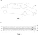
- FIG. 1 illustrates a vehicle 1000 provided in the embodiments of the disclosure.
- the vehicle 1000 includes a patterned glass 100 and a vehicle body 200, and the patterned glass 100 is connected to the vehicle body 200.
- the patterned glass 100 may be a sunroof glass, a front windshield glass, a rear windshield glass, or side window glass of the vehicle 1000.
- the specific position of the patterned glass 100 connected to the vehicle body 200 is not limited in the embodiments of the disclosure.
- the embodiments of the disclosure illustrate the vehicle 1000 with the patterned glass 100, but the patterned glass 100 can also be applied to buildings or other uses, and the embodiments of the disclosure do not limit the use of the patterned glass 100.
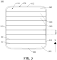
- the patterned glass 100 includes an outer glass 10, an inner glass 20, and a light control functional layer 30, a first conducting layer 40, a second conducting layer 50, and two adhesive layers 60.
- the light control functional layer 30, the first conducting layer 40, the second conducting layer 50, and the two adhesive layers 60 are arranged between the outer glass 10 and the inner glass 20.
- FIG. 2 is only to schematically describe the connection relationship between the outer glass 10, the inner glass 20, the light control functional layer 30, the first conducting layer 40, the second conducting layer 50, and the two adhesive layers 60, and not to limit the specific connection position, specific structure, and quantity of each device.
- the schematic structure in the embodiments of the disclosure does not constitute a specific limitation on the patterned glass 100.
- the patterned glass 100 may include more or fewer components than shown, or combine some components, or split some components, or have different component arrangements.
- the illustrated components can be implemented as hardware, software, or a combination of software and hardware.
- the light control functional layer 30 can be one of a polymer dispersed liquid crystal film (PDLC), a suspended particle device (SPD) film, or an electrochromism (EC) film.
- PDLC polymer dispersed liquid crystal film
- SPD suspended particle device
- EC electrochromism
- the first conducting layer 40 has multiple first separation lines 41
- the second conducting layer 50 has multiple second separation lines 51.
- the first separation lines 41 can divide the first conducting layer 40 into multiple sections, and the multiple sections of the first conducting layer 40 are electrically insulated from each other.
- the second separation lines 51 can divide the second conducting layer 50 into multiple sections, and the multiple sections of the second conducting layer 50 are electrically insulated from each other.
- Each section is independently connected to a voltage source so that they can be separately controlled. Therefore, different areas of the patterned glass 100 can be independently controlled, thereby displaying patterns of the patterned glass 100.
- the first conducting layer 40, the light control functional layer 30, and the second conducting layer 50 may cooperate to form a dimmable layer (not illustrated).
- the sections of the first conducting layer 40 and the sections of the second conducting layer 50 cooperate to conduct part of regions of the light control functional layer 30 to form a pattern. That is, the light control functional layer 30 is divided into multiple partitions according to shapes of the sections of the first conducting layer 40 and shapes of the sections of the second conducting layer 50.
- the shapes of the sections of the first conducting layer 40 may the same as the shapes of the sections of the second conducting layer 50.
- the dimmable layer may also include a first dielectric layer (not illustrated) and a second dielectric layer (not illustrated).
- the first dielectric layer may be disposed between the first conducting layer 40 and the adhesive layer 60 close to the outer glass 10.
- the second dielectric layer may be disposed between the second conducting layer 50 and the adhesive layer 60 close to the inner glass 20.
- Both the first dielectric layer and the second dielectric layer can be made of polyethylene terephthalate (PET).
- PET polyethylene terephthalate
- the first dielectric layer and the second dielectric layer can prevent internal components (i.e., the first conducting layer 40, the light control functional layer 30, and the second conducting layer 50) from directly contacting external structures, thereby protecting the internal components.
- the first conducting layer 40 is disposed between the light control functional layer 30 and the inner glass 20, and the second conducting layer 50 is disposed between the light control functional layer 30 and the outer glass 10.
- One adhesive layer 60 is disposed between the second conducting layer 50 and the inner glass 20, and another adhesive layer 60 is disposed between the first conducting layer 40 and the outer glass 10. That is, the inner glass 20, the one adhesive layer 60, the first conducting layer 40, the light control functional layer 30, the second conducting layer 50, the another adhesive layer 60, and the outer glass 10 are sequentially stacked.
- the outer glass 10 is a single layer of glass, of the patterned glass 100, facing the outside of the vehicle
- the inner glass 20 is a single layer of glass, of the patterned glass 100, facing the inside of the vehicle.
- a current may flow between the first conducting layer 40 and the second conducting layer 50, and the current may flow into the light control functional layer 30 through a current channel. Due to the photoelectric effect of the light control functional layer 30, the transparency of the patterned glass 100 can be changed. It may be noted that the first separation lines 41 and the second separation lines 51 can be straight lines and perpendicular to the light control functional layer 30. The first separation lines 41 and the second separation lines 51 can also be slightly curved. The disclosure does not limit the structure of the first separation lines 41 and the second separation lines 51.
- the positions of the first conducting layer 40 and the second conducting layer 50 in this embodiment are changed and thus different from that in the previous embodiments.
- the first conducting layer 40 is disposed between the light control functional layer 30 and the outer glass 10
- the second conducting layer 50 is disposed between the light control functional layer 30 and the inner glass 20.
- One adhesive layer 60 is disposed between the first conducting layer 40 and the inner glass 20, and another adhesive layer 60 is disposed between the second conducting layer 50 and the outer glass 10. That is, the outer glass 10, the one adhesive layer 60, the first conducting layer 40, the light control functional layer 30, the second conducting layer 50, the another adhesive layer 60, and the inner glass 20 are sequentially stacked.
- the patterned glass 100 may have a display region 110 and a non-display region 120.
- the display region 110 may be at the middle of the patterned glass 100, and the non-display region 120 may be at the edge of the patterned glass 100.
- the non-display region 120 is arranged around the periphery of the display region 110.
- the display region 110 is a region of the patterned glass 100 that can display patterns, while the non-display region 120 is a region of the patterned glass 100 that does not display patterns.
- the display region 110 may be a region on one side of the patterned glass 100, and the non-display region 120 may be a region on another side of the patterned glass 100.
- the entire patterned glass 100 may be set as the display region 110. The disclosure does not limit the positional relationship between the display region 110 and the non-display region 120.
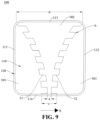
- the display region 110 has a first edge 111, a second edge 112, a third edge 113, and a fourth edge 114.
- the first edge 111 is opposite to the second edge 112
- the third edge 113 is opposite to the fourth edge 114
- the third edge 113 and the fourth edge 114 are arranged between the first edge 111 and the second edge 112.
- the layer structure of the patterned glass 100 in the display region 110 includes the light control functional layer 30.
- the layer structure of the patterned glass 100 in the non-display region 120 may not include the light control functional layer 30.
- the layer structure of the patterned glass 100 in the non-display region 120 may also include the light control functional layer 30, and the patterned glass 100 does not display patterns in the non-display region 120.
- the light control functional layer 30 has multiple partitions distributed in a first direction at intervals, where a direction from the first edge 111 towards the second edge 112 serves as the first direction, identified as X.
- Each partition has a first side 31 and a second side 32 opposite the first side 31, and the first side 31 and the second side 32 are arranged sequentially in the first direction.
- a distance between the first side 31 and the second side 32 at various positions in the same partition may be varied or unvaried.
- the minimum length of a spacing between the first side 31 and the second side 32 serves as distance a between the first side 31 and the second side 32, and the distance a is greater than or equal to 20 mm.
- FIG. 3 is a schematic structural view of the patterned glass 100 provided in the embodiments of the disclosure, with the light control functional layer 30 partitioned in a first manner
- FIG. 4 is a schematic structural view of the patterned glass 100 provided in the embodiments of the disclosure, with the light control functional layer 30 partitioned in a second manner
- FIG. 5 is a schematic structural view of the patterned glass 100 provided in the embodiments of the disclosure, with the light control functional layer 30 partitioned in a third manner
- FIG. 6 is a schematic structural view of the patterned glass 100 provided in the embodiments of the disclosure, with the light control functional layer partitioned in a fourth manner.
- One of the multiple partitions located at one end of the light control functional layer 30 serves as a first partition 301
- one of the multiple partitions located at another end of the light control functional layer 30 serves as a second partition 302
- regions located between the two ends of the light control functional layer 30 among the multiple partitions serve as multiple third partitions 303.
- One first partition 301, the multiple third partitions 303, and one second partition 302 are arranged sequentially in the first direction.
- the multiple third partitions 303 are the same in shape.
- the first side 31 and the second side 32 of the third partition 303 are arranged in parallel.
- both the first side 31 and the second side 32 of the third partition 303 are straight lines. Both the first side 31 and the second side 32 extend from the third edge 113 of the display region 110 to the fourth edge 114 of the display region 110. Distance a between the first side 31 and the second side 32 is greater than or equal to 20 mm.
- both the first side 31 and the second side 32 of the third partition 303 are arc-shaped. Both the first side 31 and the second side 32 extend from the third edge 113 of the display region to the fourth edge 114 of the display region. Distance a between the first side 31 and the second side 32 is greater than or equal to 20 mm.
- both the first side 31 and the second side 32 of the third partition 303 are zigzag-shaped.
- each two adjacent line segments are connected to each other by arc b with a radius of curvature greater than or equal to 1 mm.
- Distance a between the first side 31 and the second side 32 is greater than or equal to 20 mm.
- Both the first side 31 and the second side 32 extend from the third edge 113 of the display region to the fourth edge 114 of the display region.
- both the first side 31 and the second side 32 are rectangular wave-shaped, and distance a between the first side 31 and the second side 32 is greater than or equal to 20 mm.
- each two adjacent line segments are connected to each other by arc b with a radius of curvature greater than or equal to 1 mm.
- Both the first side 31 and the second side 32 extend from the third edge 113 of the display region to the fourth edge 114 of the display region.
- FIG. 7 is a schematic structural view of the patterned glass 100 provided in the embodiments of the disclosure, with the light control functional layer 30 partitioned in a fifth manner.
- One of the multiple partitions located at the first edge 111 serves as the first partition 301
- one of the multiple partitions located at the second edge 112 serves as the second partition 302
- regions located between the first edge 111 and the second edge 112 among the multiple partitions serve as one third partition 303.
- One first partition 301, the one third partition 303, and one second partition 302 are arranged sequentially in the first direction.
- the third partition in this embodiment is implemented as one third partition.
- the third partition 303 has three regions, that is, a first sub-partition 3031, a second sub-partition 3032, and a third sub-partition 3033.
- the first sub-partition 3031 and the second sub-partition 3032 are symmetrically arranged on both sides of the third sub-partition 3033.
- the first sub-partition 3031 has a first branch 3031a, a second branch 3031b, and a third branch 3031c.
- the first branch 3031a extends in the first direction
- the second branch 3031b and the third branch 3031c are symmetrically arranged on both sides of the first branch 3031a
- both one end of the second branch 3031b and one end of the third branch 3031c are connected to one end of the first branch 3031a.
- Another end of the second branch 3031b extends to the third edge 113
- another end of the third branch 3031c extends to the fourth edge 114.
- the first branch 3031a may be connected to the second branch 3031b by an arc with a radius of curvature greater than or equal to 1 mm.
- the first branch 3031a may be connected to the third branch 3031c by an arc with a radius of curvature greater than or equal to 1 mm.
- the shape of the second sub-partition 3032 is a mirror image of the shape of the first sub-partition 3031. Therefore, the shape of the second sub-partition 3032 can refer to the shape of the first sub-partition 3031, and will not be described herein in detail.
- FIG. 8 is a schematic structural view of the patterned glass 100 provided in the embodiments of the disclosure, with the light control functional layer 30 partitioned in a sixth manner.
- both the patterned glass 100 in the first possible embodiment and the patterned glass 100 in the second possible embodiment may be a sunroof glass.
- the patterned glass 100 in this embodiment may be a front windshield glass.
- the display region 110 of the patterned glass 100 may be located in the upper half of the front windshield glass of the vehicle 1000.
- the first edge 111 and the second edge 112 of the patterned glass 100 are located on the left and right sides of the front windshield glass, respectively.
- the patterned glass 100 in this embodiment includes one first partition 301, one third partition 303, and one second partition 302, and the one first partition 301, the one third partition 303, and the one second partition 302 are arranged sequentially in the first direction.
- the patterned glass 100 in this embodiment is different from the patterned glass 100 in the second possible embodiment as follows.
- each of the first partition 301, the second partition 302, and the third partition 303 is trapezoidal and has the first side 31, the second side 32, the third side 33, and the fourth side 34.
- the first side 31 is opposite to the second side 32
- the third side 33 is opposite to the fourth side 34
- both the third side 33 and the fourth side 34 are connected to the first side 31 and the second side 32. Both distance a between the first side 31 and the second side 32 and distance a between the third side 33 and the fourth side 34 are greater than or equal to 20 mm.
- the third partition 303 may be an inverted trapezoid.
- the first partition 301 and the second partition 302 are symmetrically arranged on both sides of the third partition 303.
- the third partition 303 can improve transparency under the action of electric current, making it easier for devices such as cameras or dashcams inside the vehicle to capture images outside the vehicle.
- FIG. 9 is a schematic structural view of the patterned glass 100 provided in the embodiments of the disclosure, with the light control functional layer 30 partitioned in a seventh manner.
- the patterned glass 100 in this embodiment includes one first partition 301, one third partition 303, and one second partition 302, and the one first partition 301, the one third partition 303, and the one second partition 302 are arranged sequentially in the first direction.
- the first partition 301 and the second partition 302 are symmetrically arranged on both sides of the third partition 303.
- the patterned glass 100 in FIG. 9 is different from the patterned glass 100 in the second possible embodiment as follows.
- both the first side 31 and the second side 32 of the third partition 303 are wavy, composed of multiple bent line segments.
- Both the first side 31 and the second side 32 of the third partition 303 extend from one end of the display region 110 close to the third edge 113 to another end of the display region 110 close to the fourth edge 114.
- a distance between one end of the first side 31 close to the third edge 113 and one end of the second side 32 close to the third edge 113 is first distance d
- a distance between another end of the first side 31 close to the fourth edge 114 and another end of the second side 32 close to the fourth edge 114 is second distance c
- first distance d is greater than second distance c
- distance a between the first side 31 and the second side 32 is greater than or equal to 20 mm.
- each two adjacent segments are connected to each other by arc b with a radius of curvature greater than or equal to 1mm.
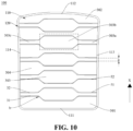
- FIG. 10 is a schematic structural view of the patterned glass 100 provided in the embodiments of the disclosure, with the light control functional layer 30 partitioned in an eighth manner.
- the patterned glass 100 in FIG. 10 is different from the patterned glass 100 in the first possible embodiment as follows.
- the patterned glass 100 in this embodiment has four partitions. Specifically, one of the multiple partitions located at the first edge 111 serves as the first partition 301, one of the multiple partitions located at the second edge 112 serves as the second partition 302, and regions located between the first edge 111 and the second edge 112 among the multiple partitions serve as multiple third partitions 303 and multiple fourth partitions 304.
- Each two adjacent third partitions 303 among the multiple third partitions 303 are spaced apart from each other by one fourth partition 304 and are symmetrically arranged on both sides of the one fourth partition 304.
- the third partition 303 has a first section 303a, a second section 303b, and a third section 303c arranged in sequence in a direction perpendicular to the first direction.
- the second section 303b is longer than both the first section 303a and the third section 303c in the first direction.
- the second section 303b may be octagonal.
- the first section 303a and the second section 303b are the same as each other in shape and are rectangular.
- the first section 303a and the third section 303c are located on the two opposite sides of the second section 303b, respectively.
- the fourth partition 304 may be hourglass-shaped and located between the two third partitions 303. An edge of the fourth partition 304 may be spaced apart from an edge of the third partitions 303.
- Each two adjacent segments of the second section 303b are connected to each other by an arc with a radius of curvature greater than or equal to 1 mm.
- the first section 303a is smoothly connected to the second section 303b by an arc with a radius of curvature greater than or equal to 1 mm.
- the third section 303c is smoothly connected to the second section 303b by an arc with a radius of curvature greater than or equal to 1 mm.
- the partitions of the patterned glass 100 are sequentially arranged in the first direction as follows.
- One first partition 301, one third partition 303, one fourth partition 304, one third partition 303, one fourth partition 304, one third partition 303, one fourth partition 304, one third partition 303, one fourth partition 304, one third partition 303, one fourth partition 304, one third partition 303, and one second partition 302 are sequentially arranged.
- Each partition has the first side 31 and the second side 32 opposite the first side 31, and distance a between the first side 31 and the second side 32 is greater than or equal to 20 mm.
- FIG. 11 is a schematic structural view of the patterned glass 100 provided in the embodiments of the disclosure, with the light control functional layer 30 partitioned in a ninth manner. Similar to the patterned glass 100 in the fifth possible embodiment, the patterned glass 100 in this embodiment also includes one first partition 301, one second partition 302, multiple third partitions 303, and multiple fourth partitions 304, and the position of each partition of the patterned glass 100 in this embodiment may be the same as the position of each partition in the fifth possible embodiment.
- the patterned glass 100 in FIG. 11 is different from the patterned glass 100 in the fifth possible embodiment as follows.
- the third partition 303 has a first sub-partition 3031, a second sub-partition 3032, and a third sub-partition 3033, where the first sub-partition 3031 and the second sub-partition 3032 are symmetrically arranged on both sides of the third sub-partition 3033.
- the first sub-partition 3031 has the first branch 3031a, the second branch 3031b, and the third branch 3031c.
- the first branch 3031a extends in the first direction.
- the second branch 3031b and the third branch 3031c are symmetrically arranged on both sides of the first branch 3031a. Both one end of the second branch 3031b and one end of the third branch 3031c are connected to one end of the first branch 3031a. Another end of the second branch 3031b extends to the third edge 113, and another end of the third branch 3031c extends to the fourth edge 114.
- the first branch 3031a is connected to the second branch 3031b by an arc with a radius of curvature greater than or equal to 1 mm.
- the first branch 3031a is connected to the third branch 3031c by an arc with a radius of curvature greater than or equal to 1 mm.
- the shape of the second sub-partition 3032 is a mirror image of the shape of the first sub-partition 3031. Therefore, the shape of the second sub-partition 3032 can refer to the shape of the first sub-partition 3031, and will not be described herein in detail.
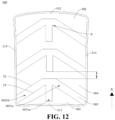
- FIG. 12 is a schematic structural view of the patterned glass 100 provided in the embodiments of the disclosure, with the light control functional layer 30 partitioned in a tenth manner.
- the patterned glass 100 in this embodiment also includes one first partition 301, one second partition 302, multiple third partitions 303, and multiple fourth partitions 304, and the position of each partition of the patterned glass 100 in this embodiment may be the same as the position of each partition of the patterned glass 100 in the fifth possible embodiment.
- the patterned glass 100 in FIG. 12 is different from the patterned glass 100 in the fifth possible embodiment as follows.
- the third partition 303 has the first branch 3031a, the second branch 3031b, and the third branch 3031c.
- the first branch 3031a extends in the first direction
- the second branch 3031b and the third branch 3031c are symmetrically arranged on both sides of the first branch 3031a.
- Both one end of the second branch 3031b and one end of the third branch 3031c are connected to one end of the first branch 3031a.
- Another end of the second branch 3031b extends to the third edge 113
- another end of the third branch 3031c extends to the fourth edge 114.
- the first branch 3031a is connected to the second branch 3031b by an arc with a radius of curvature greater than or equal to 1 mm.
- the first branch 3031a is connected to the third branch 3031c by an arc with a radius of curvature greater than or equal to 1 mm.
Landscapes
- Physics & Mathematics (AREA)
- Nonlinear Science (AREA)
- Chemical & Material Sciences (AREA)
- Crystallography & Structural Chemistry (AREA)
- Optics & Photonics (AREA)
- General Physics & Mathematics (AREA)
- Engineering & Computer Science (AREA)
- Mechanical Engineering (AREA)
- Mathematical Physics (AREA)
- Joining Of Glass To Other Materials (AREA)
- Devices For Indicating Variable Information By Combining Individual Elements (AREA)
- Liquid Crystal (AREA)
- Electrochromic Elements, Electrophoresis, Or Variable Reflection Or Absorption Elements (AREA)
Abstract
Description
- The disclosure relates to the field of glass technology, and in particular, to a patterned glass and a vehicle.
- Dimmable glass can switch between transparent and opaque states through various methods such as electric control, temperature control, light control, and pressure control. Due to various limitations, almost all mass-produced dimmable glass on the market is electrically controlled dimmable glass. By controlling partitions of the dimmable glass, different patterns can be displayed. However, the current partitioned dimmable glass is prone to uneven patterned-glass dimming due to unreasonable pattern settings.
- Embodiments of the disclosure provide a patterned glass and a vehicle, which are capable of optimizing the display uniformity of patterns of a partitioned dimmable patterned glass and enhancing the user experience.
- In a first aspect, a patterned glass is provided by the disclosure. The patterned glass includes a display region having a first edge and a second edge opposite the first edge. A direction from the first edge towards the second edge serves as a first direction. The patterned glass further includes an outer glass, an inner glass, and a light control functional layer disposed between the outer glass and the inner glass. The light control functional layer has multiple partitions distributed in the first direction at intervals. Each of the multiple partitions has a first side and a second side opposite the first side, the first side and the second side are sequentially distributed in the first direction, and a distance between the first side and the second side is greater than or equal to 20 mm.
- In a possible embodiment, each of the multiple partitions has multiple corners, where a radius of curvature of each of the multiple corners is greater than or equal to 1 mm.
- In a possible embodiment, the first side is a straight line or a curve.
- In a possible embodiment, one of the multiple partitions located at the first edge serves as a first partition, one of the multiple partitions located at the second edge serves as a second partition, and at least one of the multiple partitions located between the first edge and the second edge serves as at least one third partition. The first partition, the at least one third partition, and the second partition are arranged at intervals in the first direction.
- In a possible embodiment, the at least one third partition is implemented as multiple third partitions, where the multiple third partitions are arranged at intervals and are the same in shape.
- In a possible embodiment, each of the at least one third partition has a first sub-partition, a second sub-partition, and a third sub-partition, where the first sub-partition and the second sub-partition are symmetrically arranged on both sides of the third sub-partition.
- In a possible embodiment, one of the multiple partitions located at the first edge serves as a first partition, one of the multiple partitions located at the second edge serves as a second partition, and regions located between the first edge and the second edge among the multiple partitions serve as multiple third partitions and at least one fourth partition, where each adjacent two third partitions among the multiple third partitions are spaced apart from each other by one fourth partition and are symmetrically arranged on both sides of the one fourth partition.
- In a possible embodiment, each of the multiple third partitions has a first sub-partition, a second sub-partition, and a third sub-partition, where the first sub-partition and the second sub-partition are symmetrically arranged on both sides of the third sub-partition.
- In a possible embodiment, the display region further has a third edge and a fourth edge opposite the third edge, where the third edge and the fourth edge are located between the first edge and the second edge. The first sub-partition has a first branch, a second branch, and a third branch, where the first branch extends in the first direction, the second branch and the third branch are symmetrically arranged on both sides of the first branch, both one end of the second branch and one end of the third branch are connected to one end of the first branch, another end of the second branch extends to the third edge, and another end of the third branch extends to the fourth edge.
- In a possible embodiment, the display region further has a third edge and a fourth edge opposite the third edge, where the third edge and the fourth edge are located between the first edge and the second edge. Each of the multiple third partitions has a first branch, a second branch, and a third branch, where the first branch extends in the first direction, the second branch and the third branch are symmetrically arranged on both sides of the first branch, both one end of the second branch and one end of the third branch are connected to one end of the first branch, another end of the second branch extends to the third edge, and another end of the third branch extends to the fourth edge.
- In a possible embodiment, each of the multiple third partitions has a first section, a second section, and a third section arranged in sequence in a direction perpendicular to the first direction, where the second section is longer than both the first section and the third section in the first direction.
- In a possible embodiment, the patterned glass further includes a first conducting layer and a second conducting layer. The first conducting layer is disposed between the light control functional layer and the inner glass, and the second conducting layer is disposed between the light control functional layer and the outer glass. Alternatively, the first conducting layer is disposed between the light control functional layer and the outer glass, and the second conducting layer is disposed between the light control functional layer and the inner glass.
- In a possible embodiment, the patterned glass further includes two adhesive layers. One of the two adhesive layers is disposed between the first conducting layer and the inner glass, and another one of the two adhesive layers is disposed between the second conducting layer and the outer glass. Alternatively, one of the two adhesive layers is disposed between the second conducting layer and the inner glass, and another one of the two adhesive layers is disposed between the first conducting layer and the outer glass.
- In a second aspect, a vehicle is further provided in the disclosure. The vehicle includes a vehicle body and the above-mentioned patterned glass. The patterned glass is connected to the vehicle body.
- To describe the solutions in the disclosure more clearly, the following briefly introduces the accompanying drawings required for describing the embodiments. Apparently, the accompanying drawings in the following description show merely some embodiments of the disclosure, and those of ordinary skill in the art may still derive other accompanying drawings from these accompanying drawings without creative efforts.
-
FIG. 1 is a vehicle provided in embodiments of the disclosure. -
FIG. 2 is a cross-sectional schematic view of a patterned glass provided in embodiments of the disclosure. -
FIG. 3 is a schematic structural view of the patterned glass inFIG. 2 , with a light control functional layer partitioned in a first manner. -
FIG. 4 is a schematic structural view of the patterned glass inFIG. 2 , with a light control functional layer partitioned in a second manner. -
FIG. 5 is a schematic structural view of the patterned glass inFIG. 2 , with a light control functional layer partitioned in a third manner. -
FIG. 6 is a schematic structural view of the patterned glass inFIG. 2 , with a light control functional layer partitioned in a fourth manner. -
FIG. 7 is a schematic structural view of the patterned glass inFIG. 2 , with a light control functional layer partitioned in a fifth manner. -
FIG. 8 is a schematic structural view of the patterned glass inFIG. 2 , with a light control functional layer partitioned in a sixth manner. -
FIG. 9 is a schematic structural view of the patterned glass inFIG. 2 , with a light control functional layer partitioned in a seventh manner. -
FIG. 10 is a schematic structural view of the patterned glass inFIG. 2 , with a light control functional layer partitioned in an eighth manner. -
FIG. 11 is a schematic structural view of the patterned glass inFIG. 2 , with a light control functional layer partitioned in a ninth manner. -
FIG. 12 is a schematic structural view of the patterned glass inFIG. 2 , with a light control functional layer partitioned in a tenth manner. - For the sake of convenience, the terms related to embodiments of the disclosure are explained first.
- Terms "a plurality of" and "multiple" mean that the number is two or more.
- Terms "connect" may be understood in a broad sense. For example, A and B are connected, which can be directly connected or indirectly connected through an intermediate medium.
- Hereinafter, specific embodiments of the disclosure will be clearly described in conjunction with the accompanying drawings.
- Dimmable glass can switch between transparent and opaque states through various methods such as electric control, temperature control, light control, and pressure control. Almost all mass-produced dimmable glass on the market is electrically controlled dimmable glass. By controlling partitions of the dimmable glass, different patterns can be displayed. The current partitioned dimmable glass is prone to uneven patterned-glass dimming due to unreasonable pattern settings. Specifically, if a channel width of one of partitions is insufficient, the single-channel dimming of an independent partition will have a voltage drop, causing uneven dimming.
- In view of above, the embodiments of the disclosure provide a patterned glass and a vehicle, which are capable of optimizing the display uniformity of patterns of a partitioned dimmable patterned glass and enhancing the user experience.
- Referring to
FIG. 1, FIG. 1 illustrates avehicle 1000 provided in the embodiments of the disclosure. Thevehicle 1000 includes a patternedglass 100 and avehicle body 200, and the patternedglass 100 is connected to thevehicle body 200. Exemplarily, the patternedglass 100 may be a sunroof glass, a front windshield glass, a rear windshield glass, or side window glass of thevehicle 1000. The specific position of the patternedglass 100 connected to thevehicle body 200 is not limited in the embodiments of the disclosure. - It may be understood that the embodiments of the disclosure illustrate the
vehicle 1000 with the patternedglass 100, but the patternedglass 100 can also be applied to buildings or other uses, and the embodiments of the disclosure do not limit the use of the patternedglass 100. - Referring to
FIG. 2 , which is a schematic cross-sectional view of the patternedglass 100 provided in the embodiments of the disclosure. The patternedglass 100 includes anouter glass 10, aninner glass 20, and a light controlfunctional layer 30, afirst conducting layer 40, asecond conducting layer 50, and twoadhesive layers 60. The light controlfunctional layer 30, thefirst conducting layer 40, thesecond conducting layer 50, and the twoadhesive layers 60 are arranged between theouter glass 10 and theinner glass 20. - It may be noted that the purpose of
FIG. 2 is only to schematically describe the connection relationship between theouter glass 10, theinner glass 20, the light controlfunctional layer 30, thefirst conducting layer 40, thesecond conducting layer 50, and the twoadhesive layers 60, and not to limit the specific connection position, specific structure, and quantity of each device. The schematic structure in the embodiments of the disclosure does not constitute a specific limitation on the patternedglass 100. In other embodiments of the disclosure, the patternedglass 100 may include more or fewer components than shown, or combine some components, or split some components, or have different component arrangements. The illustrated components can be implemented as hardware, software, or a combination of software and hardware. - Exemplarily, the light control
functional layer 30 can be one of a polymer dispersed liquid crystal film (PDLC), a suspended particle device (SPD) film, or an electrochromism (EC) film. - The
first conducting layer 40 has multiplefirst separation lines 41, and thesecond conducting layer 50 has multiple second separation lines 51. Thefirst separation lines 41 can divide thefirst conducting layer 40 into multiple sections, and the multiple sections of thefirst conducting layer 40 are electrically insulated from each other. Thesecond separation lines 51 can divide thesecond conducting layer 50 into multiple sections, and the multiple sections of thesecond conducting layer 50 are electrically insulated from each other. Each section is independently connected to a voltage source so that they can be separately controlled. Therefore, different areas of the patternedglass 100 can be independently controlled, thereby displaying patterns of the patternedglass 100. Thefirst conducting layer 40, the light controlfunctional layer 30, and thesecond conducting layer 50 may cooperate to form a dimmable layer (not illustrated). The sections of thefirst conducting layer 40 and the sections of thesecond conducting layer 50 cooperate to conduct part of regions of the light controlfunctional layer 30 to form a pattern. That is, the light controlfunctional layer 30 is divided into multiple partitions according to shapes of the sections of thefirst conducting layer 40 and shapes of the sections of thesecond conducting layer 50. The shapes of the sections of thefirst conducting layer 40 may the same as the shapes of the sections of thesecond conducting layer 50. - The dimmable layer may also include a first dielectric layer (not illustrated) and a second dielectric layer (not illustrated). The first dielectric layer may be disposed between the
first conducting layer 40 and theadhesive layer 60 close to theouter glass 10. The second dielectric layer may be disposed between thesecond conducting layer 50 and theadhesive layer 60 close to theinner glass 20. Both the first dielectric layer and the second dielectric layer can be made of polyethylene terephthalate (PET). The first dielectric layer and the second dielectric layer can prevent internal components (i.e., thefirst conducting layer 40, the light controlfunctional layer 30, and the second conducting layer 50) from directly contacting external structures, thereby protecting the internal components. - In one possible embodiment, the
first conducting layer 40 is disposed between the light controlfunctional layer 30 and theinner glass 20, and thesecond conducting layer 50 is disposed between the light controlfunctional layer 30 and theouter glass 10. Oneadhesive layer 60 is disposed between thesecond conducting layer 50 and theinner glass 20, and anotheradhesive layer 60 is disposed between thefirst conducting layer 40 and theouter glass 10. That is, theinner glass 20, the oneadhesive layer 60, thefirst conducting layer 40, the light controlfunctional layer 30, thesecond conducting layer 50, the anotheradhesive layer 60, and theouter glass 10 are sequentially stacked. Theouter glass 10 is a single layer of glass, of the patternedglass 100, facing the outside of the vehicle, and theinner glass 20 is a single layer of glass, of the patternedglass 100, facing the inside of the vehicle. A current may flow between thefirst conducting layer 40 and thesecond conducting layer 50, and the current may flow into the light controlfunctional layer 30 through a current channel. Due to the photoelectric effect of the light controlfunctional layer 30, the transparency of the patternedglass 100 can be changed. It may be noted that thefirst separation lines 41 and thesecond separation lines 51 can be straight lines and perpendicular to the light controlfunctional layer 30. Thefirst separation lines 41 and thesecond separation lines 51 can also be slightly curved. The disclosure does not limit the structure of thefirst separation lines 41 and the second separation lines 51. - In another possible embodiment, the positions of the
first conducting layer 40 and thesecond conducting layer 50 in this embodiment are changed and thus different from that in the previous embodiments. Thefirst conducting layer 40 is disposed between the light controlfunctional layer 30 and theouter glass 10, and thesecond conducting layer 50 is disposed between the light controlfunctional layer 30 and theinner glass 20. Oneadhesive layer 60 is disposed between thefirst conducting layer 40 and theinner glass 20, and anotheradhesive layer 60 is disposed between thesecond conducting layer 50 and theouter glass 10. That is, theouter glass 10, the oneadhesive layer 60, thefirst conducting layer 40, the light controlfunctional layer 30, thesecond conducting layer 50, the anotheradhesive layer 60, and theinner glass 20 are sequentially stacked. - Referring to
FIG. 3 , which is a schematic structural view of the patternedglass 100 inFIG. 2 , with the light controlfunctional layer 30 partitioned in a first manner. The patternedglass 100 may have adisplay region 110 and anon-display region 120. Thedisplay region 110 may be at the middle of the patternedglass 100, and thenon-display region 120 may be at the edge of the patternedglass 100. Thenon-display region 120 is arranged around the periphery of thedisplay region 110. Thedisplay region 110 is a region of the patternedglass 100 that can display patterns, while thenon-display region 120 is a region of the patternedglass 100 that does not display patterns. Alternatively, thedisplay region 110 may be a region on one side of the patternedglass 100, and thenon-display region 120 may be a region on another side of the patternedglass 100. The entire patternedglass 100 may be set as thedisplay region 110. The disclosure does not limit the positional relationship between thedisplay region 110 and thenon-display region 120. - The
display region 110 has afirst edge 111, asecond edge 112, athird edge 113, and afourth edge 114. Thefirst edge 111 is opposite to thesecond edge 112, thethird edge 113 is opposite to thefourth edge 114, and thethird edge 113 and thefourth edge 114 are arranged between thefirst edge 111 and thesecond edge 112. It may be noted that the layer structure of the patternedglass 100 in thedisplay region 110 includes the light controlfunctional layer 30. The layer structure of the patternedglass 100 in thenon-display region 120 may not include the light controlfunctional layer 30. Alternatively, the layer structure of the patternedglass 100 in thenon-display region 120 may also include the light controlfunctional layer 30, and the patternedglass 100 does not display patterns in thenon-display region 120. - The light control
functional layer 30 has multiple partitions distributed in a first direction at intervals, where a direction from thefirst edge 111 towards thesecond edge 112 serves as the first direction, identified as X. Each partition has afirst side 31 and asecond side 32 opposite thefirst side 31, and thefirst side 31 and thesecond side 32 are arranged sequentially in the first direction. A distance between thefirst side 31 and thesecond side 32 at various positions in the same partition may be varied or unvaried. In a case where the distance between thefirst side 31 and thesecond side 32 at various positions in the same partition is varied, the minimum length of a spacing between thefirst side 31 and thesecond side 32 serves as distance a between thefirst side 31 and thesecond side 32, and the distance a is greater than or equal to 20 mm. - In a first possible embodiment, refer to
FIGS. 3 ,4 ,5 , and6 .FIG. 3 is a schematic structural view of the patternedglass 100 provided in the embodiments of the disclosure, with the light controlfunctional layer 30 partitioned in a first manner,FIG. 4 is a schematic structural view of the patternedglass 100 provided in the embodiments of the disclosure, with the light controlfunctional layer 30 partitioned in a second manner,FIG. 5 is a schematic structural view of the patternedglass 100 provided in the embodiments of the disclosure, with the light controlfunctional layer 30 partitioned in a third manner, andFIG. 6 is a schematic structural view of the patternedglass 100 provided in the embodiments of the disclosure, with the light control functional layer partitioned in a fourth manner. - One of the multiple partitions located at one end of the light control
functional layer 30 serves as afirst partition 301, one of the multiple partitions located at another end of the light controlfunctional layer 30 serves as asecond partition 302, and regions located between the two ends of the light controlfunctional layer 30 among the multiple partitions serve as multiplethird partitions 303. Onefirst partition 301, the multiplethird partitions 303, and onesecond partition 302 are arranged sequentially in the first direction. The multiplethird partitions 303 are the same in shape. Thefirst side 31 and thesecond side 32 of thethird partition 303 are arranged in parallel. - As illustrated in
FIG. 3 , in the first possible embodiment, both thefirst side 31 and thesecond side 32 of thethird partition 303 are straight lines. Both thefirst side 31 and thesecond side 32 extend from thethird edge 113 of thedisplay region 110 to thefourth edge 114 of thedisplay region 110. Distance a between thefirst side 31 and thesecond side 32 is greater than or equal to 20 mm. - As illustrated in
FIG. 4 , in a second possible embodiment, both thefirst side 31 and thesecond side 32 of thethird partition 303 are arc-shaped. Both thefirst side 31 and thesecond side 32 extend from thethird edge 113 of the display region to thefourth edge 114 of the display region. Distance a between thefirst side 31 and thesecond side 32 is greater than or equal to 20 mm. - As illustrated in
FIG. 5 , in a third possible embodiment, both thefirst side 31 and thesecond side 32 of thethird partition 303 are zigzag-shaped. In each of thefirst side 31 and thesecond side 32, each two adjacent line segments are connected to each other by arc b with a radius of curvature greater than or equal to 1 mm. Distance a between thefirst side 31 and thesecond side 32 is greater than or equal to 20 mm. Both thefirst side 31 and thesecond side 32 extend from thethird edge 113 of the display region to thefourth edge 114 of the display region. - As illustrated in
FIG. 6 , in a fourth possible embodiment, both thefirst side 31 and thesecond side 32 are rectangular wave-shaped, and distance a between thefirst side 31 and thesecond side 32 is greater than or equal to 20 mm. In each of thefirst side 31 and thesecond side 32, each two adjacent line segments are connected to each other by arc b with a radius of curvature greater than or equal to 1 mm. Both thefirst side 31 and thesecond side 32 extend from thethird edge 113 of the display region to thefourth edge 114 of the display region. - In the second possible embodiment, refer to
FIG. 7 , which is a schematic structural view of the patternedglass 100 provided in the embodiments of the disclosure, with the light controlfunctional layer 30 partitioned in a fifth manner. - One of the multiple partitions located at the
first edge 111 serves as thefirst partition 301, one of the multiple partitions located at thesecond edge 112 serves as thesecond partition 302, and regions located between thefirst edge 111 and thesecond edge 112 among the multiple partitions serve as onethird partition 303. Onefirst partition 301, the onethird partition 303, and onesecond partition 302 are arranged sequentially in the first direction. - Different from the first embodiment, the third partition in this embodiment is implemented as one third partition. The
third partition 303 has three regions, that is, afirst sub-partition 3031, asecond sub-partition 3032, and athird sub-partition 3033. Thefirst sub-partition 3031 and thesecond sub-partition 3032 are symmetrically arranged on both sides of thethird sub-partition 3033. - The
first sub-partition 3031 has afirst branch 3031a, asecond branch 3031b, and athird branch 3031c. Thefirst branch 3031a extends in the first direction, thesecond branch 3031b and thethird branch 3031c are symmetrically arranged on both sides of thefirst branch 3031a, both one end of thesecond branch 3031b and one end of thethird branch 3031c are connected to one end of thefirst branch 3031a. Another end of thesecond branch 3031b extends to thethird edge 113, and another end of thethird branch 3031c extends to thefourth edge 114. Thefirst branch 3031a may be connected to thesecond branch 3031b by an arc with a radius of curvature greater than or equal to 1 mm. Thefirst branch 3031a may be connected to thethird branch 3031c by an arc with a radius of curvature greater than or equal to 1 mm. - Since the
second sub-partition 3032 is symmetrical to thefirst sub-partition 3031 about thethird sub-partition 3033, the shape of thesecond sub-partition 3032 is a mirror image of the shape of thefirst sub-partition 3031. Therefore, the shape of thesecond sub-partition 3032 can refer to the shape of thefirst sub-partition 3031, and will not be described herein in detail. - In the third possible embodiment, refer to
FIG. 8 , which is a schematic structural view of the patternedglass 100 provided in the embodiments of the disclosure, with the light controlfunctional layer 30 partitioned in a sixth manner. - It may be understood that both the patterned
glass 100 in the first possible embodiment and the patternedglass 100 in the second possible embodiment may be a sunroof glass. The patternedglass 100 in this embodiment may be a front windshield glass. Thedisplay region 110 of the patternedglass 100 may be located in the upper half of the front windshield glass of thevehicle 1000. Thefirst edge 111 and thesecond edge 112 of the patternedglass 100 are located on the left and right sides of the front windshield glass, respectively. Similar to the patternedglass 100 in the second possible embodiment, the patternedglass 100 in this embodiment includes onefirst partition 301, onethird partition 303, and onesecond partition 302, and the onefirst partition 301, the onethird partition 303, and the onesecond partition 302 are arranged sequentially in the first direction. - The patterned
glass 100 in this embodiment is different from the patternedglass 100 in the second possible embodiment as follows. In this embodiment, each of thefirst partition 301, thesecond partition 302, and thethird partition 303 is trapezoidal and has thefirst side 31, thesecond side 32, thethird side 33, and thefourth side 34. Thefirst side 31 is opposite to thesecond side 32, thethird side 33 is opposite to thefourth side 34, and both thethird side 33 and thefourth side 34 are connected to thefirst side 31 and thesecond side 32. Both distance a between thefirst side 31 and thesecond side 32 and distance a between thethird side 33 and thefourth side 34 are greater than or equal to 20 mm. Thethird partition 303 may be an inverted trapezoid. In this embodiment, thefirst partition 301 and thesecond partition 302 are symmetrically arranged on both sides of thethird partition 303. Thethird partition 303 can improve transparency under the action of electric current, making it easier for devices such as cameras or dashcams inside the vehicle to capture images outside the vehicle. - In the fourth possible embodiment, refer to
FIG. 9 , which is a schematic structural view of the patternedglass 100 provided in the embodiments of the disclosure, with the light controlfunctional layer 30 partitioned in a seventh manner. Similar to the patternedglass 100 in the second possible embodiment, the patternedglass 100 in this embodiment includes onefirst partition 301, onethird partition 303, and onesecond partition 302, and the onefirst partition 301, the onethird partition 303, and the onesecond partition 302 are arranged sequentially in the first direction. - The
first partition 301 and thesecond partition 302 are symmetrically arranged on both sides of thethird partition 303. The patternedglass 100 inFIG. 9 is different from the patternedglass 100 in the second possible embodiment as follows. In this embodiment, both thefirst side 31 and thesecond side 32 of thethird partition 303 are wavy, composed of multiple bent line segments. Both thefirst side 31 and thesecond side 32 of thethird partition 303 extend from one end of thedisplay region 110 close to thethird edge 113 to another end of thedisplay region 110 close to thefourth edge 114. A distance between one end of thefirst side 31 close to thethird edge 113 and one end of thesecond side 32 close to thethird edge 113 is first distance d, and a distance between another end of thefirst side 31 close to thefourth edge 114 and another end of thesecond side 32 close to thefourth edge 114 is second distance c, where first distance d is greater than second distance c, and distance a between thefirst side 31 and thesecond side 32 is greater than or equal to 20 mm. In each of thefirst side 31 and thesecond side 32, each two adjacent segments are connected to each other by arc b with a radius of curvature greater than or equal to 1mm. - In a fifth possible embodiment, refer to
FIG. 10 , which is a schematic structural view of the patternedglass 100 provided in the embodiments of the disclosure, with the light controlfunctional layer 30 partitioned in an eighth manner. The patternedglass 100 inFIG. 10 is different from the patternedglass 100 in the first possible embodiment as follows. The patternedglass 100 in this embodiment has four partitions. Specifically, one of the multiple partitions located at thefirst edge 111 serves as thefirst partition 301, one of the multiple partitions located at thesecond edge 112 serves as thesecond partition 302, and regions located between thefirst edge 111 and thesecond edge 112 among the multiple partitions serve as multiplethird partitions 303 and multiplefourth partitions 304. Each two adjacentthird partitions 303 among the multiplethird partitions 303 are spaced apart from each other by onefourth partition 304 and are symmetrically arranged on both sides of the onefourth partition 304. - The
third partition 303 has afirst section 303a, asecond section 303b, and athird section 303c arranged in sequence in a direction perpendicular to the first direction. Thesecond section 303b is longer than both thefirst section 303a and thethird section 303c in the first direction. Thesecond section 303b may be octagonal. Thefirst section 303a and thesecond section 303b are the same as each other in shape and are rectangular. Thefirst section 303a and thethird section 303c are located on the two opposite sides of thesecond section 303b, respectively. Thefourth partition 304 may be hourglass-shaped and located between the twothird partitions 303. An edge of thefourth partition 304 may be spaced apart from an edge of thethird partitions 303. - Each two adjacent segments of the
second section 303b are connected to each other by an arc with a radius of curvature greater than or equal to 1 mm. Thefirst section 303a is smoothly connected to thesecond section 303b by an arc with a radius of curvature greater than or equal to 1 mm. Thethird section 303c is smoothly connected to thesecond section 303b by an arc with a radius of curvature greater than or equal to 1 mm. - In this embodiment, there are four
third partitions 303 and threefourth partitions 304. Thus, in this embodiment, the partitions of the patternedglass 100 are sequentially arranged in the first direction as follows. Onefirst partition 301, onethird partition 303, onefourth partition 304, onethird partition 303, onefourth partition 304, onethird partition 303, onefourth partition 304, onethird partition 303, onefourth partition 304, onethird partition 303, and onesecond partition 302 are sequentially arranged. Each partition has thefirst side 31 and thesecond side 32 opposite thefirst side 31, and distance a between thefirst side 31 and thesecond side 32 is greater than or equal to 20 mm. - In a sixth possible embodiment, refer to
FIG. 11 , which is a schematic structural view of the patternedglass 100 provided in the embodiments of the disclosure, with the light controlfunctional layer 30 partitioned in a ninth manner. Similar to the patternedglass 100 in the fifth possible embodiment, the patternedglass 100 in this embodiment also includes onefirst partition 301, onesecond partition 302, multiplethird partitions 303, and multiplefourth partitions 304, and the position of each partition of the patternedglass 100 in this embodiment may be the same as the position of each partition in the fifth possible embodiment. The patternedglass 100 inFIG. 11 is different from the patternedglass 100 in the fifth possible embodiment as follows. In the patternedglass 100 in this embodiment, thethird partition 303 has afirst sub-partition 3031, asecond sub-partition 3032, and athird sub-partition 3033, where thefirst sub-partition 3031 and thesecond sub-partition 3032 are symmetrically arranged on both sides of thethird sub-partition 3033. - The
first sub-partition 3031 has thefirst branch 3031a, thesecond branch 3031b, and thethird branch 3031c. Thefirst branch 3031a extends in the first direction. Thesecond branch 3031b and thethird branch 3031c are symmetrically arranged on both sides of thefirst branch 3031a. Both one end of thesecond branch 3031b and one end of thethird branch 3031c are connected to one end of thefirst branch 3031a. Another end of thesecond branch 3031b extends to thethird edge 113, and another end of thethird branch 3031c extends to thefourth edge 114. Thefirst branch 3031a is connected to thesecond branch 3031b by an arc with a radius of curvature greater than or equal to 1 mm. Thefirst branch 3031a is connected to thethird branch 3031c by an arc with a radius of curvature greater than or equal to 1 mm. - Since the
second sub-partition 3032 is symmetrical to thefirst sub-partition 3031 about thethird sub-partition 3033, the shape of thesecond sub-partition 3032 is a mirror image of the shape of thefirst sub-partition 3031. Therefore, the shape of thesecond sub-partition 3032 can refer to the shape of thefirst sub-partition 3031, and will not be described herein in detail. For example, there may be threethird partitions 303, where onefourth partition 304 is disposed between each two adjacentthird partitions 303. Alternatively, there may be fourthird partitions 303, where onefourth partition 304 is disposed between each two adjacentthird partitions 303. In this embodiment, there may be multiplethird partitions 303, and the number ofthird partitions 303 is not limited in this embodiment. - In a seventh possible embodiment, refer to
FIG. 12 , which is a schematic structural view of the patternedglass 100 provided in the embodiments of the disclosure, with the light controlfunctional layer 30 partitioned in a tenth manner. - Similar to the patterned
glass 100 in the fifth possible embodiment, the patternedglass 100 in this embodiment also includes onefirst partition 301, onesecond partition 302, multiplethird partitions 303, and multiplefourth partitions 304, and the position of each partition of the patternedglass 100 in this embodiment may be the same as the position of each partition of the patternedglass 100 in the fifth possible embodiment. - The patterned
glass 100 inFIG. 12 is different from the patternedglass 100 in the fifth possible embodiment as follows. In the patternedglass 100 in this embodiment, thethird partition 303 has thefirst branch 3031a, thesecond branch 3031b, and thethird branch 3031c. Thefirst branch 3031a extends in the first direction, and thesecond branch 3031b and thethird branch 3031c are symmetrically arranged on both sides of thefirst branch 3031a. Both one end of thesecond branch 3031b and one end of thethird branch 3031c are connected to one end of thefirst branch 3031a. Another end of thesecond branch 3031b extends to thethird edge 113, and another end of thethird branch 3031c extends to thefourth edge 114. Thefirst branch 3031a is connected to thesecond branch 3031b by an arc with a radius of curvature greater than or equal to 1 mm. Thefirst branch 3031a is connected to thethird branch 3031c by an arc with a radius of curvature greater than or equal to 1 mm. - The embodiments of the disclosure are described in detail above, specific examples are used herein to describe the principle and implementation manners of the disclosure. The description of the above embodiments is merely used to help understand the method and the core idea of the disclosure. Meanwhile, those skilled in the art may make modifications to the specific implementation manners and the application scope according to the idea of the disclosure. In summary, the contents of the specification should not be construed as limiting the disclosure.
Claims (14)
- A patterned glass, wherein the patterned glass comprises a display region having a first edge and a second edge opposite the first edge, wherein a direction from the first edge towards the second edge serves as a first direction; and wherein the patterned glass further comprises an outer glass, an inner glass, and a light control functional layer disposed between the outer glass and the inner glass, wherein the light control functional layer has a plurality of partitions distributed in the first direction at intervals, wherein each of the plurality of partitions has a first side and a second side opposite the first side, the first side and the second side are sequentially distributed in the first direction, and a distance between the first side and the second side is greater than or equal to 20 mm.
- The patterned glass according to claim 1, wherein each of the plurality of partitions has a plurality of corners, wherein a radius of curvature of each of the plurality of corners is greater than or equal to 1 mm.
- The patterned glass according to claim 1, wherein the first side is a straight line or a curve.
- The patterned glass according to any one of claims 1 to 3, wherein one of the plurality of partitions located at the first edge serves as a first partition, one of the plurality of partitions located at the second edge serves as a second partition, and at least one of the plurality of partitions located between the first edge and the second edge serves as at least one third partition, wherein the first partition, the at least one third partition, and the second partition are arranged at intervals in the first direction.
- The patterned glass according to claim 4, wherein the at least one third partition is implemented as a plurality of third partitions, wherein the plurality of third partitions are arranged at intervals and are the same in shape.
- The patterned glass according to claim 4, wherein each of the at least one third partition has a first sub-partition, a second sub-partition, and a third sub-partition, wherein the first sub-partition and the second sub-partition are symmetrically arranged on both sides of the third sub-partition.
- The patterned glass according to any one of claims 1 to 3, wherein one of the plurality of partitions located at the first edge serves as a first partition, one of the plurality of partitions located at the second edge serves as a second partition, and regions located between the first edge and the second edge among the plurality of partitions serve as a plurality of third partitions and at least one fourth partition, wherein each adjacent two third partitions among the plurality of third partitions are spaced apart from each other by one fourth partition and are symmetrically arranged on both sides of the one fourth partition.
- The patterned glass according to claim 7, wherein each of the plurality of third partitions has a first sub-partition, a second sub-partition, and a third sub-partition, wherein the first sub-partition and the second sub-partition are symmetrically arranged on both sides of the third sub-partition.
- The patterned glass according to claim 6 or 8, whereinthe display region further has a third edge and a fourth edge opposite the third edge, wherein the third edge and the fourth edge are located between the first edge and the second edge; andthe first sub-partition has a first branch, a second branch, and a third branch, wherein the first branch extends in the first direction, the second branch and the third branch are symmetrically arranged on both sides of the first branch, both one end of the second branch and one end of the third branch are connected to one end of the first branch, another end of the second branch extends to the third edge, and another end of the third branch extends to the fourth edge.
- The patterned glass according to claim 7, whereinthe display region further has a third edge and a fourth edge opposite the third edge, wherein the third edge and the fourth edge are located between the first edge and the second edge; andeach of the plurality of third partitions has a first branch, a second branch, and a third branch, wherein the first branch extends in the first direction, the second branch and the third branch are symmetrically arranged on both sides of the first branch, both one end of the second branch and one end of the third branch are connected to one end of the first branch, another end of the second branch extends to the third edge, and another end of the third branch extends to the fourth edge.
- The patterned glass according to claim 7, wherein each of the plurality of third partitions has a first section, a second section, and a third section arranged in sequence in a direction perpendicular to the first direction, wherein the second section is longer than both the first section and the third section in the first direction.
- The patterned glass according to any one of claims 1 to 3, 6, 8, 10, and 11, further comprising a first conducting layer and a second conducting layer, whereinthe first conducting layer is disposed between the light control functional layer and the inner glass, and the second conducting layer is disposed between the light control functional layer and the outer glass; orthe first conducting layer is disposed between the light control functional layer and the outer glass, and the second conducting layer is disposed between the light control functional layer and the inner glass.
- The patterned glass according to claim 12, further comprising two adhesive layers, whereinone of the two adhesive layers is disposed between the first conducting layer and the inner glass, and another one of the two adhesive layers is disposed between the second conducting layer and the outer glass; orone of the two adhesive layers is disposed between the second conducting layer and the inner glass, and another one of the two adhesive layers is disposed between the first conducting layer and the outer glass.
- A vehicle, comprising a vehicle body and the patterned glass according to any one of claims 1 to 13, wherein the patterned glass is connected to the vehicle body.
Applications Claiming Priority (1)
| Application Number | Priority Date | Filing Date | Title |
|---|---|---|---|
| PCT/CN2022/098659 WO2023159809A1 (en) | 2022-06-14 | 2022-06-14 | Patterned glass and vehicle |
Publications (2)
| Publication Number | Publication Date |
|---|---|
| EP4523903A1 true EP4523903A1 (en) | 2025-03-19 |
| EP4523903A4 EP4523903A4 (en) | 2025-06-25 |
Family
ID=87764555
Family Applications (1)
| Application Number | Title | Priority Date | Filing Date |
|---|---|---|---|
| EP22928080.5A Pending EP4523903A4 (en) | 2022-06-14 | 2022-06-14 | STRUCTURED GLASS AND VEHICLE |
Country Status (6)
| Country | Link |
|---|---|
| US (1) | US20250108679A1 (en) |
| EP (1) | EP4523903A4 (en) |
| JP (1) | JP2025523765A (en) |
| KR (1) | KR20240142515A (en) |
| CN (1) | CN119365338A (en) |
| WO (1) | WO2023159809A1 (en) |
Families Citing this family (1)
| Publication number | Priority date | Publication date | Assignee | Title |
|---|---|---|---|---|
| CN117092845B (en) * | 2023-09-04 | 2025-04-15 | 福耀玻璃工业集团股份有限公司 | Laminated assembly, method for preparing laminated assembly and vehicle |
Family Cites Families (10)
| Publication number | Priority date | Publication date | Assignee | Title |
|---|---|---|---|---|
| JP2013180918A (en) * | 2012-03-01 | 2013-09-12 | Japan Display West Inc | Method for manufacturing glass substrate and method for manufacturing glass substrate with electrode pattern |
| TW201530381A (en) * | 2014-01-23 | 2015-08-01 | Wintek Corp | Touch panel |
| JP2017032838A (en) * | 2015-08-04 | 2017-02-09 | 大日本印刷株式会社 | Liquid crystal cell, light control material and laminated glass |
| WO2019004160A1 (en) * | 2017-06-26 | 2019-01-03 | 大日本印刷株式会社 | Light modulating member, sun visor, and movable body |
| JP7053894B2 (en) * | 2018-02-28 | 2022-04-12 | サン-ゴバン グラス フランス | A method of manufacturing a composite pane with functional elements with electrically controllable optical properties |
| WO2019244871A1 (en) * | 2018-06-18 | 2019-12-26 | 凸版印刷株式会社 | Light control sheet and method for producing light control sheet |
| MA53958A (en) * | 2018-10-26 | 2022-02-09 | Saint Gobain | LAMINATED GLASS WITH A FUNCTIONAL ELEMENT SWITCHABLE BY SEGMENTS AND WITH OPTICAL PROPERTIES SUITABLE FOR ELECTRICAL CONTROL |
| EP3890968B1 (en) * | 2018-12-06 | 2022-11-30 | Saint-Gobain Glass France | Laminated glazing comprising a functional element with electrically controlled optical properties and concentration gradient of active substance |
| JP7463843B2 (en) * | 2020-05-22 | 2024-04-09 | 大日本印刷株式会社 | Dimming System |
| US20230339215A1 (en) * | 2020-08-03 | 2023-10-26 | Saint-Gobain Glass France | Laminated pane with functional element which can be switched in segments and has electrically controllable optical properties |
-
2022
- 2022-06-14 EP EP22928080.5A patent/EP4523903A4/en active Pending
- 2022-06-14 JP JP2024573589A patent/JP2025523765A/en active Pending
- 2022-06-14 KR KR1020247028957A patent/KR20240142515A/en active Pending
- 2022-06-14 CN CN202280097041.XA patent/CN119365338A/en active Pending
- 2022-06-14 WO PCT/CN2022/098659 patent/WO2023159809A1/en not_active Ceased
-
2024
- 2024-12-12 US US18/978,987 patent/US20250108679A1/en active Pending
Also Published As
| Publication number | Publication date |
|---|---|
| WO2023159809A1 (en) | 2023-08-31 |
| JP2025523765A (en) | 2025-07-25 |
| EP4523903A4 (en) | 2025-06-25 |
| CN119365338A (en) | 2025-01-24 |
| KR20240142515A (en) | 2024-09-30 |
| US20250108679A1 (en) | 2025-04-03 |
Similar Documents
| Publication | Publication Date | Title |
|---|---|---|
| CN108983476B (en) | Liquid crystal display panel and liquid crystal display device | |
| CN110361899B (en) | Display device | |
| CN107561806B (en) | Array substrate and display panel | |
| CN113759626B (en) | Electrochromic film, electrochromic device, manufacturing method of electrochromic film, electrochromic glass and vehicle | |
| CN206470722U (en) | Array base palte, display panel and display device | |
| US11106072B2 (en) | Display device | |
| EP3045967B1 (en) | Display device | |
| US20250108679A1 (en) | Patterned glass and vehicle | |
| CN110780500A (en) | Array substrate, light control panel and display device | |
| CN106816141B (en) | Array substrate and display device using same | |
| US10935860B2 (en) | Display device | |
| CN108319399B (en) | a display panel | |
| US10963114B1 (en) | Touch display panel | |
| CN101051132B (en) | display device | |
| CN107861279A (en) | Display panel and display device | |
| US10691256B2 (en) | Touch substrate and touch device with reduced number of signal lines | |
| CN115685603A (en) | Dimming glass and glass assembly | |
| JPH11264996A (en) | Liquid crystal display device | |
| CN115509052A (en) | Display module, manufacturing method thereof, and display device | |
| KR20010077157A (en) | TFT array panel and a Liquid crystal display device | |
| US20240136367A1 (en) | Display panel and display device | |
| CN106773162A (en) | Disparity barrier, display device and its dispaly state control method | |
| US7508480B2 (en) | Liquid crystal display device with dummy portions | |
| CN110543051B (en) | Liquid crystal display device | |
| JP2017032837A (en) | Liquid crystal cell, light control material and laminated glass |
Legal Events
| Date | Code | Title | Description |
|---|---|---|---|
| STAA | Information on the status of an ep patent application or granted ep patent |
Free format text: STATUS: THE INTERNATIONAL PUBLICATION HAS BEEN MADE |
|
| PUAI | Public reference made under article 153(3) epc to a published international application that has entered the european phase |
Free format text: ORIGINAL CODE: 0009012 |
|
| STAA | Information on the status of an ep patent application or granted ep patent |
Free format text: STATUS: REQUEST FOR EXAMINATION WAS MADE |
|
| 17P | Request for examination filed |
Effective date: 20241212 |
|
| AK | Designated contracting states |
Kind code of ref document: A1 Designated state(s): AL AT BE BG CH CY CZ DE DK EE ES FI FR GB GR HR HU IE IS IT LI LT LU LV MC MK MT NL NO PL PT RO RS SE SI SK SM TR |
|
| A4 | Supplementary search report drawn up and despatched |
Effective date: 20250523 |
|
| RIC1 | Information provided on ipc code assigned before grant |
Ipc: G02F 1/13 20060101ALI20250519BHEP Ipc: B60J 3/04 20060101ALI20250519BHEP Ipc: B32B 17/10 20060101AFI20250519BHEP |
|
| DAV | Request for validation of the european patent (deleted) | ||
| DAX | Request for extension of the european patent (deleted) |