EP4523886A1 - 3d printing device combining digital light projection and two-photon polymerization - Google Patents
3d printing device combining digital light projection and two-photon polymerization Download PDFInfo
- Publication number
- EP4523886A1 EP4523886A1 EP23386113.7A EP23386113A EP4523886A1 EP 4523886 A1 EP4523886 A1 EP 4523886A1 EP 23386113 A EP23386113 A EP 23386113A EP 4523886 A1 EP4523886 A1 EP 4523886A1
- Authority
- EP
- European Patent Office
- Prior art keywords
- source
- dlp
- printing
- sample holder
- sample
- Prior art date
- Legal status (The legal status is an assumption and is not a legal conclusion. Google has not performed a legal analysis and makes no representation as to the accuracy of the status listed.)
- Withdrawn
Links
Images


Classifications
-
- B—PERFORMING OPERATIONS; TRANSPORTING
- B29—WORKING OF PLASTICS; WORKING OF SUBSTANCES IN A PLASTIC STATE IN GENERAL
- B29C—SHAPING OR JOINING OF PLASTICS; SHAPING OF MATERIAL IN A PLASTIC STATE, NOT OTHERWISE PROVIDED FOR; AFTER-TREATMENT OF THE SHAPED PRODUCTS, e.g. REPAIRING
- B29C64/00—Additive manufacturing, i.e. manufacturing of three-dimensional [3D] objects by additive deposition, additive agglomeration or additive layering, e.g. by 3D printing, stereolithography or selective laser sintering
- B29C64/10—Processes of additive manufacturing
- B29C64/106—Processes of additive manufacturing using only liquids or viscous materials, e.g. depositing a continuous bead of viscous material
- B29C64/124—Processes of additive manufacturing using only liquids or viscous materials, e.g. depositing a continuous bead of viscous material using layers of liquid which are selectively solidified
- B29C64/129—Processes of additive manufacturing using only liquids or viscous materials, e.g. depositing a continuous bead of viscous material using layers of liquid which are selectively solidified characterised by the energy source therefor, e.g. by global irradiation combined with a mask
-
- B—PERFORMING OPERATIONS; TRANSPORTING
- B29—WORKING OF PLASTICS; WORKING OF SUBSTANCES IN A PLASTIC STATE IN GENERAL
- B29C—SHAPING OR JOINING OF PLASTICS; SHAPING OF MATERIAL IN A PLASTIC STATE, NOT OTHERWISE PROVIDED FOR; AFTER-TREATMENT OF THE SHAPED PRODUCTS, e.g. REPAIRING
- B29C64/00—Additive manufacturing, i.e. manufacturing of three-dimensional [3D] objects by additive deposition, additive agglomeration or additive layering, e.g. by 3D printing, stereolithography or selective laser sintering
- B29C64/10—Processes of additive manufacturing
- B29C64/106—Processes of additive manufacturing using only liquids or viscous materials, e.g. depositing a continuous bead of viscous material
- B29C64/124—Processes of additive manufacturing using only liquids or viscous materials, e.g. depositing a continuous bead of viscous material using layers of liquid which are selectively solidified
- B29C64/129—Processes of additive manufacturing using only liquids or viscous materials, e.g. depositing a continuous bead of viscous material using layers of liquid which are selectively solidified characterised by the energy source therefor, e.g. by global irradiation combined with a mask
- B29C64/135—Processes of additive manufacturing using only liquids or viscous materials, e.g. depositing a continuous bead of viscous material using layers of liquid which are selectively solidified characterised by the energy source therefor, e.g. by global irradiation combined with a mask the energy source being concentrated, e.g. scanning lasers or focused light sources
-
- B—PERFORMING OPERATIONS; TRANSPORTING
- B29—WORKING OF PLASTICS; WORKING OF SUBSTANCES IN A PLASTIC STATE IN GENERAL
- B29C—SHAPING OR JOINING OF PLASTICS; SHAPING OF MATERIAL IN A PLASTIC STATE, NOT OTHERWISE PROVIDED FOR; AFTER-TREATMENT OF THE SHAPED PRODUCTS, e.g. REPAIRING
- B29C64/00—Additive manufacturing, i.e. manufacturing of three-dimensional [3D] objects by additive deposition, additive agglomeration or additive layering, e.g. by 3D printing, stereolithography or selective laser sintering
- B29C64/20—Apparatus for additive manufacturing; Details thereof or accessories therefor
- B29C64/264—Arrangements for irradiation
- B29C64/268—Arrangements for irradiation using laser beams; using electron beams [EB]
-
- B—PERFORMING OPERATIONS; TRANSPORTING
- B29—WORKING OF PLASTICS; WORKING OF SUBSTANCES IN A PLASTIC STATE IN GENERAL
- B29C—SHAPING OR JOINING OF PLASTICS; SHAPING OF MATERIAL IN A PLASTIC STATE, NOT OTHERWISE PROVIDED FOR; AFTER-TREATMENT OF THE SHAPED PRODUCTS, e.g. REPAIRING
- B29C64/00—Additive manufacturing, i.e. manufacturing of three-dimensional [3D] objects by additive deposition, additive agglomeration or additive layering, e.g. by 3D printing, stereolithography or selective laser sintering
- B29C64/20—Apparatus for additive manufacturing; Details thereof or accessories therefor
- B29C64/264—Arrangements for irradiation
- B29C64/277—Arrangements for irradiation using multiple radiation means, e.g. micromirrors or multiple light-emitting diodes [LED]
-
- B—PERFORMING OPERATIONS; TRANSPORTING
- B29—WORKING OF PLASTICS; WORKING OF SUBSTANCES IN A PLASTIC STATE IN GENERAL
- B29C—SHAPING OR JOINING OF PLASTICS; SHAPING OF MATERIAL IN A PLASTIC STATE, NOT OTHERWISE PROVIDED FOR; AFTER-TREATMENT OF THE SHAPED PRODUCTS, e.g. REPAIRING
- B29C64/00—Additive manufacturing, i.e. manufacturing of three-dimensional [3D] objects by additive deposition, additive agglomeration or additive layering, e.g. by 3D printing, stereolithography or selective laser sintering
- B29C64/20—Apparatus for additive manufacturing; Details thereof or accessories therefor
- B29C64/264—Arrangements for irradiation
- B29C64/286—Optical filters, e.g. masks
-
- B—PERFORMING OPERATIONS; TRANSPORTING
- B33—ADDITIVE MANUFACTURING TECHNOLOGY
- B33Y—ADDITIVE MANUFACTURING, i.e. MANUFACTURING OF THREE-DIMENSIONAL [3D] OBJECTS BY ADDITIVE DEPOSITION, ADDITIVE AGGLOMERATION OR ADDITIVE LAYERING, e.g. BY 3D PRINTING, STEREOLITHOGRAPHY OR SELECTIVE LASER SINTERING
- B33Y30/00—Apparatus for additive manufacturing; Details thereof or accessories therefor
Definitions
- the embodiments of the invention as illustrated and described herein relate to a 3D printing device that combines one-photon printing by digital light projection (DLP) and two-photon polymerization (2PP). This allows for high-speed and high-resolution printing for large-area processing without limiting the 3D printing capabilities of 2PP.
- DLP digital light projection
- 2PP two-photon polymerization
- High-resolution 3D printing is achieved through two-photon polymerization (2PP), a technique that utilizes a nonlinear phenomenon induced by tightly focusing ultrashort pulsed laser radiation in photosensitive material.
- the laser radiation initiates the cross-linking of the polymer chains in a specific volume that is much smaller than the dimension of the laser focus.
- the slow printing speed of 2PP hinders is widespread use due to its resolution and writing scheme.
- standard home-built optical setups for 2PP and commercially available 2PP systems are available in two different configurations.
- the first configuration allows for the printing of 3D structures by translating the photosensitive material with respect to the laser beam using a highly accurate 3D axis system.
- Sliced models can also be used in this first configuration.
- computer models are sliced into various layers, and each layer is processed by scanning the laser beam into its specific geometry using a galvo scanning system.
- the galvo scanner configuration enables higher printing speeds than the axis configuration, printing an area of several mm 2 can take several hours, depending on the size and complexity of the 3D structure.
- DOEs diffractive optical elements
- SLMs spatial light modulators
- DMD digital mirror device
- the invention aims to advance two-photon polymerization (2PP) for large-area processes.
- 2PP allows for maskless 3D printing with ultra-high resolution down to the sub-100nm regime, making it an attractive option for manufacturing innovative applications in interdisciplinary fields that cannot be achieved by any other lithographic manufacturing technique.
- the invention comprises a DLP source, a 2PP source, the necessary optics to guide the light emitted by the DLP and/or 2PP towards the sample, an imaging system and illumination system therefor, a motorized nosepiece with various microscope objectives (MO) with different numerical apertures capable of switching between these MOs, an XYZ-stage system, and a resin tank.
- a DLP source a 2PP source
- an imaging system and illumination system therefor therefor
- a motorized nosepiece with various microscope objectives (MO) with different numerical apertures capable of switching between these MOs
- an XYZ-stage system an XYZ-stage system
- resin tank a resin tank.
- DLP printing is used to fabricate bulky structures (e.g., >100 ⁇ m) or less complex structures that do not require ultra-high resolution
- 2PP is used to manufacture ultra-fine structures.
- 2PP processing can be done in axis, galvo or DMD mode. Axis and galvo mode allow a full control of the 2PP resolution, meaning that they do not limit the 2PP resolution.
- the printing device comprises a DLP (digital light projection) source (2), a 2PP (two-photon polymerization) source (1), both associated to guiding optics (3) to guide the light emitted by the DLP source (2) and/or 2PP source (1) towards a sample.
- DLP digital light projection
- 2PP two-photon polymerization
- the device also comprises an imaging system (5), preferably a charge-coupled device (CCD) camera, directed towards the sample, and an LED light (6), that provides light to the sample.
- an imaging system (5) preferably a charge-coupled device (CCD) camera
- CCD charge-coupled device
- the device comprises a motorized nosepiece (4), placed between the guiding optics (3) and the sample, with various microscope objectives (MO) with different numerical apertures capable of switching between these MOs.
- MO microscope objectives
- the device comprises an XYZ-stage module (7) and a resin tank (8), where the sample is intended to be placed on a sample holder in the resin tank (8).
- Everything except the 2PP source (1) is housed within a UV-protection housing, as can be seen in figures 1-6 .
- the guiding optics (3) comprise a shutter, a beam expander and a varying number of lens depending on the mode, placed between the 2PP source (1) and the sample. Additionally, the guiding optics (3) comprise a digital mirror and a lens, placed between the DLP source (2) and the sample.
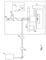
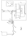
- Figures 1 and 2 show the axis or stage mode.
- the 2PP source (1) can either be performed in a layer-by-layer manner or the XYZ stage module (7) can be used to move the sample holder with respect to the 2PP source (1) as desired.
- Figures 5 and 6 show the DMD (digital mirror device) mode.
- DMD digital mirror device
- Both the DLP source (2) and the 2PP source (1) printing are performed by projecting light shaped in the geometry of each layer onto the photoresist.
- the guiding optics (3) for this mode additionally comprise a digital mirror device (10) and a ⁇ shaper (11) placed between the 2PP source (1) and the motorized nosepiece (4).
- a computer model of the structures intended to be printed in STL format is sliced, and each layer is hatched using a standard commercially available slicer. Paths for slices and hatches are translated to, for example, G-code format that can be interpreted by stages or galvo scanners. Thus, the exposure of the photoresists is determined by the sliced and hatched paths and, for example, by the G-code commands.
- DLP source (2) printing and 2PP source (1) printing in DMD configuration computer models of structures in STL format are sliced using a standard commercially available slicer, and sliced layers can be translated to images, for example, in bmp format.
- the exposure of the photoresists is determined by the sliced and hatched paths and, for example, by single bmp-files.
- DLP source (2) and 2PP source (1) can also use grayscale control to set the intensity distribution of light/laser radiation within a single layer and to compensate for optical errors.
- the grayscale control can comprise stochastic optimization techniques augmented with advanced ML/AI algorithms.
- DLP source (2) printing the DLP device enables control of the light power of every pixel.
- 2PP source (1) printing the optical 2PP system requires an attenuator.
Landscapes
- Engineering & Computer Science (AREA)
- Chemical & Material Sciences (AREA)
- Materials Engineering (AREA)
- Physics & Mathematics (AREA)
- Optics & Photonics (AREA)
- Manufacturing & Machinery (AREA)
- Mechanical Engineering (AREA)
- Health & Medical Sciences (AREA)
- Toxicology (AREA)
- Microelectronics & Electronic Packaging (AREA)
- Plasma & Fusion (AREA)
Abstract
A 3D printing device that combines one-photon printing by digital light projection (DLP) and two-photon polymerization (2PP) by means of a motorized nosepiece (4) with various microscope objectives (MO) with different numerical apertures capable of switching between said MOs, which allows for high-speed and high-resolution printing for large-area processing without limiting the 3D printing capabilities of 2PP (1).
Description
- The embodiments of the invention as illustrated and described herein relate to a 3D printing device that combines one-photon printing by digital light projection (DLP) and two-photon polymerization (2PP). This allows for high-speed and high-resolution printing for large-area processing without limiting the 3D printing capabilities of 2PP.
- High-resolution 3D printing is achieved through two-photon polymerization (2PP), a technique that utilizes a nonlinear phenomenon induced by tightly focusing ultrashort pulsed laser radiation in photosensitive material.
- While lasers with NIR (near infrared) wavelengths are commonly used for 2PP, lasers emitting ultrashort pulses at green wavelengths are also suitable. The laser radiation initiates the cross-linking of the polymer chains in a specific volume that is much smaller than the dimension of the laser focus. By guiding the laser beam through the material, 2PP allows for the printing of 2D, 2.5D, and even 3D structures using sliced computer models in most cases. This method enables the fabrication of structures with ultra-high-resolution features down to sub-100 nm without the need for a mask, vacuum, cleanroom facilities, or harsh chemicals.
- However, the slow printing speed of 2PP hinders is widespread use due to its resolution and writing scheme. Typically, standard home-built optical setups for 2PP and commercially available 2PP systems are available in two different configurations. The first configuration allows for the printing of 3D structures by translating the photosensitive material with respect to the laser beam using a highly accurate 3D axis system. Sliced models can also be used in this first configuration. In the second configuration, computer models are sliced into various layers, and each layer is processed by scanning the laser beam into its specific geometry using a galvo scanning system. Although the galvo scanner configuration enables higher printing speeds than the axis configuration, printing an area of several mm2 can take several hours, depending on the size and complexity of the 3D structure.
- Despite this, diffractive optical elements (DOEs) or spatial light modulators (SLMs) have been successfully demonstrated to enhance the processing speed of 2PP in one of the configurations.
- Another recently published option to enhance the fabrication speed of 2PP is the use of a digital mirror device (DMD), which enables spatiotemporal shaping of the laser radiation to print the entire layer geometry in a single exposure dose.
- However, every reported optimization to increase the 2PP printing speed is combined with certain limitations. For example, using a DOE or SLM (selective laser melting) enables only the processing of periodic structures, and DMD (digital metal deposition) negatively affects the resolution.
- The present invention relates to a 3D printing device that combines one-photon printing by digital light projection (DLP) and two-photon polymerization (2PP), which allows for high-speed and high-resolution printing for large-area processing without limiting the 3D printing capabilities of 2PP.
- The invention aims to advance two-photon polymerization (2PP) for large-area processes. 2PP allows for maskless 3D printing with ultra-high resolution down to the sub-100nm regime, making it an attractive option for manufacturing innovative applications in interdisciplinary fields that cannot be achieved by any other lithographic manufacturing technique.
- Unlike other proposed solutions to enhance 2PP printing speed, the invention does not focus primarily on accelerating the 2PP process, but uses it specifically where needed. Therefore, the invention combines 2PP with a lower resolution but more efficient printing approach, with DLP. DLP is a printing technique that uses thousands of electronically switchable micro-mirrors (DMD, digital micromirror device) to enable high-efficient light shaping. By combining the advantages of 2PP and DLP, the invention enables high-speed and high-resolution printing.
- Some applications that could benefit from this invention include Lab-on-Chip, Plant-on-Chip and Organ-on-Chip applications, as well as innovative real-world applications such as waveguides, microfluidic structures, tissue engineering scaffolds with superior mechanical properties, surfaces with bioinspired properties, free-form micro-optics, photonic integrated circuits, and 3D photonic metamaterials, among others. However, the present invention is not limited to a specific field.
- The invention comprises a DLP source, a 2PP source, the necessary optics to guide the light emitted by the DLP and/or 2PP towards the sample, an imaging system and illumination system therefor, a motorized nosepiece with various microscope objectives (MO) with different numerical apertures capable of switching between these MOs, an XYZ-stage system, and a resin tank.
- The present invention enables the use of 2PP in almost any configuration, allowing for the translation of samples with respect to printing arbitrary structures. However, the most convenient approach for the invention is 3D printing in a layer-by-layer manner using both DLP and 2PP. The sample is placed on a holder immersed in a tank filled with suitable resins for 3D printing approaches, using a high-precision Z-stage that also shifts the sample inside the photoresist tank after each layer has been printed.
- Generally, DLP printing is used to fabricate bulky structures (e.g., >100µm) or less complex structures that do not require ultra-high resolution, and 2PP is used to manufacture ultra-fine structures. 2PP processing can be done in axis, galvo or DMD mode. Axis and galvo mode allow a full control of the 2PP resolution, meaning that they do not limit the 2PP resolution.
- For both 2PP and DLP processing, various MOs with different numerical apertures can be selected, but for DLP, it is also possible to print without the use of an MO. In this context, DLP and 2PP can be used alternately, but both techniques can also be used simultaneously when printing is conducted with the same MO.
- Switching between these MOs is possible by using the motorized nosepiece. Before switching to another MO, the Z-stage moves the sample placed on the holder vertically to a lower position to prevent the MO from being damaged when rotating using the motorized nosepiece. An XY-translation stage with high precision and long traveling distance can be used to enable stitching if necessary for large-area structures.
- To complement the description being made and in order to aid towards a better understanding of the characteristics of the invention, in accordance with a preferred example of practical embodiment thereof, a set of drawings is attached as an integral part of said description wherein, with illustrative and non-limiting character, the following has been represented:
-
Figures 1 and2 .- Show a schematical illustration of the use of 2PP and DLP in stage mode alternately. -
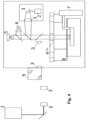
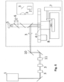
Figures 3 and4 .- Show a schematical illustration of the use of 2PP and DLP in galvo mode alternately. Infigure 3 the sample is illuminated from the bottom. -
Figures 5 and6 .- Show a schematical illustration of the use of 2PP and DLP in DMD mode alternately. - It is described below, with the help of
figures 1 to 6 , and exemplary embodiment of the 3D printing device combining digital light projection and two photon polymerization, object of the present invention, which can be used in several modes. - The printing device comprises a DLP (digital light projection) source (2), a 2PP (two-photon polymerization) source (1), both associated to guiding optics (3) to guide the light emitted by the DLP source (2) and/or 2PP source (1) towards a sample.
- The device also comprises an imaging system (5), preferably a charge-coupled device (CCD) camera, directed towards the sample, and an LED light (6), that provides light to the sample.
- Moreover, the device comprises a motorized nosepiece (4), placed between the guiding optics (3) and the sample, with various microscope objectives (MO) with different numerical apertures capable of switching between these MOs.
- Finally, the device comprises an XYZ-stage module (7) and a resin tank (8), where the sample is intended to be placed on a sample holder in the resin tank (8). Everything except the 2PP source (1) is housed within a UV-protection housing, as can be seen in
figures 1-6 . - The CCD camera (5) is used to observe the printing process. The sample is illuminated from the top using the LED light (5). However, it is also possible to illuminate the sample from the bottom if the resin is optically clear and the tank (8) and the sample holder are manufactured using transparent materials,as can be seen in
fig. 3 . - The guiding optics (3) comprise a shutter, a beam expander and a varying number of lens depending on the mode, placed between the 2PP source (1) and the sample. Additionally, the guiding optics (3) comprise a digital mirror and a lens, placed between the DLP source (2) and the sample.
-
Figures 1 and2 show the axis or stage mode. In this mode, while the DLP source (2) printing is performed in a layer-by-layer manner, the 2PP source (1) can either be performed in a layer-by-layer manner or the XYZ stage module (7) can be used to move the sample holder with respect to the 2PP source (1) as desired. -
Figures 3 and4 show the galvo mode. In this mode, all 3D printing is conducted in a layer-by-layer manner. While the DLP source (2) printing is performed by shaping the light in the geometry of each layer, the 2PP source (1) printing is performed by deflecting the laser beam in the geometry of the printed layer using galvometric mirrors (9). -
Figures 5 and6 show the DMD (digital mirror device) mode. In this mode, all 3D printing is conducted in a layer-by-layer manner. Both the DLP source (2) and the 2PP source (1) printing are performed by projecting light shaped in the geometry of each layer onto the photoresist. The guiding optics (3) for this mode additionally comprise a digital mirror device (10) and a π shaper (11) placed between the 2PP source (1) and the motorized nosepiece (4). - All three modes allow for simultaneous application of both printing methods when all printing is conducted with the same microscope objectives.
- For the 2PP source (1) printing, a computer model of the structures intended to be printed in STL format is sliced, and each layer is hatched using a standard commercially available slicer. Paths for slices and hatches are translated to, for example, G-code format that can be interpreted by stages or galvo scanners. Thus, the exposure of the photoresists is determined by the sliced and hatched paths and, for example, by the G-code commands.
- For DLP source (2) printing and 2PP source (1) printing in DMD configuration, computer models of structures in STL format are sliced using a standard commercially available slicer, and sliced layers can be translated to images, for example, in bmp format. Thus, the exposure of the photoresists is determined by the sliced and hatched paths and, for example, by single bmp-files.
- DLP source (2) and 2PP source (1) can also use grayscale control to set the intensity distribution of light/laser radiation within a single layer and to compensate for optical errors. The grayscale control can comprise stochastic optimization techniques augmented with advanced ML/AI algorithms. In the case of DLP source (2) printing, the DLP device enables control of the light power of every pixel. In the case of 2PP source (1) printing, the optical 2PP system requires an attenuator.
Claims (7)
- A 3D printing device combining digital light projection (DLP) and two photon polymerization (2PP), being the device characterized in that it comprises:- a 2PP source (1),- a DLP source (2),- a resin tank (8),- a sample holder contained within the resin tank (8), intended to hold a sample,- an XYZ-stage module (7) associated to the sample holder (9) in order to move it,- a motorized nosepiece (4) with various microscope objectives with different numerical apertures capable of switching between them, placed between the 2PP source (1) and DLP source (2) and the sample holder (9),- guiding optics (3) placed between the 2PP source (1) and the DLP source (2) and the motorized nosepiece (4), and- an imaging module (5) and illumination module (6) associated to the sample holder.
- The device according to claim 1, where the imaging module (5) is a charge-coupled device (CCD) camera.
- The device of claim 1, wherein the illumination module (6) comprises an LED light.
- The device of claim 1, wherein it additionally comprises a UV-protection housing to enclose the DLP source (2), the resin tank (8), the sample holder, the XYZ-stage module (7), the motorized nosepiece (4), the guiding optics (3), the imaging module (5) and the illumination module (6).
- The device of claim 1, wherein the guiding optics (3) comprise a shutter, a beam expander and one or more lenses placed between the 2PP source (1) and the sample holder, and a digital mirror and a lens, placed between the DLP source (2) and the sample holder.
- The device of claim 1, where the guiding optics (3) additionally comprise galvometric mirrors (9) placed between the 2PP source (1) and the motorized nosepiece (4).
- The device according to claim 1, where the guiding optics (3) additionally comprise a digital mirror device (10) and a π shaper (11) placed between the 2PP source (1) and the motorized nosepiece (4).
Applications Claiming Priority (1)
| Application Number | Priority Date | Filing Date | Title |
|---|---|---|---|
| GR20230100729A GR20230100729A (en) | 2023-09-12 | 2023-09-12 | 3d printing device combining digital light projection and two-photon polymerization |
Publications (1)
| Publication Number | Publication Date |
|---|---|
| EP4523886A1 true EP4523886A1 (en) | 2025-03-19 |
Family
ID=88923817
Family Applications (1)
| Application Number | Title | Priority Date | Filing Date |
|---|---|---|---|
| EP23386113.7A Withdrawn EP4523886A1 (en) | 2023-09-12 | 2023-11-09 | 3d printing device combining digital light projection and two-photon polymerization |
Country Status (2)
| Country | Link |
|---|---|
| EP (1) | EP4523886A1 (en) |
| GR (1) | GR20230100729A (en) |
Citations (3)
| Publication number | Priority date | Publication date | Assignee | Title |
|---|---|---|---|---|
| US20120098164A1 (en) * | 2007-07-20 | 2012-04-26 | Shyi-Herng Kan | Two-photon stereolithography using photocurable compositions |
| US20190084241A1 (en) * | 2017-09-21 | 2019-03-21 | Northwestern University | System and methods for the fabrication of three-dimensional objects via multiscale multiphoton photolithograhy |
| US20220088872A1 (en) * | 2019-01-14 | 2022-03-24 | Arizona Board Of Regents On Behalf Of The University Of Arizona | High resolution, high throughput additive manufacturing |
-
2023
- 2023-09-12 GR GR20230100729A patent/GR20230100729A/en unknown
- 2023-11-09 EP EP23386113.7A patent/EP4523886A1/en not_active Withdrawn
Patent Citations (3)
| Publication number | Priority date | Publication date | Assignee | Title |
|---|---|---|---|---|
| US20120098164A1 (en) * | 2007-07-20 | 2012-04-26 | Shyi-Herng Kan | Two-photon stereolithography using photocurable compositions |
| US20190084241A1 (en) * | 2017-09-21 | 2019-03-21 | Northwestern University | System and methods for the fabrication of three-dimensional objects via multiscale multiphoton photolithograhy |
| US20220088872A1 (en) * | 2019-01-14 | 2022-03-24 | Arizona Board Of Regents On Behalf Of The University Of Arizona | High resolution, high throughput additive manufacturing |
Also Published As
| Publication number | Publication date |
|---|---|
| GR20230100729A (en) | 2025-04-09 |
Similar Documents
| Publication | Publication Date | Title |
|---|---|---|
| US12208570B2 (en) | 3D printing of an intraocular lens having smooth, curved surfaces | |
| US7088432B2 (en) | Dynamic mask projection stereo micro lithography | |
| AU2007240215B2 (en) | Optical modeling apparatus | |
| EP2226683A1 (en) | Illumination system for use in a stereolithography apparatus | |
| US20190084241A1 (en) | System and methods for the fabrication of three-dimensional objects via multiscale multiphoton photolithograhy | |
| WO2024062696A1 (en) | 3d molding device | |
| CN111923411A (en) | Dynamic imaging 3D printing system and printing method thereof | |
| KR101659391B1 (en) | Exposure head and exposure apparatus | |
| EP2568326A1 (en) | Imaging device and imaging method for an imaging device | |
| EP4523886A1 (en) | 3d printing device combining digital light projection and two-photon polymerization | |
| KR20160038788A (en) | Drawing method | |
| KR20190089964A (en) | Optical molding machine with improved optical group | |
| CN114147957B (en) | 3D printing system based on projection exposure technology | |
| CN101258447B (en) | Exposure apparatus | |
| KR20200074163A (en) | Exposure equipment and manufacturing method of articles | |
| EP4523832A1 (en) | Line-illumination temporal focusing 3d nano-fabrication apparatus and method | |
| US12397506B2 (en) | Diagnostics and resolution optimization for scanning projection stereolithography | |
| CN112026174B (en) | Device and method for improving 3D printing precision by using DMD dynamic exposure | |
| JP7183763B2 (en) | Three-dimensional object modeling apparatus and modeling method | |
| CA3052115C (en) | 3d printing of an intraocular lens having smooth, curved surfaces | |
| KR20190027476A (en) | The pattern formation method to use multi-beam scanner | |
| WO2025227151A1 (en) | Methods and systems for forming an object by volumetric printing | |
| CN118426163A (en) | Laser transfer device | |
| Kesavan | 3D Printing of Bio Parts Using UV-SLA | |
| JPH0933819A (en) | Optical unit and vertically downward illuminator |
Legal Events
| Date | Code | Title | Description |
|---|---|---|---|
| PUAI | Public reference made under article 153(3) epc to a published international application that has entered the european phase |
Free format text: ORIGINAL CODE: 0009012 |
|
| STAA | Information on the status of an ep patent application or granted ep patent |
Free format text: STATUS: THE APPLICATION HAS BEEN PUBLISHED |
|
| AK | Designated contracting states |
Kind code of ref document: A1 Designated state(s): AL AT BE BG CH CY CZ DE DK EE ES FI FR GB GR HR HU IE IS IT LI LT LU LV MC ME MK MT NL NO PL PT RO RS SE SI SK SM TR |
|
| STAA | Information on the status of an ep patent application or granted ep patent |
Free format text: STATUS: THE APPLICATION IS DEEMED TO BE WITHDRAWN |
|
| 18D | Application deemed to be withdrawn |
Effective date: 20250920 |