EP4523852A1 - Rohrverlegungsvorrichtung mit kontrollmitteln, entsprechende anordnung und verfahren - Google Patents
Rohrverlegungsvorrichtung mit kontrollmitteln, entsprechende anordnung und verfahren Download PDFInfo
- Publication number
- EP4523852A1 EP4523852A1 EP24200163.4A EP24200163A EP4523852A1 EP 4523852 A1 EP4523852 A1 EP 4523852A1 EP 24200163 A EP24200163 A EP 24200163A EP 4523852 A1 EP4523852 A1 EP 4523852A1
- Authority
- EP
- European Patent Office
- Prior art keywords
- pipe
- force
- spigot
- fitting
- stroke
- Prior art date
- Legal status (The legal status is an assumption and is not a legal conclusion. Google has not performed a legal analysis and makes no representation as to the accuracy of the status listed.)
- Pending
Links
Images




Classifications
-
- B—PERFORMING OPERATIONS; TRANSPORTING
- B25—HAND TOOLS; PORTABLE POWER-DRIVEN TOOLS; MANIPULATORS
- B25B—TOOLS OR BENCH DEVICES NOT OTHERWISE PROVIDED FOR, FOR FASTENING, CONNECTING, DISENGAGING, OR HOLDING
- B25B27/00—Hand tools, specially adapted for fitting together or separating parts or objects whether or not involving some deformation, not otherwise provided for
- B25B27/02—Hand tools, specially adapted for fitting together or separating parts or objects whether or not involving some deformation, not otherwise provided for for connecting objects by press fit or detaching same
- B25B27/10—Hand tools, specially adapted for fitting together or separating parts or objects whether or not involving some deformation, not otherwise provided for for connecting objects by press fit or detaching same inserting fittings into hoses
Definitions
- the present invention relates to a pipe laying device, the pipe laying device being adapted to fit a plain end of a first pipe, which is a pipe to be laid, into a socket end of a second pipe, which is a pipe already laid, the socket end being provided with a sealing gasket adapted to seal a gap between the plain end and the socket end, the pipe laying device comprising means for moving the first pipe relative to the second pipe in order to fit the plain end into the socket end on a fitting stroke.
- the device is used to check the fit of a pipe to be laid (T) into a pipe already laid (To).
- the fit is checked by determining the fit length of the spigot end into the spigot end, for example using a reference stop.
- the integrity of the seal is checked after fitting using a vacuum device.
- EP3623680A1 discloses a connecting device for tubular lines for a pneumatic system or for a fuel delivery system.
- the connecting device comprises a connecting body with a receiving opening for the tubular line to be plugged in.
- a support sleeve is arranged coaxially with respect to the connecting body and inside the latter, such that the end of the tubular line can be pushed onto the cylindrical outer surface of the support sleeve.
- a retaining element is mounted inside the connecting body for fixing the plugged-in pipe end.
- a circumferential seal is arranged between the connecting body and the end of the tubular line.
- the peripheral seal produces a first haptic signal in the form of a sudden increase in insertion resistance when the end of the pipe meets the peripheral seal.
- the support sleeve comprises a sensing element which generates a second haptic signal in the form of a sharp increase in insertion resistance depending on the insertion depth of the pipe end in the insertion direction behind the peripheral seal inside the connection body.
- This document does not concern pipes for the transport of water and uses specific means to generate the characteristic succession of the first and second haptic signals.
- WO2020249265A2 describes a pipe fitting applicator.
- EP3120064 Or WO2015139148A1 discloses a device for locking a joint after a plain end has been inserted into a socket end. These documents do not concern self-sealing or self-locking joints.
- the aim of the invention is to provide a device and a method for laying pipeline pipes efficiently and reliably leading to a sealed, in particular sealed and locked, tubular joint, and which reliably and economically ensure the sealing, in particular the sealing and locking, of the tubular joint.
- pipe is defined as being a straight or bent tubular element provided with a plain end and a socket end.
- the invention relates to a pipe-laying device, as indicated above, characterized in that the pipe-laying device comprises force detection means adapted to detect the force of fitting the plain end into the socket end as a function of the position of the plain end relative to the socket end over the fitting stroke of the plain end into the socket end.
- FIG. 1 a pipe laying assembly according to the invention is shown, designated by the general reference 2.
- the Figure 1 is schematic and not to scale.
- the pipe laying assembly 2 is suitable for creating a tubular junction 4 shown in the Figure 5 in assembled state.
- the tubular junction 4 extends along a central axis X-X.
- the expressions “radially”, “axially”, “circumferentially” and “meridian” will be used with respect to this central axis.
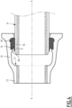
- the tubular junction 4 comprises a plain end 6, or male end, of a first pipe 8, a socket end 10, or female end, of a second pipe 12, and a gasket sealing 14.
- the tubular junction 4 consists of the plain end 6, the socket end 10 and the sealing gasket 14.
- the tubular junction 4 therefore does not have a support sleeve suitable for opposing radial deformation of the plain end 6.
- the tubular joint 4 is shown at different stages of the assembly process.
- the first pipe 8 is a pipe to be laid.
- the second pipe 12 is a pipe that is already laid. During the assembly process, the first pipe 8 is moved, while the second pipe 12 is stationary.
- the first pipe 8 is for example made of cast iron, in particular ductile iron.
- the second pipe 12 is for example made of cast iron, in particular ductile iron.
- the first pipe 8 and the second pipe 12 have for example a nominal diameter greater than or equal to 100 mm, in particular greater than or equal to 400 mm.
- the first pipe 8 and the second pipe 12 have for example a wall thickness of between 3 mm and 30 mm.
- the first pipe 8 and the second pipe 12 are for example drinking water supply pipes or sanitation pipes or irrigation pipes.
- the plain end and/or the socket end is not the plain end and/or the socket end of a tubular element of generally cylindrical shape, but the plain end and/or the socket end of another tubular element such as a tubular connector for example.
- one or other of the first and second pipes 8 and 12 may therefore be for example a tubular connector or a valve. The above characteristics of the first and second pipes 8 and 12 also apply to these other tubular elements.
- the tubular junction 4 is, for example, part of an installation in a buried trench or on supports placed on the ground, on tunnel walls or on bridges.
- the spigot end 10 comprises an inner groove 16 and a spigot bottom surface 17.
- the seal 14 is inserted into this inner groove 16.
- the seal 14 is adapted to make the gap between the plain end and the spigot end watertight.
- the sealing gasket 14 comprises, in the meridian section, an elastic ring made of flexible or resilient material, for example elastomer, which extends along the central axis X-X.
- the seal 14 forms an anchor heel 18 and a self-sealing sealing lip 20.
- self-sealing means that the seal is obtained upon insertion of the spigot end into the socket end by radial compression of the seal 14 by the spigot end and the socket end and subsequently reinforced by the pressure of the liquid flowing in the first and second pipes.
- the sealing gasket 14, respectively the tubular junction 4, of the embodiment of the Figures 1 to 5 is devoid of locking inserts locking the plain end relative to the socket end.
- the tubular junction 4 defines a nesting stroke CE, which is the movement of the spigot end 6 relative to the nested end 12 between an assembly start position ( Figure 1 ) and an assembly end position ( Figure 5 ).
- the nesting stroke CE is directed in a nesting direction SE, which is coaxial with the central axis XX and directed from the plain end 6 towards the nested end 10.
- the pipe laying assembly 2 further comprises a pipe laying device 30 adapted to fit the plain end 6 of the first pipe 8 into the socket end 10 of the second pipe 12.
- the pipe laying device 30 comprises means 32 for moving the first pipe 8 relative to the second pipe 12 in order to fit the plain end into the fitting end on the fitting stroke CE.
- the displacement means 32 comprise an actuator 34 adapted to drive the plain end relative to the interlocking end.
- the actuator 34 is preferably a hydraulic cylinder 36.
- the actuator 34 is for example an electric cylinder or a rack mechanism.
- the displacement means 32 further comprise two gripping elements 38, 40 for gripping the first pipe 8 relative to the second pipe 12, such as suction cups.
- One of the gripping elements, in this case the gripping element 38, is connected to the actuator 34 in order to transmit the displacement induced by the actuator 34 to the plain end 6.
- the displacement means 32 further comprise a source of pressurized fluid 42, for example a pump, connected to the hydraulic cylinder 36 by two fluid lines 44, 46.
- a source of pressurized fluid 42 for example a pump
- One and the other of the two fluid lines 44, 46 are respectively connected to one and the other of two working chambers 48, 50 of the hydraulic cylinder 36.
- the displacement means 32 further comprise switching means 52, such as a switching valve, in order to selectively connect the source of pressurized fluid 42 to one or the other of the two working chambers 48, 50.
- switching means 52 such as a switching valve
- the pipe laying device 30 further comprises force detection means 60 adapted to detect the fitting force F of the plain end 6 in the fitting end 10 as a function of the position of the plain end relative to the fitting end over the fitting stroke CE of the plain end in the fitting end.
- the interlocking force is the resisting force opposing a displacement of the spigot in the SE interlocking direction.
- the force detection means 60 comprise in this case a pressure sensor 62 adapted to detect the pressure of the fluid in the pressure chamber 48.
- the pressure sensor 62 can for example be arranged in the fluid line 44 ( Figure 1 ) or be arranged between the fluid line 44 and the fluid inlet in a housing of the hydraulic cylinder 36.
- the force detection means 60 comprise a force sensor adapted to detect a force, such as a strain gauge.
- the force sensor is disposed on an element located in the flow of forces moving the spigot end relative to the socket end.
- the force sensor is disposed on a piston rod 64 of the hydraulic cylinder 36.
- the force detection means 60 further comprise conversion means in order to convert the pressure P detected by the pressure sensor 62 into a force.
- the pipe laying device 30 further comprises stroke detection means 66 adapted to record the distance traveled by the spigot end 6 over the fitting stroke CE.
- These stroke detection means 66 comprise in this case a position sensor 68, which is adapted to record the position of the spigot end 6 relative to the fitting end 10.
- the position sensor 68 is for example arranged on the hydraulic cylinder 36 and adapted to record the position of the piston rod of the hydraulic cylinder relative to the casing of the hydraulic cylinder.
- the position sensor 68 is a camera detecting an image of the spigot end and the fitting end.
- the position sensor 68 is a speed sensor measuring the speed of movement of the spigot end relative to the fitting end associated with means for integrating the speed captured over time.
- the pipe laying device 30 also comprises a control device 70.
- the control device 70 is for example a microcomputer or a microcontroller.
- the control device 70 comprises a processor, a RAM, a ROM and control inputs and outputs.
- the control device 70 is adapted to control the displacement means 32.
- the control device 70 is connected by a control line 72 to the source of pressurized fluid 42 and by a control line 74 to the switching means 52.
- the control device 70 is connected by a control line 76 to the pressure sensor 62, allowing the control device 70 to read the pressure detected by the pressure sensor.
- the means for converting the pressure detected by the pressure sensor 62 into a force are advantageously implemented by the control device 70, for example in the form of software. Alternatively, the conversion means may be integrated into the pressure sensor 62.
- the control device 70 is connected by a control line 78 to the position sensor 68 in order to detect the position of the spigot end 6 relative to the socket end 10.
- the control device 70 is therefore adapted to generate and manage nesting data representing the nesting stroke CE, carried out by the displacement means, and the nesting force F detected by the force detection means, on the nesting stroke CE.
- the control device 70 comprises or is connected to a memory adapted to store the nesting data representing the nesting stroke CE, carried out by the displacement means, and the nesting force F detected by the force detection means, on the nesting stroke CE for a given tubular junction 4.
- the pipe laying device 30 also comprises means for displaying nesting data 80, these data representing the nesting stroke, carried out by the displacement means, and the nesting force F detected by the force detection means, on the nesting stroke CE.
- These nesting data display means 80 comprise for example a screen 82 and a display line 84 connecting the screen 82 to the control device 70 and more particularly to the storage memory.
- the pipe laying device 30 further comprises data archiving means 90.
- These data archiving means 90 are adapted to archive and archive the nesting data representing the nesting stroke, carried out by the displacement means, and the nesting force detected by the force detection means, on this nesting stroke for a given tubular junction 4.
- the data archiving means 90 are also adapted to archive and archive management data associating the nesting data with the given tubular junction 4.
- These management data comprise for example unambiguous identification data of the tubular junction 4, such as serial numbers of the spigot end, the spigot end and/or the seal, the date and/or time of the laying, the geolocation of the laying site.
- the data archiving means 90 are advantageously adapted to archive and archive the nesting data for several tubular junctions 4, in particular the tubular junctions 4 of a given site.
- the pipe laying device 30 comprises evaluation means 100, adapted to evaluate, as a function of the fitting force detected by the force detection means on the fitting stroke CE, whether the tubular junction 4 created by the fitting of the plain end into the socket end on the fitting stroke CE is correctly established, that is to say whether the tubular junction 4 is watertight or, where appropriate, watertight and locked.
- the evaluation means 100 comprise a memory containing typical nesting data representing the nesting force over the nesting stroke CE corresponding to a correct nesting of a given tubular junction 4. These typical nesting data are represented on the Figure 7 in dashed lines, corresponding to the high and low tolerances.
- the evaluation means 100 comprise an evaluation module 104.
- the evaluation means 100 or the evaluation module 104 comprise means for comparing the nesting data of a given tubular junction 4 with the typical nesting data.
- the pipe laying device 30 also comprises means for signaling the status of the given tubular junction 4 as a function of the result of the comparison carried out by the comparison means.
- These signaling means may for example comprise the nesting data display means 80 or the screen 82.
- the evaluation means 100 are furthermore adapted to detect, as a function of the interlocking data or as a function of the interlocking force detected by the force detection means on the interlocking stroke CE of a given tubular junction 4, at least one of the various possible junction defects.
- Each junction fault detectable by the evaluation module corresponds to typical fault data.
- the evaluation means 100 comprise a memory of typical defects containing for each detectable junction defect the typical defect data. Before describing the characteristics of each junction defect, the nesting process will be described subsequently in the case of a correctly established tubular junction 4.
- the first pipe 8 and the second pipe 12 are coaxial.
- the plain end 6 is axially offset from the socket end 10 and located outside the socket end 10.
- the sealing gasket 14 is located in the inner groove 16 of the second pipe 12.
- a first nesting step which is an approach step, the nesting force which corresponds to the movement of the spigot end is low (almost zero), and this until the spigot end 6 comes into contact with the sealing gasket 14.
- This approach step is represented by A [A surrounded by a circle] on the Figure 7 and corresponds to the step of moving the spigot between the Figures 1 And 2 .
- the fitting force gradually increases as the spigot moves.
- the stroke-force curve is inclined with a positive gradient on the abscissa.
- This step of flaring and compressing the seal is represented by B [B surrounded by a circle] on the Figure 7 and corresponds to the step of moving between the Figures 2 And 3 during which the interlocking force reaches a maximum value.
- a third nesting step which is a spigot penetration step
- the nesting force gradually decreases as the spigot moves.
- the stroke-force curve is inclined with a negative gradient on the abscissa.
- the gradient is, however, less than the gradient during the second nesting step.
- This spigot penetration step is represented by C [C surrounded by a circle] on the Figure 7 and corresponds to the stage during which the plain end slides into the seal ( Figure 4 ).
- a fourth nesting step which is an end-of-stroke step
- the stroke-force curve is inclined with a negative gradient on the abscissa greater than that of the third nesting step.
- This end-of-stroke step is represented by D [D surrounded by a circle] on the Figure 7 and corresponds to the step during which action is stopped on the actuator 34 of the displacement means 32, the plain end being finally immobilized in the position of the Figure 5 .
- the tubular junction 4 is established and is watertight.
- the plain end 6 is axially distant from the bottom surface of the fitting.
- the stroke-force curves of various junction defects are shown in the Figure 7 by dotted lines a) to g).
- the stroke-force curves of the various junction defects of the Figure 7 indicate the stroke-force curve shape of each defect compared to the stroke-force curve shapes of other defects and to the stroke-force curve shape of a correctly established tubular junction.
- the stroke-force curve is initially horizontal during the approach stage (the socket force being initially low), then vertical at a point which corresponds to the contact of the plain end 6 with the front face of the socket end 10. This defect appears during a radial offset of the plain end relative to the socket end, when the two pipes to be joined are not aligned.
- the stroke-force curve is identical to that of the first fitting step and that of the beginning of the second fitting step.
- a seal ejection step occurs, resulting in a sharp decrease in the stroke-force curve during the displacement of the spigot.
- the stroke-force curve during seal ejection is inclined with a negative gradient on the abscissa. Then, on the stroke corresponding to the third fitting step, the fitting force is lower and corresponds only to the axial displacement force which pushes the ejected seal from its housing.
- defect d which corresponds to a partial pinching of the seal 14
- the stroke-force curve is identical to that of the first fitting step and follows that of the second fitting step until the partial pinching of the seal, which then results in an inclination of the curve with a negative gradient on the abscissa.
- This partial pinching defect corresponds, for example, to a seal partially removed from its seal track but without being ejected, because it was caught on a sector by the plain end or initially poorly positioned in the internal groove 16.
- the stroke-force curve is identical to that of the first, second and third stages of nesting. Then, during the fourth nesting step, the shock at the bottom of the nesting results in a strong inclination of the curve (almost vertical, with a positive gradient on the abscissa) due to the sudden increase in the nesting force at a point which corresponds to the contact of the spigot end 6 against the bottom of the nesting, the movement of the spigot end being blocked.
- This defect appears in particular when the nesting stroke CE is too long because the actuator 34 continues to maintain the nesting force.
- the stroke-force curve is identical to that of the first and second socketing stages.
- the spigot stops prematurely before reaching the point defined in the typical socketing data.
- the curve has a strong negative gradient on the abscissa.
- action on the actuator 34 of the displacement means 32 is stopped, the spigot being finally immobilized in the position of the Figure 5
- This defect appears when the gripping element 38, 40 has lost its initial position during one of the first, second or third steps (sliding for example).
- defect g which corresponds to a non-conformity in the hardness and/or dimensions of a batch of sealing gaskets
- the gasket is correctly positioned and the joint is watertight, but made with fitting forces that are either too high or too low, outside the recommended force range.
- the indication of this type of defect indicates a quality defect for the batch of gaskets concerned.
- the pipe laying device 30 Upon or after the establishment of the tubular junction 4, the pipe laying device 30 displays the nesting data.
- the operator decides, based on the nesting data, including the stroke-force curve, whether the tubular joint 4 has been correctly established. The operator can take immediate corrective action if necessary.
- the tubular junction variant of the Figure 6 differs from that previously described only in that the seal 14 comprises locking inserts 22 which allow the tubular joint to be automatically locked, preventing it from being dislodged.
- the locking inserts 22 are embedded in the seal 14.
- a fifth fitting step takes place, which is a locking step.
- the spigot end 6 is moved back relative to the spigot end 10 by a locking distance DV in order to bring the locking inserts 22 into their latching position in the spigot end.
- the stroke-force curve in the direction of the retraction, has an increasing inclination and ends with a vertical section, which corresponds to the locking state of the spigot end in the spigot end.
- the fifth step is represented schematically by E [E surrounded by a circle] on the Figure 7 , in broken lines.
- the pipe-laying device 30, the assembly and the method according to the invention make it possible to check, for each tubular junction, the correct positioning of the sealing gasket in its housing at the time of fitting carried out at the bottom of the trench or on supports placed on the ground, on tunnel walls or on bridges.
- the pipe-laying device 30, the assembly and the method according to the invention also make it possible to monitor and anticipate the risks of deviations arising either from the nesting operation, or from the characteristics of the parts supplied, such as sealing gaskets outside the tolerances, or from the surrounding conditions such as temperature or humidity for example.
- data archiving means for example a database
- data archiving means for example a database
Landscapes
- Engineering & Computer Science (AREA)
- Mechanical Engineering (AREA)
- Quick-Acting Or Multi-Walled Pipe Joints (AREA)
- Sewage (AREA)
Applications Claiming Priority (1)
| Application Number | Priority Date | Filing Date | Title |
|---|---|---|---|
| FR2309691A FR3153122A1 (fr) | 2023-09-14 | 2023-09-14 | Dispositif de pose de tuyaux avec moyens de contrôle, ensemble et procédé correspondants |
Publications (1)
| Publication Number | Publication Date |
|---|---|
| EP4523852A1 true EP4523852A1 (de) | 2025-03-19 |
Family
ID=89068876
Family Applications (1)
| Application Number | Title | Priority Date | Filing Date |
|---|---|---|---|
| EP24200163.4A Pending EP4523852A1 (de) | 2023-09-14 | 2024-09-13 | Rohrverlegungsvorrichtung mit kontrollmitteln, entsprechende anordnung und verfahren |
Country Status (2)
| Country | Link |
|---|---|
| EP (1) | EP4523852A1 (de) |
| FR (1) | FR3153122A1 (de) |
Citations (10)
| Publication number | Priority date | Publication date | Assignee | Title |
|---|---|---|---|---|
| JPH04215025A (ja) * | 1990-12-13 | 1992-08-05 | Yokohama Rubber Co Ltd:The | ホ−スのニップル挿入力測定装置 |
| US20090299514A1 (en) * | 2008-06-02 | 2009-12-03 | Swagelok Company | Fitting assembly evaluating apparatus and methods |
| FR2966554A1 (fr) * | 2010-10-26 | 2012-04-27 | Saint Gobain Pont A Mousson | Insert de verrouillage, garniture d'etancheite et assemblage correspondants |
| WO2015139148A1 (de) | 2014-03-20 | 2015-09-24 | Theodor Wüst | Steckmuffe |
| CN107314177A (zh) * | 2017-08-11 | 2017-11-03 | 昆山普拉斯克机械制造有限公司 | 承插口、试压方法及管网 |
| EP3623680A1 (de) | 2018-09-17 | 2020-03-18 | Voss Automotive GmbH | Anschlussvorrichtung für rohrleitungen |
| WO2020141266A1 (fr) | 2019-01-03 | 2020-07-09 | Acimex | Appareil de pose de tuyaux de canalisation |
| WO2020249265A2 (de) | 2019-06-14 | 2020-12-17 | Wuest Theodor | Rohrverbindungs-applikator und verfahren zur herstellung einer verbindung |
| CN114184484A (zh) * | 2021-11-26 | 2022-03-15 | 佛山电力设计院有限公司 | 一种顶管管节偏转状态下接头密封及受力传递监测装置及方法 |
| CN116330221A (zh) * | 2023-03-15 | 2023-06-27 | 徐州市公路工程总公司 | 一种用于承插管道连接的安装装置 |
-
2023
- 2023-09-14 FR FR2309691A patent/FR3153122A1/fr active Pending
-
2024
- 2024-09-13 EP EP24200163.4A patent/EP4523852A1/de active Pending
Patent Citations (12)
| Publication number | Priority date | Publication date | Assignee | Title |
|---|---|---|---|---|
| JPH04215025A (ja) * | 1990-12-13 | 1992-08-05 | Yokohama Rubber Co Ltd:The | ホ−スのニップル挿入力測定装置 |
| US20090299514A1 (en) * | 2008-06-02 | 2009-12-03 | Swagelok Company | Fitting assembly evaluating apparatus and methods |
| FR2966554A1 (fr) * | 2010-10-26 | 2012-04-27 | Saint Gobain Pont A Mousson | Insert de verrouillage, garniture d'etancheite et assemblage correspondants |
| WO2015139148A1 (de) | 2014-03-20 | 2015-09-24 | Theodor Wüst | Steckmuffe |
| EP3120064A1 (de) | 2014-03-20 | 2017-01-25 | Theodor Wüst | Steckmuffe |
| CN107314177A (zh) * | 2017-08-11 | 2017-11-03 | 昆山普拉斯克机械制造有限公司 | 承插口、试压方法及管网 |
| EP3623680A1 (de) | 2018-09-17 | 2020-03-18 | Voss Automotive GmbH | Anschlussvorrichtung für rohrleitungen |
| WO2020141266A1 (fr) | 2019-01-03 | 2020-07-09 | Acimex | Appareil de pose de tuyaux de canalisation |
| WO2020249265A2 (de) | 2019-06-14 | 2020-12-17 | Wuest Theodor | Rohrverbindungs-applikator und verfahren zur herstellung einer verbindung |
| AU2020292544A1 (en) * | 2019-06-14 | 2021-12-16 | Swiss Tech Innovation AG | Pipe coupling applicator and method for producing a coupling |
| CN114184484A (zh) * | 2021-11-26 | 2022-03-15 | 佛山电力设计院有限公司 | 一种顶管管节偏转状态下接头密封及受力传递监测装置及方法 |
| CN116330221A (zh) * | 2023-03-15 | 2023-06-27 | 徐州市公路工程总公司 | 一种用于承插管道连接的安装装置 |
Also Published As
| Publication number | Publication date |
|---|---|
| FR3153122A1 (fr) | 2025-03-21 |
Similar Documents
| Publication | Publication Date | Title |
|---|---|---|
| EP3080504B1 (de) | Verbindungsendstück eines flexiblen rohrs, zugehörige vorrichtung und verfahren | |
| EP3014157B1 (de) | Schlauch und verfahren dafür | |
| EP3601985B1 (de) | Vorrichtung zur dichtungsprüfung, rohrverbindung und entsprechende verwendung | |
| FR2978231A1 (fr) | Dispositif de raccord anti-flambage pour tuyauteries | |
| CA2890675A1 (fr) | Procede de controle d'un etat de vissage d'un joint filete tubulaire | |
| WO2009092908A2 (fr) | Dispositif de mesure du mouvement d'une conduite sous-marine déformable | |
| EP3529577B1 (de) | Verfahren zur überwachung der erhebung einer unterwasserleitungsboje | |
| EP4523852A1 (de) | Rohrverlegungsvorrichtung mit kontrollmitteln, entsprechende anordnung und verfahren | |
| WO2008148944A1 (fr) | Dispositif d'etancheite servant a obturer un puits et une canalisation et un procede de montage | |
| WO2017009460A1 (fr) | Dispositif d'isolation pour puits avec un disque de rupture | |
| EP3732386A1 (de) | Anschlussspitze für eine flexible leitung sowie zugehöriges herstellungsverfahren und überwachungsverfahren | |
| CN110411391B (zh) | 管道轴向位移检测装置和方法 | |
| WO1992015768A1 (fr) | Methode de verification du bon fonctionnement d'une vanne de securite d'un puits petrolier | |
| WO2016166477A1 (fr) | Procédé de détermination de la pression interstitielle dans le sediment marin et dispositif correspondant | |
| FR3096752A1 (fr) | Racleur instrumenté pour l’inspection de canalisations de pipelines. | |
| EP4264172B1 (de) | Vorrichtung und verfahren zur messung des mechanischen spiels in einer hydraulikleitung | |
| FR2862367A1 (fr) | Raccord a sertir a corps conducteur | |
| FR3120929A1 (fr) | procédé de rénovation de canalisation par l’intérieur | |
| WO2003071179A1 (fr) | Embout instrumente de conduite flexible adapte a la detection du deplacement d'une couche de conduite, et conduite associee | |
| FR2844860A1 (fr) | Connecteur rapide a securite accrue | |
| EP3985295A1 (de) | Fluidverbindung vom typ patrone | |
| FR3138520A1 (fr) | Système et procédé pour détecter une panne dans un trajet de fluide d’un système de fluide | |
| FR3154477A1 (fr) | Système de réparation de fuite d’un conduit de distribution d’eau | |
| FR2825799A1 (fr) | Dispositifs et procedes de detection et de localisation de fuite dans une canalisation | |
| FR2583849A1 (fr) | Procede et dispositif pour la detection des fuites dans les canalisations |
Legal Events
| Date | Code | Title | Description |
|---|---|---|---|
| PUAI | Public reference made under article 153(3) epc to a published international application that has entered the european phase |
Free format text: ORIGINAL CODE: 0009012 |
|
| STAA | Information on the status of an ep patent application or granted ep patent |
Free format text: STATUS: THE APPLICATION HAS BEEN PUBLISHED |
|
| AK | Designated contracting states |
Kind code of ref document: A1 Designated state(s): AL AT BE BG CH CY CZ DE DK EE ES FI FR GB GR HR HU IE IS IT LI LT LU LV MC ME MK MT NL NO PL PT RO RS SE SI SK SM TR |
|
| STAA | Information on the status of an ep patent application or granted ep patent |
Free format text: STATUS: REQUEST FOR EXAMINATION WAS MADE |
|
| 17P | Request for examination filed |
Effective date: 20250819 |