EP4523820A1 - Turret lathe, and tool preparation method - Google Patents
Turret lathe, and tool preparation method Download PDFInfo
- Publication number
- EP4523820A1 EP4523820A1 EP22964410.9A EP22964410A EP4523820A1 EP 4523820 A1 EP4523820 A1 EP 4523820A1 EP 22964410 A EP22964410 A EP 22964410A EP 4523820 A1 EP4523820 A1 EP 4523820A1
- Authority
- EP
- European Patent Office
- Prior art keywords
- designated
- tool
- mounting surface
- operation pattern
- turret
- Prior art date
- Legal status (The legal status is an assumption and is not a legal conclusion. Google has not performed a legal analysis and makes no representation as to the accuracy of the status listed.)
- Pending
Links
Images



















Classifications
-
- B—PERFORMING OPERATIONS; TRANSPORTING
- B23—MACHINE TOOLS; METAL-WORKING NOT OTHERWISE PROVIDED FOR
- B23B—TURNING; BORING
- B23B7/00—Automatic or semi-automatic turning-machines with a single working-spindle, e.g. controlled by cams; Equipment therefor; Features common to automatic and semi-automatic turning-machines with one or more working-spindles
- B23B7/02—Automatic or semi-automatic machines for turning of stock
- B23B7/04—Turret machines
-
- B—PERFORMING OPERATIONS; TRANSPORTING
- B23—MACHINE TOOLS; METAL-WORKING NOT OTHERWISE PROVIDED FOR
- B23B—TURNING; BORING
- B23B25/00—Accessories or auxiliary equipment for turning-machines
- B23B25/06—Measuring, gauging, or adjusting equipment on turning-machines for setting-on, feeding, controlling, or monitoring the cutting tools or work
-
- B—PERFORMING OPERATIONS; TRANSPORTING
- B23—MACHINE TOOLS; METAL-WORKING NOT OTHERWISE PROVIDED FOR
- B23B—TURNING; BORING
- B23B29/00—Holders for non-rotary cutting tools; Boring bars or boring heads; Accessories for tool holders
- B23B29/24—Tool holders for a plurality of cutting tools, e.g. turrets
-
- B—PERFORMING OPERATIONS; TRANSPORTING
- B23—MACHINE TOOLS; METAL-WORKING NOT OTHERWISE PROVIDED FOR
- B23B—TURNING; BORING
- B23B29/00—Holders for non-rotary cutting tools; Boring bars or boring heads; Accessories for tool holders
- B23B29/24—Tool holders for a plurality of cutting tools, e.g. turrets
- B23B29/242—Turrets, without description of the angular positioning device
-
- B—PERFORMING OPERATIONS; TRANSPORTING
- B23—MACHINE TOOLS; METAL-WORKING NOT OTHERWISE PROVIDED FOR
- B23B—TURNING; BORING
- B23B29/00—Holders for non-rotary cutting tools; Boring bars or boring heads; Accessories for tool holders
- B23B29/24—Tool holders for a plurality of cutting tools, e.g. turrets
- B23B29/32—Turrets adjustable by power drive, i.e. turret heads
- B23B29/323—Turrets with power operated angular positioning devices
-
- B—PERFORMING OPERATIONS; TRANSPORTING
- B23—MACHINE TOOLS; METAL-WORKING NOT OTHERWISE PROVIDED FOR
- B23Q—DETAILS, COMPONENTS, OR ACCESSORIES FOR MACHINE TOOLS, e.g. ARRANGEMENTS FOR COPYING OR CONTROLLING; MACHINE TOOLS IN GENERAL CHARACTERISED BY THE CONSTRUCTION OF PARTICULAR DETAILS OR COMPONENTS; COMBINATIONS OR ASSOCIATIONS OF METAL-WORKING MACHINES, NOT DIRECTED TO A PARTICULAR RESULT
- B23Q17/00—Arrangements for observing, indicating or measuring on machine tools
- B23Q17/22—Arrangements for observing, indicating or measuring on machine tools for indicating or measuring existing or desired position of tool or work
-
- B—PERFORMING OPERATIONS; TRANSPORTING
- B23—MACHINE TOOLS; METAL-WORKING NOT OTHERWISE PROVIDED FOR
- B23Q—DETAILS, COMPONENTS, OR ACCESSORIES FOR MACHINE TOOLS, e.g. ARRANGEMENTS FOR COPYING OR CONTROLLING; MACHINE TOOLS IN GENERAL CHARACTERISED BY THE CONSTRUCTION OF PARTICULAR DETAILS OR COMPONENTS; COMBINATIONS OR ASSOCIATIONS OF METAL-WORKING MACHINES, NOT DIRECTED TO A PARTICULAR RESULT
- B23Q17/00—Arrangements for observing, indicating or measuring on machine tools
- B23Q17/22—Arrangements for observing, indicating or measuring on machine tools for indicating or measuring existing or desired position of tool or work
- B23Q17/2233—Arrangements for observing, indicating or measuring on machine tools for indicating or measuring existing or desired position of tool or work for adjusting the tool relative to the workpiece
-
- G—PHYSICS
- G05—CONTROLLING; REGULATING
- G05B—CONTROL OR REGULATING SYSTEMS IN GENERAL; FUNCTIONAL ELEMENTS OF SUCH SYSTEMS; MONITORING OR TESTING ARRANGEMENTS FOR SUCH SYSTEMS OR ELEMENTS
- G05B19/00—Program-control systems
- G05B19/02—Program-control systems electric
- G05B19/18—Numerical control [NC], i.e. automatically operating machines, in particular machine tools, e.g. in a manufacturing environment, so as to execute positioning, movement or co-ordinated operations by means of program data in numerical form
- G05B19/401—Numerical control [NC], i.e. automatically operating machines, in particular machine tools, e.g. in a manufacturing environment, so as to execute positioning, movement or co-ordinated operations by means of program data in numerical form characterised by control arrangements for measuring, e.g. calibration and initialisation, measuring workpiece for machining purposes
- G05B19/4015—Numerical control [NC], i.e. automatically operating machines, in particular machine tools, e.g. in a manufacturing environment, so as to execute positioning, movement or co-ordinated operations by means of program data in numerical form characterised by control arrangements for measuring, e.g. calibration and initialisation, measuring workpiece for machining purposes going to a reference at the beginning of machine cycle, e.g. for calibration
-
- B—PERFORMING OPERATIONS; TRANSPORTING
- B23—MACHINE TOOLS; METAL-WORKING NOT OTHERWISE PROVIDED FOR
- B23Q—DETAILS, COMPONENTS, OR ACCESSORIES FOR MACHINE TOOLS, e.g. ARRANGEMENTS FOR COPYING OR CONTROLLING; MACHINE TOOLS IN GENERAL CHARACTERISED BY THE CONSTRUCTION OF PARTICULAR DETAILS OR COMPONENTS; COMBINATIONS OR ASSOCIATIONS OF METAL-WORKING MACHINES, NOT DIRECTED TO A PARTICULAR RESULT
- B23Q2220/00—Machine tool components
- B23Q2220/002—Tool turrets
-
- G—PHYSICS
- G05—CONTROLLING; REGULATING
- G05B—CONTROL OR REGULATING SYSTEMS IN GENERAL; FUNCTIONAL ELEMENTS OF SUCH SYSTEMS; MONITORING OR TESTING ARRANGEMENTS FOR SUCH SYSTEMS OR ELEMENTS
- G05B2219/00—Program-control systems
- G05B2219/30—Nc systems
- G05B2219/36—Nc in input of data, input key till input tape
- G05B2219/36204—Lathe, turning
-
- G—PHYSICS
- G05—CONTROLLING; REGULATING
- G05B—CONTROL OR REGULATING SYSTEMS IN GENERAL; FUNCTIONAL ELEMENTS OF SUCH SYSTEMS; MONITORING OR TESTING ARRANGEMENTS FOR SUCH SYSTEMS OR ELEMENTS
- G05B2219/00—Program-control systems
- G05B2219/30—Nc systems
- G05B2219/45—Nc applications
- G05B2219/45141—Turret lathe
-
- G—PHYSICS
- G05—CONTROLLING; REGULATING
- G05B—CONTROL OR REGULATING SYSTEMS IN GENERAL; FUNCTIONAL ELEMENTS OF SUCH SYSTEMS; MONITORING OR TESTING ARRANGEMENTS FOR SUCH SYSTEMS OR ELEMENTS
- G05B2219/00—Program-control systems
- G05B2219/30—Nc systems
- G05B2219/50—Machine tool, machine tool null till machine tool work handling
- G05B2219/50016—Turret with multiple workpiece holders, spindles, multiple fixed tools around it
-
- G—PHYSICS
- G05—CONTROLLING; REGULATING
- G05B—CONTROL OR REGULATING SYSTEMS IN GENERAL; FUNCTIONAL ELEMENTS OF SUCH SYSTEMS; MONITORING OR TESTING ARRANGEMENTS FOR SUCH SYSTEMS OR ELEMENTS
- G05B2219/00—Program-control systems
- G05B2219/30—Nc systems
- G05B2219/50—Machine tool, machine tool null till machine tool work handling
- G05B2219/50141—Setup tool, preset
-
- G—PHYSICS
- G05—CONTROLLING; REGULATING
- G05B—CONTROL OR REGULATING SYSTEMS IN GENERAL; FUNCTIONAL ELEMENTS OF SUCH SYSTEMS; MONITORING OR TESTING ARRANGEMENTS FOR SUCH SYSTEMS OR ELEMENTS
- G05B2219/00—Program-control systems
- G05B2219/30—Nc systems
- G05B2219/50—Machine tool, machine tool null till machine tool work handling
- G05B2219/50277—Detection tool presence in tool holder, spindle before starting motor
Definitions
- the present invention relates to a turret lathe and a tool preparation method.
- PTL1 JP 2015-9345 A .
- the turret lathe includes: a turret that has a plurality of mounting surfaces; a rotation drive unit that rotates the turret about a first axis; a moving unit that moves the turret; a measurement unit that measures a position of a tool nose; and a controller configured to execute a first determination processing of determining whether or not a designated tool is attached to a designated mounting surface that is one of the plurality of mounting surfaces, to select a specific operation pattern from a plurality of operation patterns based on a result of the first determination processing, and to send a control command to the rotation drive unit and the moving unit so that the selected operation pattern is executed.
- the plurality of operation patterns includes at least a first operation pattern to be executed when the result of the first determination processing indicates that the designated tool is not attached to the designated mounting surface, and a second operation pattern to be executed when the result of the first determination processing indicates that the designated tool is attached to the designated mounting surface.
- the first operation pattern includes: rotating the turret about the first axis for the designated mounting surface to be brought to an indexed mounting position before the designated tool is attached to the designated mounting surface; rotating the turret about the first axis for the designated mounting surface to be brought to an indexed position for tool nose position measurement after the designated tool has been attached to the designated mounting surface; and measuring the nose position of the designated tool using the measurement unit.
- the second operation pattern includes rotating the turret about the first axis for the designated mounting surface with the designated tool mounted thereon to be directly brought to the indexed position for tool nose position measurement, and measuring the nose position of the designated tool using the measurement unit.
- the tool preparation method includes: executing, by a controller, a first determination processing of determining whether or not a designated tool is attached to a designated mounting surface that is one of a plurality of mounting surfaces of a turret; selecting, by the controller, a specific operation pattern from among a plurality of operation patterns based on a result of the first determination processing; and sending, by the controller, a control command to a rotation drive unit configured to rotate the turret about a first axis, and to the moving unit configured to move the turret, so that the selected specific operation pattern is executed.
- the plurality of operation patterns includes at least a first operation pattern to be executed when the result of the first determination processing indicates that the designated tool is not attached to the designated mounting surface, and a second operation pattern to be executed when the result of the first determination processing indicates that the designated tool is attached to the designated mounting surface.
- the first operation pattern includes: rotating the turret about the first axis for the designated mounting surface to be brought to an indexed mounting position before the designated tool is attached to the designated mounting surface; rotating the turret about the first axis for the designated mounting surface to be brought to an indexed position for tool nose position measurement after the designated tool has been attached to the designated mounting surface; and measuring the nose position of the designated tool using the measurement unit.
- the second operation pattern includes rotating the turret about the first axis for the designated mounting surface with the designated tool mounted thereon to be directly brought to the indexed position for tool nose position measurement, and measuring the nose position of the designated tool using the measurement unit.
- the present invention can provide a turret lathe and a tool preparation method that allow efficient execution of a procedure including measurement of a nose position.
- a tool B is usually attached to a mounting surface 6 of the turret E via a tool holding unit H (e.g., tool holder). It follows that mounting the tool on the turret herein shall include mounting the tool on the turret via the tool holding unit.
- a tool holding unit H e.g., tool holder
- a tool is herein defined as a designated tool when it is predetermined on which of the plurality of mounting surfaces of the turret E the tool is to be mounted.
- the tools are designated based on a machining program, for example.
- One of the plurality of mounting surfaces 6 of the turret E on which the designated tool is to be mounted is herein defined as a designated mounting surface. More specifically, one of the plurality of mounting surfaces 6 of the turret E on which a first designated tool is to be mounted is herein defined as a first designated mounting surface. Where "K” represents any natural number equal to or greater than 2, one of the plurality of mounting surfaces 6 of the turret E on which a "K-th" designated tool is to be mounted is herein defined as a "K-th" designated mounting surface.
- a tool that is not required in a next machining processing is herein defined as a non-designated tool 5'.
- FIG. 1 is a schematic perspective diagram illustrating the turret lathe 1A in the first embodiment.
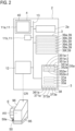
- FIG. 2 is a block diagram illustrating a hardware configuration example of a controller 2.
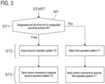
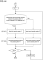
- FIG. 3 is a flowchart showing one example of the tool preparation method in the first embodiment.
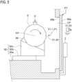
- FIG. 4 and FIG. 5 are schematic cross-sectional diagrams illustrating one part of the turret lathe 1A in the first embodiment.
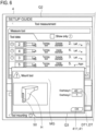
- FIG. 6 is a diagram illustrating an image Q3 shown on a display 4, prompting to mount a designated tool 50.
- FIG. 14 are schematic cross-sectional diagrams illustrating one part of the turret lathe 1A in the first embodiment.
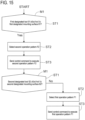
- FIG. 15 is a flowchart showing one example of the tool preparation method in the first embodiment.
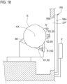
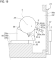
- FIG. 16 to FIG. 20 are schematic cross-sectional diagrams illustrating one part of the turret lathe 1A in the first embodiment.
- FIG. 21 is a flowchart showing one example of the tool preparation method in the first embodiment.
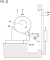
- FIG. 22 is a schematic cross-sectional diagram illustrating one part of the turret lathe 1A in the first embodiment.
- FIG. 23 is a flowchart showing one example of the tool preparation method in the first embodiment.
- FIG. 24 is a flowchart showing one example of the tool preparation method in the first embodiment.
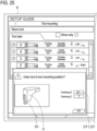
- FIG. 25 is a diagram illustrating how a fourth operation pattern is made selectable.
- FIG. 26 is a diagram illustrating how a nose position is measured.
- the turret lathe 1A in the first embodiment includes a turret E that has a plurality of mounting surfaces 6, a rotation drive unit 96 that rotates the turret E about a first axis AX, a moving unit 95 that moves the turret E, a controller 2, and a measurement unit 97.
- the controller 2 controls control targets including the rotation drive unit 96 and moving unit 95.
- the measurement unit 97 measures the nose positions.
- the turret lathe 1A may include a display 4.
- a first determination processing M1 is carried out in a first step ST1.
- the first step ST1 is a first determination step.
- the designated tool 50 is not attached to the designated mounting surface 60. Therefore, in the example depicted in FIG. 4 , the result of the first determination processing M1 indicates that the designated tool 50 is not attached to the designated mounting surface 60 (in other words, the result of the first determination processing M1 in FIG. 3 will be "No").
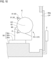
- the designated tool 50 is attached to the designated mounting surface 60. Therefore, in the example depicted in FIG. 10 , the result of the first determination processing M1 indicates that the designated tool 50 is attached to the designated mounting surface 60 (in other words, the result of the first determination processing M1 in FIG. 3 will be "Yes").
- a specific operation pattern (F1 or F2) is selected from among a plurality of operation patterns in a second step ST2.
- the second step ST2 is a selection step.
- a specific operation pattern (F1 or F2) is selected from among a plurality of operation patterns based on the result of the first determination processing M1. This selection is made by the controller 2.
- the plurality of operation patterns includes at least a first operation pattern F1 and a second operation pattern F2.
- the first operation pattern F1 is executed when the result of the first determination processing M1 is "No," in other words, when the result indicates that the designated tool 50 is not attached to the designated mounting surface 60.
- the designated tool 50 not being attached to the designated mounting surface 60 means that the designated tool 50 is in a condition before being attached to the designated mounting surface 60.
- the designated tool 50 being in a condition before being attached to the designated mounting surface 60 means that the designated tool 50 is either (1) in a condition before being attached to the turret E, or (2) attached to one of the plurality of mounting surfaces 6 of the turret E other than the designated mounting surface 60.
- the second operation pattern F2 is executed when the result of the first determination processing M1 is "Yes,” in other words, when the result indicates that the designated tool 50 is attached to the designated mounting surface 60.
- a control command is sent in a third step ST3 so that the selected specific operation pattern (F1 or F2) is executed.
- the third step ST3 is a step of sending a control command.
- control commands are sent to the rotation drive unit 96 and the moving unit 95, so that the selected specific operation pattern (F1 or F2) is executed.
- the control commands are sent by the controller 2.
- FIG. 4 to FIG. 9 illustrate one example of how the first operation pattern F1 is executed.
- the first operation pattern F1 includes rotating the turret E about the first axis AX for the designated mounting surface 60 to be brought to an indexed mounting position P1 before the designated tool 50 is attached to the designated mounting surface 60.
- the turret E is rotated by the rotation drive unit 96 that receives a control command from the controller 2.
- data 351a for specifying the indexed mounting position P1 is preferably stored in a memory 3 of the turret lathe 1A in advance.
- the indexed mounting position P1 should preferably be located where the operator has easy access.
- the designated mounting surface 60 positioned at the indexed mounting position P1 allows the operator to readily perform the operation of mounting the designated tool 50 on the designated mounting surface 60.
- the indexed mounting position P1 serves also as an indexed disengaging position for disengaging the non-designated tool 5' from the designated mounting surface 60.
- the controller 2 may present an image Q3 on a display 4 prompting to mount the designated tool 50 in response to the designated mounting surface 60 having reached the indexed mounting position P1 (see FIG. 6 ).
- Such an image Q3 being presented on the display 4 during the execution of the first operation pattern F1 helps the operator mount the designated tool 50 on the designated mounting surface 60 at the appropriate times.
- the image Q3 prompting to mount the designated tool 50 includes a message MG prompting to mount the designated tool 50.
- the image Q3 prompting to mount the designated tool 50 includes recommended relative position data DT for the designated tool 50 relative to the tool holding unit H. More specifically, the image Q3 prompting to mount the designated tool 50 includes a recommended value DT1 of overhang for the designated tool 50 relative to the tool holding unit H along the longitudinal direction of the designated tool 50. In this case, the operator can mount the designated tool 50 on the tool holding unit H such that the designated tool 50 extends from the tool holding unit H by the recommended value DT1. This allows the operator to efficiently perform the operation of mounting the designated tool 50 on the tool holding unit H.
- the image Q may be an indication that prompts to mount both of the designated tool 50 and the tool holding unit H for holding the designated tool 50.
- FIG. 7 shows the state after the designated tool 50 has been attached to the designated mounting surface 60.
- the first operation pattern F1 includes rotating the turret E about the first axis AX for the designated mounting surface 60 to be brought to an indexed position P2 for nose position measurement after the designated tool 50 has been attached to the designated mounting surface 60.
- the turret E is rotated by the rotation drive unit 96 that receives a control command from the controller 2.
- data 352a for specifying the indexed position P2 for nose position measurement is preferably stored in the memory 3 of the turret lathe 1A in advance.
- the indexed position P2 for nose position measurement should preferably be located relatively close to a contact surface 971c of the measurement unit 97.
- the first operation pattern F1 includes a measurement of the position of the nose 50e of the designated tool 50 with the measurement unit 97.
- the step of measuring the position of the nose 50e of the designated tool 50 will be referred to as the "measurement step.”
- the first operation pattern F1 may include moving the entire turret E to bring the nose 50e of the designated tool 50 to a wait position close to the contact surface 971c of the measurement unit 97. This movement of the entire turret E is carried out by the moving unit 95 that receives a control command from the controller 2.
- the first operation pattern F1 may include moving the entire turret E toward the contact surface 971c to bring the nose 50e of the designated tool 50 into contact with the contact surface 971c of the measurement unit 97. This movement of the entire turret E is carried out by the moving unit 95 that receives a control command from the controller 2.
- the first operation pattern F1 (more specifically, the measurement step) may include moving the contact surface 971c of the measurement unit 97 toward the nose 50e so that the contact surface 971c makes contact with the nose 50e of the designated tool 50.
- the measurement unit 97 measures the position of the turret E when the nose 50e of the designated tool 50 attached to the designated mounting surface 60 makes contact with the contact surface 971c of the measurement unit 97 to determine the relative position of the nose 50e of the designated tool 50 relative to a reference position of the turret E. The position of the nose 50e of the designated tool 50 is thus measured.
- the contact surface 971c may be omitted when the measurement unit 97 is a non-contact type measurement device (e.g., a device that measures the position of the nose using a camera or the like).
- the block 97c (e.g., see FIG.
- the turret lathe 1A may include a mechanism that stores the block 97c and arm 97f in a storage area outside of the preparation operation area.
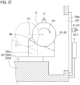
- the block 97c that defines the contact surface 971c is located in the retracted position and therefore not shown in FIG. 4 , FIG. 5 , FIG. 7 , FIG. 10 , FIG. 13 , FIG. 14 , FIG. 16 , FIG. 17 , FIG. 18 , FIG. 22 , and FIG. 37 .
- FIG. 10 to FIG. 12 illustrate one example of how the second operation pattern F2 is executed.
- the second operation pattern F2 includes rotating the turret E about the first axis AX for the designated mounting surface 60 with the designated tool 50 mounted thereon to be directly brought to the indexed position P2 for nose position measurement.
- the turret E is rotated by the rotation drive unit 96 that receives a control command from the controller 2.
- the second operation pattern F2 includes a measurement of the position of the nose 50e of the designated tool 50 with the measurement unit 97.
- the second operation pattern F2 may include moving the entire turret E to bring the nose 50e of the designated tool 50 to a wait position close to the contact surface 971c of the measurement unit 97. This movement of the entire turret E is carried out by the moving unit 95 that receives a control command from the controller 2.
- the second operation pattern F2 may include moving the entire turret E toward the contact surface 971c to bring the nose 50e of the designated tool 50 into contact with the contact surface 971c of the measurement unit 97. This movement of the entire turret E is carried out by the moving unit 95 that receives a control command from the controller 2.
- the second operation pattern F2 (more specifically, the measurement step) may include moving the contact surface 971c of the measurement unit 97 toward the nose 50e so that the contact surface 971c makes contact with the nose 50e of the designated tool 50.
- the measurement unit 97 measures the position of the turret E when the nose 50e of the designated tool 50 attached to the designated mounting surface 60 makes contact with the contact surface 971c of the measurement unit 97 to determine the relative position of the nose 50e of the designated tool 50 relative to the reference position of the turret E.
- the first operation pattern F1 is executed when the designated tool 50 is not attached to the designated mounting surface 60.
- the first operation pattern F1 includes bringing the designated mounting surface 60 to the indexed mounting position P1. This allows the operator to readily perform the operation of mounting the designated tool 50 on the designated mounting surface 60.
- the second operation pattern F2 is executed when the designated tool 50 is attached to the designated mounting surface 60.
- the second operation pattern F2 includes bringing the designated mounting surface 60 directly to the indexed position P2 for nose position measurement.
- the procedure including the measurement of the nose position of the designated tool 50 can be performed quickly.
- the turret lathe 1A in the first embodiment will be described with reference to FIG. 1 to FIG. 26 .
- the turret lathe 1A in the first embodiment includes the turret E, rotation drive unit 96, moving unit 95, measurement unit 97, and controller 2.
- the turret lathe 1A may include the display 4.
- the turret E has a plurality of mounting surfaces 6. Each of the plurality of mounting surfaces 6 allows a tool to be mounted thereon.
- the rotation drive unit 96 rotates the turret E about the first axis AX.
- the moving unit 95 moves the turret E (more specifically, the entire turret E).
- the measurement unit 97 has the contact surface 971c for the nose Be of a tool to touch.
- the measurement unit 97 measures the position of the nose Be of a tool. More specifically, the measurement unit 97 measures the position of the turret E when the nose Be of the tool attached to the turret E makes contact with the contact surface 971c of the measurement unit 97 to determine the relative position of the nose Be of the tool relative to the reference position of the turret E.
- the contact surface 971c may be omitted when the measurement unit 97 is a non-contact type measurement device (e.g., a device that measures the position of the nose using a camera or the like).
- the controller 2 controls a plurality of control targets (e.g., the rotation drive unit 96, moving unit 95, and others). As illustrated in FIG. 2 , the controller 2 includes at least one processor 2a (e.g., at least one CPU). The controller 2 may be divided into several units. In other words, several units may cooperate to function as the controller 2.
- processor 2a e.g., at least one CPU
- the turret lathe 1A (more specifically, the controller 2) includes the memory 3, display 4, and a communication circuit 12.
- the memory 3, display 4, and communication circuit 12 are all included in the controller 2.
- at least a part of each of the memory 3, display 4, and communication circuit 12 may be provided separately from the controller 2, and configured to be able to communicate with the controller 2.
- the memory 3 stores a program 39 and data.
- the memory 3 is a storage medium readable by a processor 2a.
- the memory 3 may for example be a non-volatile or volatile semiconductor memory such as a RAM, ROM, or flash memory, or a magnetic disc, or any other types of memories.
- the memory 3 may be distributed in several locations.
- the memory that stores data may be provided separately from the memory that stores the program 39.
- a part of the memory 3 may be located away from the communication circuit 12.
- a part of the memory 3 may provide the processor 2a with a part of the program 39 or a part of the data via the communication circuit 12 when the processor 2a executes the program 39.
- the turret lathe 1A may include an input unit 11.
- the input unit 11 may be integrated into the display 4 (more specifically, the display 4 may be a display 40 with a touchscreen including a built-in input unit 11a).
- the turret lathe 1A may include input units 11b provided separately from the display 4 (such as, for example, a button, switch, lever, pointing device, keyboard, and so on).
- the processor 2a, memory 3, communication circuit 12, display 4, and/or input unit 11 are all interconnected via a bus 13.
- the controller 2 performs the first determination processing M1 (see FIG. 3 ) to determine whether or not a designated tool 50 is attached to a designated mounting surface 60, which is one of the plurality of mounting surfaces 6 of the turret E.
- the controller 2 selects a specific operation pattern from among a plurality of operation patterns including a first operation pattern F1 and a second operation pattern F2 based on the result of the first determination processing M1.
- the controller 2 also sends control commands CR to the rotation drive unit 96 and the moving unit 95, so that the selected specific operation pattern is executed.
- the plurality of operation patterns includes at least the first operation pattern F1 and the second operation pattern F2.
- the first operation pattern F1 is executed when the result of the first determination processing M1 indicates that the designated tool 50 is not attached to the designated mounting surface 60.
- the second operation pattern F2 is executed when the result of the first determination processing M1 indicates that the designated tool 50 is attached to the designated mounting surface 60.
- the first operation pattern F1 includes rotating the turret E about the first axis AX for the designated mounting surface 60 to be brought to an indexed mounting position P1 before the designated tool 50 is attached to the designated mounting surface 60. More specifically, the first operation pattern F1 includes rotating the turret E about the first axis AX by the rotation drive unit 96 that receives a control command from the controller 2 for the designated mounting surface 60 before the designated tool 50 is mounted thereon to be brought to the indexed mounting position P1.
- data 351a for specifying the indexed mounting position P1 is preferably stored in the memory 3 in advance.
- the indexed mounting position P1 should preferably be located where the operator has easy access.
- the designated mounting surface 60 positioned at the indexed mounting position P1 allows the operator to readily perform the operation of mounting the designated tool 50 on the designated mounting surface 60.
- the controller 2 may present an image Q3 on the display 4 prompting to mount the designated tool 50 in response to the designated mounting surface 60 having reached the indexed mounting position P1 (see FIG. 6 ).
- Such an image Q3 prompting to mount the designated tool 50 when presented on the display 4 during the execution of the first operation pattern F1, helps the operator mount the designated tool 50 on the designated mounting surface 60 at the appropriate times. Since the image Q3 prompting to mount the designated tool 50 has already been described in detail, repetitive description of the image Q3 will be omitted.
- FIG. 7 shows the state after the designated tool 50 has been attached to the designated mounting surface 60.
- the first operation pattern F1 includes rotating the turret E about the first axis AX for the designated mounting surface 60 to be brought to an indexed position P2 for nose position measurement after the designated tool 50 has been attached to the designated mounting surface 60. More specifically, the first operation pattern F1 includes rotating the turret E about the first axis AX by the rotation drive unit 96 that receives a control command from the controller 2 for the designated mounting surface 60 with the designated tool 50 mounted thereon to be brought to the indexed position P2 for nose position measurement.
- data 352a for specifying the indexed position P2 for nose position measurement is preferably stored in the memory 3 in advance.
- the indexed position P2 for nose position measurement should preferably be located relatively close to the contact surface 971c of the measurement unit 97.
- the first operation pattern F1 includes measuring the position of the nose 50e of the designated tool 50 using the measurement unit 97.
- the first operation pattern F1 may include moving the entire turret E to bring the nose 50e of the designated tool 50 to a wait position close to the contact surface 971c of the measurement unit 97. More specifically, the first operation pattern F1 may include moving the entire turret E by the moving unit 95 that receives a control command from the controller 2 to bring the nose 50e of the designated tool 50 to a wait position close to the contact surface 971c of the measurement unit 97.
- the first operation pattern F1 may include moving the entire turret E toward the contact surface 971c to bring the nose 50e of the designated tool 50 into contact with the contact surface 971c of the measurement unit 97. More specifically, the first operation pattern F1 may include moving the entire turret E by the moving unit 95 that receives a control command from the controller 2 to bring the nose 50e of the designated tool 50 into contact with the contact surface 971c of the measurement unit 97.
- the first operation pattern F1 may include moving the contact surface 971c of the measurement unit 97 toward the nose 50e so that the contact surface 971c makes contact with the nose 50e of the designated tool 50. Further alternatively, the first operation pattern F1 may include measuring the position of the nose 50e of the designated tool 50 in a non-contact manner.
- the measurement unit 97 measures the position of the turret E when the nose 50e of the designated tool 50 attached to the designated mounting surface 60 makes contact with the contact surface 971c of the measurement unit 97 to determine the relative position of the nose 50e of the designated tool 50 relative to the reference position of the turret E. The position of the nose 50e of the designated tool 50 is thus measured.
- the second operation pattern F2 includes rotating the turret E about the first axis AX for the designated mounting surface 60 with the designated tool 50 mounted thereon to be directly brought to the indexed position P2 for nose position measurement. More specifically, the second operation pattern F2 includes rotating the turret E about the first axis AX by the rotation drive unit 96 that receives a control command from the controller 2 for the designated mounting surface 60 with the designated tool 50 mounted thereon to be directly brought to the indexed position P2 for nose position measurement.
- the second operation pattern F2 includes measuring the position of the nose 50e of the designated tool 50 using the measurement unit 97.
- the second operation pattern F2 may include moving the entire turret E to bring the nose 50e of the designated tool 50 to a wait position close to the contact surface 971c of the measurement unit 97. More specifically, the second operation pattern F2 may include moving the entire turret E by the moving unit 95 that receives a control command from the controller 2 to bring the nose 50e of the designated tool 50 to a wait position close to the contact surface 971c of the measurement unit 97.
- the second operation pattern F2 may include moving the entire turret E toward the contact surface 971c to bring the nose 50e of the designated tool 50 into contact with the contact surface 971c of the measurement unit 97. More specifically, the second operation pattern F2 may include moving the entire turret E by the moving unit 95 that receives a control command from the controller 2 to bring the nose 50e of the designated tool 50 into contact with the contact surface 971c of the measurement unit 97.
- the second operation pattern F2 may include moving the contact surface 971c of the measurement unit 97 toward the nose 50e so that the contact surface 971c makes contact with the nose 50e of the designated tool 50. Further alternatively, the second operation pattern F2 may include measuring the position of the nose 50e of the designated tool 50 in a non-contact manner.
- the measurement unit 97 measures the position of the turret E when the nose 50e of the designated tool 50 attached to the designated mounting surface 60 makes contact with the contact surface 971c of the measurement unit 97 to determine the relative position of the nose 50e of the designated tool 50 relative to the reference position of the turret E. The position of the nose 50e of the designated tool 50 is thus measured.
- the first operation pattern F1 is executed when the designated tool 50 is not attached to the designated mounting surface 60.
- the first operation pattern F1 includes bringing the designated mounting surface 60 to the indexed mounting position P1. This allows the operator to readily perform the operation of mounting the designated tool 50 on the designated mounting surface 60.
- the second operation pattern F2 is executed when the designated tool 50 is attached to the designated mounting surface 60.
- the second operation pattern F2 brings the designated mounting surface 60 directly to the indexed position P2 for nose position measurement.
- the procedure including the measurement of the nose position of the designated tool 50 can be performed quickly.
- the turret lathe 1A may include an access opening OP that allows the operator to access the turret E.
- the turret lathe 1A may include a door 99a that can close this access opening OP.
- the first operation pattern F1 includes rotating the turret E about the first axis AX (see arrow AR1) for the designated mounting surface 60 to be brought to the indexed mounting position P1 before the designated tool 50 is attached to the designated mounting surface 60.
- the turret is rotated by the rotation drive unit 96 that receives a control command from the controller 2.
- the first operation pattern F1 includes moving the entire turret E to bring the designated mounting surface 60 closer to the access opening OP before the designated tool 50 is attached to the designated mounting surface 60. More specifically, the first operation pattern F1 includes moving the entire turret E by the moving unit 95 that receives a control command from the controller 2 for the designated mounting surface 60 before the designated tool 50 is mounted thereon to come closer to the access opening OP. The first operation pattern F1 may include moving the entire turret E by the moving unit 95 that receives a control command from the controller 2 to bring the reference position G1 of the turret to a first position P9 that is relatively close to the access opening OP. Data 361a for specifying the first position P9 should preferably be stored in the memory 3 in advance.
- first operation pattern F1 either of the operation of rotating the turret E about the first axis AX (see arrow AR1) and the operation of moving the entire turret E closer to the access opening OP (see arrow AR2) may be carried out first.
- the operation of rotating the turret E about the first axis AX (see arrow AR1) and the operation of moving the entire turret E closer to the access opening OP (see arrow AR2) in the first operation pattern F1 may be carried out simultaneously.
- the block 97c (see FIG.
- the block 97c and arm 97f should preferably be moved from the advanced position to a retracted position before the operation of rotating the turret E (see arrow AR1 in FIG. 13 ) and the operation of moving the entire turret E (see arrow AR2 in FIG. 13 ) are carried out.
- the block 97c and arm 97f may be moved from the advanced position to the retracted position after the measurement of the nose position of a previous designated tool has been completed. In these cases, the block 97c and arm 97f are moved from the advanced position to the retracted position after the mounting of the designated tool 50 on the designated mounting surface 60 and before the measurement of the nose position of the designated tool 50 in the first operation pattern F1.
- the first operation pattern F1 may include: (1) moving the door 99a from a closed position P7 where it closes the access opening OP (see FIG. 5 ) to an open position P8 where it opens the access opening OP (see FIG. 7 or FIG. 13 ) after the designated mounting surface 60 has been brought to the indexed mounting position P1; and (2) moving the door 99a from the open position P8 where it opens the access opening OP (see FIG. 7 or FIG. 13 ) to the closed position P7 where it closes the access opening OP (see FIG. 8 ) after the designated tool 50 has been attached to the designated mounting surface 60.
- the door 99a will close the access opening OP before and after the operation of mounting the designated tool 50 on the designated mounting surface 60. This allows the operator to perform the preparation operation before the machining of the workpiece more safely.
- the plurality of designated tools 50 includes a first designated tool 51 and a second designated tool 52 .
- the plurality of designated tools 50 includes (1) a first designated tool 51 attached to a first designated mounting surface 61, with its nose position not measured yet, and (2) a second designated tool 52 before it is attached to a second designated mounting surface 62, with its nose position not measured yet.
- the controller 2 sends control commands to the rotation drive unit 96 and the moving unit 95 (see FIG. 15 ), so that the first operation pattern F1 and second operation pattern F2 are both executed.
- the first determination processing M1 mentioned before includes determining whether or not the first designated tool 51 is attached to the first designated mounting surface 61 that is one of the plurality of mounting surfaces 6.
- the controller 2 selects the second operation pattern F2 from among a plurality of operation patterns based on the result of the first determination processing M1 about the first designated tool 51.
- the controller 2 also sends control commands to the rotation drive unit 96 and the moving unit 95, so that the selected second operation pattern F2 is executed.
- the second operation pattern F2 includes rotating the turret E about the first axis AX for the first designated mounting surface 61 with the first designated tool 51 mounted thereon to be directly brought to a first indexed position P2-1 for nose position measurement.
- the second operation pattern F2 may include moving the entire turret E to bring the nose 51e of the first designated tool 51 into contact with the contact surface 971c of the measurement unit 97.
- the measurement unit 97 measures the position of the turret E when the nose 51e of the first designated tool 51 attached to the first designated mounting surface 61 makes contact with the contact surface 971c of the measurement unit 97, to determine the relative position of the nose 51e of the first designated tool 51 relative to the reference position of the turret E. The position of the nose 51e of the first designated tool 51 is thus measured.
- the first determination processing M1 mentioned before includes determining whether or not the second designated tool 52 is attached to the second designated mounting surface 62 that is one of the plurality of mounting surfaces 6.
- the controller 2 selects the first operation pattern F1 from among a plurality of operation patterns based on the result of the first determination processing M1 about the second designated tool 52.
- the controller 2 also sends control commands to the rotation drive unit 96 and the moving unit 95, so that the selected first operation pattern F1 is executed.
- FIG. 16 to FIG. 19 illustrate one example of how the first operation pattern F1 is executed.
- the first operation pattern F1 includes moving the entire turret E (see arrow AR3) to bring the second designated mounting surface 62 closer to the access opening OP before the second designated tool 52 is attached to the second designated mounting surface 62.
- the turret is moved by the moving unit 95 that receives a control command from the controller 2.
- the first operation pattern F1 includes rotating the turret E about the first axis AX for the second designated mounting surface 62 to be brought to a second indexed mounting position P1-2 before the second designated tool 52 is attached to the second designated mounting surface 62.
- the turret is rotated by the rotation drive unit 96 that receives a control command from the controller 2.
- the second indexed mounting position P1-2 may be the same as the indexed mounting position P1 described in the foregoing (see FIG. 5 ), or different from the previously described indexed mounting position P1.
- the first operation pattern F1 may include moving the door 99a from the closed position P7 to the open position P8 before the second designated tool 52 is attached to the second designated mounting surface 62.
- the first operation pattern F1 may include moving the door 99a from the open position P8 to the closed position P7 after the second designated tool 52 has been attached to the second designated mounting surface 62.
- the door 99a is moved by the door moving unit 99b that receives a control command from the control command 2.
- the controller 2 may present an image on the display 4 prompting to mount the second designated tool 52 (more specifically, an image similar to the image Q3 shown in FIG. 6 ) in response to the second designated mounting surface 62 having reached the second indexed mounting position P1-2 (see FIG. 17 ) during the execution of the first operation pattern F1.
- FIG. 18 shows the state after the second designated tool 52 has been attached to the second designated mounting surface 62.
- the first operation pattern F1 includes rotating the turret E about the first axis AX for the second designated mounting surface 62 to be brought to a second indexed position P2-2 for nose position measurement after the second designated tool 52 has been attached to the second designated mounting surface 62.
- the turret is rotated by the rotation drive unit 96 that receives a control command from the controller 2.
- the second indexed position P2-2 for nose position measurement may be the same as the first indexed position P2-1 for nose position measurement described in the foregoing (see FIG. 11 ), or different from the previously described first indexed position P2-1 for nose position measurement.
- the first operation pattern F1 includes measuring the position of the nose 52e of the second designated tool 52 using the measurement unit 97.
- the first operation pattern F1 may include moving the entire turret E toward the contact surface 971c to bring the nose 52e of the second designated tool 52 into contact with the contact surface 971c of the measurement unit 97.
- the turret is moved by the moving unit 95 that receives a control command from the controller 2.
- the measurement unit 97 measures the position of the turret E when the nose 52e of the second designated tool 52 attached to the second designated mounting surface 62 makes contact with the contact surface 971c of the measurement unit 97, to determine the relative position of the nose 52e of the second designated tool 52 relative to the reference position of the turret E. The position of the nose 52e of the second designated tool 52 is thus measured.
- a designated tool 50 e.g., first designated tool 51
- a specific designated mounting surface 60 e.g., first designated mounting surface 61
- another designated tool e.g., second designated tool 52
- another specific designated mounting surface e.g., second designated mounting surface 62
- the turret lathe 1A in the first embodiment allows for efficient measurement of the nose positions of the respective designated tools 50.
- the first designated tool 51 is attached to the first designated mounting surface 61, while the second designated tool 52 is not attached to the second designated mounting surface 62.
- the turret lathe 1A in the first embodiment, or the tool preparation method according to the first embodiment, are applicable also to other examples.
- the controller 2 can make the following selections when the plurality of designated tools 50 includes a first designated tool 51 and a second designated tool 52 (in other words, two or more designated tools).
- the controller 2 selects the first operation pattern F1 as the operation pattern for the first designated tool 51, and (2) when the result of the first determination processing M1 indicates that the first designated tool 51 is attached to the first designated mounting surface 61, the controller 2 selects the second operation pattern F2 as the operation pattern for the first designated tool 51.
- the controller 2 selects the first operation pattern F1 as the operation pattern for the second designated tool 52, and (4) when the result of the first determination processing M1 indicates that the second designated tool 52 is attached to the second designated mounting surface 62, the controller 2 selects the second operation pattern F2 as the operation pattern for the second designated tool 52.
- the controller 2 can select a specific operation pattern from a plurality of operation patterns for each designated tool according to the flowchart shown in FIG. 21 .
- the controller 2 may then send control commands to the rotation drive unit 96 and the moving unit 95, so that the selected specific operation pattern is executed for each designated tool according to the flowchart shown in FIG. 21 .
- the indexed mounting position P1 may be set in accordance with the tool type.
- the memory 3 may store data 351a-1 specifying the first indexed mounting position P1-1 (see FIG. 5 ) for a first type of tool, and data 351a-3 specifying another indexed mounting position different from the first indexed mounting position P1-1 (hereinafter referred to as "third indexed mounting position P1-3, see FIG. 22 ) for a second type of tool.
- the tool type of the designated tool 50 is a first type Ty1.
- the first operation pattern F1 includes rotating the turret E about the first axis AX for the designated mounting surface 60 to be brought to the first indexed mounting position P1-1.
- the first type Ty1 may mean, for example, a specific type of turning tool.
- the tool type of the designated tool 50 is a second type Ty2.
- the first operation pattern F1 includes rotating the turret E about the first axis AX for the designated mounting surface 60 to be brought to a third indexed mounting position P1-3 different from the first indexed mounting position P1-1.
- the second type Ty2 may mean, for example, a specific type of milling tool.
- the controller 2 may be configured to execute a second determination processing M2 to determine whether or not the nose position of a designated tool 50 has already been measured.
- the tool preparation method includes executing the second determination processing M2 of determining whether or not the nose position of the designated tool 50 has already been measured.
- the second determination processing M2 is executed after the first determination processing M1 (more specifically, when the result of the first determination processing M1 indicates that the designated tool 50 is attached to the designated mounting surface 60).
- the second determination processing M2 may be executed before the first determination processing M1.
- the controller 2 selects the second operation pattern F2.
- the controller 2 also sends control commands to the rotation drive unit 96 and the moving unit 95, so that the selected second operation pattern F2 is executed. In this case, the second operation pattern F2 is not executed to the designated tool 50 whose nose position has already been measured. Thus unnecessary measurement work is avoided.
- the plurality of operation patterns for the controller 2 to select from includes a third operation pattern F3 that skips measurement of the nose position of the designated tool 50.
- the controller 2 selects the third operation pattern F3.
- the third operation pattern F3 is thus selected to avoid double measurement of the nose position of a designated tool 50 that is already attached to the designated mounting surface 60 and whose nose position has already been measured.
- the plurality of operation patterns for the controller 2 to select from may include a fourth operation pattern.
- the fourth operation pattern F4 is an operation pattern that can be selected when the result of the first determination processing M1 indicates that the designated tool 50 is not attached to the designated mounting surface 60 (result of the first determination processing M1: "No").
- the fourth operation pattern is an operation pattern that can be selected instead of the first operation pattern F1.
- the measurement of the nose position of a specific designated tool 50 may be omitted by not selecting the specific designated tool 50 in a second screen Q2 to be described later (in other words, the fourth operation pattern may be selected instead of the first operation pattern F1 for the specific designated tool 50 by not selecting the specific designated tool 50 in the second screen Q2).
- the fourth operation pattern includes rotating the turret E about the first axis AX (see FIG. 5 ) for the designated mounting surface 60 to be brought to the indexed mounting position P1 before the designated tool 50 is attached to the designated mounting surface 60.
- the turret is rotated by the rotation drive unit 96 that receives a control command from the controller 2.
- the fourth operation pattern may include moving the entire turret E to bring the designated mounting surface 60 closer to the access opening OP before the designated tool 50 is attached to the designated mounting surface 60 (see FIG. 13 ).
- the fourth operation pattern skips the processing of bringing the designated mounting surface 60 to the indexed position P2 for nose position measurement P2.
- the fourth operation pattern that can be selected instead of the first operation pattern F1 increases the number of options for the operator.
- the first operation pattern F1 and second operation pattern F2 may each include measuring the position of the nose 50e of the designated tool 50 (e.g., first designated tool 51 or second designated tool 52) with the measurement unit 97 in a direction (in other words, the z-axis direction) parallel to the first axis AX that is the rotation axis of the turret E (see arrow AR4).
- first operation pattern F1 and second operation pattern F2 may each include moving the turret E in a direction parallel to the first axis AX to bring the nose 50e of the designated tool 50 into contact with a first contact surface 971c-1 of the measurement unit 97.
- the turret is moved by the moving unit 95 that receives a control command from the controller 2.
- the controller 2 calculates the relative position of the nose 50e of the designated tool 50 relative to the reference position G1 of the turret E in the direction parallel to the first axis AX based on the position of the turret E when the nose 50e of the designated tool 50 makes contact with the first contact surface 971c-1 (in other words, the measurement unit 97 measures the position of the nose 50e of the designated tool 50 in the direction parallel to the first axis AX).
- first operation pattern F1 and second operation pattern F2 may each include measuring the position of the nose 50e of the designated tool 50 (e.g., first designated tool 51 or second designated tool 52) with the measurement unit 97 in a direction (more specifically, the x-axis direction) perpendicular to the first axis AX (see arrow AR5).
- first operation pattern F1 and second operation pattern F2 may each include moving the turret E in a direction perpendicular to the first axis AX to bring the nose 50e of the designated tool 50 into contact with a second contact surface 971c-2 of the measurement unit 97.
- the turret is moved by the moving unit 95 that receives a control command from the controller 2.
- the controller 2 calculates the relative position of the nose 50e of the designated tool 50 relative to the reference position G1 of the turret E in the direction perpendicular to the first axis AX based on the position of the turret E when the nose 50e of the designated tool 50 makes contact with the second contact surface 971c-2 (in other words, the measurement unit 97 measures the position of the nose 50e of the designated tool 50 in the direction perpendicular to the first axis AX).
- FIG. 27 is a schematic perspective diagram illustrating the turret lathe 1B in the second embodiment.
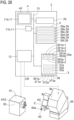
- FIG. 28 is a block diagram illustrating a hardware configuration example of the controller 2.
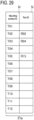
- FIG. 29 is a diagram illustrating one example of first data 31a stored in the memory 3.
- FIG. 30 is a diagram illustrating one example of second data 32a stored in the memory 3.
- FIG. 31 is a diagram illustrating one example of third data 33a stored in the memory 3.
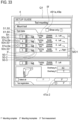
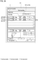
- FIG. 32 to FIG. 35 are diagrams each illustrating a first image Q1 shown on the display 4.
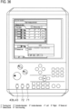
- FIG. 36 is a diagram illustrating one example of an outer look of the controller 2.
- FIG. 29 is a diagram illustrating one example of first data 31a stored in the memory 3.
- FIG. 30 is a diagram illustrating one example of second data 32a stored in the memory 3.
- FIG. 31 is a diagram illustrating one example of third data 33a stored in the memory 3.
- FIG. 32 to FIG. 35 are diagrams each illustrating a first image Q1 shown on
- FIG. 37 is a schematic cross-sectional diagram illustrating one part of the turret lathe 1B in the second embodiment.
- FIG. 38 to FIG. 40 are diagrams each illustrating a second image Q2 shown on the display 4.
- FIG. 41 and FIG. 42 are diagrams each illustrating a measurement macro 38t shown on the display 4.
- the turret lathe 1B in the second embodiment includes: (1) a turret E that has a plurality of mounting surfaces 6; (2) a rotation drive unit 96 that rotates the turret E about a first axis AX; (3) a moving unit 95 that moves the turret E; (4) a measurement unit 97 that measures the position of the tool nose; and (5) a controller 2.
- the controller 2 performs the first determination processing M1 of determining whether or not a designated tool 50 is attached to a designated mounting surface 60 that is one of the plurality of mounting surfaces 6, selects a specific operation pattern from a plurality of operation patterns based on the results of the first determination processing M1, and sends control commands to the rotation drive unit 96 and the moving unit 95 so that the selected operation pattern is executed.
- the turret E, rotation drive unit 96, moving unit 95, measurement unit 97, and controller 2 have already been described in the first embodiment, and therefore repetitive descriptions of these elements will be omitted.
- the first determination processing M1 executed by the controller 2, and the first operation pattern F1 and second operation pattern F2 that can be selected by the controller 2, are the same as the first determination processing M1, first operation pattern F1, and second operation pattern F2 that have been described in the first embodiment.
- this second determination processing M2 will be the same as the second determination processing M2 that has been described in the first embodiment.
- this third operation pattern (or fourth operation pattern) will be the same as the third operation pattern F3 (or fourth operation pattern F4) that have been described in the first embodiment. Therefore, repetitive descriptions of the first determination processing M1, second determination processing M2, first operation pattern F1, second operation pattern F2, third operation pattern F3, and fourth operation pattern will be omitted in the second embodiment.
- the turret lathe 1B in the second embodiment provides the same effects as those of the turret lathe 1A according to the first embodiment.
- the turret lathe 1B in the second embodiment may include the memory 3, display 4, input unit 11, and communication circuit 12.
- the memory 3, display 4, input unit 11, and communication circuit 12 have already been described in the first embodiment, and therefore repetitive descriptions of these elements will be omitted.
- the moving unit 95 includes a first moving unit 95a that moves the turret E in a first direction DR1 parallel to the horizontal plane. Additionally, the moving unit 95 may include a second moving unit 95b that moves the turret E in a second direction DR2 parallel to the horizontal plane and perpendicular to the first direction DR1. The moving unit 95 may further include a third moving unit 95c that changes the height of the turret E. The moving unit 95 moves the turret E to bring a tool attached to the turret E into contact with a workpiece. Thus the workpiece is machined with the tool. In the example depicted in FIG. 27 , the third moving unit 95c moves the turret E in the X-axis direction to change the height of the turret E.
- the measurement unit 97 has a block 97c that defines the contact surface 971c for the nose of a tool to touch.
- the measurement unit 97 calculates the position of the turret E when the nose and the contact surface 971c make contact with each other. This calculation is performed by the controller 2. In other words, the controller 2 configures a part of the measurement unit 97.
- the controller 2 calculates the relative position of the nose relative to the reference position of the turret E based on the position of the turret E when the nose makes contact with the contact surface 971c (in other words, the controller 2 measures the position of the nose).
- the memory 3 stores a machining program 39e.
- the machining program 39e is executed by a computer (more specifically, at least one processor 2a included in the controller 2) to control the movement of the tool.
- the controller 2 executes the machining program 39e stored in the memory 3 to generate control commands.
- the generated control commands are sent to various control targets (e.g., the rotation drive unit 96, moving unit 95, rotation drive device 92, etc.) via the communication circuit 12.
- the rotation drive unit 96 having received a control command from the controller 2 executing the machining program 39e, rotates the turret E about the first axis AX.
- the moving unit 95 having received a control command from the controller 2, moves the entire turret E to bring the nose 50e of the designated tool 50 attached to the turret E into contact with the workpiece.
- the rotation drive device 92 having received a control command from the controller 2 executing the machining program 39e, rotates the workpiece held on the chuck 93 via the jaws 94 about the second axis AX2.
- the nose 50e of the designated tool 50 moves relative to the workpiece in contact therewith, so that the workpiece is machined.
- the memory 3 stores first data 31a.
- the first data 31a is data that associates the mounting surfaces 6 of the turret E with the tools 5 attached to respective mounting surfaces 6.
- the first data 31a may associate mounting surface identifiers 6i identifying the mounting surfaces 6 of the turret E with tool identifiers 5i identifying the tools 5 attached to the respective mounting surfaces 6, to associate the mounting surfaces 6 of the turret E with the tools 5 attached to the respective mounting surfaces 6.
- the memory 3 stores second data 32a.
- the second data 32a is data that indicates whether or not the nose positions of the respective tools 5 attached to the turret E have already been measured.
- the second data 32a determines whether or not the nose positions of the respective tools 5 attached to the turret E have already been measured by associating tool identifiers 5i that identify the tools 5 on the respective mounting surfaces 6 with the data 5m that indicates whether or not the nose positions of the tools 5 have already been measured.
- the second data 32a may include nose position data 5p acquired by measurement with the measurement unit 97.
- the second data 32a may include tool characteristic data 5f that indicates the characteristics of the tool 5.
- the memory 3 stores third data 33a.
- the third data 33a is data that associates each designated tool 50 with the designated mounting surface 60 on which the designated tool 50 should be mounted.
- the third data 33a associates designated tool identifiers 50i identifying the designated tools 50 with the mounting surface identifiers 60i identifying the designated mounting surfaces 60 on which the designated tools 50 should be mounted, to associate each designated tool 50 with the designated mounting surface 60 on which the designated tool 50 should be mounted.
- the third data 33a may include tool characteristic data 5f that indicates the characteristics of the designated tool 50.
- the memory 3 may store data 35a that specifies each of the indexed positions.
- the data 35a includes data 351a that specifies the indexed mounting position P1, and data 352a that specifies the indexed position P2 for nose position measurement.
- the data 351a that specifies the indexed mounting position P1 may include data 351a-1 that specifies a first indexed mounting position P1-1 (see FIG. 5 ), data 351a-2 that specifies a second indexed mounting position P1-2 (see FIG. 17 ), and/or data 351a-3 that specifies a third indexed mounting position P1-3 (see FIG. 22 ).
- the memory 3 may store data 361a that specifies the first position P9 (see FIG. 13 ) relatively close to the access opening OP.
- the memory 3 may store tool data 371a, workpiece data 372a (e.g., workpiece shape data, etc.), turret E reference position data 373a (e.g., origin data), and so on.
- workpiece data 372a e.g., workpiece shape data, etc.
- turret E reference position data 373a e.g., origin data
- the memory 3 may include a temporary storage region 38 that temporarily stores measurement macros 38t and the like generated by the controller 2.
- the memory 3 stores a determination program 39a.
- the controller 2 executes the determination program 39a to implement the first determination processing M1 described above.
- the controller 2 executes the first determination processing M1 based on the third data 33a that associates each designated tool 50 with the designated mounting surface 60 on which the designated tool 50 should be mounted, and the first data 31a that associates each mounting surface 6 of the turret E with the tool 5 attached to the mounting surface 6.
- the first determination processing M1 includes determining whether or not a designated tool 50 (e.g., first designated tool 51) is attached to a designated mounting surface 60 (e.g., first designated mounting surface 61), which is one of the plurality of mounting surfaces 6. Additionally, where "K" represents any natural number equal to or greater than 2, the first determination processing M1 may include determining whether or not the "K-th" designated tool is attached to the "K-th" designated mounting surface that is one of the plurality of mounting surfaces 6.
- the controller 2 may execute the determination program 39a to implement the second determination processing M2 described above. For example, the controller 2 executes the second determination processing M2 described above based on the third data 33a that associates each designated tool 50 with the designated mounting surface 60 on which the designated tool 50 should be mounted, and the second data 32a that indicates whether or not the nose positions of the respective tools 5 attached to the turret E have already been measured.
- the second determination processing M2 includes determining whether or not the nose position of a designated tool 50 (e.g., first designated tool 51) has already been measured. Additionally, where "K" represents any natural number equal to or greater than 2, the second determination processing M2 may include determining whether or not the nose position of the "K-th" designated tool has already been measured.
- the memory 3 stores a nose position measurement program 39c.
- the nose position measurement program 39c executed by the controller 2 causes the controller 2 to select a specific operation pattern from among a plurality of operation patterns based on the results of the first determination processing M1 (or the results of the first determination processing M1 and second determination processing M2).
- the nose position measurement program 39c executed by the controller 2 also causes the controller 2 to send control commands to the rotation drive unit 96 and the moving unit 95 via the communication circuit 12, so that the selected specific operation pattern is executed.
- the memory 3 stores a display program 39d.
- the processor 2a of the controller 2 executes the display program 39d to generate a first display command based on the results of the first determination processing M1.
- the generated first display command is sent to the display 4.
- the processor 2a of the controller 2 may execute the display program 39d to generate a second display command based on the results of the second determination processing M2.
- the generated second display command is sent to the display 4.
- the display 4 shows the first image Q1 in response to receiving the first display command that has been generated based on the results of the first determination processing M1 from the processor 2a.
- the first image Q1 shows whether or not the designated tool 50 is attached to the designated mounting surface 60.
- the first image Q1 includes a sub image Q1-1 indicating whether or not the first designated tool 51 is attached to the first designated mounting surface 61. Additionally, where "K" represents any natural number equal to or greater than 2, the first image Q1 may include a sub image indicating whether or not the "K-th" designated tool is attached to the "K-th" designated mounting surface. Moreover, the first image Q1 may include a sub image Q1' indicating which of the mounting surfaces of the turret E has a non-designated tool 5' that is not needed in the next machining processing (in other words, a tool that is not the designated tool) mounted thereon.
- the designated tools 50 e.g., all designated tools to be designated by the machining program 39e
- the designated tools 50 before they are attached to the designated mounting surfaces 60 are herein defined as unmounted designated tools 50n.
- the designated tools 50 that are attached to the designated mounting surfaces 60 are herein defined as mounted designated tools 50x.
- the unmounted designated tools 50n are added with an attention mark 81a (e.g., exclamation mark) in the first image Q1.
- the mounted designated tools 50x are not added with the attention mark 81a in the first image Q1.
- each designated tool 50 is an unmounted designated tool 50n or a mounted designated tool 50x based on the presence or absence of the attention mark 81a.
- the first image Q1 includes the attention marks 81a as information 8a that indicates whether or not each designated tool 50 is attached to the designated mounting surface 60.
- the first image Q1 may include some text information or highlighting as the information 8a.
- the display 4 may show an image of a switching control 49a (e.g., a check box 491a) in the above-described first image Q1.
- the controller 2 allows the switching control 49a (e.g., check box 491a) to be operated to toggle the display mode of the first image Q1 between (1) a first display mode MD1 (see FIG. 33 ) showing all the designated tools 50 and (2) a second display mode MD2 (see FIG. 34 ) showing all the unmounted designated tools 50n only and not the mounted designated tools 50x.
- each mounting surface 6 of the turret E is associated with: (1) an ID number 6n that identifies the mounting surface 6 of the turret E; (2) the tool characteristic data 5f of a tool 5 that is, or should be, attached to the mounting surface 6; and (3) the information 8a (e.g., attention mark 81a) indicating whether or not the tool 5 is an unmounted designated tool 50n.
- ID number 6n that identifies the mounting surface 6 of the turret E
- the tool characteristic data 5f of a tool 5 that is, or should be, attached to the mounting surface 6
- the information 8a e.g., attention mark 81a
- a first tool 50-1 before it is attached to the designated mounting surface 60 is selected. This selection is made via the input unit 11.
- the controller 2 in response to the selection of the first tool 50-1 in the first image Q1, the controller 2 displays an instruction image Q4 including an instruction to mount the first tool 50-1 on the display 4.
- the operator can mount the first tool 50-1 on the turret E following the instruction. This allows efficient mounting of the first tool 50-1 on the turret E.
- the instruction image Q4 includes recommended relative position data DA for the first tool 50-1 relative to the tool holding unit H. More specifically, the instruction image Q4 includes a recommended value DA1 of overhang for the first tool 50-1 relative to the tool holding unit H along the longitudinal direction of the first tool 50-1.
- the operator can mount the first tool 50-1 on the tool holding unit H such that the first tool 50-1 extends from the tool holding unit H by the recommended value DA1. This allows the operator to efficiently perform the operation of mounting the first tool 50-1 on the tool holding unit H.
- the above-described instruction image Q4 should preferably include the ID number 6n that specifies the designated mounting surface 60 on which the first tool 50-1 should be mounted.
- the display 4 shows (1) the above-described instruction image Q4 and (2) the above-described first image Q1 (in other words, the first image Q1 indicating whether or not the designated tool 50 is attached to the designated mounting surface 60) at the same time.
- the first image Q1 includes an image of Complete button 47a.
- the Complete button 47a being operated toggles the selected designated tool 50 (e.g., first tool 50-1) from an unmounted designated tool 50n to a mounted designated tool 50x.
- the operator mounts the first tool 50-1 on the designated mounting surface 60 of the turret E following the instruction shown in the instruction image Q4.
- the Complete button 47a being operated by the operator after that toggles the first tool 50-1 from an unmounted designated tool 50n to a mounted designated tool 50x in the data (see FIG. 33 ).
- the display 4 may show an image of a Select All control (e.g., check box 461a) for selecting all of the unmounted designated tools 50n in the first image Q1.
- a Select All control e.g., check box 461a
- the Complete button 47a being operated after all the unmounted designated tools 50 have been collectively selected toggles each of the selected designated tools 50n from an unmounted designated tool 50n to a mounted designated tool 50x in the data.
- FIG. 33 shows the screen after the Complete button 47a has been operated.
- the operator removes the first tool 50-1 from the turret E.
- the Mounting Incomplete button 47a-2 being operated by the operator after that toggles the first tool 50-1 from a mounted tool to an unmounted tool 5 in the data.
- the first tool 50-1 before it is attached to the designated mounting surface 60 is selected from a list including at least one designated tool 50 in the first image Q1.
- the controller 2 executes the mounting assist program 39f in response to an operation performed to a Mounting Assist button 43.
- the Mounting Assist button 43 is a software button 43a shown on the display 4 (in other words, a button in the image).
- the Mounting Assist button 43 may be included in the first image Q1.
- the Mounting Assist button 43 may be a hardware button 43b rather than a button in the image.
- the controller 2 executes the mounting assist program 39f to generate a rotation control command.
- the controller 2 sends the generated rotation control command to the rotation drive unit 96.
- the rotation drive unit 96 rotates the turret E about the first axis AX (see arrow R1 in FIG. 37 ) to bring the designated mounting surface 60 (e.g., first designated mounting surface 61) on which the first tool 50-1 should be mounted closer to the access opening OP.
- controller 2 executes the mounting assist program 39f to generate a motion control command.
- the controller 2 sends the generated motion control command to the moving unit 95.
- the moving unit 95 moves the turret E to bring the entire turret E closer to the access opening OP (see arrow D1 in FIG. 37 ).
- the assist feature described above if included in the turret lathe 1, allows the operator to mount a designated tool 50 to a designated mounting surface 60 of the turret E more efficiently.
- the display 4 shows a second image Q2 in response to receiving a second display command that is generated based on the results of the second determination processing M2 from the processor 2a.
- the second image Q2 indicates whether or not the nose positions of designated tools 50 have already been measured.
- the second image Q2 includes a sub image Q2-1 indicating whether or not the nose position of the first designated tool 51 has already been measured. Additionally, where "K" represents any natural number equal to or greater than 2, the second image Q2 may include a sub image indicating whether or not the nose position of the "K-th" designated tool has already been measured. Moreover, the second image Q2 may include a sub image Q2' indicating whether or not the nose position of a non-designated tool 5' that is not needed in the next machining processing (in other words, a tool that is not the designated tool) has already been measured.
- the tools before their nose positions are measured are herein defined as unmeasured designated tools 50p.
- the tools whose nose positions have already been measured are herein defined as measured designated tools 50y.
- the unmeasured designated tools 50p are added with an attention mark 81b (e.g., exclamation mark) in the second image Q2.
- the measured designated tools 50y are not added with the attention mark in the second image Q2.
- each designated tool 50 is an unmeasured designated tool 50p or a measured designated tool 50y based on the presence or absence of the attention mark 81b.
- the second image Q2 includes the attention marks 81b as information 8b that indicates whether or not the nose position of each designated tool 50 has already been measured.
- the second image Q2 may include some text information or highlighting as the information 8b.
- the display 4 may show an image of a switching control 49b (e.g., a check box 491b) in the above-described second image Q2.
- the controller 2 allows the switching control 49b (e.g., check box 491b) to be operated to toggle the display mode of the second image Q2 between (1) a third display mode MD3 (see FIG. 39 ) showing all the designated tools 50 and (2) a fourth display mode MD4 (see FIG. 40 ) showing all the unmeasured designated tools 50p only and not the measured designated tools 50y.
- each mounting surface 6 of the turret E is associated with: (1) an ID number 6n that identifies the mounting surface 6 of the turret E; (2) the tool characteristic data 5f of a tool 5 that is, or should be, attached to the mounting surface 6; and (3) the information 8b (e.g., attention mark 81b) indicating whether or not the tool 5 is an unmeasured designated tool 50p.
- the information 8b e.g., attention mark 81b
- the second image Q2 may include Change control button 44b (e.g., Measured button 441b) that allows a designated tool 50 (e.g., first tool 50-1) selected via the input unit 11 to be changed from an unmeasured designated tool 50p to a measured designated tool 50y.
- a designated tool 50 e.g., first tool 50-1 selected via the input unit 11
- the Change control button 44b being operated toggles the designated tool (e.g., first tool 50-1) selected in the second image Q2 from an unmeasured designated tool 50p to a measured designated tool 50y (see FIG. 39 ).
- the operator manually measures the nose position of the first tool 50-1.
- the Change control button 44b being operated by the operator after that toggles the first tool 50-1 from an unmeasured designated tool 50p to a measured designated tool 50y in the data.
- the operator can select whether to measure the nose position automatically or manually.
- the second image Q2 may include a second Change control button 44b-2 (e.g., Unmeasured button 441b-2) that allows a designated tool 50 (e.g., first tool 50-1) selected via the input unit 11 to be changed from a measured designated tool 50y to an unmeasured designated tool 50p.
- a designated tool 50 e.g., first tool 50-1 selected via the input unit 11
- the second Change control button 44b-2 being operated toggles the designated tool 50 (e.g., first tool 50-1) selected in the second image Q2 from a measured designated tool 50y to an unmeasured designated tool 50p.
- the display 4 in response to receiving the first display command, the display 4 simultaneously shows (1) the first image Q1 indicating whether or not the designated tool 50 is attached to the designated mounting surface 60, and (2) the image of a first control button 48a that allows the first image Q1 to be switched to the second image Q2.
- the display 4 in response to receiving the second display command, the display 4 simultaneously shows (1) the second image Q2 indicating whether or not the nose position of the designated tool 50 has already been measured, and (2) the image of a second control button 48b that allows the second image Q2 to be switched to the first image Q1.
- the first control button 48a and second control button 48b improve the degree of freedom in the operation procedure. For example, the operator can select whether to perform the measurement of nose positions after all the designated tools 50 have been attached to the turret E, or to perform the mounting operation and the nose position measurement continuously for each designated tool.
- control buttons (48a and 48b) are in the shape of a control tab. Note, however, the designs and shapes of the control buttons shown on the display 4 are not particularly limited herein.
- the processor 2a of the controller 2 should preferably be configured to allow switching of the first image Q1 (see FIG. 32 ) to the second image Q2 (see FIG. 38 ) on the display 4 by sending the second display command to the display 4 before all the designated tools 50 are attached to the turret E.
- the processor 2a of the controller 2 should preferably be configured to allow switching of the second image Q2 (see FIG. 38 ) to the first image Q1 (see FIG. 32 ) on the display 4 by sending the first display command to the display 4 before all the designated tools 50 are attached to the turret E.
- the display 4 in response to receiving the first display command, the display 4 simultaneously shows (1) the first image Q1 described above, (2) the image of the first control button 48a described above, and (3) information 45a (e.g., attention mark 451a) indicating whether or not there is an unmeasured designated tool 50p among all of the designated tools 50.
- the attention mark 451a placed on the first control button 48a indicates that there is an unmeasured designated tool 50p.
- the attention mark 451a placed on the first control button 48a indicates that there is no attention mark on the first control button 48a.
- the above-described information 45a shown on the display 4 allows the operator to recognize if it is necessary to carry out a measurement of the nose position during the operation related to mounting of the tools. In other words, the operator can perform the operations related to the mounting of the tools while being aware of the progress of the preparation operation before the machining of the workpiece.
- the first control button 48a is operated to change the first image Q1 (see FIG. 32 ) to the second image Q2 (see FIG. 38 ) on the display 4.
- the display 4 in response to receiving the second display command, the display 4 simultaneously shows (1) the second image Q2 described above, (2) the image of the second control button 48b described above, and (3) information 45b (e.g., attention mark 451b) indicating whether or not there is an unmounted designated tool 50n among all of the designated tools 50.
- the attention mark 451b placed on the second control button 48b indicates that there is an unmounted designated tool 50n.
- the attention mark 451b placed on the second control button 48b indicates that there is an unmounted designated tool 50n.
- it indicates that there is no unmounted designated tool 50n.
- the above-described information 45b shown on the display 4 allows the operator to recognize if there remains a tool mounting operation to perform during the operation related to the measurement of the nose position.
- the memory 3 stores a macro generating program 39b.
- the controller 2 executes the macro generating program 39b to generate a measurement macro 38t.
- the controller 2 executes the macro generating program 39b stored in the memory 3 in response to the selection of an unmeasured designated tool 50p (e.g., a first tool 50-1 that is a designated tool whose nose position has not been measured yet) in the second image Q2 (see FIG. 38 ) as well as an operation performed to the Generate Macro button 47b.
- the controller 2 executes the macro generating program 39b stored in the memory 3 to generate the measurement macro 38t that is used to measure the nose position of the unmeasured designated tool 50p (e.g., first tool 50-1).
- the second image Q2 includes an image of the Generate Macro button 47b that is for starting generation of the measurement macro 38t.
- the Generate Macro button 47b is a button that is used to initiate the writing of a program in MDI (Manual Data Input) format, for example.
- MDI Manual Data Input
- the measurement macro 38t is a macro incorporated in the nose position measurement program 39c.
- the Generate Macro button 47b is a software button shown on the display 4 (in other words, a button in the image).
- the Generate Macro button 47b may be a hardware button rather than a button in the image.
- FIG. 41 shows an example of the measurement macro 38t generated upon the Generate Macro button 47b being operated.
- This measurement macro 38t is stored in a temporary storage region of the memory 3.
- the measurement macro 38t generated by the controller 2 may be edited via the input unit 11. The editing is performed by the operator.
- “D1” represents a command for moving the measurement block 97c to its advanced position for measuring the nose position.
- “D2” represents a command for moving the measurement block 97c to its retracted position outside the workpiece machining area.
- “T002” represents a mounting surface of the turret identified by the ID number "2". Therefore, when the nose position measurement program 39c in which the measurement macro 38t shown in FIG. 41 is incorporated is executed by the controller 2, the measurement unit 97 measures the position of the nose of the designated tool 50 (e.g., first tool 50-1) attached to this mounting surface.
- the designated tool 50 e.g., first tool 50-1
- the second image Q2 that indicates whether or not the nose positions of designated tools 50 have already been measured should preferably allow selection of a designated tool 50 (e.g., first tool 50-1) that is already attached to a designated mounting surface 60 for which the measurement macro 38t is to be generated, as well as selection of a designated tool (e.g., second tool 50-2) before it is attached to the designated mounting surface 60 for which the measurement macro 38t is to be generated.
- a designated tool 50 e.g., first tool 50-1
- second tool 50-2 selection of a designated tool
- the measurement macro 38t generated by the controller 2 includes a command for the controller 2 to select the second operation pattern F2 described above.
- the measurement macro 38t generated by the controller 2 includes a command for the controller 2 to select the first operation pattern F1 described above (e.g., code "B1" in FIG. 42 ).
- the display 4 may show an image of a Select All control 46b (e.g., check box 461b) for selecting all of the unmeasured designated tools 50p in the second image Q2.
- the Generate Macro button 47b being operated after all the unmeasured designated tools 50p have been collectively selected initiates generation of the measurement macro 38t (see FIG. 42 ) to be used to measure the nose positions of all the unmeasured designated tools 50p.
- the code "B1" indicates the necessity to bring the designated tool 50 to the indexed mounting position P1, in other words, the necessity to mount the designated tool 50 on the designated mounting surface 60 before the measurement of the nose position.
- the mounting surface identified by "T002” is directly brought to the indexed position P2 for nose position measurement (see FIG. 11 ). Therefore, the nose position of the first designated tool 51 (e.g., first tool 50-1 shown in FIG. 33 ) that has already been attached to the mounting surface identified by "T002" can be quickly measured.
- the mounting surface identified by "T004" is first brought to the indexed mounting position P1-2 (see FIG. 17 ). After the second designated tool 52 has been attached to this mounting surface, the mounting surface is brought to the indexed position P2-2 for nose position measurement (see FIG. 19 ). Therefore, the second designated tool (e.g., second tool 50-2 shown in FIG. 33 ) can be readily attached to the mounting surface identified by "T004".
- the mounting surface identified by "T003" is first brought to the indexed mounting position. After the third designated tool has been attached to this mounting surface, the mounting surface is brought to the indexed position for tool nose position measurement. Therefore, the third designated tool can be readily attached to the mounting surface identified by "T003".
- the second image Q2 shown in FIG. 39 may be configured to not allow selection of a measured designated tool 50y.
- the measurement macro may include a command to skip measurement of the nose position when a measured designated tool 50y is selected in the second image Q2 (in other words, the measurement macro for measured designated tools 50y may include a command that allows selection of the third operation pattern F3 described above).
- the turret lathe 1 (more specifically, the controller 2) includes a Start Measurement button 71.
- the Start Measurement button 71 is a hardware button.
- the Start Measurement button 71 may be a software button shown on the display 4 (in other words, a button in the image).
- the controller 2 Upon the Start Measurement button 71 being operated, the controller 2 executes the nose position measurement program 39c in which the above-described measurement macro 38t is incorporated. In other words, upon the Start Measurement button 71 being operated, a specific operation pattern selected by the controller from a plurality of operation patterns is executed.
- the controller 2 that executes the nose position measurement program 39c selects a specific operation pattern from among a plurality of operation patterns based on the results of the first determination processing M1 (or the results of the first determination processing M1 and second determination processing M2).
- the controller also sends control commands to the rotation drive unit 96 and the moving unit 95, so that the selected specific operation pattern is executed.
- the controller 2 selects a specific operation pattern from among a plurality of operation patterns based on the results of the first determination processing M1 (more specifically, based on the measurement macro 38t generated based on the results of the first determination processing M1).
- the controller 2 sends control commands to the rotation drive unit 96 and the moving unit 95 so that the first operation pattern F1 is executed.
- the first operation pattern F1 includes rotating the turret E about the first axis AX for the designated mounting surface 60 to be brought to an indexed mounting position P1 before the designated tool 50 is attached to the designated mounting surface 60.
- the turret is rotated by the rotation drive unit 96 that receives a control command (e.g., first rotation control command) from the controller 2.
- a control command e.g., first rotation control command
- the first operation pattern F1 may include moving the entire turret E to bring the designated mounting surface 60 closer to the access opening OP before the designated tool 50 is attached to the designated mounting surface 60.
- the turret is moved by the moving unit 95 that receives a control command (e.g., first movement command) from the controller 2.
- a control command e.g., first movement command
- the controller 2 may present an image Q3 (see FIG. 6 ) on the display 4 prompting to mount the designated tool 50 in response to the designated mounting surface 60 having reached the indexed mounting position P1 during the execution of the first operation pattern F1. Since the image Q3 prompting to mount the designated tool 50 has already been described, repetitive description of the image Q3 will be omitted.
- Such an image Q3 prompting to mount the designated tool 50 when presented on the display 4 during the execution of the first operation pattern F1, helps the operator mount the designated tool 50 on the designated mounting surface 60 at the appropriate times.
- the display 4 may show a Mounting Complete button 41 (e.g., OK button 411).
- the unmounted designated tool 50n may be changed to a mounted designated tool 50x in the first image Q1 (see FIG. 32 ) shown on the display 4 upon the Mounting Complete button 41 being operated.
- FIG. 7 shows the state after the designated tool 50 has been attached to the designated mounting surface 60.
- the turret lathe 1 (more specifically, the controller 2) may include a Resume button 72.
- the rotation drive unit 96 and the moving unit 95 are restarted.
- the turret E rotates about the first axis so that the designated mounting surface 60 moves from the indexed mounting position P1 to the indexed position P2 for nose position measurement (see FIG. 8 ).
- the Resume button 72 may be the same button as the Start Measurement button 71, or a different button from the Start Measurement button 71.
- the Resume button 72 may be a hardware button, or a software button.
- the first operation pattern F1 includes rotating the turret E about the first axis AX for the designated mounting surface 60 to be brought to an indexed position P2 for nose position measurement after the designated tool 50 has been attached to the designated mounting surface 60.
- the turret is rotated by the rotation drive unit 96 that receives a control command (e.g., second rotation control command) from the controller 2.
- a control command e.g., second rotation control command
- the first operation pattern F1 includes measuring the position of the nose 50e of the designated tool 50 with the measurement unit 97.
- the operation of measuring the position of the nose 50e has already been described in the first embodiment, and therefore repetitive descriptions of this operation will be omitted.
- the nose position data of this designated tool 50 is stored in the memory 3 (see FIG. 30 ).
- the controller 2 changes this designated tool 50 from an unmeasured designated tool 50p to a measured designated tool 50y in the data.
- the controller 2 selects a specific operation pattern from among a plurality of operation patterns based on the results of the first determination processing M1 (more specifically, based on the measurement macro 38t generated based on the results of the first determination processing M1).
- the controller 2 sends control commands to the rotation drive unit 96 and the moving unit 95 so that the second operation pattern F2 is executed.
- the second operation pattern F2 includes rotating the turret E about the first axis AX for the designated mounting surface 60 with the designated tool 50 mounted thereon to be directly brought to the indexed position P2 for nose position measurement.
- the turret is rotated by the rotation drive unit 96 that receives a control command from the controller 2.
- the second operation pattern F2 includes measuring the position of the nose 50e of the designated tool 50 with the measurement unit 97.
- the operation of measuring the position of the nose 50e has already been described in the first embodiment, and therefore repetitive descriptions of this operation will be omitted.
- the nose position data of this designated tool 50 is stored in the memory 3 (see FIG. 30 ).
- the controller 2 changes this designated tool 50 from an unmeasured designated tool 50p to a measured designated tool 50y in the data.
- the controller 2 selects the third operation pattern F3.
- the third operation pattern skips the measurement of the nose position of the designated tool 50.
- the controller 2 does not generate a control command to measure the nose position of the designated tool 50, and executes control that is required next (e.g., control related to a next designated tool).
- FIG. 43 and FIG. 44 are flowcharts showing one example of the tool preparation method in the second embodiment.
- the tool preparation method in the second embodiment is carried out using the turret lathe 1A in the first embodiment, or the turret lathe 1B in the second embodiment, or any other turret lathes.
- the turret lathe 1A in the first embodiment and the turret lathe 1B in the second embodiment have already been described, and therefore repetitive descriptions of the turret lathe 1A in the first embodiment and the turret lathe 1B in the second embodiment will be omitted.
- the first step ST101 is a first determination step.
- the first determination step (or the first determination processing M1), it is determined whether or not a designated tool 50 is attached to the designated mounting surface 60, which is one of the plurality of mounting surfaces 6 of the turret E. This determination is made by the controller 2. For example, the controller 2 executes the first determination processing M1 based on the third data 33a (see FIG. 31 ) that associates each designated tool 50 with the designated mounting surface 60 on which the designated tool 50 should be mounted, and the first data 31a (see FIG. 29 ) that associates each mounting surface 6 of the turret E with the tool 5 attached to the mounting surface 6.
- the first determination processing M1 includes determining whether or not the first designated tool 51 is attached to the first designated mounting surface 61 that is one of the plurality of mounting surfaces 6 of the turret E. Additionally, where "K" represents any natural number equal to or greater than 2, the first determination processing M1 may include determining whether or not the "K-th" designated tool is attached to the "K-th" designated mounting surface that is one of the plurality of mounting surfaces 6 of the turret E.
- the processor 2a of the controller 2 generates a first display command based on the results of the first determination processing M1.
- the generated first display command is sent to the display 4.
- the display 4 shows the first image Q1 in the second step ST102 in response to receiving the first display command.
- the first image Q1 is an image created based on the results of the first determination processing M1.
- the first image Q1 is an image that indicates whether or not the designated tool 50 is attached to the designated mounting surface 60. Since the first image Q1 has already been described, repetitive descriptions regarding the first image Q1 will be omitted.
- the display 4 may show an instruction image Q4 including an instruction to mount the designated tool 50 that was selected in the first image Q1.
- the controller 2 executes the first determination processing M1 again, and updates the result of the first determination processing M1.
- the display 4 updates the first image Q1 in accordance with the updated results.
- no designated tool 50 may be attached to the designated mounting surface 60 at all.
- the fourth step ST104 is a second determination step.
- the controller 2 executes the second determination processing M2 described above based on the third data 33a (see FIG. 31 ) that associates each designated tool 50 with the designated mounting surface 60 on which the designated tool 50 should be mounted, and the second data 32a (see FIG. 30 ) that indicates whether or not the nose positions of the respective tools 5 attached to the turret E have already been measured.
- the second determination processing M2 includes determining whether or not the nose position of the first designated tool 51 has already been measured. Additionally, where "K" represents any natural number equal to or greater than 2, the second determination processing M2 may include determining whether or not the nose position of the "K-th" designated tool has already been measured.
- the processor 2a of the controller 2 generates a second display command based on the results of the second determination processing M2.
- the generated second display command is sent to the display 4.
- the display 4 shows the second image Q2 in the fifth step ST105 in response to receiving the second display command.
- the second image Q2 is an image created based on the results of the second determination processing M2.
- the second image Q2 is an image that indicates whether or not the nose positions of designated tools 50 have already been measured. Since the second image Q2 has already been described, repetitive descriptions regarding the second image Q2 will be omitted.
- a measurement macro 38t is generated, which is to be used to measure the nose position of at least one unmeasured designated tool 50p.
- the sixth step ST106 is a macro generation step.
- the macro generation step includes (1) the controller 2 executing a determination processing of determining whether or not each of at least one unmeasured designated tool 50p that was selected in the second image Q2 is attached to the corresponding designated mounting surface 60 (in other words, executing the first determination processing M1 described above), and (2) the controller 2 generating a measurement macro 38t for the at least one unmeasured designated tool 50p that was selected in the second image Q2 based on the results of the determination processing.
- the first designated tool 51 (more specifically, the first tool 50-1) is already attached to the first designated mounting surface 61, for example.
- the measurement macro 38t generated by the controller 2 includes a command J1 indicating that the second operation pattern F2 should be selected as the operation pattern for the first designated tool 51 (more specifically, a command without the code "B1").
- the second designated tool (more specifically, the second tool 50-2) is not attached to the second designated mounting surface (see the attention mark 81a).
- the measurement macro 38t generated by the controller 2 includes a command J2 indicating that the first operation pattern F1 should be selected as the operation pattern for the second designated tool (more specifically, a command including the code "B1").
- the third designated tool (more specifically, the third tool 50-3) is not attached to the third designated mounting surface (see the attention mark 81a).
- the measurement macro 38t generated by the controller 2 includes a command J3 indicating that the first operation pattern F1 should be selected as the operation pattern for the third designated tool (more specifically, a command including the code "B1").
- the controller 2 selects a specific operation pattern from among a plurality of operation patterns based on the results of the first determination processing M1 (more specifically, based on the measurement macro 38t generated based on the results of the first determination processing M1).
- the seventh step ST107 in the second embodiment corresponds to the second step ST2 in the first embodiment.
- the seventh step ST107 is a selection step.
- the controller 2 sends control commands to the rotation drive unit 96 and the moving unit 95, so that the selected specific operation pattern is executed.
- the seventh step ST107 and the eighth step ST108 are repeatedly executed for the number of the unmeasured designated tools 50p that were selected in the second image Q2. For example, when the number of the unmeasured designated tools 50p that were selected in the second image Q2 is "k", the seventh step ST107 and the eighth step ST108 are repeated k times as illustrated in FIG. 44 .
- the controller 2 selects the second operation pattern F2 from among a plurality of operation patterns as the operation pattern for the first designated tool 51 based on the results of the first determination processing M1 (more specifically, based on the command J1 in the measurement macro 38t) in the seventh step ST107.
- the controller 2 sends control commands to the rotation drive unit 96 and the moving unit 95 so that the second operation pattern F2 is executed as the operation pattern for the first designated tool 51. Since the second operation pattern F2 has already been described in the first or second embodiment, repetitive descriptions regarding the second operation pattern F2 will be omitted.
- the controller 2 selects the first operation pattern F1 from among a plurality of operation patterns as the operation pattern for the second designated tool based on the results of the first determination processing M1 (more specifically, based on the command J2 in the measurement macro 38t) in the seventh step ST107.
- the controller 2 sends control commands to the rotation drive unit 96 and the moving unit 95 so that the first operation pattern F1 is executed as the operation pattern for the second designated tool. Since the first operation pattern F1 has already been described in the first or second embodiment, repetitive descriptions regarding the first operation pattern F1 will be omitted.
- the controller 2 selects the first operation pattern F1 from among a plurality of operation patterns as the operation pattern for the third designated tool based on the results of the first determination processing M1 (more specifically, based on the command J3 in the measurement macro 38t) in the seventh step ST107.
- the controller 2 sends control commands to the rotation drive unit 96 and the moving unit 95 so that the first operation pattern F1 is executed as the operation pattern for the third designated tool.
- the tool preparation method in the second embodiment provides the same effects as the tool preparation method according to the first embodiment. Images such as the first image Q1 and second image Q2, etc., are displayed in the second embodiment, so that the operator can perform the operations in accordance with the contents of the images.
- a measurement macro 38t is generated for at least one unmeasured designated tool 50p that has been selected, and this measurement macro 38t is incorporated in the nose position measurement program 39c. Therefore, the operator does not have to edit the nose position measurement program 39c each time.
- the nose positions of two or more unmeasured designated tools 50p can be measured using one measurement macro 38t. This also means that the nose positions of two or more unmeasured designated tools 50p can be measured in sequence using one measurement macro 38t.
- Input unit, 12 Communication circuit, 13 ... Bus, 31a ... First data, 32a ... Second data, 33a ... Third data, 35a ... Data that specifies each of several indexed positions, 38 ... Temporary storage region, 38t ... Measurement macro, 39 ... Program, 39a ... Determination program, 39b ... Macro generating program, 39c ... Nose position measurement program, 39d ... Display program, 39e ... Machining program, 39f ... Mounting assist program, 40 ... Display with touchscreen, 41 ... Mounting Complete button, 43 ... Mounting Assist button, 43a ... Software button, 43b ... Hardware button, 44b ... Change control button, 44b-2 ... Second change control button, 45a ...
Landscapes
- Engineering & Computer Science (AREA)
- Mechanical Engineering (AREA)
- Human Computer Interaction (AREA)
- Manufacturing & Machinery (AREA)
- Physics & Mathematics (AREA)
- General Physics & Mathematics (AREA)
- Automation & Control Theory (AREA)
- Numerical Control (AREA)
- Machine Tool Sensing Apparatuses (AREA)
- Turning (AREA)
Abstract
Description
- The present invention relates to a turret lathe and a tool preparation method.
- Techniques for measuring the positions of noses and registering the measurement results in an NC machine tool are known.
-
Patent Literature 1 discloses a related technique, which is a method of setting tool correction values in a machine tool. According to the setting method described inPatent Literature 1, the operation sequence for automatically setting tool correction values is registered in a controller for each tool set. InPatent Literature 1, tool sets refer to combinations of various types of tool holders and various types of tools. According to the setting method described inPatent Literature 1, when a tool set attached to the tool head is specified, the tool correction values are automatically set for each of the tools included in the tool set in accordance with the above-mentioned operation sequence. - PTL1:
JP 2015-9345 A - An object of the present invention is to provide a turret lathe and a tool preparation method that allow efficient execution of a procedure including measurement of a nose position.
- The turret lathe according to some embodiments includes: a turret that has a plurality of mounting surfaces; a rotation drive unit that rotates the turret about a first axis; a moving unit that moves the turret; a measurement unit that measures a position of a tool nose; and a controller configured to execute a first determination processing of determining whether or not a designated tool is attached to a designated mounting surface that is one of the plurality of mounting surfaces, to select a specific operation pattern from a plurality of operation patterns based on a result of the first determination processing, and to send a control command to the rotation drive unit and the moving unit so that the selected operation pattern is executed. The plurality of operation patterns includes at least a first operation pattern to be executed when the result of the first determination processing indicates that the designated tool is not attached to the designated mounting surface, and a second operation pattern to be executed when the result of the first determination processing indicates that the designated tool is attached to the designated mounting surface. The first operation pattern includes: rotating the turret about the first axis for the designated mounting surface to be brought to an indexed mounting position before the designated tool is attached to the designated mounting surface; rotating the turret about the first axis for the designated mounting surface to be brought to an indexed position for tool nose position measurement after the designated tool has been attached to the designated mounting surface; and measuring the nose position of the designated tool using the measurement unit. The second operation pattern includes rotating the turret about the first axis for the designated mounting surface with the designated tool mounted thereon to be directly brought to the indexed position for tool nose position measurement, and measuring the nose position of the designated tool using the measurement unit.
- The tool preparation method according to some embodiments includes: executing, by a controller, a first determination processing of determining whether or not a designated tool is attached to a designated mounting surface that is one of a plurality of mounting surfaces of a turret; selecting, by the controller, a specific operation pattern from among a plurality of operation patterns based on a result of the first determination processing; and sending, by the controller, a control command to a rotation drive unit configured to rotate the turret about a first axis, and to the moving unit configured to move the turret, so that the selected specific operation pattern is executed. The plurality of operation patterns includes at least a first operation pattern to be executed when the result of the first determination processing indicates that the designated tool is not attached to the designated mounting surface, and a second operation pattern to be executed when the result of the first determination processing indicates that the designated tool is attached to the designated mounting surface. The first operation pattern includes: rotating the turret about the first axis for the designated mounting surface to be brought to an indexed mounting position before the designated tool is attached to the designated mounting surface; rotating the turret about the first axis for the designated mounting surface to be brought to an indexed position for tool nose position measurement after the designated tool has been attached to the designated mounting surface; and measuring the nose position of the designated tool using the measurement unit. The second operation pattern includes rotating the turret about the first axis for the designated mounting surface with the designated tool mounted thereon to be directly brought to the indexed position for tool nose position measurement, and measuring the nose position of the designated tool using the measurement unit.
- The present invention can provide a turret lathe and a tool preparation method that allow efficient execution of a procedure including measurement of a nose position.
-
- [
FIG. 1] FIG. 1 is a schematic perspective diagram illustrating a turret lathe in a first embodiment. - [
FIG. 2] FIG. 2 is a block diagram illustrating a hardware configuration example of a controller. - [
FIG. 3] FIG. 3 is a flowchart showing one example of a tool preparation method in the first embodiment. - [
FIG. 4] FIG. 4 is a schematic cross-sectional diagram illustrating one part of the turret lathe in the first embodiment. - [
FIG. 5] FIG. 5 is a schematic cross-sectional diagram illustrating one part of the turret lathe in the first embodiment. - [
FIG. 6] FIG. 6 is a diagram illustrating an image shown on a display, prompting to mount a designated tool. - [
FIG. 7] FIG. 7 is a schematic cross-sectional diagram illustrating one part of the turret lathe in the first embodiment. - [
FIG. 8] FIG. 8 is a schematic cross-sectional diagram illustrating one part of the turret lathe in the first embodiment. - [
FIG. 9] FIG. 9 is a schematic cross-sectional diagram illustrating one part of the turret lathe in the first embodiment. - [
FIG. 10] FIG. 10 is a schematic cross-sectional diagram illustrating one part of the turret lathe in the first embodiment. - [
FIG. 11] FIG. 11 is a schematic cross-sectional diagram illustrating one part of the turret lathe in the first embodiment. - [
FIG. 12] FIG. 12 is a schematic cross-sectional diagram illustrating one part of the turret lathe in the first embodiment. - [
FIG. 13] FIG. 13 is a schematic cross-sectional diagram illustrating one part of the turret lathe in the first embodiment. - [
FIG. 14] FIG. 14 is a schematic cross-sectional diagram illustrating one part of the turret lathe in the first embodiment. - [
FIG. 15] FIG. 15 is a flowchart showing one example of the tool preparation method in the first embodiment. - [
FIG. 16] FIG. 16 is a schematic cross-sectional diagram illustrating one part of the turret lathe in the first embodiment. - [
FIG. 17] FIG. 17 is a schematic cross-sectional diagram illustrating one part of the turret lathe in the first embodiment. - [
FIG. 18] FIG. 18 is a schematic cross-sectional diagram illustrating one part of the turret lathe in the first embodiment. - [
FIG. 19] FIG. 19 is a schematic cross-sectional diagram illustrating one part of the turret lathe in the first embodiment. - [
FIG. 20] FIG. 20 is a schematic cross-sectional diagram illustrating one part of the turret lathe in the first embodiment. - [
FIG. 21] FIG. 21 is a flowchart showing one example of the tool preparation method in the first embodiment. - [
FIG. 22] FIG. 22 is a schematic cross-sectional diagram illustrating one part of the turret lathe in the first embodiment. - [
FIG. 23] FIG. 23 is a flowchart showing one example of the tool preparation method in the first embodiment. - [
FIG. 24] FIG. 24 is a flowchart showing one example of the tool preparation method in the first embodiment. - [
FIG. 25] FIG. 25 is a diagram illustrating how a fourth operation pattern is made selectable. - [
FIG. 26] FIG. 26 is a diagram illustrating how a nose position is measured. - [
FIG. 27] FIG. 27 is a schematic perspective diagram illustrating a turret lathe in a second embodiment. - [
FIG. 28] FIG. 28 is a block diagram illustrating a hardware configuration example of the controller. - [
FIG. 29] FIG. 29 is a diagram illustrating one example of first data stored in a memory. - [
FIG. 30] FIG. 30 is a diagram illustrating one example of second data stored in the memory. - [
FIG. 31] FIG. 31 is a diagram illustrating one example of third data stored in the memory. - [
FIG. 32] FIG. 32 is a diagram illustrating a first image shown on the display. - [
FIG. 33] FIG. 33 is a diagram illustrating the first image shown on the display. - [
FIG. 34] FIG. 34 is a diagram illustrating the first image shown on the display. - [
FIG. 35] FIG. 35 is a diagram illustrating the first image shown on the display. - [
FIG. 36] FIG. 36 is a diagram illustrating one example of an outer look of the controller. - [
FIG. 37] FIG. 37 is a schematic cross-sectional diagram illustrating one part of the turret lathe in the second embodiment. - [
FIG. 38] FIG. 38 is a diagram illustrating a second image shown on the display. - [
FIG. 39] FIG. 39 is a diagram illustrating the second image shown on the display. - [
FIG. 40] FIG. 40 is a diagram illustrating the second image shown on the display. - [
FIG. 41] FIG. 41 is a diagram illustrating a measurement macro shown on the display. - [
FIG. 42] FIG. 42 is a diagram illustrating the measurement macro shown on the display. - [
FIG. 43] FIG. 43 is a flowchart showing one example of the tool preparation method in the second embodiment. - [
FIG. 44] FIG. 44 is a flowchart showing one example of the tool preparation method in the second embodiment. - Hereinafter, a
turret lathe 1 and a tool preparation method according to one embodiment will be described with reference to the drawings. In the following description of the embodiment, parts and components that have identical functions are given the same reference numerals, and repetitive descriptions of these parts and components with the same reference numerals will be omitted. - As illustrated in
FIG. 1 , a tool B is usually attached to a mountingsurface 6 of the turret E via a tool holding unit H (e.g., tool holder). It follows that mounting the tool on the turret herein shall include mounting the tool on the turret via the tool holding unit. - A tool is herein defined as a designated tool when it is predetermined on which of the plurality of mounting surfaces of the turret E the tool is to be mounted. The tools are designated based on a machining program, for example.
- One of the plurality of mounting
surfaces 6 of the turret E on which the designated tool is to be mounted is herein defined as a designated mounting surface. More specifically, one of the plurality of mountingsurfaces 6 of the turret E on which a first designated tool is to be mounted is herein defined as a first designated mounting surface. Where "K" represents any natural number equal to or greater than 2, one of the plurality of mountingsurfaces 6 of the turret E on which a "K-th" designated tool is to be mounted is herein defined as a "K-th" designated mounting surface. - A tool that is not required in a next machining processing is herein defined as a non-designated tool 5'.
- The
turret lathe 1A and the tool preparation method in the first embodiment will be described with reference toFIG. 1 to FIG. 26 .FIG. 1 is a schematic perspective diagram illustrating theturret lathe 1A in the first embodiment.FIG. 2 is a block diagram illustrating a hardware configuration example of acontroller 2.FIG. 3 is a flowchart showing one example of the tool preparation method in the first embodiment.FIG. 4 andFIG. 5 are schematic cross-sectional diagrams illustrating one part of theturret lathe 1A in the first embodiment.FIG. 6 is a diagram illustrating an image Q3 shown on adisplay 4, prompting to mount a designatedtool 50.FIG. 7 to FIG. 14 are schematic cross-sectional diagrams illustrating one part of theturret lathe 1A in the first embodiment.FIG. 15 is a flowchart showing one example of the tool preparation method in the first embodiment.FIG. 16 to FIG. 20 are schematic cross-sectional diagrams illustrating one part of theturret lathe 1A in the first embodiment.FIG. 21 is a flowchart showing one example of the tool preparation method in the first embodiment.FIG. 22 is a schematic cross-sectional diagram illustrating one part of theturret lathe 1A in the first embodiment.FIG. 23 is a flowchart showing one example of the tool preparation method in the first embodiment.FIG. 24 is a flowchart showing one example of the tool preparation method in the first embodiment.FIG. 25 is a diagram illustrating how a fourth operation pattern is made selectable.FIG. 26 is a diagram illustrating how a nose position is measured. - As illustrated in
FIG. 1 , theturret lathe 1A in the first embodiment includes a turret E that has a plurality of mountingsurfaces 6, arotation drive unit 96 that rotates the turret E about a first axis AX, a movingunit 95 that moves the turret E, acontroller 2, and ameasurement unit 97. Thecontroller 2 controls control targets including therotation drive unit 96 and movingunit 95. Themeasurement unit 97 measures the nose positions. Theturret lathe 1A may include adisplay 4. - As illustrated in
FIG. 3 , a first determination processing M1 is carried out in a first step ST1. The first step ST1 is a first determination step. In the first determination step (or the first determination processing M1), it is determined whether or not a designatedtool 50 is attached to the designated mountingsurface 60, which is one of the plurality of mountingsurfaces 6 of the turret E. This determination is made by thecontroller 2. - In the example depicted in
FIG. 4 , the designatedtool 50 is not attached to the designated mountingsurface 60. Therefore, in the example depicted inFIG. 4 , the result of the first determination processing M1 indicates that the designatedtool 50 is not attached to the designated mounting surface 60 (in other words, the result of the first determination processing M1 inFIG. 3 will be "No"). - In the example depicted in
FIG. 10 , the designatedtool 50 is attached to the designated mountingsurface 60. Therefore, in the example depicted inFIG. 10 , the result of the first determination processing M1 indicates that the designatedtool 50 is attached to the designated mounting surface 60 (in other words, the result of the first determination processing M1 inFIG. 3 will be "Yes"). - As illustrated in
FIG. 3 , a specific operation pattern (F1 or F2) is selected from among a plurality of operation patterns in a second step ST2. The second step ST2 is a selection step. In the selection step, a specific operation pattern (F1 or F2) is selected from among a plurality of operation patterns based on the result of the first determination processing M1. This selection is made by thecontroller 2. - In the example depicted in
FIG. 3 , the plurality of operation patterns includes at least a first operation pattern F1 and a second operation pattern F2. - The first operation pattern F1 is executed when the result of the first determination processing M1 is "No," in other words, when the result indicates that the designated
tool 50 is not attached to the designated mountingsurface 60. The designatedtool 50 not being attached to the designated mountingsurface 60 means that the designatedtool 50 is in a condition before being attached to the designated mountingsurface 60. The designatedtool 50 being in a condition before being attached to the designated mountingsurface 60 means that the designatedtool 50 is either (1) in a condition before being attached to the turret E, or (2) attached to one of the plurality of mountingsurfaces 6 of the turret E other than the designated mountingsurface 60. - The second operation pattern F2 is executed when the result of the first determination processing M1 is "Yes," in other words, when the result indicates that the designated
tool 50 is attached to the designated mountingsurface 60. - As illustrated in
FIG. 3 , a control command is sent in a third step ST3 so that the selected specific operation pattern (F1 or F2) is executed. The third step ST3 is a step of sending a control command. In the control command sending step, control commands are sent to therotation drive unit 96 and the movingunit 95, so that the selected specific operation pattern (F1 or F2) is executed. The control commands are sent by thecontroller 2. -
FIG. 4 to FIG. 9 illustrate one example of how the first operation pattern F1 is executed. - As illustrated in
FIG. 4 andFIG. 5 , the first operation pattern F1 includes rotating the turret E about the first axis AX for the designated mountingsurface 60 to be brought to an indexed mounting position P1 before the designatedtool 50 is attached to the designated mountingsurface 60. The turret E is rotated by therotation drive unit 96 that receives a control command from thecontroller 2. - As illustrated in
FIG. 2 ,data 351a for specifying the indexed mounting position P1 is preferably stored in amemory 3 of theturret lathe 1A in advance. The indexed mounting position P1 should preferably be located where the operator has easy access. - The designated mounting
surface 60 positioned at the indexed mounting position P1 allows the operator to readily perform the operation of mounting the designatedtool 50 on the designated mountingsurface 60. When a non-designated tool 5' that is different from the designatedtool 50 is attached to the designated mountingsurface 60, the non-designated tool 5' is removed from the designated mountingsurface 60 prior to the mounting of the designatedtool 50 on the designated mountingsurface 60. In this case, the indexed mounting position P1 serves also as an indexed disengaging position for disengaging the non-designated tool 5' from the designated mountingsurface 60. - During the execution of the first operation pattern F1, the
controller 2 may present an image Q3 on adisplay 4 prompting to mount the designatedtool 50 in response to the designated mountingsurface 60 having reached the indexed mounting position P1 (seeFIG. 6 ). - Such an image Q3 being presented on the
display 4 during the execution of the first operation pattern F1 helps the operator mount the designatedtool 50 on the designated mountingsurface 60 at the appropriate times. - In the example depicted in
FIG. 6 , the image Q3 prompting to mount the designatedtool 50 includes a message MG prompting to mount the designatedtool 50. - In the example depicted in
FIG. 6 , the image Q3 prompting to mount the designatedtool 50 includes recommended relative position data DT for the designatedtool 50 relative to the tool holding unit H. More specifically, the image Q3 prompting to mount the designatedtool 50 includes a recommended value DT1 of overhang for the designatedtool 50 relative to the tool holding unit H along the longitudinal direction of the designatedtool 50. In this case, the operator can mount the designatedtool 50 on the tool holding unit H such that the designatedtool 50 extends from the tool holding unit H by the recommended value DT1. This allows the operator to efficiently perform the operation of mounting the designatedtool 50 on the tool holding unit H. The image Q may be an indication that prompts to mount both of the designatedtool 50 and the tool holding unit H for holding the designatedtool 50. -
FIG. 7 shows the state after the designatedtool 50 has been attached to the designated mountingsurface 60. - As illustrated in
FIG. 8 , the first operation pattern F1 includes rotating the turret E about the first axis AX for the designated mountingsurface 60 to be brought to an indexed position P2 for nose position measurement after the designatedtool 50 has been attached to the designated mountingsurface 60. The turret E is rotated by therotation drive unit 96 that receives a control command from thecontroller 2. - As illustrated in
FIG. 2 ,data 352a for specifying the indexed position P2 for nose position measurement is preferably stored in thememory 3 of theturret lathe 1A in advance. The indexed position P2 for nose position measurement should preferably be located relatively close to acontact surface 971c of themeasurement unit 97. - The first operation pattern F1 includes a measurement of the position of the
nose 50e of the designatedtool 50 with themeasurement unit 97. - Hereinafter, the step of measuring the position of the
nose 50e of the designatedtool 50 will be referred to as the "measurement step." - The first operation pattern F1 (more specifically, the measurement step) may include moving the entire turret E to bring the
nose 50e of the designatedtool 50 to a wait position close to thecontact surface 971c of themeasurement unit 97. This movement of the entire turret E is carried out by the movingunit 95 that receives a control command from thecontroller 2. - As illustrated in
FIG. 9 , the first operation pattern F1 (more specifically, the measurement step) may include moving the entire turret E toward thecontact surface 971c to bring thenose 50e of the designatedtool 50 into contact with thecontact surface 971c of themeasurement unit 97. This movement of the entire turret E is carried out by the movingunit 95 that receives a control command from thecontroller 2. - Alternatively, the first operation pattern F1 (more specifically, the measurement step) may include moving the
contact surface 971c of themeasurement unit 97 toward thenose 50e so that thecontact surface 971c makes contact with thenose 50e of the designatedtool 50. - In the example depicted in
FIG. 9 , themeasurement unit 97 measures the position of the turret E when thenose 50e of the designatedtool 50 attached to the designated mountingsurface 60 makes contact with thecontact surface 971c of themeasurement unit 97 to determine the relative position of thenose 50e of the designatedtool 50 relative to a reference position of the turret E. The position of thenose 50e of the designatedtool 50 is thus measured. Thecontact surface 971c may be omitted when themeasurement unit 97 is a non-contact type measurement device (e.g., a device that measures the position of the nose using a camera or the like). Theblock 97c (e.g., seeFIG. 1 ) that defines thecontact surface 971c and thearm 97f that supports thisblock 97c may be configured to be in a retracted position outside of the preparation operation area except when nose measurement is performed. Theturret lathe 1A may include a mechanism that stores theblock 97c andarm 97f in a storage area outside of the preparation operation area. Theblock 97c that defines thecontact surface 971c is located in the retracted position and therefore not shown inFIG. 4 ,FIG. 5 ,FIG. 7 ,FIG. 10 ,FIG. 13 ,FIG. 14 ,FIG. 16 ,FIG. 17 ,FIG. 18 ,FIG. 22 , andFIG. 37 . -
FIG. 10 to FIG. 12 illustrate one example of how the second operation pattern F2 is executed. - As illustrated in
FIG. 10 andFIG. 11 , the second operation pattern F2 includes rotating the turret E about the first axis AX for the designated mountingsurface 60 with the designatedtool 50 mounted thereon to be directly brought to the indexed position P2 for nose position measurement. The turret E is rotated by therotation drive unit 96 that receives a control command from thecontroller 2. - The second operation pattern F2 includes a measurement of the position of the
nose 50e of the designatedtool 50 with themeasurement unit 97. - The second operation pattern F2 (more specifically, the measurement step) may include moving the entire turret E to bring the
nose 50e of the designatedtool 50 to a wait position close to thecontact surface 971c of themeasurement unit 97. This movement of the entire turret E is carried out by the movingunit 95 that receives a control command from thecontroller 2. - As illustrated in
FIG. 12 , the second operation pattern F2 (more specifically, the measurement step) may include moving the entire turret E toward thecontact surface 971c to bring thenose 50e of the designatedtool 50 into contact with thecontact surface 971c of themeasurement unit 97. This movement of the entire turret E is carried out by the movingunit 95 that receives a control command from thecontroller 2. - Alternatively, the second operation pattern F2 (more specifically, the measurement step) may include moving the
contact surface 971c of themeasurement unit 97 toward thenose 50e so that thecontact surface 971c makes contact with thenose 50e of the designatedtool 50. - In the example depicted in
FIG. 12 , themeasurement unit 97 measures the position of the turret E when thenose 50e of the designatedtool 50 attached to the designated mountingsurface 60 makes contact with thecontact surface 971c of themeasurement unit 97 to determine the relative position of thenose 50e of the designatedtool 50 relative to the reference position of the turret E. - In the tool preparation method in the first embodiment, the first operation pattern F1 is executed when the designated
tool 50 is not attached to the designated mountingsurface 60. The first operation pattern F1 includes bringing the designated mountingsurface 60 to the indexed mounting position P1. This allows the operator to readily perform the operation of mounting the designatedtool 50 on the designated mountingsurface 60. - In the tool preparation method in the first embodiment, the second operation pattern F2 is executed when the designated
tool 50 is attached to the designated mountingsurface 60. The second operation pattern F2 includes bringing the designated mountingsurface 60 directly to the indexed position P2 for nose position measurement. Thus the procedure including the measurement of the nose position of the designatedtool 50 can be performed quickly. - The
turret lathe 1A in the first embodiment will be described with reference toFIG. 1 to FIG. 26 . - As illustrated in
FIG. 1 , theturret lathe 1A in the first embodiment includes the turret E,rotation drive unit 96, movingunit 95,measurement unit 97, andcontroller 2. Theturret lathe 1A may include thedisplay 4. - The turret E has a plurality of mounting
surfaces 6. Each of the plurality of mountingsurfaces 6 allows a tool to be mounted thereon. - The
rotation drive unit 96 rotates the turret E about the first axis AX. The movingunit 95 moves the turret E (more specifically, the entire turret E). - The
measurement unit 97 has thecontact surface 971c for the nose Be of a tool to touch. Themeasurement unit 97 measures the position of the nose Be of a tool. More specifically, themeasurement unit 97 measures the position of the turret E when the nose Be of the tool attached to the turret E makes contact with thecontact surface 971c of themeasurement unit 97 to determine the relative position of the nose Be of the tool relative to the reference position of the turret E. Thecontact surface 971c may be omitted when themeasurement unit 97 is a non-contact type measurement device (e.g., a device that measures the position of the nose using a camera or the like). - The
controller 2 controls a plurality of control targets (e.g., therotation drive unit 96, movingunit 95, and others). As illustrated inFIG. 2 , thecontroller 2 includes at least oneprocessor 2a (e.g., at least one CPU). Thecontroller 2 may be divided into several units. In other words, several units may cooperate to function as thecontroller 2. - In the example depicted in
FIG. 2 , theturret lathe 1A (more specifically, the controller 2) includes thememory 3,display 4, and acommunication circuit 12. In the example depicted inFIG. 2 , thememory 3,display 4, andcommunication circuit 12 are all included in thecontroller 2. Alternatively, at least a part of each of thememory 3,display 4, andcommunication circuit 12 may be provided separately from thecontroller 2, and configured to be able to communicate with thecontroller 2. - The
memory 3 stores aprogram 39 and data. Thememory 3 is a storage medium readable by aprocessor 2a. Thememory 3 may for example be a non-volatile or volatile semiconductor memory such as a RAM, ROM, or flash memory, or a magnetic disc, or any other types of memories. - The
memory 3 may be distributed in several locations. For example, the memory that stores data may be provided separately from the memory that stores theprogram 39. A part of thememory 3 may be located away from thecommunication circuit 12. In other words, a part of thememory 3 may provide theprocessor 2a with a part of theprogram 39 or a part of the data via thecommunication circuit 12 when theprocessor 2a executes theprogram 39. - The
turret lathe 1A may include aninput unit 11. Theinput unit 11 may be integrated into the display 4 (more specifically, thedisplay 4 may be adisplay 40 with a touchscreen including a built-ininput unit 11a). Alternatively, or additionally, theturret lathe 1A may includeinput units 11b provided separately from the display 4 (such as, for example, a button, switch, lever, pointing device, keyboard, and so on). - In the example depicted in
FIG. 2 , theprocessor 2a,memory 3,communication circuit 12,display 4, and/orinput unit 11 are all interconnected via abus 13. - The
controller 2 performs the first determination processing M1 (seeFIG. 3 ) to determine whether or not a designatedtool 50 is attached to a designated mountingsurface 60, which is one of the plurality of mountingsurfaces 6 of the turret E. - The
controller 2 selects a specific operation pattern from among a plurality of operation patterns including a first operation pattern F1 and a second operation pattern F2 based on the result of the first determination processing M1. Thecontroller 2 also sends control commands CR to therotation drive unit 96 and the movingunit 95, so that the selected specific operation pattern is executed. - In the example depicted in
FIG. 3 , the plurality of operation patterns includes at least the first operation pattern F1 and the second operation pattern F2. - The first operation pattern F1 is executed when the result of the first determination processing M1 indicates that the designated
tool 50 is not attached to the designated mountingsurface 60. The second operation pattern F2 is executed when the result of the first determination processing M1 indicates that the designatedtool 50 is attached to the designated mountingsurface 60. - As illustrated in
FIG. 4 andFIG. 5 , the first operation pattern F1 includes rotating the turret E about the first axis AX for the designated mountingsurface 60 to be brought to an indexed mounting position P1 before the designatedtool 50 is attached to the designated mountingsurface 60. More specifically, the first operation pattern F1 includes rotating the turret E about the first axis AX by therotation drive unit 96 that receives a control command from thecontroller 2 for the designated mountingsurface 60 before the designatedtool 50 is mounted thereon to be brought to the indexed mounting position P1. - As illustrated in
FIG. 2 ,data 351a for specifying the indexed mounting position P1 is preferably stored in thememory 3 in advance. The indexed mounting position P1 should preferably be located where the operator has easy access. - The designated mounting
surface 60 positioned at the indexed mounting position P1 allows the operator to readily perform the operation of mounting the designatedtool 50 on the designated mountingsurface 60. - During the execution of the first operation pattern F1, the
controller 2 may present an image Q3 on thedisplay 4 prompting to mount the designatedtool 50 in response to the designated mountingsurface 60 having reached the indexed mounting position P1 (seeFIG. 6 ). - Such an image Q3 prompting to mount the designated
tool 50, when presented on thedisplay 4 during the execution of the first operation pattern F1, helps the operator mount the designatedtool 50 on the designated mountingsurface 60 at the appropriate times. Since the image Q3 prompting to mount the designatedtool 50 has already been described in detail, repetitive description of the image Q3 will be omitted. -
FIG. 7 shows the state after the designatedtool 50 has been attached to the designated mountingsurface 60. - As illustrated in
FIG. 8 , the first operation pattern F1 includes rotating the turret E about the first axis AX for the designated mountingsurface 60 to be brought to an indexed position P2 for nose position measurement after the designatedtool 50 has been attached to the designated mountingsurface 60. More specifically, the first operation pattern F1 includes rotating the turret E about the first axis AX by therotation drive unit 96 that receives a control command from thecontroller 2 for the designated mountingsurface 60 with the designatedtool 50 mounted thereon to be brought to the indexed position P2 for nose position measurement. - As illustrated in
FIG. 2 ,data 352a for specifying the indexed position P2 for nose position measurement is preferably stored in thememory 3 in advance. The indexed position P2 for nose position measurement should preferably be located relatively close to thecontact surface 971c of themeasurement unit 97. - As illustrated in
FIG. 9 , the first operation pattern F1 includes measuring the position of thenose 50e of the designatedtool 50 using themeasurement unit 97. - The first operation pattern F1 may include moving the entire turret E to bring the
nose 50e of the designatedtool 50 to a wait position close to thecontact surface 971c of themeasurement unit 97. More specifically, the first operation pattern F1 may include moving the entire turret E by the movingunit 95 that receives a control command from thecontroller 2 to bring thenose 50e of the designatedtool 50 to a wait position close to thecontact surface 971c of themeasurement unit 97. - The first operation pattern F1 may include moving the entire turret E toward the
contact surface 971c to bring thenose 50e of the designatedtool 50 into contact with thecontact surface 971c of themeasurement unit 97. More specifically, the first operation pattern F1 may include moving the entire turret E by the movingunit 95 that receives a control command from thecontroller 2 to bring thenose 50e of the designatedtool 50 into contact with thecontact surface 971c of themeasurement unit 97. - Alternatively, the first operation pattern F1 may include moving the
contact surface 971c of themeasurement unit 97 toward thenose 50e so that thecontact surface 971c makes contact with thenose 50e of the designatedtool 50. Further alternatively, the first operation pattern F1 may include measuring the position of thenose 50e of the designatedtool 50 in a non-contact manner. - In the example depicted in
FIG. 9 , themeasurement unit 97 measures the position of the turret E when thenose 50e of the designatedtool 50 attached to the designated mountingsurface 60 makes contact with thecontact surface 971c of themeasurement unit 97 to determine the relative position of thenose 50e of the designatedtool 50 relative to the reference position of the turret E. The position of thenose 50e of the designatedtool 50 is thus measured. - As illustrated in
FIG. 10 andFIG. 11 , the second operation pattern F2 includes rotating the turret E about the first axis AX for the designated mountingsurface 60 with the designatedtool 50 mounted thereon to be directly brought to the indexed position P2 for nose position measurement. More specifically, the second operation pattern F2 includes rotating the turret E about the first axis AX by therotation drive unit 96 that receives a control command from thecontroller 2 for the designated mountingsurface 60 with the designatedtool 50 mounted thereon to be directly brought to the indexed position P2 for nose position measurement. - As illustrated in
FIG. 12 , the second operation pattern F2 includes measuring the position of thenose 50e of the designatedtool 50 using themeasurement unit 97. - The second operation pattern F2 may include moving the entire turret E to bring the
nose 50e of the designatedtool 50 to a wait position close to thecontact surface 971c of themeasurement unit 97. More specifically, the second operation pattern F2 may include moving the entire turret E by the movingunit 95 that receives a control command from thecontroller 2 to bring thenose 50e of the designatedtool 50 to a wait position close to thecontact surface 971c of themeasurement unit 97. - The second operation pattern F2 may include moving the entire turret E toward the
contact surface 971c to bring thenose 50e of the designatedtool 50 into contact with thecontact surface 971c of themeasurement unit 97. More specifically, the second operation pattern F2 may include moving the entire turret E by the movingunit 95 that receives a control command from thecontroller 2 to bring thenose 50e of the designatedtool 50 into contact with thecontact surface 971c of themeasurement unit 97. - Alternatively, the second operation pattern F2 may include moving the
contact surface 971c of themeasurement unit 97 toward thenose 50e so that thecontact surface 971c makes contact with thenose 50e of the designatedtool 50. Further alternatively, the second operation pattern F2 may include measuring the position of thenose 50e of the designatedtool 50 in a non-contact manner. - In the example depicted in
FIG. 12 , themeasurement unit 97 measures the position of the turret E when thenose 50e of the designatedtool 50 attached to the designated mountingsurface 60 makes contact with thecontact surface 971c of themeasurement unit 97 to determine the relative position of thenose 50e of the designatedtool 50 relative to the reference position of the turret E. The position of thenose 50e of the designatedtool 50 is thus measured. - In the
turret lathe 1A in the first embodiment, the first operation pattern F1 is executed when the designatedtool 50 is not attached to the designated mountingsurface 60. The first operation pattern F1 includes bringing the designated mountingsurface 60 to the indexed mounting position P1. This allows the operator to readily perform the operation of mounting the designatedtool 50 on the designated mountingsurface 60. - In the
turret lathe 1A in the first embodiment, the second operation pattern F2 is executed when the designatedtool 50 is attached to the designated mountingsurface 60. The second operation pattern F2 brings the designated mountingsurface 60 directly to the indexed position P2 for nose position measurement. Thus the procedure including the measurement of the nose position of the designatedtool 50 can be performed quickly. - Next, some optional or additional configurations that may be adopted in the
turret lathe 1A and tool preparation method in the first embodiment will be described with reference toFIG. 1 to FIG. 26 . - As illustrated in
FIG. 13 , theturret lathe 1A may include an access opening OP that allows the operator to access the turret E. Theturret lathe 1A may include adoor 99a that can close this access opening OP. - In the example depicted in
FIG. 13 , the first operation pattern F1 includes rotating the turret E about the first axis AX (see arrow AR1) for the designated mountingsurface 60 to be brought to the indexed mounting position P1 before the designatedtool 50 is attached to the designated mountingsurface 60. The turret is rotated by therotation drive unit 96 that receives a control command from thecontroller 2. - In the example depicted in
FIG. 13 , the first operation pattern F1 includes moving the entire turret E to bring the designated mountingsurface 60 closer to the access opening OP before the designatedtool 50 is attached to the designated mountingsurface 60. More specifically, the first operation pattern F1 includes moving the entire turret E by the movingunit 95 that receives a control command from thecontroller 2 for the designated mountingsurface 60 before the designatedtool 50 is mounted thereon to come closer to the access opening OP. The first operation pattern F1 may include moving the entire turret E by the movingunit 95 that receives a control command from thecontroller 2 to bring the reference position G1 of the turret to a first position P9 that is relatively close to the access opening OP.Data 361a for specifying the first position P9 should preferably be stored in thememory 3 in advance. - In the first operation pattern F1, either of the operation of rotating the turret E about the first axis AX (see arrow AR1) and the operation of moving the entire turret E closer to the access opening OP (see arrow AR2) may be carried out first. The operation of rotating the turret E about the first axis AX (see arrow AR1) and the operation of moving the entire turret E closer to the access opening OP (see arrow AR2) in the first operation pattern F1 may be carried out simultaneously. The
block 97c (seeFIG. 1 ) that defines thecontact surface 971c and thearm 97f that supports theblock 97c, when in the advanced position, may obstruct the rotation of the turret E, or the movement of the entire turret E, or the operator's operation of mounting the designatedtool 50. Therefore, theblock 97c andarm 97f should preferably be moved from the advanced position to a retracted position before the operation of rotating the turret E (see arrow AR1 inFIG. 13 ) and the operation of moving the entire turret E (see arrow AR2 inFIG. 13 ) are carried out. Theblock 97c andarm 97f may be moved from the advanced position to the retracted position after the measurement of the nose position of a previous designated tool has been completed. In these cases, theblock 97c andarm 97f are moved from the advanced position to the retracted position after the mounting of the designatedtool 50 on the designated mountingsurface 60 and before the measurement of the nose position of the designatedtool 50 in the first operation pattern F1. - Alternatively, or additionally, the first operation pattern F1 may include: (1) moving the
door 99a from a closed position P7 where it closes the access opening OP (seeFIG. 5 ) to an open position P8 where it opens the access opening OP (seeFIG. 7 orFIG. 13 ) after the designated mountingsurface 60 has been brought to the indexed mounting position P1; and (2) moving thedoor 99a from the open position P8 where it opens the access opening OP (seeFIG. 7 orFIG. 13 ) to the closed position P7 where it closes the access opening OP (seeFIG. 8 ) after the designatedtool 50 has been attached to the designated mountingsurface 60. - In this case, the
door 99a will close the access opening OP before and after the operation of mounting the designatedtool 50 on the designated mountingsurface 60. This allows the operator to perform the preparation operation before the machining of the workpiece more safely. - The access opening OP may be closed at all times by the
door 99a during the execution of the second operation pattern F2. In this case, the operator can perform the preparation operation before the machining of the workpiece more safely. - The
door 99a is moved between the closed position P7 and the open position P8 by adoor moving unit 99b that moves thedoor 99a. More specifically, thedoor moving unit 99b that receives a control command from thecontroller 2 moves thedoor 99a from the closed position P7 to the open position P8. Thedoor moving unit 99b that receives a control command from thecontroller 2 moves thedoor 99a from the open position P8 to the closed position P7. - One example in which the plurality of designated
tools 50 includes a first designatedtool 51 and a second designatedtool 52 will be described. In the example described here, as illustrated inFIG. 14 , the plurality of designatedtools 50 includes (1) a first designatedtool 51 attached to a first designated mountingsurface 61, with its nose position not measured yet, and (2) a second designatedtool 52 before it is attached to a second designated mountingsurface 62, with its nose position not measured yet. In this case, thecontroller 2 sends control commands to therotation drive unit 96 and the moving unit 95 (seeFIG. 15 ), so that the first operation pattern F1 and second operation pattern F2 are both executed. - In the example depicted in
FIG. 15 , the first determination processing M1 mentioned before includes determining whether or not the first designatedtool 51 is attached to the first designated mountingsurface 61 that is one of the plurality of mountingsurfaces 6. In the example depicted inFIG. 15 , thecontroller 2 selects the second operation pattern F2 from among a plurality of operation patterns based on the result of the first determination processing M1 about the first designatedtool 51. Thecontroller 2 also sends control commands to therotation drive unit 96 and the movingunit 95, so that the selected second operation pattern F2 is executed. -
FIG. 10 to FIG. 12 illustrate one example of how the second operation pattern F2 is executed. - As illustrated in
FIG. 10 andFIG. 11 , the second operation pattern F2 includes rotating the turret E about the first axis AX for the first designated mountingsurface 61 with the first designatedtool 51 mounted thereon to be directly brought to a first indexed position P2-1 for nose position measurement. - As illustrated in
FIG. 12 , the second operation pattern F2 includes measuring the position of thenose 51e of the first designatedtool 51 using themeasurement unit 97. - The second operation pattern F2 may include moving the entire turret E to bring the
nose 51e of the first designatedtool 51 into contact with thecontact surface 971c of themeasurement unit 97. - In the example depicted in
FIG. 12 , themeasurement unit 97 measures the position of the turret E when thenose 51e of the first designatedtool 51 attached to the first designated mountingsurface 61 makes contact with thecontact surface 971c of themeasurement unit 97, to determine the relative position of thenose 51e of the first designatedtool 51 relative to the reference position of the turret E. The position of thenose 51e of the first designatedtool 51 is thus measured. - In the example depicted in
FIG. 15 , the first determination processing M1 mentioned before includes determining whether or not the second designatedtool 52 is attached to the second designated mountingsurface 62 that is one of the plurality of mountingsurfaces 6. In the example depicted inFIG. 15 , thecontroller 2 selects the first operation pattern F1 from among a plurality of operation patterns based on the result of the first determination processing M1 about the second designatedtool 52. Thecontroller 2 also sends control commands to therotation drive unit 96 and the movingunit 95, so that the selected first operation pattern F1 is executed. -
FIG. 16 to FIG. 19 illustrate one example of how the first operation pattern F1 is executed. - As illustrated in
FIG. 16 , the first operation pattern F1 includes moving the entire turret E (see arrow AR3) to bring the second designated mountingsurface 62 closer to the access opening OP before the second designatedtool 52 is attached to the second designated mountingsurface 62. The turret is moved by the movingunit 95 that receives a control command from thecontroller 2. - As illustrated in
FIG. 17 , the first operation pattern F1 includes rotating the turret E about the first axis AX for the second designated mountingsurface 62 to be brought to a second indexed mounting position P1-2 before the second designatedtool 52 is attached to the second designated mountingsurface 62. The turret is rotated by therotation drive unit 96 that receives a control command from thecontroller 2. The second indexed mounting position P1-2 may be the same as the indexed mounting position P1 described in the foregoing (seeFIG. 5 ), or different from the previously described indexed mounting position P1. - As illustrated in
FIG. 17 andFIG. 18 , the first operation pattern F1 may include moving thedoor 99a from the closed position P7 to the open position P8 before the second designatedtool 52 is attached to the second designated mountingsurface 62. As illustrated inFIG. 18 andFIG. 19 , the first operation pattern F1 may include moving thedoor 99a from the open position P8 to the closed position P7 after the second designatedtool 52 has been attached to the second designated mountingsurface 62. Thedoor 99a is moved by thedoor moving unit 99b that receives a control command from thecontrol command 2. - The
controller 2 may present an image on thedisplay 4 prompting to mount the second designated tool 52 (more specifically, an image similar to the image Q3 shown inFIG. 6 ) in response to the second designated mountingsurface 62 having reached the second indexed mounting position P1-2 (seeFIG. 17 ) during the execution of the first operation pattern F1. -
FIG. 18 shows the state after the second designatedtool 52 has been attached to the second designated mountingsurface 62. - As illustrated in
FIG. 19 , the first operation pattern F1 includes rotating the turret E about the first axis AX for the second designated mountingsurface 62 to be brought to a second indexed position P2-2 for nose position measurement after the second designatedtool 52 has been attached to the second designated mountingsurface 62. The turret is rotated by therotation drive unit 96 that receives a control command from thecontroller 2. The second indexed position P2-2 for nose position measurement may be the same as the first indexed position P2-1 for nose position measurement described in the foregoing (seeFIG. 11 ), or different from the previously described first indexed position P2-1 for nose position measurement. - As illustrated in
FIG. 20 , the first operation pattern F1 includes measuring the position of thenose 52e of the second designatedtool 52 using themeasurement unit 97. - The first operation pattern F1 may include moving the entire turret E toward the
contact surface 971c to bring thenose 52e of the second designatedtool 52 into contact with thecontact surface 971c of themeasurement unit 97. The turret is moved by the movingunit 95 that receives a control command from thecontroller 2. - In the example depicted in
FIG. 20 , themeasurement unit 97 measures the position of the turret E when thenose 52e of the second designatedtool 52 attached to the second designated mountingsurface 62 makes contact with thecontact surface 971c of themeasurement unit 97, to determine the relative position of thenose 52e of the second designatedtool 52 relative to the reference position of the turret E. The position of thenose 52e of the second designatedtool 52 is thus measured. - In the example depicted in
FIG. 14 , there are both a designated tool 50 (e.g., first designated tool 51) that is already attached to a specific designated mounting surface 60 (e.g., first designated mounting surface 61), and another designated tool (e.g., second designated tool 52) that is not attached to another specific designated mounting surface (e.g., second designated mounting surface 62) yet. Even in such a case, theturret lathe 1A in the first embodiment allows for efficient measurement of the nose positions of the respective designatedtools 50. - In the example depicted in
FIG. 14 andFIG. 15 , the first designatedtool 51 is attached to the first designated mountingsurface 61, while the second designatedtool 52 is not attached to the second designated mountingsurface 62. Theturret lathe 1A in the first embodiment, or the tool preparation method according to the first embodiment, are applicable also to other examples. For example, thecontroller 2 can make the following selections when the plurality of designatedtools 50 includes a first designatedtool 51 and a second designated tool 52 (in other words, two or more designated tools). - More specifically, as illustrated in
FIG. 21 , (1) when the result of the first determination processing M1 indicates that the first designatedtool 51 is not attached to the first designated mountingsurface 61, thecontroller 2 selects the first operation pattern F1 as the operation pattern for the first designatedtool 51, and (2) when the result of the first determination processing M1 indicates that the first designatedtool 51 is attached to the first designated mountingsurface 61, thecontroller 2 selects the second operation pattern F2 as the operation pattern for the first designatedtool 51. - As illustrated in
FIG. 21 , (3) when the result of the first determination processing M1 indicates that the second designatedtool 52 is not attached to the second designated mountingsurface 62, thecontroller 2 selects the first operation pattern F1 as the operation pattern for the second designatedtool 52, and (4) when the result of the first determination processing M1 indicates that the second designatedtool 52 is attached to the second designated mountingsurface 62, thecontroller 2 selects the second operation pattern F2 as the operation pattern for the second designatedtool 52. - When there is a number t (any natural number of 1, 2, or 3 or more) of designated
tools 50 for which the nose position is to be measured, thecontroller 2 can select a specific operation pattern from a plurality of operation patterns for each designated tool according to the flowchart shown inFIG. 21 . Thecontroller 2 may then send control commands to therotation drive unit 96 and the movingunit 95, so that the selected specific operation pattern is executed for each designated tool according to the flowchart shown inFIG. 21 . - The indexed mounting position P1 may be set in accordance with the tool type. For example, the
memory 3 may storedata 351a-1 specifying the first indexed mounting position P1-1 (seeFIG. 5 ) for a first type of tool, anddata 351a-3 specifying another indexed mounting position different from the first indexed mounting position P1-1 (hereinafter referred to as "third indexed mounting position P1-3, seeFIG. 22 ) for a second type of tool. - In the example depicted in
FIG. 5 , the tool type of the designatedtool 50 is a first type Ty1. In this case, the first operation pattern F1 includes rotating the turret E about the first axis AX for the designated mountingsurface 60 to be brought to the first indexed mounting position P1-1. The first type Ty1 may mean, for example, a specific type of turning tool. - On the other hand, in the example depicted in
FIG. 22 , the tool type of the designatedtool 50 is a second type Ty2. In this case, the first operation pattern F1 includes rotating the turret E about the first axis AX for the designated mountingsurface 60 to be brought to a third indexed mounting position P1-3 different from the first indexed mounting position P1-1. The second type Ty2 may mean, for example, a specific type of milling tool. - As illustrated in
FIG. 23 , thecontroller 2 may be configured to execute a second determination processing M2 to determine whether or not the nose position of a designatedtool 50 has already been measured. - In the example depicted in
FIG. 23 , the tool preparation method includes executing the second determination processing M2 of determining whether or not the nose position of the designatedtool 50 has already been measured. In the example depicted inFIG. 23 , the second determination processing M2 is executed after the first determination processing M1 (more specifically, when the result of the first determination processing M1 indicates that the designatedtool 50 is attached to the designated mounting surface 60). Alternatively, as illustrated inFIG. 24 , the second determination processing M2 may be executed before the first determination processing M1. - In the example depicted in
FIG. 23 orFIG. 24 , (1) when the result of the second determination processing M2 indicates that the nose position of the designatedtool 50 has not been measured yet (result of the second determination processing M2: "No") as well as (2) when the result of the first determination processing M1 indicates that the designatedtool 50 is attached to the designated mounting surface 60 (result of the first determination processing M1: "Yes"), thecontroller 2 selects the second operation pattern F2. Thecontroller 2 also sends control commands to therotation drive unit 96 and the movingunit 95, so that the selected second operation pattern F2 is executed. In this case, the second operation pattern F2 is not executed to the designatedtool 50 whose nose position has already been measured. Thus unnecessary measurement work is avoided. - Since the second operation pattern F2 has already been described, repetitive descriptions regarding the second operation pattern F2 will be omitted.
- In the example depicted in
FIG. 23 orFIG. 24 , the plurality of operation patterns for thecontroller 2 to select from includes a third operation pattern F3 that skips measurement of the nose position of the designatedtool 50. - In the example depicted in
FIG. 23 orFIG. 24 , (1) when the result of the second determination processing M2 indicates that the nose position of the designatedtool 50 has already been measured (result of the second determination processing M2: "Yes") as well as (2) when the result of the first determination processing M1 indicates that the designatedtool 50 is attached to the designated mounting surface 60 (result of the first determination processing M1: "Yes"), thecontroller 2 selects the third operation pattern F3. The third operation pattern F3 is thus selected to avoid double measurement of the nose position of a designatedtool 50 that is already attached to the designated mountingsurface 60 and whose nose position has already been measured. - The plurality of operation patterns for the
controller 2 to select from may include a fourth operation pattern. The fourth operation pattern F4 is an operation pattern that can be selected when the result of the first determination processing M1 indicates that the designatedtool 50 is not attached to the designated mounting surface 60 (result of the first determination processing M1: "No"). - In the example depicted in
FIG. 25 , the fourth operation pattern is an operation pattern that can be selected instead of the first operation pattern F1. For example, the measurement of the nose position of a specific designatedtool 50 may be omitted by not selecting the specific designatedtool 50 in a second screen Q2 to be described later (in other words, the fourth operation pattern may be selected instead of the first operation pattern F1 for the specific designatedtool 50 by not selecting the specific designatedtool 50 in the second screen Q2). - The fourth operation pattern includes rotating the turret E about the first axis AX (see
FIG. 5 ) for the designated mountingsurface 60 to be brought to the indexed mounting position P1 before the designatedtool 50 is attached to the designated mountingsurface 60. The turret is rotated by therotation drive unit 96 that receives a control command from thecontroller 2. The fourth operation pattern may include moving the entire turret E to bring the designated mountingsurface 60 closer to the access opening OP before the designatedtool 50 is attached to the designated mounting surface 60 (seeFIG. 13 ). - The fourth operation pattern skips the processing of bringing the designated mounting
surface 60 to the indexed position P2 for nose position measurement P2. - The fourth operation pattern that can be selected instead of the first operation pattern F1 increases the number of options for the operator.
- As illustrated in
FIG. 26 , the first operation pattern F1 and second operation pattern F2 may each include measuring the position of thenose 50e of the designated tool 50 (e.g., first designatedtool 51 or second designated tool 52) with themeasurement unit 97 in a direction (in other words, the z-axis direction) parallel to the first axis AX that is the rotation axis of the turret E (see arrow AR4). - More specifically, the first operation pattern F1 and second operation pattern F2 may each include moving the turret E in a direction parallel to the first axis AX to bring the
nose 50e of the designatedtool 50 into contact with afirst contact surface 971c-1 of themeasurement unit 97. The turret is moved by the movingunit 95 that receives a control command from thecontroller 2. Thecontroller 2 calculates the relative position of thenose 50e of the designatedtool 50 relative to the reference position G1 of the turret E in the direction parallel to the first axis AX based on the position of the turret E when thenose 50e of the designatedtool 50 makes contact with thefirst contact surface 971c-1 (in other words, themeasurement unit 97 measures the position of thenose 50e of the designatedtool 50 in the direction parallel to the first axis AX). - Alternatively, or additionally, the first operation pattern F1 and second operation pattern F2 may each include measuring the position of the
nose 50e of the designated tool 50 (e.g., first designatedtool 51 or second designated tool 52) with themeasurement unit 97 in a direction (more specifically, the x-axis direction) perpendicular to the first axis AX (see arrow AR5). - More specifically, the first operation pattern F1 and second operation pattern F2 may each include moving the turret E in a direction perpendicular to the first axis AX to bring the
nose 50e of the designatedtool 50 into contact with asecond contact surface 971c-2 of themeasurement unit 97. The turret is moved by the movingunit 95 that receives a control command from thecontroller 2. Thecontroller 2 calculates the relative position of thenose 50e of the designatedtool 50 relative to the reference position G1 of the turret E in the direction perpendicular to the first axis AX based on the position of the turret E when thenose 50e of the designatedtool 50 makes contact with thesecond contact surface 971c-2 (in other words, themeasurement unit 97 measures the position of thenose 50e of the designatedtool 50 in the direction perpendicular to the first axis AX). - A turret lathe 1B and a tool preparation method in the second embodiment will be described with reference to
FIG. 27 to FIG. 43 .FIG. 27 is a schematic perspective diagram illustrating the turret lathe 1B in the second embodiment.FIG. 28 is a block diagram illustrating a hardware configuration example of thecontroller 2.FIG. 29 is a diagram illustrating one example offirst data 31a stored in thememory 3.FIG. 30 is a diagram illustrating one example ofsecond data 32a stored in thememory 3.FIG. 31 is a diagram illustrating one example ofthird data 33a stored in thememory 3.FIG. 32 to FIG. 35 are diagrams each illustrating a first image Q1 shown on thedisplay 4.FIG. 36 is a diagram illustrating one example of an outer look of thecontroller 2.FIG. 37 is a schematic cross-sectional diagram illustrating one part of the turret lathe 1B in the second embodiment.FIG. 38 to FIG. 40 are diagrams each illustrating a second image Q2 shown on thedisplay 4.FIG. 41 andFIG. 42 are diagrams each illustrating ameasurement macro 38t shown on thedisplay 4. - The description of the second embodiment will focus on the features different from the first embodiment. Repetitive descriptions of the matters that have already been described in the first embodiment will be omitted in the second embodiment. It goes without saying that these already described matters of the first embodiment are applicable to the second embodiment even though there is no explicit explanation thereof in the second embodiment. Conversely, all the matters described in the second embodiment are applicable to the first embodiment.
- As illustrated in
FIG. 27 , the turret lathe 1B in the second embodiment includes: (1) a turret E that has a plurality of mountingsurfaces 6; (2) arotation drive unit 96 that rotates the turret E about a first axis AX; (3) a movingunit 95 that moves the turret E; (4) ameasurement unit 97 that measures the position of the tool nose; and (5) acontroller 2. Thecontroller 2 performs the first determination processing M1 of determining whether or not a designatedtool 50 is attached to a designated mountingsurface 60 that is one of the plurality of mountingsurfaces 6, selects a specific operation pattern from a plurality of operation patterns based on the results of the first determination processing M1, and sends control commands to therotation drive unit 96 and the movingunit 95 so that the selected operation pattern is executed. - The turret E,
rotation drive unit 96, movingunit 95,measurement unit 97, andcontroller 2 have already been described in the first embodiment, and therefore repetitive descriptions of these elements will be omitted. The first determination processing M1 executed by thecontroller 2, and the first operation pattern F1 and second operation pattern F2 that can be selected by thecontroller 2, are the same as the first determination processing M1, first operation pattern F1, and second operation pattern F2 that have been described in the first embodiment. In the case where thecontroller 2 is able to execute a second determination processing M2, this second determination processing M2 will be the same as the second determination processing M2 that has been described in the first embodiment. Further, in the case where thecontroller 2 is able to select a third operation pattern F3 (or fourth operation pattern), this third operation pattern (or fourth operation pattern) will be the same as the third operation pattern F3 (or fourth operation pattern F4) that have been described in the first embodiment. Therefore, repetitive descriptions of the first determination processing M1, second determination processing M2, first operation pattern F1, second operation pattern F2, third operation pattern F3, and fourth operation pattern will be omitted in the second embodiment. - The turret lathe 1B in the second embodiment provides the same effects as those of the
turret lathe 1A according to the first embodiment. - As illustrated in
FIG. 28 , the turret lathe 1B in the second embodiment may include thememory 3,display 4,input unit 11, andcommunication circuit 12. Thememory 3,display 4,input unit 11, andcommunication circuit 12 have already been described in the first embodiment, and therefore repetitive descriptions of these elements will be omitted. - Next, some optional or additional configurations that may be adopted in the
turret lathe 1A of the first embodiment, or the turret lathe 1B of the second embodiment will be described. - The moving
unit 95 moves the turret E.The moving unit 95 moves the turret E one-dimensionally, two-dimensionally, or three-dimensionally. - In the example depicted in
FIG. 27 , the movingunit 95 includes a first movingunit 95a that moves the turret E in a first direction DR1 parallel to the horizontal plane. Additionally, the movingunit 95 may include a second movingunit 95b that moves the turret E in a second direction DR2 parallel to the horizontal plane and perpendicular to the first direction DR1. The movingunit 95 may further include a third movingunit 95c that changes the height of the turret E.The moving unit 95 moves the turret E to bring a tool attached to the turret E into contact with a workpiece. Thus the workpiece is machined with the tool. In the example depicted inFIG. 27 , the third movingunit 95c moves the turret E in the X-axis direction to change the height of the turret E. - The
measurement unit 97 has ablock 97c that defines thecontact surface 971c for the nose of a tool to touch. Themeasurement unit 97 calculates the position of the turret E when the nose and thecontact surface 971c make contact with each other. This calculation is performed by thecontroller 2. In other words, thecontroller 2 configures a part of themeasurement unit 97. Thecontroller 2 calculates the relative position of the nose relative to the reference position of the turret E based on the position of the turret E when the nose makes contact with thecontact surface 971c (in other words, thecontroller 2 measures the position of the nose). - In the example depicted in
FIG. 27 , the turret lathe 1B includes ablock moving unit 98 that moves theblock 97c of themeasurement unit 97. Theblock moving unit 98 moves theblock 97c between an advanced position for measuring the nose position and a retracted position outside the workpiece machining area. - In the example depicted in
FIG. 27 , themeasurement unit 97 is a contact-type measurement device that has thecontact surface 971c for the nose to touch. Alternatively, themeasurement unit 97 may be a non-contact type measurement device that measures the nose position in a non-contact manner (e.g., by using a camera). - The
turret lathe 1 may include aworkpiece holder 91 that holds the workpiece. In the example depicted inFIG. 27 , theworkpiece holder 91 includesjaws 94 for holding the workpiece, achuck 93 to which thejaws 94 are mounted, and arotation drive device 92 that rotates thechuck 93 about a second axis AX2. In the example depicted inFIG. 27 , the second axis AX2 (in other words, the Z-axis direction) is parallel to the first direction DR1 mentioned in the foregoing. - In the example depicted in
FIG. 28 , thememory 3 stores amachining program 39e. Themachining program 39e is executed by a computer (more specifically, at least oneprocessor 2a included in the controller 2) to control the movement of the tool. - The
controller 2 executes themachining program 39e stored in thememory 3 to generate control commands. The generated control commands are sent to various control targets (e.g., therotation drive unit 96, movingunit 95,rotation drive device 92, etc.) via thecommunication circuit 12. - The
rotation drive unit 96, having received a control command from thecontroller 2 executing themachining program 39e, rotates the turret E about the first axis AX. The movingunit 95, having received a control command from thecontroller 2, moves the entire turret E to bring thenose 50e of the designatedtool 50 attached to the turret E into contact with the workpiece. Therotation drive device 92, having received a control command from thecontroller 2 executing themachining program 39e, rotates the workpiece held on thechuck 93 via thejaws 94 about the second axis AX2. Thenose 50e of the designatedtool 50 moves relative to the workpiece in contact therewith, so that the workpiece is machined. - In the example depicted in
FIG. 28 , thememory 3 storesfirst data 31a. Thefirst data 31a is data that associates the mountingsurfaces 6 of the turret E with thetools 5 attached to respective mounting surfaces 6. As illustrated inFIG. 29 , thefirst data 31a may associate mountingsurface identifiers 6i identifying the mountingsurfaces 6 of the turret E withtool identifiers 5i identifying thetools 5 attached to the respective mountingsurfaces 6, to associate the mountingsurfaces 6 of the turret E with thetools 5 attached to the respective mounting surfaces 6. - In the example depicted in
FIG. 28 , thememory 3 storessecond data 32a. Thesecond data 32a is data that indicates whether or not the nose positions of therespective tools 5 attached to the turret E have already been measured. In the example depicted inFIG. 30 , thesecond data 32a determines whether or not the nose positions of therespective tools 5 attached to the turret E have already been measured by associatingtool identifiers 5i that identify thetools 5 on the respective mountingsurfaces 6 with thedata 5m that indicates whether or not the nose positions of thetools 5 have already been measured. Thesecond data 32a may includenose position data 5p acquired by measurement with themeasurement unit 97. Thesecond data 32a may include toolcharacteristic data 5f that indicates the characteristics of thetool 5. - In the example depicted in
FIG. 28 , thememory 3 storesthird data 33a. Thethird data 33a is data that associates each designatedtool 50 with the designated mountingsurface 60 on which the designatedtool 50 should be mounted. In the example depicted inFIG. 31 , thethird data 33a associates designatedtool identifiers 50i identifying the designatedtools 50 with the mountingsurface identifiers 60i identifying the designated mounting surfaces 60 on which the designatedtools 50 should be mounted, to associate each designatedtool 50 with the designated mountingsurface 60 on which the designatedtool 50 should be mounted. Thethird data 33a may include toolcharacteristic data 5f that indicates the characteristics of the designatedtool 50. - The designated
tools 50 and the designated mounting surfaces 60 on which the designatedtools 50 should be mounted may respectively correspond to the tools specified by themachining program 39e and the mounting surfaces of the turret specified by themachining program 39e. More specifically, the above-describedthird data 33a may be created based on themachining program 39e. - As illustrated in
FIG. 28 , thememory 3 may store data 35a that specifies each of the indexed positions. The data 35a includesdata 351a that specifies the indexed mounting position P1, anddata 352a that specifies the indexed position P2 for nose position measurement. Thedata 351a that specifies the indexed mounting position P1 may includedata 351a-1 that specifies a first indexed mounting position P1-1 (seeFIG. 5 ),data 351a-2 that specifies a second indexed mounting position P1-2 (seeFIG. 17 ), and/ordata 351a-3 that specifies a third indexed mounting position P1-3 (seeFIG. 22 ). Thedata 352a that specifies the indexed position P2 for nose position measurement may includedata 352a-1 that specifies a first indexed position P2-1 for nose position measurement (seeFIG. 11 ), anddata 352a-2 that specifies a second indexed position P2-2 for nose position measurement (seeFIG. 19 ). - As illustrated in
FIG. 28 , thememory 3 may storedata 361a that specifies the first position P9 (seeFIG. 13 ) relatively close to the access opening OP. - The
memory 3 may storetool data 371a,workpiece data 372a (e.g., workpiece shape data, etc.), turret Ereference position data 373a (e.g., origin data), and so on. - The
memory 3 may include atemporary storage region 38 that temporarily storesmeasurement macros 38t and the like generated by thecontroller 2. - In the example depicted in
FIG. 28 , thememory 3 stores adetermination program 39a. Thecontroller 2 executes thedetermination program 39a to implement the first determination processing M1 described above. For example, thecontroller 2 executes the first determination processing M1 based on thethird data 33a that associates each designatedtool 50 with the designated mountingsurface 60 on which the designatedtool 50 should be mounted, and thefirst data 31a that associates each mountingsurface 6 of the turret E with thetool 5 attached to the mountingsurface 6. - The first determination processing M1 includes determining whether or not a designated tool 50 (e.g., first designated tool 51) is attached to a designated mounting surface 60 (e.g., first designated mounting surface 61), which is one of the plurality of mounting
surfaces 6. Additionally, where "K" represents any natural number equal to or greater than 2, the first determination processing M1 may include determining whether or not the "K-th" designated tool is attached to the "K-th" designated mounting surface that is one of the plurality of mountingsurfaces 6. - The
controller 2 may execute thedetermination program 39a to implement the second determination processing M2 described above. For example, thecontroller 2 executes the second determination processing M2 described above based on thethird data 33a that associates each designatedtool 50 with the designated mountingsurface 60 on which the designatedtool 50 should be mounted, and thesecond data 32a that indicates whether or not the nose positions of therespective tools 5 attached to the turret E have already been measured. - The second determination processing M2 includes determining whether or not the nose position of a designated tool 50 (e.g., first designated tool 51) has already been measured. Additionally, where "K" represents any natural number equal to or greater than 2, the second determination processing M2 may include determining whether or not the nose position of the "K-th" designated tool has already been measured.
- In the example depicted in
FIG. 28 , thememory 3 stores a noseposition measurement program 39c. The noseposition measurement program 39c executed by thecontroller 2 causes thecontroller 2 to select a specific operation pattern from among a plurality of operation patterns based on the results of the first determination processing M1 (or the results of the first determination processing M1 and second determination processing M2). The noseposition measurement program 39c executed by thecontroller 2 also causes thecontroller 2 to send control commands to therotation drive unit 96 and the movingunit 95 via thecommunication circuit 12, so that the selected specific operation pattern is executed. - In the example depicted in
FIG. 28 , thememory 3 stores adisplay program 39d. Theprocessor 2a of thecontroller 2 executes thedisplay program 39d to generate a first display command based on the results of the first determination processing M1. The generated first display command is sent to thedisplay 4. - The
processor 2a of thecontroller 2 may execute thedisplay program 39d to generate a second display command based on the results of the second determination processing M2. The generated second display command is sent to thedisplay 4. - As illustrated in
FIG. 32 , thedisplay 4 shows the first image Q1 in response to receiving the first display command that has been generated based on the results of the first determination processing M1 from theprocessor 2a. The first image Q1 shows whether or not the designatedtool 50 is attached to the designated mountingsurface 60. - In the example depicted in
FIG. 32 , the first image Q1 includes a sub image Q1-1 indicating whether or not the first designatedtool 51 is attached to the first designated mountingsurface 61. Additionally, where "K" represents any natural number equal to or greater than 2, the first image Q1 may include a sub image indicating whether or not the "K-th" designated tool is attached to the "K-th" designated mounting surface. Moreover, the first image Q1 may include a sub image Q1' indicating which of the mounting surfaces of the turret E has a non-designated tool 5' that is not needed in the next machining processing (in other words, a tool that is not the designated tool) mounted thereon. - Among all the designated tools 50 (e.g., all designated tools to be designated by the
machining program 39e), the designatedtools 50 before they are attached to the designated mounting surfaces 60 are herein defined as unmounted designatedtools 50n. Among all the designated tools 50 (e.g., all designated tools to be designated by themachining program 39e), the designatedtools 50 that are attached to the designated mounting surfaces 60 are herein defined as mounted designatedtools 50x. - In the example depicted in
FIG. 33 , of all the designatedtools 50, the unmounted designatedtools 50n are added with anattention mark 81a (e.g., exclamation mark) in the first image Q1. Of all the designatedtools 50, the mounted designatedtools 50x are not added with theattention mark 81a in the first image Q1. - In the example depicted in
FIG. 33 , the operator can recognize whether each designatedtool 50 is an unmounted designatedtool 50n or a mounted designatedtool 50x based on the presence or absence of theattention mark 81a. - In the example depicted in
FIG. 33 , the first image Q1 includes the attention marks 81a asinformation 8a that indicates whether or not each designatedtool 50 is attached to the designated mountingsurface 60. Alternatively, or additionally, the first image Q1 may include some text information or highlighting as theinformation 8a. - The
display 4 may show an image of aswitching control 49a (e.g., acheck box 491a) in the above-described first image Q1. Thecontroller 2 allows the switchingcontrol 49a (e.g.,check box 491a) to be operated to toggle the display mode of the first image Q1 between (1) a first display mode MD1 (seeFIG. 33 ) showing all the designatedtools 50 and (2) a second display mode MD2 (seeFIG. 34 ) showing all the unmounted designatedtools 50n only and not the mounted designatedtools 50x. - In the example depicted in
FIG. 33 , in the above-described first image Q1, each mountingsurface 6 of the turret E is associated with: (1) anID number 6n that identifies the mountingsurface 6 of the turret E; (2) the toolcharacteristic data 5f of atool 5 that is, or should be, attached to the mountingsurface 6; and (3) theinformation 8a (e.g.,attention mark 81a) indicating whether or not thetool 5 is an unmounted designatedtool 50n. - In the example depicted in
FIG. 32 , in the above-described first image Q1, a first tool 50-1 before it is attached to the designated mountingsurface 60 is selected. This selection is made via theinput unit 11. - In the example depicted in
FIG. 32 , in response to the selection of the first tool 50-1 in the first image Q1, thecontroller 2 displays an instruction image Q4 including an instruction to mount the first tool 50-1 on thedisplay 4. - In the case where the instruction image Q4 is shown on the
display 4, the operator can mount the first tool 50-1 on the turret E following the instruction. This allows efficient mounting of the first tool 50-1 on the turret E. - In the example depicted in
FIG. 32 , the instruction image Q4 includes recommended relative position data DA for the first tool 50-1 relative to the tool holding unit H. More specifically, the instruction image Q4 includes a recommended value DA1 of overhang for the first tool 50-1 relative to the tool holding unit H along the longitudinal direction of the first tool 50-1. In this case, the operator can mount the first tool 50-1 on the tool holding unit H such that the first tool 50-1 extends from the tool holding unit H by the recommended value DA1. This allows the operator to efficiently perform the operation of mounting the first tool 50-1 on the tool holding unit H. - As illustrated in
FIG. 32 , the above-described instruction image Q4 should preferably include theID number 6n that specifies the designated mountingsurface 60 on which the first tool 50-1 should be mounted. - In the example depicted in
FIG. 32 , thedisplay 4 shows (1) the above-described instruction image Q4 and (2) the above-described first image Q1 (in other words, the first image Q1 indicating whether or not the designatedtool 50 is attached to the designated mounting surface 60) at the same time. - In the example depicted in
FIG. 32 , the first image Q1 includes an image ofComplete button 47a. TheComplete button 47a being operated toggles the selected designated tool 50 (e.g., first tool 50-1) from an unmounted designatedtool 50n to a mounted designatedtool 50x. For example, the operator mounts the first tool 50-1 on the designated mountingsurface 60 of the turret E following the instruction shown in the instruction image Q4. TheComplete button 47a being operated by the operator after that toggles the first tool 50-1 from an unmounted designatedtool 50n to a mounted designatedtool 50x in the data (seeFIG. 33 ). - The
display 4 may show an image of a Select All control (e.g.,check box 461a) for selecting all of the unmounted designatedtools 50n in the first image Q1. In this case, theComplete button 47a being operated after all the unmounted designatedtools 50 have been collectively selected toggles each of the selected designatedtools 50n from an unmounted designatedtool 50n to a mounted designatedtool 50x in the data. -
FIG. 33 shows the screen after theComplete button 47a has been operated. - As illustrated in
FIG. 33 , the first image Q1 may include an image of MountingIncomplete button 47a-2. In the example depicted inFIG. 33 , the MountingIncomplete button 47a-2 being operated toggles the designated tool (e.g., first tool 50-1) selected in the first image Q1 from a mounted designatedtool 50x to an unmounted designatedtool 50n. - For example, the operator removes the first tool 50-1 from the turret E. The Mounting
Incomplete button 47a-2 being operated by the operator after that toggles the first tool 50-1 from a mounted tool to anunmounted tool 5 in the data. - The
turret lathe 1 may include an assist feature that brings the designated mountingsurface 60 on which an unmounted designatedtool 50n should be mounted closer to the operator (in other words, access opening OP). In the example depicted inFIG. 28 , thememory 3 stores a mountingassist program 39f. - In the example depicted in
FIG. 35 , the first tool 50-1 before it is attached to the designated mountingsurface 60 is selected from a list including at least one designatedtool 50 in the first image Q1. In the example depicted inFIG. 35 , thecontroller 2 executes the mountingassist program 39f in response to an operation performed to aMounting Assist button 43. In the example depicted inFIG. 35 , theMounting Assist button 43 is asoftware button 43a shown on the display 4 (in other words, a button in the image). TheMounting Assist button 43 may be included in the first image Q1. Alternatively, as illustrated inFIG. 36 , theMounting Assist button 43 may be ahardware button 43b rather than a button in the image. - The
controller 2 executes the mountingassist program 39f to generate control commands for moving the designated mounting surface 60 (e.g., first designated mounting surface 61) on which the first tool 50-1 should be mounted toward the access opening OP. Thecontroller 2 sends the generated control commands to therotation drive unit 95 and the movingunit 96 via thecommunication circuit 12. - More specifically, the
controller 2 executes the mountingassist program 39f to generate a rotation control command. Thecontroller 2 sends the generated rotation control command to therotation drive unit 96. Therotation drive unit 96 rotates the turret E about the first axis AX (see arrow R1 inFIG. 37 ) to bring the designated mounting surface 60 (e.g., first designated mounting surface 61) on which the first tool 50-1 should be mounted closer to the access opening OP. - Additionally, the
controller 2 executes the mountingassist program 39f to generate a motion control command. Thecontroller 2 sends the generated motion control command to the movingunit 95. The movingunit 95 moves the turret E to bring the entire turret E closer to the access opening OP (see arrow D1 inFIG. 37 ). - The assist feature described above, if included in the
turret lathe 1, allows the operator to mount a designatedtool 50 to a designated mountingsurface 60 of the turret E more efficiently. - As illustrated in
FIG. 38 , thedisplay 4 shows a second image Q2 in response to receiving a second display command that is generated based on the results of the second determination processing M2 from theprocessor 2a. The second image Q2 indicates whether or not the nose positions of designatedtools 50 have already been measured. - In the example depicted in
FIG. 38 , the second image Q2 includes a sub image Q2-1 indicating whether or not the nose position of the first designatedtool 51 has already been measured. Additionally, where "K" represents any natural number equal to or greater than 2, the second image Q2 may include a sub image indicating whether or not the nose position of the "K-th" designated tool has already been measured. Moreover, the second image Q2 may include a sub image Q2' indicating whether or not the nose position of a non-designated tool 5' that is not needed in the next machining processing (in other words, a tool that is not the designated tool) has already been measured. - Among all the designated tools 50 (e.g., all designated
tools 50 to be designated by themachining program 39e), the tools before their nose positions are measured are herein defined as unmeasured designatedtools 50p. Among all the designated tools 50 (e.g., all designatedtools 50 to be designated by themachining program 39e), the tools whose nose positions have already been measured are herein defined as measured designatedtools 50y. - In the example depicted in
FIG. 39 , of all the designatedtools 50, the unmeasured designatedtools 50p are added with anattention mark 81b (e.g., exclamation mark) in the second image Q2. Of all the designatedtools 50, the measured designatedtools 50y are not added with the attention mark in the second image Q2. - In the example depicted in
FIG. 39 , the operator can recognize whether each designatedtool 50 is an unmeasured designatedtool 50p or a measured designatedtool 50y based on the presence or absence of theattention mark 81b. - In the example depicted in
FIG. 39 , the second image Q2 includes the attention marks 81b asinformation 8b that indicates whether or not the nose position of each designatedtool 50 has already been measured. Alternatively, or additionally, the second image Q2 may include some text information or highlighting as theinformation 8b. - The
display 4 may show an image of aswitching control 49b (e.g., acheck box 491b) in the above-described second image Q2. Thecontroller 2 allows the switchingcontrol 49b (e.g.,check box 491b) to be operated to toggle the display mode of the second image Q2 between (1) a third display mode MD3 (seeFIG. 39 ) showing all the designatedtools 50 and (2) a fourth display mode MD4 (seeFIG. 40 ) showing all the unmeasured designatedtools 50p only and not the measured designatedtools 50y. - In the example depicted in
FIG. 39 , in the above-described second image Q2, each mountingsurface 6 of the turret E is associated with: (1) anID number 6n that identifies the mountingsurface 6 of the turret E; (2) the toolcharacteristic data 5f of atool 5 that is, or should be, attached to the mountingsurface 6; and (3) theinformation 8b (e.g.,attention mark 81b) indicating whether or not thetool 5 is an unmeasured designatedtool 50p. - As illustrated in
FIG. 38 , the second image Q2 may includeChange control button 44b (e.g., Measuredbutton 441b) that allows a designated tool 50 (e.g., first tool 50-1) selected via theinput unit 11 to be changed from an unmeasured designatedtool 50p to a measured designatedtool 50y. In the example depicted inFIG. 38 , theChange control button 44b being operated toggles the designated tool (e.g., first tool 50-1) selected in the second image Q2 from an unmeasured designatedtool 50p to a measured designatedtool 50y (seeFIG. 39 ). For example, the operator manually measures the nose position of the first tool 50-1. TheChange control button 44b being operated by the operator after that toggles the first tool 50-1 from an unmeasured designatedtool 50p to a measured designatedtool 50y in the data. - In the case where the
display 4 shows theChange control button 44b, the operator can select whether to measure the nose position automatically or manually. - As illustrated in
FIG. 39 , the second image Q2 may include a secondChange control button 44b-2 (e.g.,Unmeasured button 441b-2) that allows a designated tool 50 (e.g., first tool 50-1) selected via theinput unit 11 to be changed from a measured designatedtool 50y to an unmeasured designatedtool 50p. In the example depicted inFIG. 39 , the secondChange control button 44b-2 being operated toggles the designated tool 50 (e.g., first tool 50-1) selected in the second image Q2 from a measured designatedtool 50y to an unmeasured designatedtool 50p. - In the example depicted in
FIG. 32 , in response to receiving the first display command, thedisplay 4 simultaneously shows (1) the first image Q1 indicating whether or not the designatedtool 50 is attached to the designated mountingsurface 60, and (2) the image of afirst control button 48a that allows the first image Q1 to be switched to the second image Q2. In the example depicted inFIG. 38 , in response to receiving the second display command, thedisplay 4 simultaneously shows (1) the second image Q2 indicating whether or not the nose position of the designatedtool 50 has already been measured, and (2) the image of asecond control button 48b that allows the second image Q2 to be switched to the first image Q1. - The
first control button 48a andsecond control button 48b improve the degree of freedom in the operation procedure. For example, the operator can select whether to perform the measurement of nose positions after all the designatedtools 50 have been attached to the turret E, or to perform the mounting operation and the nose position measurement continuously for each designated tool. - In the example depicted in
FIG. 32 andFIG. 38 , the control buttons (48a and 48b) are in the shape of a control tab. Note, however, the designs and shapes of the control buttons shown on thedisplay 4 are not particularly limited herein. - To ensure the degree of freedom in the operation procedure, the
processor 2a of thecontroller 2 should preferably be configured to allow switching of the first image Q1 (seeFIG. 32 ) to the second image Q2 (seeFIG. 38 ) on thedisplay 4 by sending the second display command to thedisplay 4 before all the designatedtools 50 are attached to the turret E. - To ensure the degree of freedom in the operation procedure, the
processor 2a of thecontroller 2 should preferably be configured to allow switching of the second image Q2 (seeFIG. 38 ) to the first image Q1 (seeFIG. 32 ) on thedisplay 4 by sending the first display command to thedisplay 4 before all the designatedtools 50 are attached to the turret E. - In the example depicted in
FIG. 32 , in response to receiving the first display command, thedisplay 4 simultaneously shows (1) the first image Q1 described above, (2) the image of thefirst control button 48a described above, and (3)information 45a (e.g.,attention mark 451a) indicating whether or not there is an unmeasured designatedtool 50p among all of the designatedtools 50. In the example depicted inFIG. 32 , theattention mark 451a placed on thefirst control button 48a indicates that there is an unmeasured designatedtool 50p. On the other hand, if there is no attention mark on thefirst control button 48a, it indicates that there is no unmeasured designatedtool 50p. - The above-described
information 45a shown on thedisplay 4 allows the operator to recognize if it is necessary to carry out a measurement of the nose position during the operation related to mounting of the tools. In other words, the operator can perform the operations related to the mounting of the tools while being aware of the progress of the preparation operation before the machining of the workpiece. - After the mounting of the designated
tool 50 has been completed (e.g., after all of the designatedtools 50 have been mounted), thefirst control button 48a is operated to change the first image Q1 (seeFIG. 32 ) to the second image Q2 (seeFIG. 38 ) on thedisplay 4. - In the example depicted in
FIG. 38 , in response to receiving the second display command, thedisplay 4 simultaneously shows (1) the second image Q2 described above, (2) the image of thesecond control button 48b described above, and (3)information 45b (e.g.,attention mark 451b) indicating whether or not there is an unmounted designatedtool 50n among all of the designatedtools 50. In the example depicted inFIG. 38 , theattention mark 451b placed on thesecond control button 48b indicates that there is an unmounted designatedtool 50n. On the other hand, if there is no attention mark on thesecond control button 48b, it indicates that there is no unmounted designatedtool 50n. - The above-described
information 45b shown on thedisplay 4 allows the operator to recognize if there remains a tool mounting operation to perform during the operation related to the measurement of the nose position. - In the example depicted in
FIG. 28 , thememory 3 stores amacro generating program 39b. Thecontroller 2 executes themacro generating program 39b to generate ameasurement macro 38t. - More specifically, the
controller 2 executes themacro generating program 39b stored in thememory 3 in response to the selection of an unmeasured designatedtool 50p (e.g., a first tool 50-1 that is a designated tool whose nose position has not been measured yet) in the second image Q2 (seeFIG. 38 ) as well as an operation performed to the GenerateMacro button 47b. Thecontroller 2 executes themacro generating program 39b stored in thememory 3 to generate themeasurement macro 38t that is used to measure the nose position of the unmeasured designatedtool 50p (e.g., first tool 50-1). - In the example depicted in
FIG. 38 , the second image Q2 includes an image of the GenerateMacro button 47b that is for starting generation of themeasurement macro 38t. The GenerateMacro button 47b is a button that is used to initiate the writing of a program in MDI (Manual Data Input) format, for example. Themeasurement macro 38t is a macro incorporated in the noseposition measurement program 39c. - In the example depicted in
FIG. 38 , the GenerateMacro button 47b is a software button shown on the display 4 (in other words, a button in the image). Alternatively, the GenerateMacro button 47b may be a hardware button rather than a button in the image. -
FIG. 41 shows an example of themeasurement macro 38t generated upon the GenerateMacro button 47b being operated. This measurement macro 38t is stored in a temporary storage region of thememory 3. Themeasurement macro 38t generated by thecontroller 2 may be edited via theinput unit 11. The editing is performed by the operator. - In
FIG. 41 , "D1" represents a command for moving themeasurement block 97c to its advanced position for measuring the nose position. InFIG. 41 , "D2" represents a command for moving themeasurement block 97c to its retracted position outside the workpiece machining area. InFIG. 41 , "T002" represents a mounting surface of the turret identified by the ID number "2". Therefore, when the noseposition measurement program 39c in which themeasurement macro 38t shown inFIG. 41 is incorporated is executed by thecontroller 2, themeasurement unit 97 measures the position of the nose of the designated tool 50 (e.g., first tool 50-1) attached to this mounting surface. - The second image Q2 that indicates whether or not the nose positions of designated
tools 50 have already been measured (seeFIG. 38 ) should preferably allow selection of a designated tool 50 (e.g., first tool 50-1) that is already attached to a designated mountingsurface 60 for which themeasurement macro 38t is to be generated, as well as selection of a designated tool (e.g., second tool 50-2) before it is attached to the designated mountingsurface 60 for which themeasurement macro 38t is to be generated. - When a designated tool 50 (e.g., first tool 50-1) that is already attached to a designated mounting
surface 60 is selected in the second image Q2, themeasurement macro 38t generated by thecontroller 2 includes a command for thecontroller 2 to select the second operation pattern F2 described above. On the other hand, when a designated tool 50 (e.g., second tool 50-2) before it is attached to the designated mountingsurface 60 is selected in the second image Q2, themeasurement macro 38t generated by thecontroller 2 includes a command for thecontroller 2 to select the first operation pattern F1 described above (e.g., code "B1" inFIG. 42 ). - As illustrated in
FIG. 38 , thedisplay 4 may show an image of aSelect All control 46b (e.g.,check box 461b) for selecting all of the unmeasured designatedtools 50p in the second image Q2. In this case, the GenerateMacro button 47b being operated after all the unmeasured designatedtools 50p have been collectively selected initiates generation of themeasurement macro 38t (seeFIG. 42 ) to be used to measure the nose positions of all the unmeasured designatedtools 50p. - In
FIG. 42 , the code "B1" indicates the necessity to bring the designatedtool 50 to the indexed mounting position P1, in other words, the necessity to mount the designatedtool 50 on the designated mountingsurface 60 before the measurement of the nose position. In the example depicted inFIG. 42 , the mounting surface identified by "T002" is directly brought to the indexed position P2 for nose position measurement (seeFIG. 11 ). Therefore, the nose position of the first designated tool 51 (e.g., first tool 50-1 shown inFIG. 33 ) that has already been attached to the mounting surface identified by "T002" can be quickly measured. - In the example depicted in
FIG. 42 , the mounting surface identified by "T004" is first brought to the indexed mounting position P1-2 (seeFIG. 17 ). After the second designatedtool 52 has been attached to this mounting surface, the mounting surface is brought to the indexed position P2-2 for nose position measurement (seeFIG. 19 ). Therefore, the second designated tool (e.g., second tool 50-2 shown inFIG. 33 ) can be readily attached to the mounting surface identified by "T004". - In the example depicted in
FIG. 42 , the mounting surface identified by "T003" is first brought to the indexed mounting position. After the third designated tool has been attached to this mounting surface, the mounting surface is brought to the indexed position for tool nose position measurement. Therefore, the third designated tool can be readily attached to the mounting surface identified by "T003". - For designated tools whose nose positions have already been measured (in other words, measured designated
tools 50y), no measurement macro is needed. Therefore, the second image Q2 shown inFIG. 39 may be configured to not allow selection of a measured designatedtool 50y. Alternatively, the measurement macro may include a command to skip measurement of the nose position when a measured designatedtool 50y is selected in the second image Q2 (in other words, the measurement macro for measured designatedtools 50y may include a command that allows selection of the third operation pattern F3 described above). - In the example depicted in
FIG. 36 , the turret lathe 1 (more specifically, the controller 2) includes aStart Measurement button 71. In the example depicted inFIG. 36 , theStart Measurement button 71 is a hardware button. Alternatively, theStart Measurement button 71 may be a software button shown on the display 4 (in other words, a button in the image). - Upon the
Start Measurement button 71 being operated, thecontroller 2 executes the noseposition measurement program 39c in which the above-described measurement macro 38t is incorporated. In other words, upon theStart Measurement button 71 being operated, a specific operation pattern selected by the controller from a plurality of operation patterns is executed. - More specifically, the
controller 2 that executes the noseposition measurement program 39c selects a specific operation pattern from among a plurality of operation patterns based on the results of the first determination processing M1 (or the results of the first determination processing M1 and second determination processing M2). The controller also sends control commands to therotation drive unit 96 and the movingunit 95, so that the selected specific operation pattern is executed. - The
controller 2 selects a specific operation pattern from among a plurality of operation patterns based on the results of the first determination processing M1 (more specifically, based on themeasurement macro 38t generated based on the results of the first determination processing M1). When the first operation pattern F1 is selected as the specific operation pattern, thecontroller 2 sends control commands to therotation drive unit 96 and the movingunit 95 so that the first operation pattern F1 is executed. - As illustrated in
FIG. 4 andFIG. 5 , the first operation pattern F1 includes rotating the turret E about the first axis AX for the designated mountingsurface 60 to be brought to an indexed mounting position P1 before the designatedtool 50 is attached to the designated mountingsurface 60. The turret is rotated by therotation drive unit 96 that receives a control command (e.g., first rotation control command) from thecontroller 2. - Additionally, as illustrated in
FIG. 13 , the first operation pattern F1 may include moving the entire turret E to bring the designated mountingsurface 60 closer to the access opening OP before the designatedtool 50 is attached to the designated mountingsurface 60. The turret is moved by the movingunit 95 that receives a control command (e.g., first movement command) from thecontroller 2. - Additionally, as illustrated in
FIG. 5 , thecontroller 2 may present an image Q3 (seeFIG. 6 ) on thedisplay 4 prompting to mount the designatedtool 50 in response to the designated mountingsurface 60 having reached the indexed mounting position P1 during the execution of the first operation pattern F1. Since the image Q3 prompting to mount the designatedtool 50 has already been described, repetitive description of the image Q3 will be omitted. - Such an image Q3 prompting to mount the designated
tool 50, when presented on thedisplay 4 during the execution of the first operation pattern F1, helps the operator mount the designatedtool 50 on the designated mountingsurface 60 at the appropriate times. As illustrated inFIG. 6 , thedisplay 4 may show a Mounting Complete button 41 (e.g., OK button 411). The unmounted designatedtool 50n may be changed to a mounted designatedtool 50x in the first image Q1 (seeFIG. 32 ) shown on thedisplay 4 upon the Mounting Complete button 41 being operated. -
FIG. 7 shows the state after the designatedtool 50 has been attached to the designated mountingsurface 60. As illustrated inFIG. 36 , the turret lathe 1 (more specifically, the controller 2) may include aResume button 72. Upon theResume button 72 being operated, therotation drive unit 96 and the movingunit 95 are restarted. For example, upon theResume button 72 being operated, the turret E rotates about the first axis so that the designated mountingsurface 60 moves from the indexed mounting position P1 to the indexed position P2 for nose position measurement (seeFIG. 8 ). - The
Resume button 72 may be the same button as theStart Measurement button 71, or a different button from theStart Measurement button 71. TheResume button 72 may be a hardware button, or a software button. - As illustrated in
FIG. 8 , the first operation pattern F1 includes rotating the turret E about the first axis AX for the designated mountingsurface 60 to be brought to an indexed position P2 for nose position measurement after the designatedtool 50 has been attached to the designated mountingsurface 60. The turret is rotated by therotation drive unit 96 that receives a control command (e.g., second rotation control command) from thecontroller 2. - The first operation pattern F1 includes measuring the position of the
nose 50e of the designatedtool 50 with themeasurement unit 97. The operation of measuring the position of thenose 50e has already been described in the first embodiment, and therefore repetitive descriptions of this operation will be omitted. - After the nose position of the designated
tool 50 has been measured, the nose position data of this designatedtool 50 is stored in the memory 3 (seeFIG. 30 ). Thecontroller 2 changes this designatedtool 50 from an unmeasured designatedtool 50p to a measured designatedtool 50y in the data. - The
controller 2 selects a specific operation pattern from among a plurality of operation patterns based on the results of the first determination processing M1 (more specifically, based on themeasurement macro 38t generated based on the results of the first determination processing M1). When the second operation pattern F2 is selected as the specific operation pattern, thecontroller 2 sends control commands to therotation drive unit 96 and the movingunit 95 so that the second operation pattern F2 is executed. - As illustrated in
FIG. 10 andFIG. 11 , the second operation pattern F2 includes rotating the turret E about the first axis AX for the designated mountingsurface 60 with the designatedtool 50 mounted thereon to be directly brought to the indexed position P2 for nose position measurement. The turret is rotated by therotation drive unit 96 that receives a control command from thecontroller 2. - The second operation pattern F2 includes measuring the position of the
nose 50e of the designatedtool 50 with themeasurement unit 97. The operation of measuring the position of thenose 50e has already been described in the first embodiment, and therefore repetitive descriptions of this operation will be omitted. - After the nose position of the designated
tool 50 has been measured, the nose position data of this designatedtool 50 is stored in the memory 3 (seeFIG. 30 ). Thecontroller 2 changes this designatedtool 50 from an unmeasured designatedtool 50p to a measured designatedtool 50y in the data. - When the result of the second determination processing M2 indicates that the nose position of the designated
tool 50 has already been measured, and when the result of the first determination processing M1 indicates that the designatedtool 50 is attached to the designated mountingsurface 60, thecontroller 2 selects the third operation pattern F3. - The third operation pattern skips the measurement of the nose position of the designated
tool 50. In other words, thecontroller 2 does not generate a control command to measure the nose position of the designatedtool 50, and executes control that is required next (e.g., control related to a next designated tool). - A tool preparation method in the second embodiment will be described with reference to
FIG. 1 to FIG. 44 .FIG. 43 andFIG. 44 are flowcharts showing one example of the tool preparation method in the second embodiment. - The tool preparation method in the second embodiment is carried out using the
turret lathe 1A in the first embodiment, or the turret lathe 1B in the second embodiment, or any other turret lathes. Theturret lathe 1A in the first embodiment and the turret lathe 1B in the second embodiment have already been described, and therefore repetitive descriptions of theturret lathe 1A in the first embodiment and the turret lathe 1B in the second embodiment will be omitted. - In the first step ST101, the first determination processing M1 is executed. The first step ST101 is a first determination step. In the first determination step (or the first determination processing M1), it is determined whether or not a designated
tool 50 is attached to the designated mountingsurface 60, which is one of the plurality of mountingsurfaces 6 of the turret E. This determination is made by thecontroller 2. For example, thecontroller 2 executes the first determination processing M1 based on thethird data 33a (seeFIG. 31 ) that associates each designatedtool 50 with the designated mountingsurface 60 on which the designatedtool 50 should be mounted, and thefirst data 31a (seeFIG. 29 ) that associates each mountingsurface 6 of the turret E with thetool 5 attached to the mountingsurface 6. - The first determination processing M1 includes determining whether or not the first designated
tool 51 is attached to the first designated mountingsurface 61 that is one of the plurality of mountingsurfaces 6 of the turret E. Additionally, where "K" represents any natural number equal to or greater than 2, the first determination processing M1 may include determining whether or not the "K-th" designated tool is attached to the "K-th" designated mounting surface that is one of the plurality of mountingsurfaces 6 of the turret E. - The
processor 2a of thecontroller 2 generates a first display command based on the results of the first determination processing M1. The generated first display command is sent to thedisplay 4. - As illustrated in
FIG. 32 , thedisplay 4 shows the first image Q1 in the second step ST102 in response to receiving the first display command. The first image Q1 is an image created based on the results of the first determination processing M1. The first image Q1 is an image that indicates whether or not the designatedtool 50 is attached to the designated mountingsurface 60. Since the first image Q1 has already been described, repetitive descriptions regarding the first image Q1 will be omitted. - Additionally, in the second step ST102, the
display 4 may show an instruction image Q4 including an instruction to mount the designatedtool 50 that was selected in the first image Q1. - In the third step ST103, at least one designated
tool 50 is attached to the corresponding designated mountingsurface 60. In the third step ST103, when a designatedtool 50 is attached to a designated mounting surface 60 (more specifically, when theComplete button 47a is operated in the first image Q1), thecontroller 2 executes the first determination processing M1 again, and updates the result of the first determination processing M1. Thedisplay 4 updates the first image Q1 in accordance with the updated results. - In the third step ST103, no designated
tool 50 may be attached to the designated mountingsurface 60 at all. - In the fourth step ST104, the second determination processing M2 is executed. The fourth step ST104 is a second determination step. In the second determination step (or the second determination processing M2), it is determined whether or not the nose position of the designated
tool 50 has already been measured. This determination is made by thecontroller 2. For example, thecontroller 2 executes the second determination processing M2 described above based on thethird data 33a (seeFIG. 31 ) that associates each designatedtool 50 with the designated mountingsurface 60 on which the designatedtool 50 should be mounted, and thesecond data 32a (seeFIG. 30 ) that indicates whether or not the nose positions of therespective tools 5 attached to the turret E have already been measured. - The second determination processing M2 includes determining whether or not the nose position of the first designated
tool 51 has already been measured. Additionally, where "K" represents any natural number equal to or greater than 2, the second determination processing M2 may include determining whether or not the nose position of the "K-th" designated tool has already been measured. - The
processor 2a of thecontroller 2 generates a second display command based on the results of the second determination processing M2. The generated second display command is sent to thedisplay 4. - As illustrated in
FIG. 38 , thedisplay 4 shows the second image Q2 in the fifth step ST105 in response to receiving the second display command. The second image Q2 is an image created based on the results of the second determination processing M2. The second image Q2 is an image that indicates whether or not the nose positions of designatedtools 50 have already been measured. Since the second image Q2 has already been described, repetitive descriptions regarding the second image Q2 will be omitted. - In the sixth step ST106, a
measurement macro 38t is generated, which is to be used to measure the nose position of at least one unmeasured designatedtool 50p. The sixth step ST106 is a macro generation step. The macro generation step includes (1) thecontroller 2 executing a determination processing of determining whether or not each of at least one unmeasured designatedtool 50p that was selected in the second image Q2 is attached to the corresponding designated mounting surface 60 (in other words, executing the first determination processing M1 described above), and (2) thecontroller 2 generating ameasurement macro 38t for the at least one unmeasured designatedtool 50p that was selected in the second image Q2 based on the results of the determination processing. - In the example depicted in
FIG. 33 , the first designated tool 51 (more specifically, the first tool 50-1) is already attached to the first designated mountingsurface 61, for example. In this case, as illustrated inFIG. 42 , themeasurement macro 38t generated by thecontroller 2 includes a command J1 indicating that the second operation pattern F2 should be selected as the operation pattern for the first designated tool 51 (more specifically, a command without the code "B1"). - In the example depicted in
FIG. 33 , the second designated tool (more specifically, the second tool 50-2) is not attached to the second designated mounting surface (see theattention mark 81a). In this case, as illustrated inFIG. 42 , themeasurement macro 38t generated by thecontroller 2 includes a command J2 indicating that the first operation pattern F1 should be selected as the operation pattern for the second designated tool (more specifically, a command including the code "B1"). - In the example depicted in
FIG. 33 , the third designated tool (more specifically, the third tool 50-3) is not attached to the third designated mounting surface (see theattention mark 81a). In this case, as illustrated inFIG. 42 , themeasurement macro 38t generated by thecontroller 2 includes a command J3 indicating that the first operation pattern F1 should be selected as the operation pattern for the third designated tool (more specifically, a command including the code "B1"). - In the seventh step ST107, the
controller 2 selects a specific operation pattern from among a plurality of operation patterns based on the results of the first determination processing M1 (more specifically, based on themeasurement macro 38t generated based on the results of the first determination processing M1). The seventh step ST107 in the second embodiment corresponds to the second step ST2 in the first embodiment. The seventh step ST107 is a selection step. - In the eighth step ST108, the
controller 2 sends control commands to therotation drive unit 96 and the movingunit 95, so that the selected specific operation pattern is executed. - The seventh step ST107 and the eighth step ST108 are repeatedly executed for the number of the unmeasured designated
tools 50p that were selected in the second image Q2. For example, when the number of the unmeasured designatedtools 50p that were selected in the second image Q2 is "k", the seventh step ST107 and the eighth step ST108 are repeated k times as illustrated inFIG. 44 . - One example of a case where the nose
position measurement program 39c including themeasurement macro 38t shown inFIG. 42 incorporated therein is executed will be described. InFIG. 44 , when N = 1, thecontroller 2 selects the second operation pattern F2 from among a plurality of operation patterns as the operation pattern for the first designatedtool 51 based on the results of the first determination processing M1 (more specifically, based on the command J1 in the measurement macro 38t) in the seventh step ST107. In the eighth step ST108, thecontroller 2 sends control commands to therotation drive unit 96 and the movingunit 95 so that the second operation pattern F2 is executed as the operation pattern for the first designatedtool 51. Since the second operation pattern F2 has already been described in the first or second embodiment, repetitive descriptions regarding the second operation pattern F2 will be omitted. - In
FIG. 44 , when N = 2, thecontroller 2 selects the first operation pattern F1 from among a plurality of operation patterns as the operation pattern for the second designated tool based on the results of the first determination processing M1 (more specifically, based on the command J2 in the measurement macro 38t) in the seventh step ST107. In the eighth step ST108, thecontroller 2 sends control commands to therotation drive unit 96 and the movingunit 95 so that the first operation pattern F1 is executed as the operation pattern for the second designated tool. Since the first operation pattern F1 has already been described in the first or second embodiment, repetitive descriptions regarding the first operation pattern F1 will be omitted. - In
FIG. 44 , when N = 3, thecontroller 2 selects the first operation pattern F1 from among a plurality of operation patterns as the operation pattern for the third designated tool based on the results of the first determination processing M1 (more specifically, based on the command J3 in the measurement macro 38t) in the seventh step ST107. In the eighth step ST108, thecontroller 2 sends control commands to therotation drive unit 96 and the movingunit 95 so that the first operation pattern F1 is executed as the operation pattern for the third designated tool. - The tool preparation method in the second embodiment provides the same effects as the tool preparation method according to the first embodiment. Images such as the first image Q1 and second image Q2, etc., are displayed in the second embodiment, so that the operator can perform the operations in accordance with the contents of the images. In the second embodiment, a
measurement macro 38t is generated for at least one unmeasured designatedtool 50p that has been selected, and thismeasurement macro 38t is incorporated in the noseposition measurement program 39c. Therefore, the operator does not have to edit the noseposition measurement program 39c each time. Moreover, when ameasurement macro 38t is generated for two or more unmeasured designatedtools 50p as illustrated inFIG. 42 , the nose positions of two or more unmeasured designatedtools 50p can be measured using onemeasurement macro 38t. This also means that the nose positions of two or more unmeasured designatedtools 50p can be measured in sequence using onemeasurement macro 38t. - Obviously, the present invention is not limited to the various embodiments and modifications described above, and these embodiments or modifications thereof can be modified or changed as required within the scope of the technical concept of the present invention. Various techniques used in respective embodiments or modifications thereof may be applied to other embodiments or modifications as long as there are no technical contradictions. Optional or additional features in various embodiments and modifications can be omitted as suited.
- 1, 1A, 1B ... Turret lathe, 2 ... Controller, 2a ... Processor, 3 ... Memory, 4 ... Display, 5... Tool, 5f ... Tool characteristic data, 5i ... Tool identifier, 5m ... Data indicating whether or not the nose position of a tool has already been measured, 5p ... Nose position data, 5' ... Non-designated tool, 6 ... Mounting surface, 6i ... Mounting surface identifier, 6n ... ID number that identifies a mounting surface of the turret, 8a ... Information indicating whether or not each designated tool is attached to a designated mounting surface, 8b ... Information indicating whether or not the nose position of each designated tool has been measured, 11, 11a, 11b ... Input unit, 12 ... Communication circuit, 13 ... Bus, 31a ... First data, 32a ... Second data, 33a ... Third data, 35a ... Data that specifies each of several indexed positions, 38 ... Temporary storage region, 38t ... Measurement macro, 39 ... Program, 39a ... Determination program, 39b ... Macro generating program, 39c ... Nose position measurement program, 39d ... Display program, 39e ... Machining program, 39f ... Mounting assist program, 40 ... Display with touchscreen, 41 ... Mounting Complete button, 43 ... Mounting Assist button, 43a ... Software button, 43b ... Hardware button, 44b ... Change control button, 44b-2 ... Second change control button, 45a ... Information indicating whether or not there is an unmeasured designated tool, 45b ... Information indicating whether or not there is an unmounted designated tool, 46a, 46b ... Select All control, 47a ... Mounting Complete button, 47a-2 ... Mounting Incomplete button, 47b ... Generate Macro button, 48a ... First control button, 48b ... Second control button, 49a, 49b ... Switching control, 50 ... Designated tool, 50-1... First tool, 50-2... Second tool, 50-3... Third tool, 50e ... Nose of designated tool, 50i ... Designated tool identifier, 50n ... Unmounted designated tool, 50p ... Unmeasured designated tool, 50x ... Mounted designated tool, 50y ... Measured designated tool, 51 ... First designated tool, 51e ... Nose of first designated tool, 52 ... Second designated tool, 52e ... Nose of second designated tool, 60 ... Designated mounting surface, 60i ... Designated mounting surface identifier, 61 ... First designated mounting surface, 62 ... Second designated mounting surface, 63 ... Third designated mounting surface, 71 ... Start Measurement button, 72 ... Resume button, 81a, 81b ... Attention mark, 91 ... Workpiece holder, 92 ... Rotation drive device, 93 ... Chuck, 94 ... Jaw, 95 ... Moving unit, 95a ... First moving unit, 95b ... Second moving unit, 95c ... Third moving unit, 96 ... Rotation drive unit, 97 ... Measurement unit, 97c ... Block, 97f ... Arm, 98 ... Block moving unit, 99a ... Door, 99b ... Door moving unit, 351a, 351a-1, 351a-2, 351a-3 ... Data that specifies indexed positions, 352a, 352a-1, 352a-2 ... Data that specifies indexed position for tool nose position measurement, 361a ... Data that specifies first position, 371a ... Tool data, 372a ... Workpiece data, 373a ... Reference position data, 411 ... OK button, 441b ... Measured button, 441b-2 ... Unmeasured button, 451a, 451b ... Attention mark, 461a, 461b, 491a, 491b ... Check box, 971c ... Contact surface, 971c-1 ... First contact surface, 971c-2 ... Second contact surface, B ... Tool, Be ... Nose, DA, DT ... Recommended relative position data, DA1, DT1 ... Recommended value, E ... Turret, G1 ... Reference position, H ... Tool holding unit, MG ... Message, OP ... Access opening, Q1 ... First image, Q1-1, Q1' ... Sub image, Q2 ... Second image, Q2-1, Q2' ... Sub image, Q3 ... Image prompting to mount a designated tool, Q4 ... Instruction image
Claims (15)
- A turret lathe comprising:a turret including a plurality of mounting surfaces;a rotation drive unit configured to rotate the turret about a first axis;a moving unit configured to move the turret;a measurement unit configured to measure a position of a tool nose; anda controller configured to execute a first determination processing of determining whether or not a designated tool is attached to a designated mounting surface that is one of the plurality of mounting surfaces, to select a specific operation pattern from a plurality of operation patterns based on a result of the first determination processing, and to send a control command to the rotation drive unit and the moving unit so that the selected operation pattern is executed,the plurality of operation patterns at least includinga first operation pattern to be executed when the result of the first determination processing indicates that the designated tool is not attached to the designated mounting surface, anda second operation pattern to be executed when the result of the first determination processing indicates that the designated tool is attached to the designated mounting surface,the first operation pattern includingrotating the turret about the first axis for the designated mounting surface to be brought to an indexed mounting position before the designated tool is attached to the designated mounting surface,rotating the turret about the first axis for the designated mounting surface to be brought to an indexed position for tool nose position measurement after the designated tool has been attached to the designated mounting surface, andmeasuring a nose position of the designated tool using the measurement unit,the second operation pattern includingrotating the turret about the first axis for the designated mounting surface with the designated tool mounted thereon to be directly brought to the indexed position for tool nose position measurement, andmeasuring a nose position of the designated tool using the measurement unit.
- The turret lathe according to claim 1, further comprising a door configured to close an access opening that allows an operator to access the turret,
wherein the first operation pattern includes moving the turret in its entirety for the designated mounting surface to come closer to the access opening before the designated tool is attached to the designated mounting surface. - The turret lathe according to claim 1 or 2, wherein, when the designated tool includes a plurality of designated tools including a first designated tool attached to a first designated mounting surface, with its nose position not measured yet, and a second designated tool before being attached to a second designated mounting surface, with its nose position not measured yet, the controller sends the control command to the rotation drive unit and the moving unit so that the first operation pattern and the second operation pattern are both executed,the second operation pattern includingrotating the turret about the first axis for the first designated mounting surface with the first designated tool mounted thereon to be directly brought to a first indexed position for tool nose position measurement, andmeasuring a nose position of the first designated tool using the measurement unit,the first operation pattern includingrotating the turret about the first axis for the second designated mounting surface to be brought to a second indexed mounting position,rotating the turret about the first axis for the second designated mounting surface to be brought to a second indexed position for tool nose position measurement after the second designated tool has been attached to the second designated mounting surface, andmeasuring a nose position of the second designated tool using the measurement unit.
- The turret lathe according to any one of claims 1 to 3,wherein, when the designated tool is a first type of tool, the first operation pattern includes rotating the turret about the first axis for the designated mounting surface to be brought to a first indexed mounting position, andwherein when the designated tool is a second type of tool, the first operation pattern includes rotating the turret about the first axis for the designated mounting surface to be brought to another indexed mounting position that is different from the first indexed mounting position.
- The turret lathe according to any one of claims 1 to 4,wherein the controller is configured to execute a second determination processing of determining whether or not a nose position of the designated tool has already been measured, andwherein when a result of the second determination processing indicates that the nose position of the designated tool has not been measured yet, as well as the result of the first determination processing indicates that the designated tool is attached to the designated mounting surface, the controller selects the second operation pattern.
- The turret lathe according to claim 5,wherein the plurality of operation patterns includes a third operation pattern that skips measurement of the nose position of the designated tool, andwherein when the result of the second determination processing indicates that the nose position of the designated tool has already been measured, as well as the result of the first determination processing indicates that the designated tool is attached to the designated mounting surface, the controller selects the third operation pattern.
- The turret lathe according to any one of claims 1 to 6, further comprising a display,
wherein the controller is configured to present an image on the display prompting to mount the designated tool in response to the designated mounting surface having reached the indexed mounting position during execution of the first operation pattern. - The turret lathe according to any one of claims 1 to 6, further comprising a display,
wherein a first display command is generated based on the result of the first determination processing, and the display presents a first image indicating whether or not the designated tool is attached to the designated mounting surface in response to receiving the first display command. - The turret lathe according to claim 8, wherein the controller displays on the display, an instruction image including an instruction to mount a first tool in response to selection of the first tool before being attached to the designated mounting surface in the first image,
the instruction image including recommended relative position data for the first tool relative to the tool holding unit. - The turret lathe according to claim 5 or 6, further comprising a display,
wherein a second display command is generated based on the result of the second determination processing, and the display presents a second image indicating whether or not the nose position of the designated tool has already been measured in response to receiving the second display command. - The turret lathe according to claim 10, further comprising a memory configured to store a macro generating program,wherein the controller is configured to execute the macro generating program stored in the memory in response to selection of a first tool whose nose position has not been measured yet in the second image, and an operation performed to a Generate Macro button, andwherein the controller is configured to execute the macro generating program stored in the memory to generate a measurement macro to be used to measure the nose position of the first tool.
- The turret lathe according to claim 11, wherein, when a second tool before being attached to the designated mounting surface is selected in the second image, the measurement macro generated by the controller includes a command for the controller to select the first operation pattern.
- A tool preparation method comprising:executing, by a controller, a first determination processing of determining whether or not a designated tool is attached to a designated mounting surface that is one of a plurality of mounting surfaces of a turret;selecting, by the controller, a specific operation pattern from among a plurality of operation patterns based on a result of the first determination processing; andsending, by the controller, a control command to a rotation drive unit configured to rotate the turret about a first axis, and to the moving unit configured to move the turret, so that the selected specific operation pattern is executed,the plurality of operation patterns at least includinga first operation pattern to be executed when a result of the first determination processing indicates that the designated tool is not attached to the designated mounting surface, anda second operation pattern to be executed when the result of the first determination processing indicates that the designated tool is attached to the designated mounting surface,the first operation pattern includingrotating the turret about the first axis for the designated mounting surface to be brought to an indexed mounting position before the designated tool is attached to the designated mounting surface,rotating the turret about the first axis for the designated mounting surface to be brought to an indexed position for tool nose position measurement after the designated tool has been attached to the designated mounting surface, andmeasuring a nose position of the designated tool using a measurement unit, the second operation pattern includingrotating the turret about the first axis for the designated mounting surface with the designated tool mounted thereon to be directly brought to the indexed position for tool nose position measurement, andmeasuring a nose position of the designated tool using the measurement unit.
- The tool preparation method according to claim 13,wherein the designated tool includes a plurality of designated tools including a first designated tool and a second designated tool, andwherein the controller is configured toselect the first operation pattern as an operation pattern for the first designated tool when the result of the first determination processing indicates that the first designated tool is not attached to a first designated mounting surface,select the second operation pattern as an operation pattern for the first designated tool when the result of the first determination processing indicates that the first designated tool is attached to the first designated mounting surface,select the first operation pattern as an operation pattern for the second designated tool when the result of the first determination processing indicates that the second designated tool is not attached to a second designated mounting surface, andselect the second operation pattern as an operation pattern for the second designated tool when the result of the first determination processing indicates that the second designated tool is attached to the second designated mounting surface.
- The tool preparation method according to claim 13 or 14, wherein selecting the specified operation pattern by the controller includes selecting the specified operation pattern by the controller based on a measurement macro generated based on the result of the first determination processing.
Applications Claiming Priority (1)
| Application Number | Priority Date | Filing Date | Title |
|---|---|---|---|
| PCT/JP2022/040974 WO2024095390A1 (en) | 2022-11-02 | 2022-11-02 | Turret lathe, and tool preparation method |
Publications (2)
| Publication Number | Publication Date |
|---|---|
| EP4523820A1 true EP4523820A1 (en) | 2025-03-19 |
| EP4523820A4 EP4523820A4 (en) | 2025-08-13 |
Family
ID=87201139
Family Applications (1)
| Application Number | Title | Priority Date | Filing Date |
|---|---|---|---|
| EP22964410.9A Pending EP4523820A4 (en) | 2022-11-02 | 2022-11-02 | TURRET LATHE AND TOOL PREPARATION METHOD |
Country Status (5)
| Country | Link |
|---|---|
| US (1) | US20250144714A1 (en) |
| EP (1) | EP4523820A4 (en) |
| JP (1) | JP7310044B1 (en) |
| CN (1) | CN119698332A (en) |
| WO (1) | WO2024095390A1 (en) |
Family Cites Families (11)
| Publication number | Priority date | Publication date | Assignee | Title |
|---|---|---|---|---|
| JP2754266B2 (en) * | 1989-11-08 | 1998-05-20 | 日立精機 株式会社 | Numerical controller with centralized tool data management function |
| JP3002511B2 (en) * | 1990-08-31 | 2000-01-24 | ヤマザキマザック株式会社 | Setup method for numerically controlled lathe |
| JPH0596433A (en) * | 1991-10-01 | 1993-04-20 | Murata Mach Ltd | Manual tool exchange method in machining center |
| JPH0556349U (en) * | 1991-12-28 | 1993-07-27 | 村田機械株式会社 | Turret lathe |
| JP4047986B2 (en) | 1998-11-04 | 2008-02-13 | 森精機興産株式会社 | Numerical control method and apparatus |
| JP2015009345A (en) * | 2013-07-01 | 2015-01-19 | 中村留精密工業株式会社 | Setting device and setting method for tool correction value of machine tool |
| JP6297283B2 (en) * | 2013-09-06 | 2018-03-20 | 中村留精密工業株式会社 | Automatic setting device and automatic setting method for tool offset value of machine tool |
| JP6486632B2 (en) * | 2014-09-22 | 2019-03-20 | 中村留精密工業株式会社 | Tool shape acquisition method and apparatus |
| JP6703967B2 (en) * | 2017-08-08 | 2020-06-03 | Dmg森精機株式会社 | Tool management device and machine tool equipped with the same |
| CN111163899B (en) * | 2017-10-05 | 2022-02-22 | 株式会社富士 | Machine tool |
| JP6735317B2 (en) | 2018-06-21 | 2020-08-05 | Dmg森精機株式会社 | Machine tool, control method, and control program |
-
2022
- 2022-11-02 EP EP22964410.9A patent/EP4523820A4/en active Pending
- 2022-11-02 WO PCT/JP2022/040974 patent/WO2024095390A1/en not_active Ceased
- 2022-11-02 CN CN202280099366.1A patent/CN119698332A/en active Pending
- 2022-11-02 JP JP2023518091A patent/JP7310044B1/en active Active
-
2024
- 2024-12-26 US US19/001,563 patent/US20250144714A1/en active Pending
Also Published As
| Publication number | Publication date |
|---|---|
| JPWO2024095390A1 (en) | 2024-05-10 |
| US20250144714A1 (en) | 2025-05-08 |
| CN119698332A (en) | 2025-03-25 |
| WO2024095390A1 (en) | 2024-05-10 |
| JP7310044B1 (en) | 2023-07-18 |
| EP4523820A4 (en) | 2025-08-13 |
Similar Documents
| Publication | Publication Date | Title |
|---|---|---|
| JP6150903B2 (en) | Machining information management device and tool path generation device | |
| CN202780640U (en) | Tool changer of machine tool | |
| KR860002004B1 (en) | The processing method for numerical control | |
| JPH11179633A (en) | Method and device for inputting and displaying structure information of machining system | |
| CN106462142A (en) | Control device for machine tool | |
| JP2010099766A (en) | Machine tool including automatic tool changing device | |
| JP2015009345A (en) | Setting device and setting method for tool correction value of machine tool | |
| JP7310044B1 (en) | Turret lathe and tool preparation method | |
| JP5555422B2 (en) | Numerical control apparatus and numerical control method | |
| JP2017019040A (en) | Cutting machine and method for determining processing tool to be used | |
| CN115698877B (en) | Control device and control method | |
| EP4403299A1 (en) | Machine tool, control method, and control program | |
| JP6915182B1 (en) | Machine tools, machine tool control methods, and machine tool control programs | |
| JP2020055053A (en) | Tooling system, and control method and computer program for workpiece carrier device | |
| JP4882666B2 (en) | Numerical controller | |
| JP2672595B2 (en) | Tool replacement method | |
| JPH0957576A (en) | Production cell | |
| EP3506036A1 (en) | Cutting machine | |
| JP2002346867A (en) | Method and device for automatically rearranging tool in tool magazine | |
| JPH11202917A (en) | Processing data management method and NC device | |
| JP2603622B2 (en) | Numerical control data creation method for machine tools | |
| JP4501244B2 (en) | NC device for electric discharge machining and electric discharge machining method | |
| JP2614607B2 (en) | Numerical control data creation method for machine tools | |
| JP2005215720A (en) | Scheduling device and automatic programming device for punch presses | |
| JP2531147B2 (en) | Numerical control data creation method |
Legal Events
| Date | Code | Title | Description |
|---|---|---|---|
| STAA | Information on the status of an ep patent application or granted ep patent |
Free format text: STATUS: THE INTERNATIONAL PUBLICATION HAS BEEN MADE |
|
| PUAI | Public reference made under article 153(3) epc to a published international application that has entered the european phase |
Free format text: ORIGINAL CODE: 0009012 |
|
| STAA | Information on the status of an ep patent application or granted ep patent |
Free format text: STATUS: REQUEST FOR EXAMINATION WAS MADE |
|
| 17P | Request for examination filed |
Effective date: 20241213 |
|
| AK | Designated contracting states |
Kind code of ref document: A1 Designated state(s): AL AT BE BG CH CY CZ DE DK EE ES FI FR GB GR HR HU IE IS IT LI LT LU LV MC ME MK MT NL NO PL PT RO RS SE SI SK SM TR |
|
| REG | Reference to a national code |
Ref country code: DE Ref legal event code: R079 Free format text: PREVIOUS MAIN CLASS: B23B0025060000 Ipc: G05B0019401000 |
|
| STAA | Information on the status of an ep patent application or granted ep patent |
Free format text: STATUS: EXAMINATION IS IN PROGRESS |
|
| A4 | Supplementary search report drawn up and despatched |
Effective date: 20250715 |
|
| RIC1 | Information provided on ipc code assigned before grant |
Ipc: G05B 19/401 20060101AFI20250709BHEP Ipc: B23B 25/06 20060101ALI20250709BHEP Ipc: B23Q 17/00 20060101ALI20250709BHEP Ipc: B23B 29/24 20060101ALI20250709BHEP Ipc: B23B 29/32 20060101ALI20250709BHEP Ipc: B23Q 3/155 20060101ALI20250709BHEP Ipc: B23B 7/04 20060101ALI20250709BHEP Ipc: B23Q 17/22 20060101ALI20250709BHEP |
|
| 17Q | First examination report despatched |
Effective date: 20250725 |
|
| DAV | Request for validation of the european patent (deleted) | ||
| DAX | Request for extension of the european patent (deleted) |