EP4523741A1 - Verfahren und vorrichtung zur optimierung und verabreichung eines energietherapiebehandlungsplans - Google Patents
Verfahren und vorrichtung zur optimierung und verabreichung eines energietherapiebehandlungsplans Download PDFInfo
- Publication number
- EP4523741A1 EP4523741A1 EP24200108.9A EP24200108A EP4523741A1 EP 4523741 A1 EP4523741 A1 EP 4523741A1 EP 24200108 A EP24200108 A EP 24200108A EP 4523741 A1 EP4523741 A1 EP 4523741A1
- Authority
- EP
- European Patent Office
- Prior art keywords
- energy transfer
- precomputed
- user interface
- treatment plan
- linear energy
- Prior art date
- Legal status (The legal status is an assumption and is not a legal conclusion. Google has not performed a legal analysis and makes no representation as to the accuracy of the status listed.)
- Pending
Links
Images


Classifications
-
- A—HUMAN NECESSITIES
- A61—MEDICAL OR VETERINARY SCIENCE; HYGIENE
- A61N—ELECTROTHERAPY; MAGNETOTHERAPY; RADIATION THERAPY; ULTRASOUND THERAPY
- A61N5/00—Radiation therapy
- A61N5/10—X-ray therapy; Gamma-ray therapy; Particle-irradiation therapy
- A61N5/1048—Monitoring, verifying, controlling systems and methods
- A61N5/1064—Monitoring, verifying, controlling systems and methods for adjusting radiation treatment in response to monitoring
- A61N5/1069—Target adjustment, e.g. moving the patient support
-
- A—HUMAN NECESSITIES
- A61—MEDICAL OR VETERINARY SCIENCE; HYGIENE
- A61N—ELECTROTHERAPY; MAGNETOTHERAPY; RADIATION THERAPY; ULTRASOUND THERAPY
- A61N5/00—Radiation therapy
- A61N5/10—X-ray therapy; Gamma-ray therapy; Particle-irradiation therapy
- A61N5/1001—X-ray therapy; Gamma-ray therapy; Particle-irradiation therapy using radiation sources introduced into or applied onto the body; brachytherapy
-
- A—HUMAN NECESSITIES
- A61—MEDICAL OR VETERINARY SCIENCE; HYGIENE
- A61N—ELECTROTHERAPY; MAGNETOTHERAPY; RADIATION THERAPY; ULTRASOUND THERAPY
- A61N5/00—Radiation therapy
- A61N5/10—X-ray therapy; Gamma-ray therapy; Particle-irradiation therapy
- A61N5/103—Treatment planning systems
-
- A—HUMAN NECESSITIES
- A61—MEDICAL OR VETERINARY SCIENCE; HYGIENE
- A61N—ELECTROTHERAPY; MAGNETOTHERAPY; RADIATION THERAPY; ULTRASOUND THERAPY
- A61N5/00—Radiation therapy
- A61N5/10—X-ray therapy; Gamma-ray therapy; Particle-irradiation therapy
- A61N5/103—Treatment planning systems
- A61N5/1031—Treatment planning systems using a specific method of dose optimization
-
- A—HUMAN NECESSITIES
- A61—MEDICAL OR VETERINARY SCIENCE; HYGIENE
- A61N—ELECTROTHERAPY; MAGNETOTHERAPY; RADIATION THERAPY; ULTRASOUND THERAPY
- A61N5/00—Radiation therapy
- A61N5/10—X-ray therapy; Gamma-ray therapy; Particle-irradiation therapy
- A61N5/103—Treatment planning systems
- A61N5/1039—Treatment planning systems using functional images, e.g. PET or MRI
-
- A—HUMAN NECESSITIES
- A61—MEDICAL OR VETERINARY SCIENCE; HYGIENE
- A61N—ELECTROTHERAPY; MAGNETOTHERAPY; RADIATION THERAPY; ULTRASOUND THERAPY
- A61N5/00—Radiation therapy
- A61N5/10—X-ray therapy; Gamma-ray therapy; Particle-irradiation therapy
- A61N5/1042—X-ray therapy; Gamma-ray therapy; Particle-irradiation therapy with spatial modulation of the radiation beam within the treatment head
- A61N5/1045—X-ray therapy; Gamma-ray therapy; Particle-irradiation therapy with spatial modulation of the radiation beam within the treatment head using a multi-leaf collimator, e.g. for intensity modulated radiation therapy or IMRT
-
- A—HUMAN NECESSITIES
- A61—MEDICAL OR VETERINARY SCIENCE; HYGIENE
- A61N—ELECTROTHERAPY; MAGNETOTHERAPY; RADIATION THERAPY; ULTRASOUND THERAPY
- A61N5/00—Radiation therapy
- A61N5/10—X-ray therapy; Gamma-ray therapy; Particle-irradiation therapy
- A61N5/1048—Monitoring, verifying, controlling systems and methods
- A61N2005/1074—Details of the control system, e.g. user interfaces
-
- A—HUMAN NECESSITIES
- A61—MEDICAL OR VETERINARY SCIENCE; HYGIENE
- A61N—ELECTROTHERAPY; MAGNETOTHERAPY; RADIATION THERAPY; ULTRASOUND THERAPY
- A61N5/00—Radiation therapy
- A61N5/10—X-ray therapy; Gamma-ray therapy; Particle-irradiation therapy
- A61N2005/1085—X-ray therapy; Gamma-ray therapy; Particle-irradiation therapy characterised by the type of particles applied to the patient
- A61N2005/1087—Ions; Protons
Definitions
- These teachings relate generally to optimizing an energy-based treatment plan for treating a patient's planning target volume.
- proton therapy comprises an important component of many treatment plans for reducing or eliminating unwanted tumors.
- Proton radiation therapy employs protons, which are positively charged subatomic particles found in the nucleus of atoms, as opposed to the more commonly used X-rays or photons in traditional radiation therapy.
- Proton therapy facilitates the precise targeting and delivery of energy to tumors while often minimizing damage to surrounding healthy tissues.
- Imaging techniques such as computed tomography scans or magnetic resonance images can serve to precisely map a tumor's location, size, and shape. Using this information, a treatment plan can be developed that determines optimal angles and energies for delivering the proton beams.
- Linear energy transfer describes the energy that is deposited per unit distance by an ionizing particle. This roughly corresponds to the frequency of interactions along the particle's trajectory. For protons, the linear energy transfer tends to be concentrated at a point typically referred to as the Bragg peak. A higher linear energy transfer typically correlates to more killed or damaged cells.
- the dose may be low in a particular region but the linear energy transfer may nevertheless be high. This means that, for example, an organ-at-risk may appear to be receiving a low dose while the organ also receives a relatively high linear energy transfer that can result in possibly surprising damage to that organ-at-risk.
- the applicant has determined that it can be useful to provide a treatment planner with information regarding linear energy transfer to thereby allow that information to be better taken into account when optimizing a dose.
- the present invention provides a method as defined in claim 1. In another aspect, the present invention provides an apparatus as defined in claim 10. Optional features are specified in the dependent claims.
- the method may further comprise administering therapeutic energy to a patient as a function of the optimized energy therapy treatment plan.
- control circuit may be configured to enable a user, in response to the presented modified linear energy transfer information, to interactively: adjust the linear energy transfer information presented via the user interface; detect a further user input via the user interface, to provide a further detected user input; in response to the further detected user input, accessing the precomputed influence matrix to provide accessed information; and present further modified linear energy transfer information via the user interface as a function, at least in part, of the accessed information.
- This may provide the user the freedom to explore options while making useful, thoughtful observations of the attending potential consequences and/or results of those options without any undue time consequences.
- a control circuit presents, via a user interface, linear energy transfer information that corresponds to optimizing an energy therapy treatment plan (such as a proton therapy treatment plan).
- an energy therapy treatment plan such as a proton therapy treatment plan.
- the control circuit can respond by accessing a precomputed influence matrix to provide corresponding accessed information and then present modified linear energy transfer information via the user interface as a function, at least in part, of that accessed information.
- That user input may comprise, for example, the movement of a displayed cursor and/or user-based painting of a displayed patient portion (such as a tumor or an organ-at-risk).
- a displayed cursor and/or user-based painting of a displayed patient portion such as a tumor or an organ-at-risk.
- these teachings will accommodate detecting a user's spot-based modification.
- the aforementioned precomputed influence matrix may comprise, for example, precomputed linear energy transfer contributions (if desired, for each voxel on a voxel-by-voxel basis).
- the foregoing may comprise each spot's linear energy contributions for each voxel.
- these teachings provide a practical and flexible approach for visualizing and extracting some linear energy transfer information and for taking such information into account when optimizing the dose to be administered notwithstanding that, ordinarily, linear energy transfer calculation is typically viewed as a rather noninteractive and indirect process for many users.
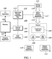
- FIG. 1 an illustrative apparatus 100 that is compatible with many of these teachings will first be presented.
- the enabling apparatus 100 includes a control circuit 101.
- the control circuit 101 therefore comprises structure that includes at least one (and typically many) electrically-conductive paths (such as paths comprised of a conductive metal such as copper or silver) that convey electricity in an ordered manner, which path(s) will also typically include corresponding electrical components (both passive (such as resistors and capacitors) and active (such as any of a variety of semiconductor-based devices) as appropriate) to permit the circuit to effect the control aspect of these teachings.
- Such a control circuit 101 can comprise a fixed-purpose hard-wired hardware platform (including but not limited to an application-specific integrated circuit (ASIC) (which is an integrated circuit that is customized by design for a particular use, rather than intended for general-purpose use), a field-programmable gate array (FPGA), and the like) or can comprise a partially or wholly-programmable hardware platform (including but not limited to microcontrollers, microprocessors, and the like).
- ASIC application-specific integrated circuit
- FPGA field-programmable gate array
- This control circuit 101 is configured (for example, by using corresponding programming as will be well understood by those skilled in the art) to carry out one or more of the steps, actions, and/or functions described herein.
- the control circuit 101 operably couples to a memory 102.
- This memory 102 may be integral to the control circuit 101 or can be physically discrete (in whole or in part) from the control circuit 101 as desired.
- This memory 102 can also be local with respect to the control circuit 101 (where, for example, both share a common circuit board, chassis, power supply, and/or housing) or can be partially or wholly remote with respect to the control circuit 101 (where, for example, the memory 102 is physically located in another facility, metropolitan area, or even country as compared to the control circuit 101).
- this memory 102 can serve, for example, to non-transitorily store the computer instructions that, when executed by the control circuit 101, cause the control circuit 101 to behave as described herein.
- this reference to "non-transitorily” will be understood to refer to a non-ephemeral state for the stored contents (and hence excludes when the stored contents merely constitute signals or waves) rather than volatility of the storage media itself and hence includes both non-volatile memory (such as read-only memory (ROM) as well as volatile memory (such as a dynamic random access memory (DRAM).)
- control circuit 101 also operably couples to a user interface 103.
- This user interface 103 can comprise any of a variety of user-input mechanisms (such as, but not limited to, keyboards and keypads, cursor-control devices, touch-sensitive displays, speech-recognition interfaces, gesture-recognition interfaces, and so forth) and/or user-output mechanisms (such as, but not limited to, visual displays, audio transducers, printers, and so forth) to facilitate receiving information and/or instructions from a user and/or providing information to a user.
- user-input mechanisms such as, but not limited to, keyboards and keypads, cursor-control devices, touch-sensitive displays, speech-recognition interfaces, gesture-recognition interfaces, and so forth
- user-output mechanisms such as, but not limited to, visual displays, audio transducers, printers, and so forth
- control circuit 101 can also operably couple to a network interface (not shown). So configured the control circuit 101 can communicate with other elements (both within the apparatus 100 and external thereto) via the network interface.
- Network interfaces including both wireless and non-wireless platforms, are well understood in the art and require no particular elaboration here.
- a computed tomography apparatus 106 and/or other imaging apparatus 107 can source some or all of any desired patient-related imaging information.
- control circuit 101 is configured to ultimately output an optimized energy-based treatment plan (such as, for example, an optimized energy treatment plan 113).
- This energy-based treatment plan typically comprises specified values for each of a variety of treatment-platform parameters during each of a plurality of sequential exposure fields.
- the energy-based treatment plan is generated through an optimization process, examples of which are provided further herein.
- control circuit 101 can operably couple to an energy-based treatment platform 114 that is configured to deliver therapeutic energy 112 to a corresponding patient 104 having at least one treatment volume 105 and also one or more organs-at-risk (represented in FIG. 1 by a first through an Nth organ-at-risk 108 and 109) in accordance with the optimized energy-based treatment plan 113.
- an energy-based treatment platform 114 includes an energy source such as an energy source 115 of accelerated protons 116.
- this energy source 115 can be selectively moved via a gantry along an arcuate pathway (where the pathway encompasses, at least to some extent, the patient themselves during administration of the treatment).
- the arcuate pathway may comprise a complete or nearly complete circle as desired.
- the control circuit 101 controls the movement of the energy source 115 along that arcuate pathway, and may accordingly control when the energy source 115 starts moving, stops moving, accelerates, de-accelerates, and/or a velocity at which the energy source 115 travels along the arcuate pathway.
- the energy source 115 can comprise a particle accelerator such as a cyclotron or a synchrotron.
- a typical energy-based treatment platform 114 may also include one or more support apparatuses 110 (such as a couch) to support the patient 104 during the treatment session, one or more patient fixation apparatuses 111, and one or more energy-shaping apparatuses (for example, beam-shaping apparatuses 117 such as jaws, multi-leaf collimators, and so forth) to provide selective energy shaping and/or energy modulation as desired.
- support apparatuses 110 such as a couch
- patient fixation apparatuses 111 to support the patient 104 during the treatment session
- energy-shaping apparatuses for example, beam-shaping apparatuses 117 such as jaws, multi-leaf collimators, and so forth
- the patient support apparatus 110 is selectively controllable to move in any direction (i.e., any X, Y, or Z direction) during an energy-based treatment session by the control circuit 101.
- any direction i.e., any X, Y, or Z direction
- this process 200 serves to facilitate generating an optimized energy treatment plan 113 to thereby facilitate treating a particular patient with therapeutic energy using a particular energy treatment platform per that optimized energy treatment plan.
- this process 200 presents (for example, via the aforementioned user interface 103), linear energy transfer information 202 that corresponds to optimizing an energy therapy treatment plan.
- this description will presume this energy therapy treatment plan to be a proton therapy treatment plan. It will be understood, however, that these teachings will accommodate other approaches.
- linear energy transfer information 202 can be provided using alphanumeric content and/or graphic content (where different levels are illustrated, for example, via color or grayscale selections and/or gradients).
- That detected user input may comprise, for example, user-based cursor movement.
- a cursor movement may correspond, for example, to user-based painting of a displayed patient portion (such as all or part of a treatment target and/or one or more organs-at-risk). That painting can serve, for example, to select the painted area/volume for subsequent consideration/treatment per these teachings.
- FIGS. 3 and 4 present a simple illustrative example in these regards.
- the user interface 103 presents a target volume 301 and an organ-at-risk 302.
- the user has moved the screen cursor 303 into a position where, by double clicking a mouse button, the entire target volume 301 is selected/painted as shown in FIG. 4 .
- the detected cursor movement may correspond to modification of one or more spots, thereby resulting in at least one detected spot-based modification.
- spot refers to a specific location within a tumor (or other volume of interest) that is targeted with a precise beam of proton radiation.
- this process 200 accesses a precomputed influence matrix 205 to provide corresponding resultant accessed information.
- the foregoing precomputed influence matrix 205 comprises, at least in part, precomputed linear energy transfer information (which is, to be clear, not necessarily identical to the previously-mentioned linear energy transfer information 202).
- this precomputed influence matrix 205 comprises precomputed linear energy transfer contributions.
- this reference to "precomputed” shall be understood to mean computations that were undertaken and completed prior to the time of need. By one approach, this can mean at a time prior to instigation of this process 200.
- these contributions might comprise a precomputed linear energy transfer contribution for a particular voxel, or precomputed linear energy transfer contributions to each of a plurality of voxels (such as each voxel that corresponds to the user selection referred to above).
- the precomputed influence matrix 205 may comprise each spot's precomputed linear energy transfer contributions for each voxel.
- a voxel represents a value on a regular grid in three-dimensional space.
- medical imaging data such as that which is obtained through computed tomography scans can be used to create a detailed three-dimensional model of a patient's anatomy.
- Each voxel in such a model can also hold information about such things as the density and composition of the underlying tissue at that specific location.
- the contents of the precomputed influence matrix 205 can be computed by storing each spot's linear energy transfer to each voxel. This approach allows these stored contributions to be accessed quickly at a time of need and without need to recalculate such information every time something changes in the developing plan.
- the control circuit 101 can then present modified linear energy transfer information via the user interface 103 as a function, at least in part, of the aforementioned accessed information.
- the user can view, for example, linear energy transfer contributions that were accessed from the precomputed influence matrix 205.
- the foregoing may comprise, for example, having a user select (for example, by painting) a greater (or lesser) level of linear energy transfer (or dose) for a particular patient region, and then reacting automatically by quickly presenting such things as the resulting spot weights, linear energy transfer, and so forth.
- these teachings will accommodate having the user edit spot weights and dosing and then automatically updating and presenting the resultant linear energy transfer results.
- this entire process can be completed in essentially real time (in that, to the user, the foregoing activities can appear to take place instantaneously).
- these teachings will accommodate allowing the user to repeat blocks 201 through 206 any number of times (for example, to test various linear energy transfer levels with various portions of the patient's anatomy) without any undue time consequences, thereby allowing the user the freedom to explore options while making useful, thoughtful observations of the attending potential consequences and/or results of those options.
- these teachings will accommodate completing optimization of the energy therapy treatment plan to provide an optimized energy therapy treatment plan 113.
- these teachings will then optionally accommodate administering therapeutic energy to a corresponding patient 104 as a function of the optimized energy therapy treatment plan 113 using, for example, the corresponding energy treatment platform 114.
Landscapes
- Health & Medical Sciences (AREA)
- Engineering & Computer Science (AREA)
- Biomedical Technology (AREA)
- Pathology (AREA)
- Nuclear Medicine, Radiotherapy & Molecular Imaging (AREA)
- Radiology & Medical Imaging (AREA)
- Life Sciences & Earth Sciences (AREA)
- Animal Behavior & Ethology (AREA)
- General Health & Medical Sciences (AREA)
- Public Health (AREA)
- Veterinary Medicine (AREA)
- Radiation-Therapy Devices (AREA)
Applications Claiming Priority (1)
| Application Number | Priority Date | Filing Date | Title |
|---|---|---|---|
| US18/369,623 US20250090866A1 (en) | 2023-09-18 | 2023-09-18 | Method and apparatus for facilitating optimizing and administering an energy therapy treatment plan |
Publications (1)
| Publication Number | Publication Date |
|---|---|
| EP4523741A1 true EP4523741A1 (de) | 2025-03-19 |
Family
ID=92792271
Family Applications (1)
| Application Number | Title | Priority Date | Filing Date |
|---|---|---|---|
| EP24200108.9A Pending EP4523741A1 (de) | 2023-09-18 | 2024-09-12 | Verfahren und vorrichtung zur optimierung und verabreichung eines energietherapiebehandlungsplans |
Country Status (3)
| Country | Link |
|---|---|
| US (1) | US20250090866A1 (de) |
| EP (1) | EP4523741A1 (de) |
| CN (1) | CN119633265A (de) |
Family Cites Families (2)
| Publication number | Priority date | Publication date | Assignee | Title |
|---|---|---|---|---|
| CN115245636A (zh) * | 2015-12-22 | 2022-10-28 | 皇家飞利浦有限公司 | 至少基于内部器官期望的移动和/或预期的变形的强度调制质子治疗(impt)计划优化 |
| US12377288B2 (en) * | 2020-10-12 | 2025-08-05 | Elekta (Shanghai) Technology Co., Ltd. | Evaluation and presentation of robustness of a treatment plan |
-
2023
- 2023-09-18 US US18/369,623 patent/US20250090866A1/en active Pending
-
2024
- 2024-09-12 EP EP24200108.9A patent/EP4523741A1/de active Pending
- 2024-09-13 CN CN202411282792.6A patent/CN119633265A/zh active Pending
Non-Patent Citations (3)
| Title |
|---|
| LIU CHENBIN ET AL: "Robust Optimization for Intensity Modulated Proton Therapy to Redistribute High Linear Energy Transfer from Nearby Critical Organs to Tumors in Head and Neck Cancer", INTERNATIONAL JOURNAL OF RADIATION: ONCOLOGY BIOLOGY PHYSICS, PERGAMON PRESS, USA, vol. 107, no. 1, 25 January 2020 (2020-01-25), pages 181 - 193, XP086129574, ISSN: 0360-3016, [retrieved on 20200125], DOI: 10.1016/J.IJROBP.2020.01.013 * |
| LIU RUIRUI ET AL: "An Integrated Physical Optimization Framework for Proton Stereotactic Body Radiation Therapy FLASH Treatment Planning Allows Dose, Dose Rate, and Linear Energy Transfer Optimization Using Patient-Specific Ridge Filters", INTERNATIONAL JOURNAL OF RADIATION: ONCOLOGY BIOLOGY PHYSICS, PERGAMON PRESS, USA, vol. 116, no. 4, 21 January 2023 (2023-01-21), pages 949 - 959, XP087343518, ISSN: 0360-3016, [retrieved on 20230201], DOI: 10.1016/J.IJROBP.2023.01.048 * |
| NATHAN HARRISON ET AL: "A novel inverse algorithm to solve IPO-IMPT of proton FLASH therapy with sparse filters", ARXIV.ORG, CORNELL UNIVERSITY LIBRARY, 201 OLIN LIBRARY CORNELL UNIVERSITY ITHACA, NY 14853, 19 April 2023 (2023-04-19), XP091488399 * |
Also Published As
| Publication number | Publication date |
|---|---|
| US20250090866A1 (en) | 2025-03-20 |
| CN119633265A (zh) | 2025-03-18 |
Similar Documents
| Publication | Publication Date | Title |
|---|---|---|
| EP4197593B1 (de) | Verfahren und vorrichtung zur erkennung und reaktion auf strahlenbehandlungsplanpunktgewichtsbearbeitungen | |
| US12138476B2 (en) | Machine learning-based generation of 3D dose distributions for volumes not included in a training corpus | |
| US12064647B2 (en) | Method and apparatus to facilitate generating a leaf sequence for a multi-leaf collimator | |
| US11679273B2 (en) | Method and apparatus to deliver therapeutic radiation to a patient using field geography-based dose optimization | |
| US20230142010A1 (en) | Method and apparatus to facilitate administering therapeutic radiation to a heterogeneous body | |
| EP4474009A1 (de) | Informierte flash-strahlentherapie mit biologischer äquivalenter dosis | |
| EP3932483A1 (de) | Zur planung der strahlungsbehandlung verwendete verfahren und systeme | |
| EP4523741A1 (de) | Verfahren und vorrichtung zur optimierung und verabreichung eines energietherapiebehandlungsplans | |
| US20240189622A1 (en) | Radiation treatment plan optimization as a function of both dosimetric and non-dosimetric parameters | |
| US20220199221A1 (en) | Method and Apparatus to Deliver Therapeutic Energy to a Patient Using Multi-Objective Optimization as a Function of a Patient's Quality of Care | |
| EP4635563A1 (de) | Verfahren und vorrichtung zur optimierung eines strahlenbehandlungsplans | |
| EP4603140A1 (de) | Vorrichtung und verfahren zur berechnung des strahlungsdosisvolumens und strahlungsdosisratenvolumens | |
| US12453866B2 (en) | Detecting anomalous dose volume histogram information | |
| US20250161715A1 (en) | Motion compensation during radiation treatment | |
| EP4631568A1 (de) | Verfahren und vorrichtung zur optimierung eines strahlenbehandlungsplans | |
| US20240001144A1 (en) | Method and apparatus for stereotactic body radiation treatment planning and administration | |
| EP4523738A1 (de) | Verfahren und vorrichtung zur optimierung eines strahlenbehandlungsplans | |
| US20250381418A1 (en) | Radiation treatment plan evaluation method and apparatus | |
| EP4678229A1 (de) | Verfahren und vorrichtung zur optimierung eines strahlenbehandlungsplans |
Legal Events
| Date | Code | Title | Description |
|---|---|---|---|
| PUAI | Public reference made under article 153(3) epc to a published international application that has entered the european phase |
Free format text: ORIGINAL CODE: 0009012 |
|
| STAA | Information on the status of an ep patent application or granted ep patent |
Free format text: STATUS: REQUEST FOR EXAMINATION WAS MADE |
|
| 17P | Request for examination filed |
Effective date: 20240912 |
|
| AK | Designated contracting states |
Kind code of ref document: A1 Designated state(s): AL AT BE BG CH CY CZ DE DK EE ES FI FR GB GR HR HU IE IS IT LI LT LU LV MC ME MK MT NL NO PL PT RO RS SE SI SK SM TR |