EP4521869A1 - Electric switchboard - Google Patents
Electric switchboard Download PDFInfo
- Publication number
- EP4521869A1 EP4521869A1 EP23823442.1A EP23823442A EP4521869A1 EP 4521869 A1 EP4521869 A1 EP 4521869A1 EP 23823442 A EP23823442 A EP 23823442A EP 4521869 A1 EP4521869 A1 EP 4521869A1
- Authority
- EP
- European Patent Office
- Prior art keywords
- region
- casing
- heat
- partition section
- generation component
- Prior art date
- Legal status (The legal status is an assumption and is not a legal conclusion. Google has not performed a legal analysis and makes no representation as to the accuracy of the status listed.)
- Pending
Links
Images
Classifications
-
- H—ELECTRICITY
- H02—GENERATION; CONVERSION OR DISTRIBUTION OF ELECTRIC POWER
- H02M—APPARATUS FOR CONVERSION BETWEEN AC AND AC, BETWEEN AC AND DC, OR BETWEEN DC AND DC, AND FOR USE WITH MAINS OR SIMILAR POWER SUPPLY SYSTEMS; CONVERSION OF DC OR AC INPUT POWER INTO SURGE OUTPUT POWER; CONTROL OR REGULATION THEREOF
- H02M7/00—Conversion of AC power input into DC power output; Conversion of DC power input into AC power output
- H02M7/003—Constructional details, e.g. physical layout, assembly, wiring or busbar connections
-
- H—ELECTRICITY
- H02—GENERATION; CONVERSION OR DISTRIBUTION OF ELECTRIC POWER
- H02B—BOARDS, SUBSTATIONS OR SWITCHING ARRANGEMENTS FOR THE SUPPLY OR DISTRIBUTION OF ELECTRIC POWER
- H02B1/00—Frameworks, boards, panels, desks, casings; Details of substations or switching arrangements
- H02B1/56—Cooling; Ventilation
-
- H—ELECTRICITY
- H05—ELECTRIC TECHNIQUES NOT OTHERWISE PROVIDED FOR
- H05K—PRINTED CIRCUITS; CASINGS OR CONSTRUCTIONAL DETAILS OF ELECTRIC APPARATUS; MANUFACTURE OF ASSEMBLAGES OF ELECTRICAL COMPONENTS
- H05K7/00—Constructional details common to different types of electric apparatus
- H05K7/20—Modifications to facilitate cooling, ventilating, or heating
- H05K7/20009—Modifications to facilitate cooling, ventilating, or heating using a gaseous coolant in electronic enclosures
- H05K7/20136—Forced ventilation, e.g. by fans
- H05K7/20145—Means for directing air flow, e.g. ducts, deflectors, plenum or guides
-
- H—ELECTRICITY
- H05—ELECTRIC TECHNIQUES NOT OTHERWISE PROVIDED FOR
- H05K—PRINTED CIRCUITS; CASINGS OR CONSTRUCTIONAL DETAILS OF ELECTRIC APPARATUS; MANUFACTURE OF ASSEMBLAGES OF ELECTRICAL COMPONENTS
- H05K7/00—Constructional details common to different types of electric apparatus
- H05K7/20—Modifications to facilitate cooling, ventilating, or heating
- H05K7/2089—Modifications to facilitate cooling, ventilating, or heating for power electronics, e.g. for inverters for controlling motor
- H05K7/20909—Forced ventilation, e.g. on heat dissipaters coupled to components
Definitions
- the present disclosure relates to a switchboard.
- PTL 1 discloses a switchboard device including a first ventilation path in which a part of high-heat-generation components is arranged inside and a second ventilation path in which another part of high-heat-generation components is arranged inside while being independent from the first ventilation path.
- the high-heat-generation component is a power conversion component in the switchboard device. Heat generated from the high-heat-generation components inside the first ventilation path and the second ventilation path is removed by driving each of the first fan and the second fan.
- the present disclosure has been made to solve the above problems, and an object of the present disclosure is to provide a switchboard capable of efficiently cooling a high-heat-generation component while preventing an increase in manufacturing cost.
- a switchboard including: a casing; a power converter that is housed in the casing and converts electric power supplied from outside; an intake port capable of introducing air from an outside of the casing into the casing; an exhaust port capable of exhausting the air in the casing to the outside of the casing; a fan capable of causing the air introduced into the casing to flow from the intake port toward the exhaust port; a first partition section that divides a space inside the casing into a first region in which a low-heat-generation component electrically connected to the power converter is arranged and a second region in which the low-heat-generation component is not arranged; and a second partition section that is arranged downstream of the first partition section in a flow direction of the air and divides the second region into an inner region in which a high-heat-generation component electrically connected to the power converter and the low-heat-generation component is arranged and an outer region in which the high-heat-generation component is not arranged,
- the switchboard in the present embodiment is a ship switchboard that converts electric power in a hull of a ship.
- a plurality of switchboards are arranged in an equipment room or the like in the hull.
- a switchboard 100 includes a casing 1, a power converter 2, an intake port 3, an exhaust port 4, a fan 5, a first partition section 6, a low-heat-generation component 7, a second partition section 8, and a high-heat-generation component 9.
- Fig. 1 only one switchboard 100 among the plurality of switchboards 100 is illustrated.
- the casing 1 forms an outer shell of the switchboard 100.
- the casing 1 is formed of, for example, metal.
- the casing 1 is arranged on a floor surface Fs in the equipment room.
- the casing 1 in the present embodiment has a rectangular parallelepiped shape extending in a vertical direction Dv perpendicular to the direction in which the floor surface Fs extends, and defines a space capable of housing a device therein.
- a direction in which the casing 1 extends is referred to as a "vertical direction Dv".
- the upper side in the vertical direction Dv is simply referred to as an "upper side Dvu”
- the lower side opposite thereto is simply referred to as a “lower side Dvd”.
- the casing 1 has an inner surface 10 constituted by a plurality of surfaces.
- a surface arranged on the uppermost side Dvu and oriented toward the lower side Dvd is referred to as a "top surface 11”
- a surface arranged on the lowermost side Dvd and facing the top surface 11 is referred to as a "bottom surface 12”.
- the top surface 11 and the bottom surface 12 are, for example, parallel to each other.
- Four surfaces connecting the top surface 11 and the bottom surface 12 are referred to as "side surfaces 13". In Fig. 1 , only two side surfaces 13 of the four side surfaces 13, which face each other and are parallel to each other, are illustrated due to space limitations.
- the power converter 2 is a device that converts power input from a power source or the like (not illustrated) arranged in the hull outside the casing 1 and outputs the converted power to the outside of the casing 1.
- a plurality of power converters 2 are housed in the casing 1.
- Fig. 1 illustrates an example in which five power converters 2 are housed in the casing 1. These power converters 2 are cooled by a liquid refrigerant or the like supplied from the outside.
- the intake port 3 is a hole through which air outside the casing 1 can be introduced into the casing 1. Therefore, the intake port 3 allows a space outside the casing 1 and a space inside the casing 1 to communicate with each other.
- the intake port 3 is arranged in the casing 1.
- the term "in the casing 1" in the present specification means being formed on the casing 1 to extend over the inner surface 10 and the outer surface of the casing 1, not inside the casing 1.
- a plurality of intake ports 3 are formed on the casing 1 to penetrate from the side surface 13 of the casing 1 toward the outer surface. That is, the plurality of intake ports 3 are arranged in the direction in which the side surface 13 of the casing 1 extends. In Fig. 1 , only one intake port 3 of the plurality of intake ports 3 is illustrated due to space limitations.
- the intake port 3 in the present embodiment penetrates from a portion of the side surface 13 of the casing 1 on the lower side Dvd close to the bottom surface 12 toward the outer surface.
- the exhaust port 4 is a hole through which air in the casing 1 can be exhausted to the outside of the casing 1. Therefore, the exhaust port 4 allows a space outside the casing 1 and a space inside the casing 1 to communicate with each other.
- the exhaust port 4 is arranged in the casing 1.
- the exhaust port 4 in the present embodiment is formed on the casing 1 to penetrate from the top surface 11 of the casing 1 toward the outer surface.
- the fan 5 is a blower capable of causing air introduced into the casing 1 through the intake port 3 to flow from the intake port 3 toward the exhaust port 4.
- the fan 5 is housed in the casing 1.
- the fan 5 in the present embodiment is provided on the top surface 11 of the casing 1 and arranged in the vicinity of the exhaust port 4.
- the first partition section 6 is a member that divides the space inside the casing 1 into a first region R1 and a second region R2.
- the first partition section 6 is formed of, for example, metal.
- the first partition section 6 is housed in the casing 1.
- the first partition section 6 in the present embodiment has a cylindrical shape extending in the vertical direction Dv when housed in the casing 1.
- the first partition section 6 is arranged on the upper side Dvu with respect to the intake port 3.
- the first region R1 created by arranging the first partition section 6 in the casing 1 corresponds to the space inside the first partition section 6.
- the second region R2 created by arranging the first partition section 6 in the casing 1 corresponds to the space on the outer side of the first partition section 6.
- the power converter 2 and the fan 5 are arranged in the second region R2.
- the first partition section 6 has a first inlet opening 61 and a first outlet opening 62.
- the first inlet opening 61 allows a part of the air introduced into the casing 1 through the intake port 3 to flow into the first region R1.
- the first inlet opening 61 is oriented toward the lower side Dvd and faces the bottom surface 12.
- the first inlet opening 61 has a circular shape.
- the first outlet opening 62 allows the air that has flowed through the first region R1 to flow out to the second region R2 on the upper side Dvu with respect to the first partition section 6.
- the first outlet opening 62 is oriented toward the upper side Dvu and faces the top surface 11.
- the first outlet opening 62 has a circular shape.
- a first region R1 between the first inlet opening 61 and the first outlet opening 62 is formed to have a uniform flow path cross-sectional area.
- the term "uniform" mentioned herein refers to being formed substantially uniformly, and slight manufacturing errors and design tolerances are allowed.
- the inner peripheral surface of the first partition section 6 has a cylindrical surface shape. The air in the casing 1 that does not flow into the first region R1 flows toward the upper side Dvu along the outer peripheral surface of the first partition section 6 in the second region R2 around the first partition section 6.
- the low-heat-generation component 7 is a component electrically connected to the power converter 2.
- the low-heat-generation component 7 is housed in the casing 1.
- the low-heat-generation component 7 generates heat when the power converter 2 is driven.
- Examples of the low-heat-generation component 7 in the present embodiment include a terminal block connected to a terminal such as a positive electrode or a negative electrode provided in the power converter 2 by a bus bar or the like.
- the low-heat-generation component 7 is arranged in the first region R1 defined by the first partition section 6. In other words, the low-heat-generation component 7 is housed in the first partition section 6. Therefore, the low-heat-generation component 7 is arranged in the first region R1, and the low-heat-generation component 7 is not arranged in the second region R2.
- a state of electrical connection between the low-heat-generation component 7 and the power converter 2 is conceptually illustrated by a two-dot chain line.
- the second partition section 8 is a member that divides the second region R2 inside the casing 1 into an inner region Ri and an outer region Ro.
- the second partition section 8 is formed of, for example, metal.
- the second partition section 8 is housed in the casing 1.
- the second partition section 8 in the present embodiment has a cylindrical shape formed into a truncated cone shape extending in the vertical direction Dv when housed in the casing 1.
- the second partition section 8 is arranged downstream of the first partition section 6 in the air flow direction in the casing 1. That is, the second partition section 8 in the present embodiment is arranged on the upper side Dvu with respect to the first partition section 6.
- the inner region Ri created by arranging the second partition section 8 in the casing 1 corresponds to the space inside the second partition section 8.
- the outer region Ro created by arranging the second partition section 8 in the casing 1 corresponds to the space on the outer side of the second partition section 8.
- the power converter 2 and the fan 5 are arranged in the outer region Ro of the second region R2.
- the second partition section 8 has a second inlet opening 81 and a second outlet opening 82.
- the second inlet opening 81 allows the air flowing out from the first region R1 through the first outlet opening 62 and a part of the air flowing toward the upper side Dvu through the second region R2 around the first partition section 6 to flow into the inner region Ri.
- the second inlet opening 81 is oriented toward the lower side Dvd and faces the bottom surface 12 and the first outlet opening 62.
- the second inlet opening 81 has a circular shape.
- the second outlet opening 82 allows the air flowing that has flowed through the inner region Ri to flow out to the outer region Ro on the upper side Dvu with respect to the second partition section 8.
- the second outlet opening 82 is oriented toward the upper side Dvu and faces the top surface 11.
- the second outlet opening 82 has a circular shape.
- the inner region Ri between the second inlet opening 81 and the second outlet opening 82 is formed so that the flow path cross-sectional area increases from the second inlet opening 81 toward the second outlet opening 82.
- the second partition section 8 is formed so that the flow path cross-sectional area of the inner region Ri gradually increases from the second inlet opening 81 to the second outlet opening 82.
- the inner peripheral surface of the second partition section 8 has a funnel shape. The air in the casing 1 that does not flow into the inner region Ri flows toward the upper side Dvu along the outer peripheral surface of the second partition section 8 in the outer region Ro around the second partition section 8.
- the opening area of the second inlet opening 81 is larger than the opening area of the first outlet opening 62. Therefore, an inner diameter L2 of the second inlet opening 81 is larger than an inner diameter L1 of the first inlet opening 61. An inner diameter L3 of the second outlet opening 82 is larger than the inner diameter L2 of the second inlet opening 81.
- the high-heat-generation component 9 is a component electrically connected to the power converter 2 and the low-heat-generation component 7.
- the high-heat-generation component 9 is housed in the casing 1.
- the high-heat-generation component 9 generates more heat than the low-heat-generation component 7 when the power converter 2 is driven.
- Examples of the high-heat-generation component 9 in the present embodiment include circuit elements such as a fuse for the power converter 2 arranged in a current path connecting the power converter 2 and the low-heat-generation component 7, and a fuse (bus tie fuse) arranged in a current path extending from the low-heat-generation component 7 toward another switchboard 100.
- the high-heat-generation component 9 is arranged in the inner region Ri defined by the second partition section 8.
- the high-heat-generation component 9 is housed in the second partition section 8.
- the high-heat-generation component 9 is arranged in the vicinity of the second inlet opening 81 in the inner region Ri.
- the "vicinity of the second inlet opening 81" means, for example, an inner region Ri on a lower half side when the second partition section 8 is divided into two in the vertical direction Dv.
- the high-heat-generation component 9 is arranged in the inner region Ri, and the high-heat-generation component 9 is not arranged in the outer region Ro.
- a state of electrical connection between the high-heat-generation component 9, and the power converter 2 and the low-heat-generation component 7 is conceptually illustrated by a two-dot chain line.
- the air flowing out of the first region R1 through the first outlet opening 62 and a part of the air flowing toward the upper side Dvu through the outer region Ro on the lower side Dvd with respect to the second partition section 8 are guided to the inner region Ri through the second inlet opening 81. That is, air having a temperature lower than the temperature of the air flowing through the first region R1 can be taken into the inner region Ri.
- the high-heat-generation component 9 is efficiently cooled.
- the above operations can be achieved by a simple configuration in which the first partition section 6 and the second partition section 8 are arranged in the casing 1. Therefore, it is possible to efficiently cool the high-heat-generation component 9 while preventing an increase in manufacturing cost of the switchboard 100.
- the high-heat-generation component 9 is arranged on the upper side Dvu with respect to the low-heat-generation component 7. Accordingly, since the heat generated from the high-heat-generation component 9 and the air that has exchanged heat with the high-heat-generation component 9 move to the upper side Dvu with respect to the high-heat-generation component 9, the heat and the air do not reach the low-heat-generation component 7. Therefore, for example, the low-heat-generation component 7 is not affected by heat from the high-heat-generation component 9 as compared with a case where the low-heat-generation component 7 is arranged on the upper side Dvu with respect to the high-heat-generation component 9. As a result, the low-heat-generation component 7 can be efficiently cooled.
- the space in which the switchboard 100 can be installed may be limited.
- the low-heat-generation component 7 and the high-heat-generation component 9 are air-cooled while being arranged in the vertical direction Dv, for example, it is possible to reduce an occupied space of the switchboard 100 in the direction parallel to the floor surface Fs as compared with a case where these components are arranged in the casing 1 in a direction parallel to the floor surface Fs.
- the opening area of the second inlet opening 81 facing the first outlet opening 62 is larger than the opening area of the first outlet opening 62, the air flowing out from the first region R1 can be smoothly guided to the inner region Ri. Therefore, since the momentum of the air whose flow velocity has increased in the first region R1 can be efficiently used, the flow velocity of the air guided to the inner region Ri increases. As a result, the high-heat-generation component 9 can be cooled more efficiently.
- the second inlet opening 81 since the second inlet opening 81 has a circular shape, the air flowing through the outer region Ro around the first partition section 6 can be smoothly guided to the inner region Ri.
- the second outlet opening 82 since the second outlet opening 82 has a circular shape, the air can smoothly flow out from the inner region Ri to the upper side Dvu as compared with a case where the second outlet opening 82 has another shape. As a result, the high-heat-generation component 9 can be cooled more efficiently.
- the first partition section 6 may have, for example, a plate shape, and may divide the space inside the casing 1 together with the side surface 13 on the inner surface 10 of the casing 1 into a first region R1 in which the low-heat-generation component 7 is arranged and a second region R2 in which the low-heat-generation component 7 is not arranged. Therefore, the first inlet opening 61 and the first outlet opening 62 are not limited to a circular shape, and may have a polygonal shape such as a rectangular shape.
- the second partition section 8 has a cylindrical shape formed into a truncated cone shape extending in the vertical direction Dv
- the present invention is not limited to this configuration.
- the second partition section 8 may have, for example, a plate shape, and may divide the second region R2 together with the side surface 13 of the inner surface 10 of the casing 1 into an inner region Ri in which the high-heat-generation component 9 is arranged and an outer region Ro in which the high-heat-generation component 9 is not arranged. Therefore, the second inlet opening 81 and the second outlet opening 82 are not limited to a circular shape, and may have a polygonal shape such as a rectangular shape.
- first partition section 6 and the second partition section 8 are formed of metal
- present invention is not limited to this configuration.
- the first partition section 6 and the second partition section 8 may be formed of, for example, a synthetic resin or the like.
- the intake port 3 is formed on the casing 1 to penetrate from the side surface 13 of the inner surface 10 of the casing 1 toward the outer surface
- the present invention is not limited to this configuration.
- the intake port 3 may be formed on the casing 1 to penetrate from the bottom surface 12 of the inner surface 10 of the casing 1 toward the floor surface Fs.
- a gap that allows the air to flow need only be formed between the casing 1 and the floor surface Fs while the casing 1 is supported by, for example, a stand or the like (not illustrated) arranged on the floor surface Fs.
- the case where five power converters 2 are housed in the casing 1 has been described, but the number of power converters 2 is not limited to five. Four or less or six or more power converters 2 may be housed in the casing 1.
- the present invention is not limited to the liquid refrigerant.
- the power converter 2 may be configured to be cooled by air cooling or the like, for example. Specifically, the power converter 2 may be cooled by the air introduced into the casing 1 from the intake port 3.
- the present invention is not limited to this configuration.
- the opening area of the second inlet opening 81 may be the same as the opening area of the first outlet opening 62. Therefore, the inner diameter L2 of the second inlet opening 81 may be the same as the inner diameter L1 of the first inlet opening 61.
- the opening area of the second inlet opening 81 need only be equal to or larger than the opening area of the first outlet opening 62. This also makes it possible to achieve the above-described operations and effects.
- the inner diameter L3 of the second outlet opening 82 may be the same as the inner diameter L2 of the second inlet opening 81.
- the switchboard 100 described in the above embodiment is not limited to a ship switchboard that converts electric power in a hull of a ship, but may be a switchboard used in a facility such as a power plant where electric power conversion is required.
- the switchboard described in the embodiment is understood as follows, for example.
- the air pressure in the inner region Ri is lower than the air pressure in the outer region Ro
- the flow velocity of the air in contact with the high-heat-generation component 9 arranged in the inner region Ri is higher than the flow velocity of the air flowing through the outer region Ro.
- the air flowing out from the first region R1 and the air in the outer region Ro having a temperature lower than a temperature of the air flowing through the first region R1 are guided to the inner region Ri through the second inlet opening 81. Therefore, the high-heat-generation component 9 can be efficiently cooled.
- the above operations can be achieved by a simple configuration in which the first partition section 6 and the second partition section 8 are arranged in the casing 1 without additionally providing the fan 5 or the like.
- the switchboard 100 according to a second aspect is the switchboard 100 according to the first aspect, in which an opening area of the second inlet opening 81 may be equal to or larger than an opening area of the first outlet opening 62.
- the air flowing out from the first region R1 can be smoothly guided to the inner region Ri. Therefore, the momentum of the air whose flow velocity has increased in the first region R1 can be efficiently used, and as a result, the flow velocity of the air guided to the inner region Ri can be increased.
- the switchboard 100 according to a third aspect is the switchboard 100 according to the first aspect or the second aspect, in which the second inlet opening 81 and the second outlet opening 82 may have a circular shape.
- the air flowing through the outer region Ro around the first partition section 6 can be smoothly guided to the inner region Ri, and the air from the inner region Ri can flow out smoothly to the upper side Dvu.
Landscapes
- Engineering & Computer Science (AREA)
- Microelectronics & Electronic Packaging (AREA)
- Physics & Mathematics (AREA)
- Thermal Sciences (AREA)
- Power Engineering (AREA)
- Cooling Or The Like Of Electrical Apparatus (AREA)
- Inverter Devices (AREA)
- Patch Boards (AREA)
Abstract
Description
- The present disclosure relates to a switchboard.
- Priority is claimed on
Japanese Patent Application No. 2022-96075, filed June 14, 2022 - For example, PTL 1 discloses a switchboard device including a first ventilation path in which a part of high-heat-generation components is arranged inside and a second ventilation path in which another part of high-heat-generation components is arranged inside while being independent from the first ventilation path. The high-heat-generation component is a power conversion component in the switchboard device. Heat generated from the high-heat-generation components inside the first ventilation path and the second ventilation path is removed by driving each of the first fan and the second fan.
- [PTL 1]
Japanese Unexamined Patent Application Publication No. 2015-65747 - In recent years, in the field of switchboard devices, there has been an increasing trend toward higher voltages, larger currents, higher frequencies, and faster switching in order to improve added values. Accordingly, there is a demand for a technique for efficiently cooling a high-heat-generation component such as a fuse used in a switchboard device. In the technique described in PTL 1, since a plurality of ventilation paths independent of each other are formed, the structure for cooling the high-heat-generation component is complicated. In addition, it is necessary to provide a fan for each ventilation path. As a result, the manufacturing cost of the switchboard device may increase.
- The present disclosure has been made to solve the above problems, and an object of the present disclosure is to provide a switchboard capable of efficiently cooling a high-heat-generation component while preventing an increase in manufacturing cost. Solution to Problem
- In order to solve the above problem, a switchboard according to the present disclosure including: a casing; a power converter that is housed in the casing and converts electric power supplied from outside; an intake port capable of introducing air from an outside of the casing into the casing; an exhaust port capable of exhausting the air in the casing to the outside of the casing; a fan capable of causing the air introduced into the casing to flow from the intake port toward the exhaust port; a first partition section that divides a space inside the casing into a first region in which a low-heat-generation component electrically connected to the power converter is arranged and a second region in which the low-heat-generation component is not arranged; and a second partition section that is arranged downstream of the first partition section in a flow direction of the air and divides the second region into an inner region in which a high-heat-generation component electrically connected to the power converter and the low-heat-generation component is arranged and an outer region in which the high-heat-generation component is not arranged, in which the first partition section includes: a first inlet opening that allows the air introduced into the casing through the intake port to flow into the first region; and a first outlet opening that allows the air that has flowed through the first region to flow out to the second region, the second partition section includes: a second inlet opening that faces the first outlet opening in the flow direction of the air while being spaced apart from the first outlet opening; and a second outlet opening that allows the air that has flowed through the inner region to flow out to the outer region, and the second partition section is formed so that a flow path cross-sectional area of the inner region increases from the second inlet opening toward the second outlet opening.
- According to the present disclosure, it is possible to provide a switchboard capable of efficiently cooling a high-heat-generation component while preventing an increase in manufacturing cost.
-
-
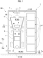
Fig. 1 is a cross-sectional view of a switchboard illustrating a configuration of the switchboard according to an embodiment of the present disclosure. -
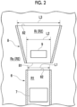
Fig. 2 is an enlarged view of a main part inFig. 1 . - Hereinafter, an embodiment of a switchboard according to the present disclosure will be described with reference to the accompanying drawings.
- The switchboard in the present embodiment is a ship switchboard that converts electric power in a hull of a ship. A plurality of switchboards are arranged in an equipment room or the like in the hull. As illustrated in
Fig. 1 , aswitchboard 100 includes a casing 1, apower converter 2, anintake port 3, an exhaust port 4, afan 5, afirst partition section 6, a low-heat-generation component 7, asecond partition section 8, and a high-heat-generation component 9. InFig. 1 , only oneswitchboard 100 among the plurality ofswitchboards 100 is illustrated. - The casing 1 forms an outer shell of the
switchboard 100. The casing 1 is formed of, for example, metal. The casing 1 is arranged on a floor surface Fs in the equipment room. The casing 1 in the present embodiment has a rectangular parallelepiped shape extending in a vertical direction Dv perpendicular to the direction in which the floor surface Fs extends, and defines a space capable of housing a device therein. - Hereinafter, for convenience of description, a direction in which the casing 1 extends is referred to as a "vertical direction Dv". At this time, the upper side in the vertical direction Dv is simply referred to as an "upper side Dvu", and the lower side opposite thereto is simply referred to as a "lower side Dvd". The casing 1 has an
inner surface 10 constituted by a plurality of surfaces. - Among the plurality of surfaces constituting the
inner surface 10, a surface arranged on the uppermost side Dvu and oriented toward the lower side Dvd is referred to as a "top surface 11", and a surface arranged on the lowermost side Dvd and facing thetop surface 11 is referred to as a "bottom surface 12". Thetop surface 11 and thebottom surface 12 are, for example, parallel to each other. Four surfaces connecting thetop surface 11 and thebottom surface 12 are referred to as "side surfaces 13". InFig. 1 , only twoside surfaces 13 of the fourside surfaces 13, which face each other and are parallel to each other, are illustrated due to space limitations. - The
power converter 2 is a device that converts power input from a power source or the like (not illustrated) arranged in the hull outside the casing 1 and outputs the converted power to the outside of the casing 1. A plurality ofpower converters 2 are housed in the casing 1.Fig. 1 illustrates an example in which fivepower converters 2 are housed in the casing 1. Thesepower converters 2 are cooled by a liquid refrigerant or the like supplied from the outside. - The
intake port 3 is a hole through which air outside the casing 1 can be introduced into the casing 1. Therefore, theintake port 3 allows a space outside the casing 1 and a space inside the casing 1 to communicate with each other. Theintake port 3 is arranged in the casing 1. The term "in the casing 1" in the present specification means being formed on the casing 1 to extend over theinner surface 10 and the outer surface of the casing 1, not inside the casing 1. - A plurality of
intake ports 3 are formed on the casing 1 to penetrate from theside surface 13 of the casing 1 toward the outer surface. That is, the plurality ofintake ports 3 are arranged in the direction in which theside surface 13 of the casing 1 extends. InFig. 1 , only oneintake port 3 of the plurality ofintake ports 3 is illustrated due to space limitations. Theintake port 3 in the present embodiment penetrates from a portion of theside surface 13 of the casing 1 on the lower side Dvd close to thebottom surface 12 toward the outer surface. - The exhaust port 4 is a hole through which air in the casing 1 can be exhausted to the outside of the casing 1. Therefore, the exhaust port 4 allows a space outside the casing 1 and a space inside the casing 1 to communicate with each other. The exhaust port 4 is arranged in the casing 1. The exhaust port 4 in the present embodiment is formed on the casing 1 to penetrate from the
top surface 11 of the casing 1 toward the outer surface. - The
fan 5 is a blower capable of causing air introduced into the casing 1 through theintake port 3 to flow from theintake port 3 toward the exhaust port 4. Thefan 5 is housed in the casing 1. Thefan 5 in the present embodiment is provided on thetop surface 11 of the casing 1 and arranged in the vicinity of the exhaust port 4. - When the
fan 5 is driven, air is introduced into the casing 1 from the outside through theintake port 3. The air introduced into the casing 1 flows toward the upper side Dvu and is exhausted to the outside of the casing 1 through the exhaust port 4. - The
first partition section 6 is a member that divides the space inside the casing 1 into a first region R1 and a second region R2. Thefirst partition section 6 is formed of, for example, metal. Thefirst partition section 6 is housed in the casing 1. Thefirst partition section 6 in the present embodiment has a cylindrical shape extending in the vertical direction Dv when housed in the casing 1. Thefirst partition section 6 is arranged on the upper side Dvu with respect to theintake port 3. - The first region R1 created by arranging the
first partition section 6 in the casing 1 corresponds to the space inside thefirst partition section 6. The second region R2 created by arranging thefirst partition section 6 in the casing 1 corresponds to the space on the outer side of thefirst partition section 6. Thepower converter 2 and thefan 5 are arranged in the second region R2. Here, thefirst partition section 6 has a first inlet opening 61 and afirst outlet opening 62. - The first inlet opening 61 allows a part of the air introduced into the casing 1 through the
intake port 3 to flow into the first region R1. The first inlet opening 61 is oriented toward the lower side Dvd and faces thebottom surface 12. The first inlet opening 61 has a circular shape. The first outlet opening 62 allows the air that has flowed through the first region R1 to flow out to the second region R2 on the upper side Dvu with respect to thefirst partition section 6. The first outlet opening 62 is oriented toward the upper side Dvu and faces thetop surface 11. The first outlet opening 62 has a circular shape. - A first region R1 between the first inlet opening 61 and the first outlet opening 62 is formed to have a uniform flow path cross-sectional area. The term "uniform" mentioned herein refers to being formed substantially uniformly, and slight manufacturing errors and design tolerances are allowed. The inner peripheral surface of the
first partition section 6 has a cylindrical surface shape. The air in the casing 1 that does not flow into the first region R1 flows toward the upper side Dvu along the outer peripheral surface of thefirst partition section 6 in the second region R2 around thefirst partition section 6. - The low-heat-
generation component 7 is a component electrically connected to thepower converter 2. The low-heat-generation component 7 is housed in the casing 1. The low-heat-generation component 7 generates heat when thepower converter 2 is driven. Examples of the low-heat-generation component 7 in the present embodiment include a terminal block connected to a terminal such as a positive electrode or a negative electrode provided in thepower converter 2 by a bus bar or the like. - The low-heat-
generation component 7 is arranged in the first region R1 defined by thefirst partition section 6. In other words, the low-heat-generation component 7 is housed in thefirst partition section 6. Therefore, the low-heat-generation component 7 is arranged in the first region R1, and the low-heat-generation component 7 is not arranged in the second region R2. InFig. 1 , a state of electrical connection between the low-heat-generation component 7 and thepower converter 2 is conceptually illustrated by a two-dot chain line. - The
second partition section 8 is a member that divides the second region R2 inside the casing 1 into an inner region Ri and an outer region Ro. Thesecond partition section 8 is formed of, for example, metal. Thesecond partition section 8 is housed in the casing 1. Thesecond partition section 8 in the present embodiment has a cylindrical shape formed into a truncated cone shape extending in the vertical direction Dv when housed in the casing 1. - The
second partition section 8 is arranged downstream of thefirst partition section 6 in the air flow direction in the casing 1. That is, thesecond partition section 8 in the present embodiment is arranged on the upper side Dvu with respect to thefirst partition section 6. - The inner region Ri created by arranging the
second partition section 8 in the casing 1 corresponds to the space inside thesecond partition section 8. The outer region Ro created by arranging thesecond partition section 8 in the casing 1 corresponds to the space on the outer side of thesecond partition section 8. Thepower converter 2 and thefan 5 are arranged in the outer region Ro of the second region R2. Here, thesecond partition section 8 has a second inlet opening 81 and a second outlet opening 82. - The second inlet opening 81 allows the air flowing out from the first region R1 through the
first outlet opening 62 and a part of the air flowing toward the upper side Dvu through the second region R2 around thefirst partition section 6 to flow into the inner region Ri. The second inlet opening 81 is oriented toward the lower side Dvd and faces thebottom surface 12 and thefirst outlet opening 62. The second inlet opening 81 has a circular shape. The second outlet opening 82 allows the air flowing that has flowed through the inner region Ri to flow out to the outer region Ro on the upper side Dvu with respect to thesecond partition section 8. The second outlet opening 82 is oriented toward the upper side Dvu and faces thetop surface 11. The second outlet opening 82 has a circular shape. - The inner region Ri between the second inlet opening 81 and the second outlet opening 82 is formed so that the flow path cross-sectional area increases from the second inlet opening 81 toward the second outlet opening 82. In other words, the
second partition section 8 is formed so that the flow path cross-sectional area of the inner region Ri gradually increases from the second inlet opening 81 to the second outlet opening 82. The inner peripheral surface of thesecond partition section 8 has a funnel shape. The air in the casing 1 that does not flow into the inner region Ri flows toward the upper side Dvu along the outer peripheral surface of thesecond partition section 8 in the outer region Ro around thesecond partition section 8. - As illustrated in
Fig. 2 , the opening area of the second inlet opening 81 is larger than the opening area of thefirst outlet opening 62. Therefore, an inner diameter L2 of the second inlet opening 81 is larger than an inner diameter L1 of thefirst inlet opening 61. An inner diameter L3 of the second outlet opening 82 is larger than the inner diameter L2 of the second inlet opening 81. - The high-heat-generation component 9 is a component electrically connected to the
power converter 2 and the low-heat-generation component 7. The high-heat-generation component 9 is housed in the casing 1. The high-heat-generation component 9 generates more heat than the low-heat-generation component 7 when thepower converter 2 is driven. Examples of the high-heat-generation component 9 in the present embodiment include circuit elements such as a fuse for thepower converter 2 arranged in a current path connecting thepower converter 2 and the low-heat-generation component 7, and a fuse (bus tie fuse) arranged in a current path extending from the low-heat-generation component 7 toward anotherswitchboard 100. - The high-heat-generation component 9 is arranged in the inner region Ri defined by the
second partition section 8. In other words, the high-heat-generation component 9 is housed in thesecond partition section 8. Specifically, the high-heat-generation component 9 is arranged in the vicinity of the second inlet opening 81 in the inner region Ri. Here, the "vicinity of the second inlet opening 81" means, for example, an inner region Ri on a lower half side when thesecond partition section 8 is divided into two in the vertical direction Dv. - Therefore, the high-heat-generation component 9 is arranged in the inner region Ri, and the high-heat-generation component 9 is not arranged in the outer region Ro. In
Fig. 1 , a state of electrical connection between the high-heat-generation component 9, and thepower converter 2 and the low-heat-generation component 7 is conceptually illustrated by a two-dot chain line. - In the above configuration, since the flow path cross-sectional area of the inner region Ri increases toward the upper side Dvu, when air flows through the inner region Ri as the
fan 5 is driven, the air is decompressed and expanded in the inner region Ri. As a result, since the air pressure in the inner region Ri is lower than the air pressure in the outer region Ro, the flow velocity of the air in contact with the high-heat-generation component 9 arranged in the inner region Ri is higher than the flow velocity of the air flowing through the outer region Ro. In addition, the air flowing out of the first region R1 through thefirst outlet opening 62 and a part of the air flowing toward the upper side Dvu through the outer region Ro on the lower side Dvd with respect to thesecond partition section 8 are guided to the inner region Ri through the second inlet opening 81. That is, air having a temperature lower than the temperature of the air flowing through the first region R1 can be taken into the inner region Ri. By these operations, the high-heat-generation component 9 is efficiently cooled. Further, it is not necessary to additionally provide thefan 5 or the like in order to increase the flow velocity of the air in contact with the high-heat-generation component 9. Further, the above operations can be achieved by a simple configuration in which thefirst partition section 6 and thesecond partition section 8 are arranged in the casing 1. Therefore, it is possible to efficiently cool the high-heat-generation component 9 while preventing an increase in manufacturing cost of theswitchboard 100. - According to the above configuration, the high-heat-generation component 9 is arranged on the upper side Dvu with respect to the low-heat-
generation component 7. Accordingly, since the heat generated from the high-heat-generation component 9 and the air that has exchanged heat with the high-heat-generation component 9 move to the upper side Dvu with respect to the high-heat-generation component 9, the heat and the air do not reach the low-heat-generation component 7. Therefore, for example, the low-heat-generation component 7 is not affected by heat from the high-heat-generation component 9 as compared with a case where the low-heat-generation component 7 is arranged on the upper side Dvu with respect to the high-heat-generation component 9. As a result, the low-heat-generation component 7 can be efficiently cooled. - Further, in an equipment room or the like in the hull, the space in which the
switchboard 100 can be installed may be limited. According to the above configuration, since the low-heat-generation component 7 and the high-heat-generation component 9 are air-cooled while being arranged in the vertical direction Dv, for example, it is possible to reduce an occupied space of theswitchboard 100 in the direction parallel to the floor surface Fs as compared with a case where these components are arranged in the casing 1 in a direction parallel to the floor surface Fs. - Further, according to the above configuration, since the opening area of the second inlet opening 81 facing the first outlet opening 62 is larger than the opening area of the first outlet opening 62, the air flowing out from the first region R1 can be smoothly guided to the inner region Ri. Therefore, since the momentum of the air whose flow velocity has increased in the first region R1 can be efficiently used, the flow velocity of the air guided to the inner region Ri increases. As a result, the high-heat-generation component 9 can be cooled more efficiently.
- According to the above configuration, since the second inlet opening 81 has a circular shape, the air flowing through the outer region Ro around the
first partition section 6 can be smoothly guided to the inner region Ri. In addition, since the second outlet opening 82 has a circular shape, the air can smoothly flow out from the inner region Ri to the upper side Dvu as compared with a case where the second outlet opening 82 has another shape. As a result, the high-heat-generation component 9 can be cooled more efficiently. - The embodiment of the present disclosure has been described in detail above with reference to the drawings. However, a specific configuration is not limited to the configuration of the embodiment, and additions, omissions, and substitutions of components and other modifications can be made without departing from the scope of the present disclosure.
- In the above embodiment, the configuration in which the
first partition section 6 has a cylindrical shape extending in the vertical direction Dv has been described, but the present invention is not limited to this configuration. Although detailed illustration is omitted, thefirst partition section 6 may have, for example, a plate shape, and may divide the space inside the casing 1 together with theside surface 13 on theinner surface 10 of the casing 1 into a first region R1 in which the low-heat-generation component 7 is arranged and a second region R2 in which the low-heat-generation component 7 is not arranged. Therefore, the first inlet opening 61 and the first outlet opening 62 are not limited to a circular shape, and may have a polygonal shape such as a rectangular shape. - In the above embodiment, the configuration in which the
second partition section 8 has a cylindrical shape formed into a truncated cone shape extending in the vertical direction Dv has been described, but the present invention is not limited to this configuration. Although detailed illustration is omitted, thesecond partition section 8 may have, for example, a plate shape, and may divide the second region R2 together with theside surface 13 of theinner surface 10 of the casing 1 into an inner region Ri in which the high-heat-generation component 9 is arranged and an outer region Ro in which the high-heat-generation component 9 is not arranged. Therefore, the second inlet opening 81 and the second outlet opening 82 are not limited to a circular shape, and may have a polygonal shape such as a rectangular shape. - In the above embodiment, the configuration in which the
first partition section 6 and thesecond partition section 8 are formed of metal has been described, but the present invention is not limited to this configuration. Thefirst partition section 6 and thesecond partition section 8 may be formed of, for example, a synthetic resin or the like. - In the above embodiment, the configuration in which the
intake port 3 is formed on the casing 1 to penetrate from theside surface 13 of theinner surface 10 of the casing 1 toward the outer surface has been described, but the present invention is not limited to this configuration. For example, theintake port 3 may be formed on the casing 1 to penetrate from thebottom surface 12 of theinner surface 10 of the casing 1 toward the floor surface Fs. In this case, a gap that allows the air to flow need only be formed between the casing 1 and the floor surface Fs while the casing 1 is supported by, for example, a stand or the like (not illustrated) arranged on the floor surface Fs. - In the above embodiment, the case where five
power converters 2 are housed in the casing 1 has been described, but the number ofpower converters 2 is not limited to five. Four or less or six ormore power converters 2 may be housed in the casing 1. - Further, in the above embodiment, the configuration in which the
power converter 2 is cooled by the liquid refrigerant or the like supplied from the outside has been described, but the present invention is not limited to the liquid refrigerant. Thepower converter 2 may be configured to be cooled by air cooling or the like, for example. Specifically, thepower converter 2 may be cooled by the air introduced into the casing 1 from theintake port 3. - In the above embodiment, the configuration in which the opening area of the second inlet opening 81 is larger than the opening area of the first outlet opening 62 has been described, but the present invention is not limited to this configuration. The opening area of the second inlet opening 81 may be the same as the opening area of the
first outlet opening 62. Therefore, the inner diameter L2 of the second inlet opening 81 may be the same as the inner diameter L1 of thefirst inlet opening 61. - Therefore, the opening area of the second inlet opening 81 need only be equal to or larger than the opening area of the
first outlet opening 62. This also makes it possible to achieve the above-described operations and effects. The inner diameter L3 of the second outlet opening 82 may be the same as the inner diameter L2 of the second inlet opening 81. - The
switchboard 100 described in the above embodiment is not limited to a ship switchboard that converts electric power in a hull of a ship, but may be a switchboard used in a facility such as a power plant where electric power conversion is required. - The switchboard described in the embodiment is understood as follows, for example.
-
- (1) A switchboard 100 comprising a first aspect including: a casing 1; a power converter 2 that is housed in the casing 1 and converts electric power supplied from outside; an intake port 3 capable of introducing air from an outside of the casing 1 into the casing 1; an exhaust port 4 capable of exhausting the air in the casing 1 to the outside of the casing 1; a fan 5 capable of causing the air introduced into the casing 1 to flow from the intake port 3 toward the exhaust port 4; a first partition section 6 that divides a space inside the casing 1 into a first region R1 in which a low-heat-generation component 7 electrically connected to the power converter 2 is arranged and a second region R2 in which the low-heat-generation component 7 is not arranged; and a second partition section 8 that is arranged downstream of the first partition section 6 in a flow direction of the air and divides the second region R2 into an inner region Ri in which a high-heat-generation component 9 electrically connected to the power converter 2 and the low-heat-generation component 7 is arranged and an outer region Ro in which the high-heat-generation component 9 is not arranged, in which the first partition section 6 includes: a first inlet opening 61 that allows the air introduced into the casing 1 through the intake port 3 to flow into the first region R1; and a first outlet opening 62 that allows the air that has flowed through the first region R1 to flow out to the second region R2, the second partition section 8 includes: a second inlet opening 81 that faces the first outlet opening 62 in the flow direction of the air while being spaced apart from the first outlet opening 62; and a second outlet opening 82 that allows the air that has flowed through the inner region Ri to flow out to the outer region Ro, and the second partition section 8 is formed so that a flow path cross-sectional area of the inner region Ri increases from the second inlet opening 81 toward the second outlet opening 82.
- As a result, since the air pressure in the inner region Ri is lower than the air pressure in the outer region Ro, the flow velocity of the air in contact with the high-heat-generation component 9 arranged in the inner region Ri is higher than the flow velocity of the air flowing through the outer region Ro. Further, the air flowing out from the first region R1 and the air in the outer region Ro having a temperature lower than a temperature of the air flowing through the first region R1 are guided to the inner region Ri through the second inlet opening 81. Therefore, the high-heat-generation component 9 can be efficiently cooled. In addition, the above operations can be achieved by a simple configuration in which the
first partition section 6 and thesecond partition section 8 are arranged in the casing 1 without additionally providing thefan 5 or the like. - (2) The
switchboard 100 according to a second aspect is theswitchboard 100 according to the first aspect, in which an opening area of the second inlet opening 81 may be equal to or larger than an opening area of thefirst outlet opening 62. - Accordingly, the air flowing out from the first region R1 can be smoothly guided to the inner region Ri. Therefore, the momentum of the air whose flow velocity has increased in the first region R1 can be efficiently used, and as a result, the flow velocity of the air guided to the inner region Ri can be increased.
- (3) The
switchboard 100 according to a third aspect is theswitchboard 100 according to the first aspect or the second aspect, in which the second inlet opening 81 and the second outlet opening 82 may have a circular shape. - Accordingly, the air flowing through the outer region Ro around the
first partition section 6 can be smoothly guided to the inner region Ri, and the air from the inner region Ri can flow out smoothly to the upper side Dvu. - According to the present disclosure, it is possible to provide a switchboard capable of efficiently cooling a high-heat-generation component while preventing an increase in manufacturing cost.
-
- 1: casing
- 2: power converter
- 3: intake port
- 4: exhaust port
- 5: fan
- 6: first partition section
- 7: low-heat-generation component
- 8: second partition section
- 9: high-heat-generation component
- 10: inner surface
- 11: top surface
- 12: bottom surface
- 13: side surface
- 61: first inlet opening
- 62: first outlet opening
- 81: second inlet opening
- 82: second outlet opening
- 100: switchboard
- Dv: vertical direction
- Dvd: lower side
- Dvu: upper side
- Fs: floor surface
- L1: inner diameter of first outlet opening
- L2: inner diameter of second inlet opening
- L3: inner diameter of second outlet opening
- R1: first region
- R2: second region
- Ri: inner region
- Ro: outer region
Claims (3)
- A switchboard comprising:a casing;a power converter that is housed in the casing and converts electric power supplied from outside;an intake port capable of introducing air from an outside of the casing into the casing;an exhaust port capable of exhausting the air in the casing to the outside of the casing;a fan capable of causing the air introduced into the casing to flow from the intake port toward the exhaust port;a first partition section that divides a space inside the casing into a first region in which a low-heat-generation component electrically connected to the power converter is arranged and a second region in which the low-heat-generation component is not arranged; anda second partition section that is arranged downstream of the first partition section in a flow direction of the air and divides the second region into an inner region in which a high-heat-generation component electrically connected to the power converter and the low-heat-generation component is arranged and an outer region in which the high-heat-generation component is not arranged,wherein the first partition section includes:a first inlet opening that allows the air introduced into the casing through the intake port to flow into the first region; anda first outlet opening that allows the air that has flowed through the first region to flow out to the second region,the second partition section includes:a second inlet opening that faces the first outlet opening in the flow direction of the air while being spaced apart from the first outlet opening; anda second outlet opening that allows the air that has flowed through the inner region to flow out to the outer region, andthe second partition section is formed so that a flow path cross-sectional area of the inner region increases from the second inlet opening toward the second outlet opening.
- The switchboard according to Claim 1,
wherein an opening area of the second inlet opening is equal to or larger than an opening area of the first outlet opening. - The switchboard according to Claim 1 or 2,
wherein the second inlet opening and the second outlet opening have a circular shape.
Applications Claiming Priority (2)
| Application Number | Priority Date | Filing Date | Title |
|---|---|---|---|
| JP2022096075A JP2023182459A (en) | 2022-06-14 | 2022-06-14 | switchboard |
| PCT/JP2023/004093 WO2023243137A1 (en) | 2022-06-14 | 2023-02-08 | Electric switchboard |
Publications (2)
| Publication Number | Publication Date |
|---|---|
| EP4521869A1 true EP4521869A1 (en) | 2025-03-12 |
| EP4521869A4 EP4521869A4 (en) | 2025-09-10 |
Family
ID=89192549
Family Applications (1)
| Application Number | Title | Priority Date | Filing Date |
|---|---|---|---|
| EP23823442.1A Pending EP4521869A4 (en) | 2022-06-14 | 2023-02-08 | ELECTRICAL DISTRIBUTION BOARD |
Country Status (4)
| Country | Link |
|---|---|
| US (1) | US20250364790A1 (en) |
| EP (1) | EP4521869A4 (en) |
| JP (1) | JP2023182459A (en) |
| WO (1) | WO2023243137A1 (en) |
Family Cites Families (11)
| Publication number | Priority date | Publication date | Assignee | Title |
|---|---|---|---|---|
| JP2913879B2 (en) * | 1991-04-08 | 1999-06-28 | 日本電気株式会社 | Electronic component cooling structure |
| JP3253882B2 (en) * | 1997-01-14 | 2002-02-04 | 株式会社ケンウッド | Forced air cooling radiator |
| JP2003075917A (en) * | 2001-09-03 | 2003-03-12 | Hitachi Ltd | Display device |
| JP2007208116A (en) * | 2006-02-03 | 2007-08-16 | Fuji Electric Systems Co Ltd | Air-cooled cooling body |
| TWI378761B (en) * | 2008-09-12 | 2012-12-01 | Pegatron Corp | Heat-dissipating device and method |
| JP6040843B2 (en) * | 2013-04-03 | 2016-12-07 | 株式会社デンソー | Battery cooling device |
| JP6074346B2 (en) | 2013-09-24 | 2017-02-01 | 山洋電気株式会社 | Switchboard equipment |
| JP2016207928A (en) * | 2015-04-27 | 2016-12-08 | ファナック株式会社 | Heat sink that cools multiple heat-generating components |
| JP6474751B2 (en) * | 2016-03-29 | 2019-02-27 | 東芝三菱電機産業システム株式会社 | Cell inverter unit |
| CN108495538B (en) * | 2018-05-30 | 2023-11-14 | 特变电工西安电气科技有限公司 | High-power outdoor heat dissipation rack |
| JP7575934B2 (en) | 2020-12-17 | 2024-10-30 | 株式会社タムロン | Zoom lens and imaging device |
-
2022
- 2022-06-14 JP JP2022096075A patent/JP2023182459A/en active Pending
-
2023
- 2023-02-08 WO PCT/JP2023/004093 patent/WO2023243137A1/en not_active Ceased
- 2023-02-08 EP EP23823442.1A patent/EP4521869A4/en active Pending
- 2023-02-08 US US18/872,453 patent/US20250364790A1/en active Pending
Also Published As
| Publication number | Publication date |
|---|---|
| US20250364790A1 (en) | 2025-11-27 |
| EP4521869A4 (en) | 2025-09-10 |
| JP2023182459A (en) | 2023-12-26 |
| WO2023243137A1 (en) | 2023-12-21 |
Similar Documents
| Publication | Publication Date | Title |
|---|---|---|
| US11437682B2 (en) | Battery module comprising an exhaust duct isolated from a cooling duct | |
| US8687357B2 (en) | Electric power converter | |
| US10658939B2 (en) | Power conversion apparatus and noise filter | |
| CN111916950B (en) | Electrical plug connector and electrical plug connector | |
| US10039215B2 (en) | Power converter | |
| US10454254B2 (en) | Uninterruptible power supply | |
| US9144161B2 (en) | Switchgear | |
| US10230221B2 (en) | Spout for switchgear, switchgear having spout, and method thereof | |
| US11683900B2 (en) | Power conversion system | |
| EP3493388A1 (en) | Power conversion device | |
| WO2017094449A1 (en) | Gas-insulated switchgear | |
| US11259448B2 (en) | Power electronics system having a housing, a cooling device, a power semiconductor module and a capacitor device | |
| CN115226370A (en) | Package of power conversion unit | |
| JP6542462B2 (en) | Battery device | |
| US11304330B2 (en) | Low-voltage switching device having a defined cooling arrangement | |
| EP4319518A1 (en) | Casing and power conversion device | |
| US20250364790A1 (en) | Electric switchboard | |
| CN203840187U (en) | power conversion device | |
| CN102812604B (en) | Housings for compressed gas-insulated structural assemblies of electrical switchgear | |
| CN111684870A (en) | Multi-compartment electrical installations with shared cooling components | |
| EP2858230A1 (en) | Power conversion apparatus | |
| EP3474397B1 (en) | Switchgear | |
| EP3154141A1 (en) | Switchgear | |
| US11259439B2 (en) | Low-voltage switching device having an asymmetrically guided air flow-based cooling system | |
| US20250098096A1 (en) | Power boost and conversion system |
Legal Events
| Date | Code | Title | Description |
|---|---|---|---|
| STAA | Information on the status of an ep patent application or granted ep patent |
Free format text: STATUS: THE INTERNATIONAL PUBLICATION HAS BEEN MADE |
|
| PUAI | Public reference made under article 153(3) epc to a published international application that has entered the european phase |
Free format text: ORIGINAL CODE: 0009012 |
|
| STAA | Information on the status of an ep patent application or granted ep patent |
Free format text: STATUS: REQUEST FOR EXAMINATION WAS MADE |
|
| 17P | Request for examination filed |
Effective date: 20241206 |
|
| AK | Designated contracting states |
Kind code of ref document: A1 Designated state(s): AL AT BE BG CH CY CZ DE DK EE ES FI FR GB GR HR HU IE IS IT LI LT LU LV MC ME MK MT NL NO PL PT RO RS SE SI SK SM TR |
|
| A4 | Supplementary search report drawn up and despatched |
Effective date: 20250808 |
|
| RIC1 | Information provided on ipc code assigned before grant |
Ipc: H05K 7/20 20060101AFI20250804BHEP Ipc: H02B 1/56 20060101ALI20250804BHEP Ipc: H02M 7/48 20070101ALI20250804BHEP Ipc: H02M 7/00 20060101ALI20250804BHEP |
|
| DAV | Request for validation of the european patent (deleted) | ||
| DAX | Request for extension of the european patent (deleted) |