EP4521784A1 - Verfahren, vorrichtung und computerprogramm zur verbesserung der kommunikation in einem intelligenten transportsystem - Google Patents
Verfahren, vorrichtung und computerprogramm zur verbesserung der kommunikation in einem intelligenten transportsystem Download PDFInfo
- Publication number
- EP4521784A1 EP4521784A1 EP24198456.6A EP24198456A EP4521784A1 EP 4521784 A1 EP4521784 A1 EP 4521784A1 EP 24198456 A EP24198456 A EP 24198456A EP 4521784 A1 EP4521784 A1 EP 4521784A1
- Authority
- EP
- European Patent Office
- Prior art keywords
- perception
- region
- information
- item
- cpm
- Prior art date
- Legal status (The legal status is an assumption and is not a legal conclusion. Google has not performed a legal analysis and makes no representation as to the accuracy of the status listed.)
- Pending
Links
Images




Classifications
-
- H—ELECTRICITY
- H04—ELECTRIC COMMUNICATION TECHNIQUE
- H04W—WIRELESS COMMUNICATION NETWORKS
- H04W4/00—Services specially adapted for wireless communication networks; Facilities therefor
- H04W4/30—Services specially adapted for particular environments, situations or purposes
- H04W4/40—Services specially adapted for particular environments, situations or purposes for vehicles, e.g. vehicle-to-pedestrians [V2P]
-
- G—PHYSICS
- G06—COMPUTING OR CALCULATING; COUNTING
- G06Q—INFORMATION AND COMMUNICATION TECHNOLOGY [ICT] SPECIALLY ADAPTED FOR ADMINISTRATIVE, COMMERCIAL, FINANCIAL, MANAGERIAL OR SUPERVISORY PURPOSES; SYSTEMS OR METHODS SPECIALLY ADAPTED FOR ADMINISTRATIVE, COMMERCIAL, FINANCIAL, MANAGERIAL OR SUPERVISORY PURPOSES, NOT OTHERWISE PROVIDED FOR
- G06Q10/00—Administration; Management
- G06Q10/06—Resources, workflows, human or project management; Enterprise or organisation planning; Enterprise or organisation modelling
- G06Q10/063—Operations research, analysis or management
-
- G—PHYSICS
- G06—COMPUTING OR CALCULATING; COUNTING
- G06Q—INFORMATION AND COMMUNICATION TECHNOLOGY [ICT] SPECIALLY ADAPTED FOR ADMINISTRATIVE, COMMERCIAL, FINANCIAL, MANAGERIAL OR SUPERVISORY PURPOSES; SYSTEMS OR METHODS SPECIALLY ADAPTED FOR ADMINISTRATIVE, COMMERCIAL, FINANCIAL, MANAGERIAL OR SUPERVISORY PURPOSES, NOT OTHERWISE PROVIDED FOR
- G06Q50/00—Information and communication technology [ICT] specially adapted for implementation of business processes of specific business sectors, e.g. utilities or tourism
- G06Q50/10—Services
- G06Q50/26—Government or public services
-
- G—PHYSICS
- G06—COMPUTING OR CALCULATING; COUNTING
- G06Q—INFORMATION AND COMMUNICATION TECHNOLOGY [ICT] SPECIALLY ADAPTED FOR ADMINISTRATIVE, COMMERCIAL, FINANCIAL, MANAGERIAL OR SUPERVISORY PURPOSES; SYSTEMS OR METHODS SPECIALLY ADAPTED FOR ADMINISTRATIVE, COMMERCIAL, FINANCIAL, MANAGERIAL OR SUPERVISORY PURPOSES, NOT OTHERWISE PROVIDED FOR
- G06Q50/00—Information and communication technology [ICT] specially adapted for implementation of business processes of specific business sectors, e.g. utilities or tourism
- G06Q50/40—Business processes related to the transportation industry
-
- H—ELECTRICITY
- H04—ELECTRIC COMMUNICATION TECHNIQUE
- H04W—WIRELESS COMMUNICATION NETWORKS
- H04W4/00—Services specially adapted for wireless communication networks; Facilities therefor
- H04W4/30—Services specially adapted for particular environments, situations or purposes
- H04W4/38—Services specially adapted for particular environments, situations or purposes for collecting sensor information
-
- H—ELECTRICITY
- H04—ELECTRIC COMMUNICATION TECHNIQUE
- H04W—WIRELESS COMMUNICATION NETWORKS
- H04W4/00—Services specially adapted for wireless communication networks; Facilities therefor
- H04W4/30—Services specially adapted for particular environments, situations or purposes
- H04W4/40—Services specially adapted for particular environments, situations or purposes for vehicles, e.g. vehicle-to-pedestrians [V2P]
- H04W4/46—Services specially adapted for particular environments, situations or purposes for vehicles, e.g. vehicle-to-pedestrians [V2P] for vehicle-to-vehicle communication [V2V]
Definitions
- the present disclosure relates generally to Intelligent Transport Systems (ITSs) and more specifically to Cooperative Intelligent Transport Systems (C-ITSs).
- ITSs Intelligent Transport Systems
- C-ITSs Cooperative Intelligent Transport Systems
- C-ITSs Cooperative Intelligent Transport Systems
- Intelligent Transport Systems as defined by the European Telecommunications Standards Institute (ETSI), include various types of communication such as:
- C-ITSs are not restricted to road transport as such. More generally, C-ITS may be defined as the use of information and communication technologies (ICT) for rail, water, and air transport, including navigation systems. Such various types of C-ITS generally rely on radio services for communication and use dedicated technologies.
- ICT information and communication technologies
- C-ITSs are subject to standards, specified for each country and/or territory where C-ITSs are implemented.
- ITS-Ss ITS stations
- the ITS-Ss may be vehicles, Road Side Units (RSUs), Vulnerable Road Users (VRUs) carrying an ITS equipment (for instance included in a smartphone, a GPS device, a smart watch, or in a cyclist equipment), or any other entities or infrastructure equipped with an ITS equipment, as well as central subsystems (back-end systems and traffic management centers).
- RSUs Road Side Units
- VRUs Vulnerable Road Users
- ITS equipment for instance included in a smartphone, a GPS device, a smart watch, or in a cyclist equipment
- central subsystems back-end systems and traffic management centers
- C-ITSs may support various types of communications, for instance between vehicles (vehicle-to-vehicle or "V2V”), referring to all kinds of road users, e.g., car-to-car, or between vehicles and stationary stations such as vehicle-to-infrastructure or "V2!, and infrastructure-to-vehicle or "I2V", e.g., car-to-infrastructure.
- vehicles vehicle-to-vehicle or "V2V”
- V2V vehicle-to-vehicle
- I2V infrastructure-to-vehicle
- V2X wireless network
- 3GPP LTE- Advanced Pro 3GPP 5G
- IEEE 802.11p technology 3GPP, LTE, and IEEE are Registered Trade Marks
- Exemplary ITS messages include Cooperative Awareness Messages (CAMs), Vulnerable Road Users Awareness Messages (VAMs), and Decentralized Environmental Notification Messages (DENMs).
- An ITS-S sending an ITS message is referred to as an "originating" ITS-S and an ITS-S receiving an ITS message is referred to as a "receiving" ITS-S.
- VAMs and CAMs are generally periodically sent with a period varying depending, for example, on the speed of the originating ITS-S.
- ETSI TS 103 324 (v2.1.1 of June 2023) defines the Collective Perception Service through which an ITS-S having on-board sensor systems detects objects in its vicinity and transmits, using broadcast CPMs, description information (e.g. dynamics such as position and/or kinematic information) thereof.
- the CPMs are sent periodically with a period from 100 ms to 1 s depending for example on the speed of the objects sensed by the originating ITS-S.
- EN 302 637-2 (V1.4.1 of April 2019) standard defines the Cooperative Awareness Basic Service, that may be used by an ITS-S to transmit, using broadcast CAMs, its ego-vehicle dynamics (e.g., its position and speed).
- the CAMs are generally periodically sent with a period varying from 100 milliseconds to one second depending, for example, on the speed of the originating ITS-S.
- EN 302 637-3 (V1.3.1 of April 2019) standard defines the Decentralized Environmental Notification Basic Service, that may be used by an originating ITS-S to send, using broadcast DENMs, notifications to other ITS-Ss, such as warnings or alerts. Such a message notifies an event (e.g., a road hazard, driving environment information, traffic condition information, etc.) detected by the originating ITS-S.
- an event e.g., a road hazard, driving environment information, traffic condition information, etc.
- Each ITS station has an environment model called a Local Dynamic Map (LDM) that is regularly updated with highly dynamic data to locate vehicles, pedestrians, bicycles, etc., in the vicinity of the ITS station.
- LDM Local Dynamic Map
- the LDM is updated using information from on-board sensors and completed with information from received ITS messages such as awareness messages containing the ego-position and the speed of connected vehicles (CAMs) and/or of connected Vulnerable Road Users (VAMs) and such as Collective perception messages (CPMs) containing the perceived objects (e.g. vehicles, motorbikes, bicycles or pedestrians) from sensor-equipped ITS stations.
- CPMs improve the local perception ability (larger field of view, non-connected objects etc.).
- the PKI mechanism alone cannot address all cyber threats. For instance, misbehaving entities in possession of valid certificates can still transmit tampered data.
- misbehaving entity is not necessarily malicious, it may be a malfunctioning entity. Indeed, it is difficult to determine whether a station is malicious or "only" malfunctioning, but in both cases, it is important to make its misbehaviour visible.
- TS 103 759 (V2.1.1 of January 2023) defines the Misbehaviour Reporting Service, by which an ITS Station (ITS-S) or an end entity may provide misbehaviour reports to the MA of the C-ITS Cooperative-ITS Credential Management System (CCMS). In particular, it defines the report format, which is dependent of the application in which a misbehaviour has been detected.
- ITS-S ITS Station
- CCMS C-ITS Cooperative-ITS Credential Management System
- ITS Intelligent Transport System
- the method of the disclosure makes it possible to detect and/or report malfunctioning entities in C-ITS, using perception region information in Collective Perception Messages (CPMs), to avoid hazardous situations and/or overloading of the communication network, leading to improve trust in ITS messages in general.
- CCMs Collective Perception Messages
- the descriptions of the first and second perception regions are in the same CPM or in different CPMs.
- each of the first and second items of information belongs to an instance of a perception region datafield contained in a perception region container of a CPM.
- the first and the second perception regions are the same region described in different CPMs or different regions described in the same CPM.
- the description of the perceived object is contained in perceived object container of a CPM generated by the originating ITS-S.
- the obtained indication is representative of an inconsistency between the first item of information and the second item of information and the descriptions of the first and the second perception regions belong to a same segment of a CPM.
- the obtained indication is representative of an inconsistency between the first item of information and the second item of information and the descriptions of the first and the second perception regions belong to different segments of a same CPM.
- the obtained indication is representative of an inconsistency between the first item of information and the second item of information and each of the descriptions of the first and the second perception regions comprises a list of identifiers of perceived objects and a number of perceived objects.
- the obtained indication is representative of an inconsistency between the first item of information and the third item of information and the description of the perceived object and the description of the first perception region belong to a same CPM.
- the obtained indication is representative of an inconsistency between the first item of information and the third item of information and the description of the perceived object and the description of the first perception region belong to different CPMs.
- the obtained indication is representative of an inconsistency between the first item of information and the third item of information
- the description of the first perception region comprises a list of identifiers of perceived objects and a number of perceived objects
- the description of the perceived object comprises physical properties of the perceived object
- the inconsistency is further determined as a function of a format of the description of the first perception region.
- the improper behaviour of the originating ITS is detected by determining an inconsistency between the first item of information and the second item of information and the descriptions of the first and the second perception regions are received in different segments of the same received CPM.
- the improper behaviour of the originating ITS is detected by determining an inconsistency between the first item of information and the third item of information and the description of the first perception region and the description of the perceived object are received in different CPMs.
- the method further comprises ignoring the received CPM upon detecting the improper behaviour of the originating ITS-S.
- ITS-S Intelligent Transport System
- the method of the disclosure makes it possible to detect and/or report malfunctioning entities in C-ITS, using perception region information in Collective Perception Messages (CPMs), to avoid hazardous situations and/or overloading of the communication network, leading to improve trust in ITS messages in general.
- CCMs Collective Perception Messages
- a misbehaviour report to transmit information in an Intelligent Transport System, ITS comprising an indication representative of an inconsistency between a first item of information of a description of a first perception region and a second item of information of a description of a second perception region, each of the descriptions of the first and second perception regions being contained in a perception region container of a Collective Perception Message, CPM, generated by an originating ITS-S, or representative of an inconsistency between the first item of information and a third item of information of a description of a perceived object in relation to the first perception region.
- CPM Collective Perception Message
- the misbehaviour report of the disclosure makes it possible report malfunctioning entities in C-ITS, using perception region information in Collective Perception Messages (CPMs), to avoid hazardous situations and/or overloading of the communication network, leading to improve trust in ITS messages in general.
- CCMs Collective Perception Messages
- a device comprising a processing unit configured for carrying out each of the steps of the method described above.
- the present disclosure may take the form of an entirely hardware embodiment, an entirely software embodiment (including firmware, resident software, micro-code, etc.) or an embodiment combining software and hardware aspects that may all generally be referred to herein as a "circuit", "module” or "system”.
- the present disclosure may take the form of a computer program product embodied in any tangible medium of expression having computer usable program code embodied in the medium.
- a tangible carrier medium may comprise a storage medium such as a floppy disk, a CD-ROM, a hard disk drive, a magnetic tape device or a solid-state memory device and the like.
- a transient carrier medium may include a signal such as an electrical signal, an electronic signal, an optical signal, an acoustic signal, a magnetic signal or an electromagnetic signal, e.g., a microwave or RF signal.
- CPMs Collective Perception Messages
- the inventors have observed that based on such regions, malicious users could try to overload communication channels by bullying standard rules, or to confuse road users by giving inconsistent information with other CPM containers or with other messages from the same source. For example, a malicious user could send CPMs with perception regions containing objects that do not exist, making a receiving ITS-S station believes that these objects are real and may change its road behaviour, becoming dangerous to other users. Also, a malicious user could try to put fake information in a CPM to overload communication channels and prevent other users to send messages on this medium. Inconsistencies in CPMs may also result from unintentional errors from a malfunctioning entity, with no malicious purpose. In this case, it is important to report these kinds of errors as well, at least to signal to the appropriate entities that the originating ITS-S is no longer trustworthy.
- detecting an abnormal or improper behaviour of an originating ITS-S is based on the description of perceived regions in a perception region container of Collective Perception Messages and comprises:
- perception regions with a high confidence level on objects they contain are preferably considered.
- misbehaviour report ITS message format is disclosed to report about misbehaving ITS station regarding the description of perception regions in a CPM perception region container. This format follows the specification of the ETSI Misbehaviour Reporting Service.
- ITS 100 is implemented near a 4-lane freeway having two lanes for vehicles going in one direction and two lanes for vehicles going in the opposite direction.
- the pairs of lanes are separated in the middle by a barrier.
- vehicle in the bottom lanes go from left to right (e.g., vehicles 112, 113, and 114), while vehicles in the top lanes go from right to left (e.g., vehicles 105 and 106).
- the area represented in Figure 1 is monitored by an ITS station referenced 120 that comprises a Road Side Unit (RSU) and which is associated with a set of sensors, such as one or more cameras, LIDARs, and/or radars. These sensors are used to monitor the traffic, especially to identify vehicles, pedestrians, and possibly other kinds of objects, thanks to analytic modules, for example analytic module 121. These analytic modules are used to determine a list of objects that may be described in CPMs, for example in CPM 130, generated and transmitted by ITS station 120.
- RSU Road Side Unit
- the RSU an ITS-S, for example ITS-S 122 comprising analytic module 123, or a specialized device is in charge of analysing CPMs previously received and of detecting potential misbehaviour. If misbehaviour is detected, a misbehaviour report, for example Misbehaviour Report (MR) 131, is generated and sent to a central ITS-S, for example central ITS-S 124 comprising analytic module 125, which analyses misbehaviour reports to forewarn a Misbehaviour Authority (MA) in case of misbehaviour, for example using message 132.
- the central ITS-S belongs to a Misbehaviour Authority.
- the area that is monitored by ITS station 120 comprises six regions that are defined as follows:
- the instance of a perception region is used to designate “the instance of the perception region datafield contained in the perception region container”.
- the instance of a perceived object is used to designate "the instance of the perceived object datafield contained in the perceived object container”.
- perceptionRegionContainer In addition, “perceptionRegionContainer”, “perceptionRegion container”, or “Perception Region Container” is used to designate the perception region container.
- perceivedObjectContainer is used to designate the perceived object container.
- the CPM specification defines dominating regions and dominated regions when regions overlap, in order to reduce communication channel load.
- a region overlapping another previously defined region, that is totally included in this other region, is referred to as the dominating region, the other region being the dominated region.
- a list of identifiers of perceived objects perceivedObjectlds
- number of perceived objects number of perceived objects (numberOfPerceivedObjects) are indicated in the dominating regions and in the dominated regions, as described by reference to Figure 3 .
- regions 140 and 115 are defined as being dominating regions over regions 110 and region 145 is defined as being a dominating region over region 140. Therefore, when being described in a perceptionRegion instance, region 140 is described as containing two perceived objects and as containing an identifier of perceived object 114. Its description does not include an identifier of object 112 since object 112 is contained in region 145 that is dominating region 140. In turn, a perceptionRegion instance is used to described region 145, to indicate that it contains one perceived object and to provide an identifier of perceived object 112.
- a perceptionRegion instance of a CPM describing this region should not list an identifier of perceived objects 112 and 114 (as they are listed in perceptionRegion instances associated with regions 140 and 145) but should list an identifier of perceived object 113 that does not belong to regions 115, 140, and 145.
- the number of perceived objects that should be associated with region 110 is three (corresponding to objects 112, 113, and 114).
- region 140 is both a dominating region and a dominated region.
- regions 102 and 110 are dominated regions since there comprise dominating regions (e.g., regions 115, 140, and 150) and are dominating regions since they comprise perceived objects that do not belong to corresponding dominating regions (e.g., perceived objects 105, 106, and 113).
- regions 150 and 115 are regions which should be described with an empty list of perceived objects and with a number of perceived objects set to zero.
- Table 1 in the Appendix illustrates a description of the six regions represented in Figure 1 with a list of perceived object identifiers and a number of perceived objects for each region.
- regions that do not overlap are not necessarily described in each CPM message, as allowed by the CPM specification. For instance, it may happen that a single region is described in a given CPM, while another non-overlapping region is described in a following CPM.
- Figure 2a illustrates a schematic representation of the architecture (or of a portion of the architecture) of an ITS station generating CPMs, for example the ITS station 120 comprising the analytic module 121 as illustrated in Figure 1 .
- analytic module 121 is connected to one or more sensors, for example two cameras 210 and 211 and a LIDAR 220, as illustrated.
- the sensors may be located nearby the road for a roadside ITS-S or may be embedded inside a vehicle.
- the sensors may also include a Global Navigation Satellite System (GNSS), an Inertial Measure Unit (IMU), or the like to obtain a position or an approximate position of the ITS-S.
- GNSS Global Navigation Satellite System
- IMU Inertial Measure Unit
- Objects detected by each sensor are analyzed by the sensor data fusion module 230.
- This module can fuse objects detected by several sensors if there is enough confidence that there are the same objects (by analysis of their object type, position, speed, trajectory etc.). Newly detected objects or updates directed to tracked objects are used to update the environment model 240.
- Environment model 240 contains a list of objects and, for each object, items of information such as the following:
- the sensors may also be used to determine the position of the ITS-S.
- a GNSS or an IMU may be used to obtain a position or an approximate position at a few meters accuracy in case of a classical GNSS.
- a high precision GNSS may be used but because of their relatively high cost, few stations may have a precise absolute position (e.g., at a few tenths of centimetres).
- Other sensors may also be used to determine relative position of the ITS-S compared to road signalization such as road marking or road signs. This item of information may then be used to compute precisely the relative position of a vehicle inside a road lane and to know on which road lane the vehicle is positioned.
- sensor data fusion module 230 may receive ITS message information extracted from CAM ITS messages received by the ITS station 120 through its ITS Module 250.
- the local sensor data fusion if there is enough confidence that an object perceived by local sensors is corresponding to the ITS-S that has transmitted the CAM, then the corresponding ITS station ID contained in the CAM message is associated with the tracked object in the environment model.
- the sensor data fusion module 230 computes a confidence level to the ITS ID association. For example, it may be computed based on the accuracy of the position contained in the CAM and the one measured by the local sensors. As another example, it may be computed based on the number of perceived objects versus the number of transmitting ITS-Ss for a zone.
- a set of relevant perception regions may be defined in Situation Analysis 260 according to the CPM specification.
- CPM messages are generated and emitted by the ITS Module 250. Such messages may be periodically transmitted. They contain a list of perceived objects from the environment model. In the context of the disclosure, such CPMs preferably describe at least one perception region, with the corresponding perceived objects.
- FIG 2b illustrates a schematic representation of the architecture (or of a portion of the architecture) of an ITS station configured for receiving and analysing CPMs and for generating misbehaviour reports, for example the ITS station 122 comprising the analytic module 123 as illustrated in Figure 1 .
- ITS station 122 may receive CPMs thanks to an ITS module, for example ITS module 275. It may have the authorizations to perform misbehaviour analysis and send misbehaviour reports thanks to the appropriate application id (aid) and service specific permissions (ssp).
- analytic module 123 comprises a misbehaviour analysis module referenced 270 that is in charge of analysing the received CPMs in order to detect misbehaviour. If misbehaviour is detected, a misbehaviour report is generated in the misbehaviour report generator module 280.
- the generated misbehaviour report may conform the ETSI specification, as described by reference to Figure 11 for the message format and to Figure 12 for the report generation algorithm.
- a generated misbehaviour report is transmitted by ITS module 275 to appropriate entities, e.g., to Misbehaviour Authority (MA) 124 in Figure 1 .
- MA Misbehaviour Authority
- Figure 2c illustrates a schematic representation of the architecture (or of a portion of the architecture) of an ITS station configured for receiving and analysing misbehaviour reports and for generating messages to appropriate entities, for example the ITS station 124 comprising the analytic module 125 as illustrated in Figure 1 .
- this station could be a Misbehaviour Authority (MA).
- ITS station 124 is may receive a misbehaviour report thanks to the communication module 290. It can be an ITS module, or a direct link (e.g., an Ethernet link). It may have the authorizations to receive misbehaviour reports, perform misbehaviour analysis and send misbehaviour reports thanks to the appropriate application id (aid) and service specific permissions (ssp).
- analytic module 125 comprises the misbehaviour report analysis module 285 that may verify the authenticity and the relevance of the report, as described with reference to Figure 13 . If misbehaviour is to be taken into consideration, message generator module 295 generates a message which is sent to appropriate entities (e.g., to road operators, police, certificate authorities, local infrastructure unit, etc.) thanks to communication module 290.
- appropriate entities e.g., to road operators, police, certificate authorities, local infrastructure unit, etc.
- Figure 3 illustrates an example of a structure of a Collective Perception Message, CPM 300.
- the illustrated CPM structure is based on ETSI TS 103 324 specification. It comprises an ITS Protocol Data Unit (PDU) header 305, a payload 310, and a Certificate 315. It is observed that the disclosure is not specific to this version of CPMs and may apply to different versions of CPMs. In particular, the disclosure may apply to CPMs containing data associated with at least one region.
- PDU ITS Protocol Data Unit
- Header 305 is a common header that includes information about the protocol version, the message type, and the ITS-S identifier (ID) of the originating ITS-S.
- Payload 310 contains a management container referenced 320 and a cpmContainers component 330, which itself comprises a Wrapped CPM container 340.
- Wrapped CPM container 340 may contain various kinds of containers such as the following: Originating Vehicle Container 350 (which is present if the CPM is emitted by a vehicle), Originating RSU Container 360 (which is present if the CPM is emitted by an RSU), Sensor Information Container 370 (which describes information about the sensors used to generate the considered CPM), a Perception Region Container 380 (which contains some instances of the perceptionRegion datafield which describes some regions), and a Perceived Object Containers 390 (which describes the objects perceived through the sensors).
- the items of information contained in the Perceived Object Containers 390 can be obtained from an environment model (e.g., environment model 240 in Figure 2a ) of the ITS-S originating the CPM.
- an environment model e.g., environment model 240 in Figure 2a
- the items of information contained in the Perception Region Container 380 are prepared by a situation analysis module (e.g., situation analysis module 260 in Figure 2a ).
- the regions may be generated dynamically or statically depending on the application. For example, an application that aims at monitoring a pedestrian cross-walking would define a static region around the crosswalk area.
- CPMs are generated during periodic CPM generation events.
- the time elapsed between the triggering of consecutive CPM generation events is equal to T_GenCpm, that is comprised between T_GenCpmMin and T_GenCpmMax.
- T_GenCpm the time elapsed between the triggering of consecutive CPM generation events.
- the inclusion of the SensorlnformationContainer, PerceivedObject, and Perception Region are determined based on inclusion rules. Based on these inclusion rules, each generation may result in the generation of none, one or a set of CPMs.
- MTU_CPM maximum size
- the management container includes the component referenceTime and reference Position.
- the referencePosition refers to the position of the ITS-S disseminating the CPM.
- the management container includes information about the data segment contained in the CPM as part of the component messageSegmentlnfo, if more than one CPM is assembled from the data selected for transmission.
- the Sensor Information Container lists information about individual sensors or sensor systems which originated the perceived object information using the type Sensorlnformation.
- Sensorlnformation includes the following items of information:
- perception capabilities specified in the Sensorlnformation i.e. perceptionRegionShape, perceptionRegionConfidence, shadowingApplies
- perceptionRegionShape i.e. perceptionRegionShape, perceptionRegionConfidence, shadowingApplies
- a Perception Region Container lists information about perception regions using the type Perception Region.
- Perception Region is a datafield which includes the components measurementDeltaTime, perceptionRegionConfidence, and perceptionRegionShape for a specific perception region. It is observed that a PerceptionRegion can be used to indicate a perceptionRegionConfidence different from the perceptionRegionConfidence given in the Sensorlnformation, or to mark regions where the shadowing model does not apply for a particular.
- the component perceptionRegionShape is specified as a geographical area or volume with respect to the reference position (in case of a vehicle ITS-S disseminating the CPM) or a reference point (in case of a roadside ITS-S disseminating the CPM) in the East-North-Up coordinate system.
- a Perception Region can be used to divide the perception region of a sensor into smaller parts, e.g. in case more than one CPM needs to be assembled.
- Perception Region includes the component shadowingApplies to indicate the application of the shadowing mechanism within the given perceptionRegionShape. The shadowingApplies applies for the Perception Region as stated for the Sensorlnformation.
- Perception Region may include the component sensorldList. If present, sensorldList lists the values of the component sensorld of the sensors described in the Sensorlnformation which are involved in perceiving the region.
- Perception Region may include the component (or field) numberOfPerceivedObjects. If present, numberOfPerceivedObjects contains the number of all currently perceived objects in the PerceptionRegion. PerceptionRegion may include the component (or field) perceivedObjectlds. If present, perceivedObjectlds lists the values of the component (or field) objectld of all perceived objects that are contained in PerceptionRegionShape that are not dominated by any other PerceptionRegion. Thus, each objectld is contained in at most one Perception Region, while the value of numberOfPerceivedObjects may be higher than the number of elements in perceivedObjectlds.
- an entry of the perceivedObjectlds is used to designate an element part of the perceveidObjectlds list (or field).
- the Perceived Object Container includes the component numberOfPerceivedObjects, describing the total number of perceived objects contained in the Local Dynamic Map (environment model) at the time of generating the CPM. It is observed that depending on the message generation rules and the associated object inclusion scheme, the number of objects described in a CPM may be different from the value of numberOfPerceivedObjects.
- the Perceived Object Container includes the component perceivedObjects to provide information about each detected object that is selected for transmission.
- Each selected perceived object is described in a perceivedObject datafield with information about its kinematic state and attitude vector in a predefined coordination system and with respected to a referenceTime defined in the management container. It includes the following components (or fields):
- the CPM specification has defined rules for the inclusion of each container in a CPM at the next generation event. The goal is to keep the communication channel with a reasonable load.
- a CPM includes a SensorlnformationContainer in the first generated CPM and whenever the time elapsed since the last time a CPM included a SensorlnformationContainer is equal or greater than T_AddSensorlnformation (which default value is one second).
- a CPM includes a perception region whenever the sender detects relevant deviations of the available dynamic perception capabilities (perceptionRegionShape, perceptionRegionConfidence, shadowingApplies) with respect to the static perception capabilities described in the Sensor Information Container or previously included Perception Region Containers. If two perception regions overlap and involve the same sensor (as described in the sensorldList of the Perception Region), the perception region instance added later to the PerceptionRegionContainer is referred to as a dominating region, i.e. it defines the perception region confidence and the shadowingApplies value of the intersection between the two regions. Additionally, perceived objects are only referenced in the component perceivedObjectlds in the most dominating region at the reference location of the object. As described above, the other region is called the dominated region. To reduce the load on the communication channel, the number of Perception Region instances in the Perception Region Container is limited to MaxPerceptionRegions and the amount of data contained in the Perception Region Container is limited so that the Sensor Information Container and the Perception Region Container may fit into one CPM
- a CPM includes available information about perceived objects inside the perceivedObjectContainer using one instance of PerceivedObject per object in accordance with their type.
- the perceived object inclusion rules depend on the object type and on the object perception quality. Two object types are defined based on the object class with the highest classification confidence as follows:
- An object whose object perception quality exceeds ObjectPerceptionQualityThreshold is selected for transmission from the object list as a result of the current CPM generation event if the object complies to any of the following conditions:
- All container data selected for inclusion in a CPM are assembled and encoded for transmission using ASN.1 encoder.
- ASN.1 encoder When the encoded data exceeds a maximum size (MTU_CPM), a set of CPMs (or CPM segments) are generated, all having the same reference time.
- MTU_CPM maximum size
- CPM assembly is performed taking these size constraints into account by following one of the following configuration-specific assembly mechanisms:
- the SensorlnformationContainer or the Perception Regions needs to be transmitted, it is added to the first CPM generated for transmission.
- Perceived objects selected for transmission are included in CPMs in a descending priority order following a per-object utility function based on the following parameters: object perception quality, object position change, object speed change, object orientation change, and object last inclusion time.
- Every set of overlapping perception regions and the objects selected for inclusion contained within these regions are included into the same CPM segment. If the MTU_CPM does not allow to transmit this set of information in the same CPM segment, the regions are divided into smaller regions, so that each separate region and the corresponding perceived objects contained within them fit into one CPM segment.
- a CPM should be populated in arbitrary order with perception regions and the corresponding perceived objects selected for transmission within these regions in the same CPM and with perceived objects that are not contained in any of the transmitted perception regions. These perceived objects are added in the order as defined in object utility function assembly method, and may be spread over several assembled CPMs.
- detecting and reporting misbehaviour may be based on the CPM structure and on these relationships as follows:
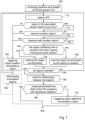
- Figure 4 illustrates an example of steps of an algorithm for detecting misbehaviour upon reception of a CPM.
- a first step is directed to receiving a CPM (step 400).
- the CPM may be received by an ITS-S through its ITS module.
- the CPM is a segment of a larger CPM, it is concatenated with one or more other segments to recreate a complete (or concatenated) CPM(step 405).
- This may be done by a misbehaviour analysis module. Indeed, as described with reference to Figure 3 , a complete CPM may be segmented in a set of CPMs, following CPM assembly rules. In such a case, these segments of CPMs contain part of the information and should be assembled together in order to reconstruct the entire scene. Concatenation of segments may be done on the basis that segments of a larger CPM have the same referenceTime indicated. If they have a different referenceTime, then they are not segments of the same set of CPMs and should not be concatenated. It should be noted that a complete CPM may be received at once. In such a case, there is no need for concatenation with other messages.
- step 405 it is also checked whether the complete received CPM or the segments of a complete CPM respect the CPM format rules. This may be done by comparing the content of the perceptionRegion (PR) instances with the assembly rules of the specification. If the CPM format rules are not respected, the emitting station is considered misbehaving and its CPMs may be ignored.
- the generation of a misbehaviour report is triggered and relative information is provided to a misbehaviour report generator which generates a misbehaviour report as described with reference to step 460 and by reference to Figure 12 . More generally, each time an inconsistency is detected, the generation of a misbehaviour report is triggered and relative information is sent to the misbehaviour report generator.
- Step 460 is in charge of generating a misbehaviour report as specified in ETSI specification, with observations and related V2X evidence (typically, the messages received) or non-V2X evidence.
- the CPM received at step 400 (if it is a complete CPM) or the concatenated message is then analysed to verify whether the perception regions contained into the message are respecting the specification rules of the perception regions, as described with reference to Figure 6 .
- This step may comprise a list of tests to be carried out on the perceivedObjectlds and numberOfPerceivedObjects fields. If they do not respect the specification rules, the ITS-S which originated the CPM (also called the originating ITS-S) is considered to be misbehaving and a report generation is triggered (step 460).
- the regions which are not respecting the specification are deleted.
- the message is then stored (step 415) for future usage.
- step 420 a test is carried out to check whether all the entries of the perceivedObjectlds field indicated in the perceptionRegion instances of the perceptionRegionContainer are referring to objectld fields in the perceivedObject instances listed in the PerceivedObjectContainer. If all the perceivedObjectlds entries indicated in the perceptionRegion instances of the perceptionRegionContainer are referring to objectld fields in the perceivedObject instances listed in the PerceivedObjectContainer, the algorithm moves on to step 435.
- the algorithm tries to recover the object properties through previous CPMs of the same source (step 425) if they exist, by linking the object identifiers listed in the perception regions to object identifiers listed in the perceived object container, as described with reference to Figure 8 .
- step 430 objects that are not present in an existing recent CPM should be considered as ghost objects, meaning that their identifiers are listed in a perceptionRegion instance but are referencing objects that have never been described in the perceivedObject container. In such a case, the emitter is considered to be misbehaving and a report generation is triggered.
- This step may be stopped if a ghost object is detected or, optionally, the identifier of the ghost object may be deleted and the step continues with the remaining objects (if any). If the algorithm fails to recover all objects, the algorithm may end or may continue with step 430. If it succeeds to recover all object properties, the algorithm continues with step 430.
- the properties (e.g., the size and/or the position) of the perceived objects contained in the perception regions are compared with the properties of these regions. For example, it may be determined whether all objects indicated in a region actually physically fit in the region according to its defined shape and size. If an inconsistency is detected, the emitter is considered to be misbehaving and a report generation is triggered.
- step 435 a test is carried out to determine whether there are other CPMs from the same source that are stored on the device. If there is not any other CPM from the same source that is stored on the device, the algorithm continues with step 440. On the contrary, if there are other CPMs from the same source that are stored on the device, the algorithm continues with step 445.
- step 440 perception regions from different sources are compared to each other in order to detect inconsistencies between sources.
- the perception regions may not be the same, it may be required to compute intersection areas of the regions from the different sources.
- tracking mechanisms could be used as fusion mechanisms to match the objects from different sources.
- some tests are carried out to check the consistency of objects in the regions from the different sources. If an inconsistency is detected, a misbehaviour report is triggered. On the contrary, if not any inconsistency is detected, the algorithm ends.
- step 455 it is determined whether the perception regions are the same between the messages. If the perception regions are not the same between the messages, the algorithm continues with a dynamic perception region temporal analysis in step 450. On the contrary, if the perception regions are the same between the messages, a temporal consistency analysis is carried out between messages with same perception regions (step 455, described in more detail in Figure 10 ).
- one region is crosschecked with the other regions, using the Intersection over Union (IoU) concept, where the area and position of a shape is compared to the area and position of another shape to get a percentage of matching. More precisely, the IoU between two shapes is calculated by dividing the area of intersection by the area of union. For example, the two same exact shapes would have an IoU of 100%. Again, the two exact same shapes but with a slightly different position would have a slightly lower IoU. On the other hand, a low IoU would mean two shapes are not good matches. Used with a threshold, the IoU can be used to identify similar shapes with a given tolerance. In this step, a threshold of 95% is used.
- IoU Intersection over Union
- step 450 the different regions are compared with each other.
- the ITS-S which is generating the perception regions might be moving, it is possible that the regions have the same shape but not the same position. Therefore, the IoU method does not provide good results in such a case and the shapes of the regions between the two messages may be compared as well as the relative shift of the coordinates with the shift of the ITS-S itself.
- the object properties like the coordinates, the speed, and the heading
- step 455 objects properties (e.g., the speed and/or the heading) are monitored with regard to the evolution of these objects between the messages with different emission timestamp thanks to tracking.
- the objective is to detect impossible behaviour of the objects between two messages. If an inconsistency is detected, the emitter is considered to be misbehaving and a report generation is triggered.
- Figure 5 illustrates an example of steps of an algorithm for concatenating CPMs, as described with reference 405 in Figure 4 .
- the steps illustrated in Figure 5 aim at detecting inconsistency between the format on the CPM received and the specification.
- a first step is directed to waiting for a CPM to be received (step 505).
- a test is carried out to determine whether the number of perception region instances in the message is less than or equal to the maximum of instances possible as described in the specification. If the number of perception region instances in the message is not less than or equal to the maximum of instances, a report generation indicting a format inconsistency is triggered (step 520). Next or if the number of perception region instances in the message is less than or equal to the maximum of instances, the algorithm continues on step 525.
- a concatenated message (or complete message) is different from a concatenation list of messages.
- a concatenated message may be considered as a unique CPM, which may comprise information contained in a set of segments, while a concatenation list of messages is a list composed of segments that will be concatenated as a unique message in the future.
- a concatenation list of messages is not closed and may be expanded with new CPM segments.
- a concatenation list of messages is to be closed when a CPM or a segment of CPM from the same source with a different timestamp is received. The concatenated message is then built from the list, and a new concatenation list of messages is created for the CPM which has just been received.
- step 525 It is checked, in step 525, whether a concatenation list of messages already exists for messages from the source of the received CPM. If a concatenation list of messages does not exist for messages from this source, a new concatenation list comprising the received CPM is created in step 530. Next, the algorithm continues on step 505 to wait for a new message. Accordingly to the illustrated example of steps, each source has a different concatenation list of messages.
- step 535 it is checked whether the message received has the same reference time as the segments which constitute the concatenation list of messages. If the reference time is the same, it means that a new segment from the same source has been received (since the segments of a CPM should all have the same reference time). In such a case, the algorithm continues on step 545. On the contrary, if the reference time is not the same, this means that a CPM from a new set of segments or eventually a complete CPM has been received. In such a case, it is determined whether there is at least one region described in the list of messages (step 538).
- the list is withdrawn in step 575 as it is of no interest in the context of the disclosure.
- the current concatenation list of messages is closed, all the segments of the list are saved (in case they need to be included in misbehaviour report evidence later), and the concatenated message is sent to another module to be checked (step 540), for example as described by reference to step 410 in Figure 4 .
- the CPM received in step 505 was already a complete CPM, it may be decided not to save it in this step since the complete CPM is stored in step 415. To avoid redundancy, only the segments of CPMs may be stored here.
- step 545 if the message received has the same reference time as the segments which constitute the concatenation list of messages, a test is carried out to identify the actual assembly mode of the CPM received.
- CPMs can be divided in segments according to two modes: object utility function and perception region based.
- the modules that generate and receive CPMs should know beforehand in which mode they, and their neighbours, are configured. For example, a RSU may prefer a perception region based configuration while an ITS-S may use an object utility function mode. Therefore, a test may be carried out to determine whether the source is consistent with its previous message as it should not change its assembly configuration without informing the members of the network. If the assembly mode is the object utility function mode, the algorithm continues on step 550 and if the assembly mode is the perception region based mode, the algorithm continues on step 555.
- step 550 it is checked whether the segment received is containing a perception region while a segment with at least one perception region has already been received. If the segment received is containing a perception region while a segment with at least one perception region has already been received, a message assembly inconsistency report is triggered in step 560. In addition, the current concatenation list of messages is withdrawn (step 565). Optionally, all the following messages from this source may be ignored.
- step 555 it is checked whether there is at least one perception regions described in the segment. If there is not any perception region described in the segment, a report generation is triggered in step 570. In addition, the current concatenation list of messages is withdrawn (step 575). Optionally, all the following messages from this source may be ignored.
- the CPM received is added to the current concatenation list (step 580).
- step 505 the algorithm loops on step 505 to process other CPMs received.
- the inconsistency report format may be based on the ETSI specification of Misbehaviour Reporting Service (as described with reference to Figure 11 ).
- the observation, v2xPduEvidence, and nonv2xPduEvidence may be listed in the report, as follows:
- Figure 6 illustrates an example of steps of an algorithm for analysing consistency between CPM perception region instances and predetermined rules, as described with reference 410 in Figure 4 .
- a first step is directed to a test for determining whether each of the perceived object identifiers is listed in no more than one region as it is a rule of the specification (step 605). If at least one perceived object identifier is listed in more than one region, a perception region rule inconsistency report is triggered (step 610). Since it cannot be determined which object identifier is to be deleted, the algorithm continues on step 615. On the contrary, if each of the perceived object identifiers is listed in no more than one region, the algorithm continues on step 615.
- Step 615 aims at identifying the dominating and dominated regions, as described in more detail by reference to Figure 7 .
- Table 2 in the Appendix provides an example of the relationships between the regions defined in the area illustrated in Figure 1 . According to this example, an identifier is provided to each region and for each region, the list of the identifiers of the regions that are contained in this region is given as well as the identifier of the region containing this region.
- step 615 some verifications regarding the positions of the regions are performed in step 615.
- Such verification could lead to inconsistency reports and/or to removal of the inconsistent regions within the message.
- the consistency of the object identifiers (perceivedObjectlds) and the number of objects (numberOfPerceivedObjects) fields may be carried out in each region and between the regions.
- step 620 all the regions that are only dominating regions, i.e., which contain no other region, are selected. For example, in Figure 1 , regions 115, 145, and 150 would be selected in step 620.
- the algorithm enters a loop to select each region of the set of regions selected in step 620, one after another. To that end, one region of the set (that has not been selected previously) is selected in step 625.
- a test is carried out to check whether the number of perceived objects (numberOfPerceivedObjects) of the selected region is equal to the number of object identifiers (perceivedObjectlds) of the selected region plus the number of object identifiers (perceivedObjectlds) indicated in the regions that dominate the selected region (step 630), if any. Since the selected region is a dominating only region, this test makes it possible to verify that the number of perceived object (numberOfPerceivedObjects) of the selected region is consistent with the number of object identifiers (perceivedObjectlds) of the selected region.
- a perception region dominance inconsistency report is triggered (step 635).
- an analysis module may be used to compare the results of the test carried out in step 630 for the other regions, to try to identify the problem (step 640).
- step 645 it is determined in step 645 whether all the regions of the set of regions determined in step 620 have been selected. If all the regions of the set of regions determined in step 620 have not been selected, the algorithm loops on step 625 to select another region of the set of regions. On the contrary, if all the regions of the set of regions determined in step 620 have been selected, the algorithm continues on step 650.
- step 650 it is determined whether some of the regions of the set of regions determined at step 620 are contained in one or more other regions. If none of the regions of the set of regions determined at step 620 is contained in another region, it means there are no other region to process and the algorithm ends. If the contrary, if some of the regions of the set of regions determined at step 620 are contained in one or more other regions, a new set of regions is determined, based on the regions that contain the regions of the previous set (step 660). Turning back to the regions of Figure 1 , the set comprising regions 102, 110, and 140 would be determined in step 660, after having processed each region of the set comprising regions 115, 145, and 150.
- a test is carried out to determine whether the new set of regions comprises one or more regions that are contained in regions which are also in the new set of regions (step 665). If the new set of regions comprises one or more regions that are contained in regions which are also in the new set of regions, the regions that are contained in regions which are also in the new set of regions are removed them from the set (step 670). Turning back to the regions of Figure 1 , region 110 would be removed from the new set of regions since region 140 is contained within region 110. Accordingly, the new set of regions would comprise only regions 102 and 140 after carrying out step 670. This step delays the test of a region containing other regions after the tests of all the regions it contains. Therefore, region 110 is selected and tested in the set of the next iteration.
- the algorithm loops on step 625 to check the regions of the new set of regions.
- step 640 By using an analysis module (step 640) which would compare the results of the test carried out in step 630 between iterations (positive or negative), it could be possible to have a clearer idea of the regions that have inconsistent numberOfPerceivedObjects and perceivedObjectlds fields, and which field is not correct.
- the suspected inconsistent regions may be deleted from the message.
- the inconsistency report format may be based on the ETSI specification of Misbehaviour Reporting Service (as described with reference to Figure 11 ).
- the observation, v2xPduEvidence, and nonv2xPduEvidence may be listed in the report, as follows:
- Figure 7 illustrates an example of steps of an algorithm for identifying dominating and dominated regions, as described with reference 615 in Figure 6 , and for crosschecking regions with each other and with the sensor FoVs to identify shape and/or position inconsistencies.
- a first step is directed to computing the positions and the shapes of the perception regions based on the information given by the perceptionRegionShape field of the perceptionRegion and sensorlnformation containers (step 705).
- a first region is selected for testing (step 710).
- step 715 the region position is crosschecked with its associated sensor FoV position.
- the aim of this step is to verify whether the selected region is in the FoV as it should be. If the selected region is not in the FoV, a report on region position inconsistency is triggered (step 730). If the selected region is in the FoV, the algorithm continues on step 720.
- step 730 After triggering the inconsistency report (step 730), the algorithm loops on step 710 to select and process another region.
- the inconsistent region may be deleted in step 760.
- the algorithm may end or loops on step 710 to select and process another region.
- the selected region is crosschecked with the other regions, using for example the Intersection over Union (IoU) mechanism.
- IoU Intersection over Union
- a minimum threshold for example a minimum threshold set to 95%, may be set to consider that two shapes are the same.
- the aim of comparing the selected region with the others is to determine whether the selected region is already existing (step 720) or whether the selected region is partially contained in (or intersects with) another region (step 725). In both cases, if an inconsistency is detected, an inconsistency report is triggered (i.e., the algorithm goes to step 730).
- step 740 it is marked as dominated by the regions it contains (step 740). On the contrary, if the selected region does not contain any other region, the selected region is marked as dominating (step 745).
- step 750 it is determined whether all the regions have been selected. If all the regions have not been selected, the algorithm loops on step 710 to select and process another region. On the contrary, if each region has been selected, the algorithm continues on step 755.
- the relationships between the regions are built (step 755).
- the dominating regions may be linked to their dominated regions as proposed in Table 2 in the Appendix.
- step 765 Another test may be carried out on the perceptionRegion measurementDeltaTime (step 765) to verify that the dominating regions have been added later to the container than the regions they dominate (i.e., that the dominating regions have a delta time superior to the region they dominate). If one or more dominating regions have been added sooner than a region they dominate, a region deltaTime inconsistency is built (step 770).
- the inconsistency report format may be based on the ETSI specification of Misbehaviour Reporting Service (as described with reference to Figure 11 ).
- the observation, v2xPduEvidence, and nonv2xPduEvidence may be listed in the report, as follows:
- Figure 8 illustrates an example of steps of an algorithm for recovering objects, as described with reference 425 in Figure 4 .
- the aim of the steps illustrated in Figure 8 is to link all the object identifiers (perceivedObjectlds) listed in the perceptionRegion instances to the objectld field of the perceivedObject instances in order to check whether the objects exist and to recover object properties for further analysis, it being observed that according to the CPM specification, perceived objects may be absent from CPMs for a maximum time of T_GenCpmMax/2 for the Type-A objects and T_GenCpmMax for the Type-B objects. After this time period, they should be included in the next CPM which should be sent in T_GenCpm (at the next CPM generation event).
- a first step is directed to determining whether a previous CPM from the same source is stored (step 805). If not any previous CPM from the same source is stored, the algorithm ends as it is not actually possible to recover information on the object since no previous CPM from this source has been saved. Optionally, the algorithm may continue on step 435 in Figure 4 , knowing that not all objects were recovered. On the contrary, if a previous CPM from the same source is stored, a test is carried out to determine whether the CPM was emitted before the reference time of the received CPM minus T_GenCpmMax and T_GenCpm, representing respectively the maximum time an object can be omitted and the time between the generation of two CPMs.
- the object identifiers indicated in the perception region of the recently received CPM are referencing objects that are not described in previous CPMs according to the specification. Accordingly, the objects cannot be recovered and thus, a ghost object report is triggered (step 815). It is then possible to end the algorithm as it failed to recover all objects. Alternately, the identifiers of the ghost objects may be removed from the perception region of the CPM (step 825) so that the algorithm continues on step 435 in Figure 4 .
- step 830 it is determined whether a perceivedObjectlds entry of the perceptionRegion instance may be found in the perceivedObject instances. To that end, it is determined whether the perceivedObjectlds entry is equal to one of the values of the objectID field of the perceivedObject instances. If the perceivedObjectlds entry is not equal to any of the objectID of the perceivedObject instances, the algorithm loops on step 805 and an older CPM from the same source is selected, if any. If the perceivedObjectlds entry is equal to one of the objectID of the perceivedObject instances, the perceptionRegion object id is linked to the perceived object in step 835, in order to use its information and properties later.
- step 830 it is checked whether all the object identifiers of all the perceptionRegion instances are linked to a perceivedObject instance. If all the object identifiers of all the perceptionRegion instances are linked to a perceivedObject instance, the algorithm ends. On the contrary, if at least one object identifier of all the perceptionRegion instances is not linked to a perceivedObject instance, the algorithm loops on step 830 to select and test another entry of a perceivedObjectlds.
- v2xPduEvidence may be listed in the report, as follows:
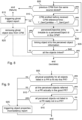
- Figure 9 illustrates an example of steps of an algorithm for comparing physical properties of objects, for example of the objects recovered in steps 420 and/or 425 of Figure 4 , to physical properties of the regions that contain these objects, as described with reference 430 in Figure 4 .
- a first step is directed to determining whether the objects contained in a perceptionRegion instance may all fit in the perception region their identifiers are listed in, in view of their size (step 905). If the objects contained in a perceptionRegion instance cannot all fit in the perception region their identifiers are listed in, a property inconsistency report is triggered (step 925).
- a property inconsistency report is triggered (step 925).
- step 915 another test is carried out to determine whether the objects in the perceivedObjectContainer that are not listed in a perceptionRegion instance should be listed in a perceptionRegion instance, in view of their coordinates (step 915). If the objects in the perceivedObjectContainer that are not listed in a perceptionRegion instance should be listed in a perceptionRegion instance, a property inconsistency report is triggered (step 925). On the contrary, if the objects in the perceivedObjectContainer that are not listed in a perceptionRegion instance should not be listed in a perceptionRegion instance, the algorithm ends.
- step 925 After triggering a property inconsistency report (step 925), the algorithm ends.
- v2xPduEvidence may be listed in the report, as follows:
- Figure 10 illustrates an example of steps of an algorithm for checking temporal consistency of CPMs, as described with reference 455 in Figure 4 .
- the aim of these steps is to detect impossible behaviour from the perceived objects between two messages emitted from the same source but at a different timestamp (referenceTime).
- Object properties like the speed or heading are used to track the object presence or absence in the regions of the previous message.
- a first step is directed to selecting a first perception region (step 1005).
- the identifiers of the objects listed in the selected perception region of the current and in the previous message are compared (step 1010). In particular, it is determined whether an object has disappeared from the selected perception region. If at least one object has disappeared from the selected perception region, the algorithm continues on step 1015. On the contrary, if not any object has disappeared from the selected perception region, the algorithm continues on step 1045.
- a test is carried out to determine whether this object is now in another perception region (step 1015). If the object that disappeared is not in another perception region, another test is carried out to determine whether this object could actually be out of the sensor FoV (step 1025), in view of its speed and heading at the timestamp of the previous message. If this object could actually be out of the sensor FoV, the algorithm continues on step 1045. On the contrary, if this object could not actually be out of the sensor FoV, meaning that an object has disappeared from the selected perception region and it should not have, a temporal inconsistency report is triggered (step 1030).
- step 1035 another test is carried out to determine whether this object which is in another region could have changed of regions in the elapsed time between the messages (step 1035), in view of the object speed and heading and the road configuration. For example, if the old and the new region it has been seen in are actually separated by a barrier (as for example in Figure 1 , with regions 102 and 110), it might not be physically possible, depending on the elapsed time between the messages. If such a change was not possible, a temporal inconsistency report is triggered (step 1030).
- step 1025 If the object that disappeared is not in another region and could actually be out of the sensor FoV (step 1025), if the object that disappeared is in another region and could have changed of regions in the elapsed time between the messages (step 1035), or if not any object disappeared from the selected perception region (step 1010), an object is selected among the objects listed in the selected perception region.
- step 1050 the contents of the two messages are compared to determine whether the selected object was already in the same perception region. If the selected object was already in the same perception region, another test is carried out to determine whether the object, which is still in the same region, should have changed of regions in the elapsed time (step 1055), in view of its speed and heading in the previous message. If the object should have changed of regions in the elapsed time, a temporal inconsistency report is triggered (step 1065). If the object should not have changed of regions in the elapsed time or after having triggered a temporal inconsistency report, the algorithm continues on step 1085.
- step 1050 another test is carried out to determine whether the selected object was in another perception region (step 1060). If the selected object which was not in the selected perception region was in another perception region at the timestamp of the previous message, another test is carried out to determine whether the object which has changed of the region could have physically change of region between the two messages in view of its speed, heading, and the road configuration (step 1070). If this object could not have physically change of region between the two messages, a temporal inconsistency report is triggered (step 1075). If this object could have physically change of region between the two messages or after having triggered a temporal inconsistency report, the algorithm continues on step 1085.
- step 1060 If the selected object which was not in the selected perception region was not in another perception region at the timestamp of the previous message (step 1060), another test is carried out to determine whether the selected object could have been outside of the sensor FoV (step 1080), in view of its speed and heading. If the selected object could not have been outside of the sensor FoV, meaning that the object has appeared from nowhere, a temporal inconsistency report is triggered (step 1075). If the selected object could have been outside of the sensor FoV or after having triggered a temporal inconsistency report, the algorithm continues on step 1085.
- step 1085 a test is carried out to determine whether all the objects of the selected perception region have been selected. If at least one object of the selected perception region has not been selected, the algorithm loops on step 1045 to select an object of the selected perception region that has not been selected yet. On the contrary, if all the objects of the selected perception region have been selected, the algorithm continues on step 1090 where it is determined whether all the perception regions of the current message have been selected. If at least one perception region of the current message has not been selected, the algorithm loops on step 1005 to select a perception region that has not been selected yet. On the contrary, if all the perception regions of the current message have been selected, the algorithm ends.
- the inconsistency report format may be based on the ETSI specification of Misbehaviour Reporting Service (as described with reference to Figure 11 ).
- the observation, v2xPduEvidence, and nonv2xPduEvidence may be listed in the report, as follows:
- Figure 11 illustrates the misbehaviour report format, as defined in the ETSI Misbehaviour Reporting Service.
- the misbehaviour report is a message that comprises, after decryption, a version 1105, a generationTime 1110, an observation Location 1115 referring to the place where the misbehaviour was detected, and finally a report 1120.
- the report contains an aid (application id) 1125 and a content data field 1130.
- a set of possible observations with their target properties are defined.
- the list of possible non V2X evidences is defined by the application. This is achieved thanks to Information Object Class and Information Object Set concepts. The aid selects the set of observations and non V2X evidence specific to an application.
- Content field 1130 refers to the content data field which contains the observations 1135, the v2xPduEvidence 1145, and the sequence of nonV2xPduEvidence 1155.
- observations 1135 is composed of a sequence of ObservationsByTarget 1140.
- This data type contains all of the observations related to a particular "target" property, such as a speed or a security level, for example as follows:
- v2xPduEvidence 1145 is composed of a sequence of V2xPduStream 1150.
- This data type contains PDU stream from a single sender, for example as follows:
- nonV2xPduEvidence 1155 is composed of a sequence of NonV2xPduEvidenceltem 1160.
- This data type contains evidence, which may be referenced by one or more observations, for example as follows:
- a set of target property for the AsrCpm in which the observations issued from perception region inconsistencies are classified may be defined as follows:
- Figure 12 illustrates an example of steps of an algorithm for generating a misbehaviour report, as described with reference 460 in Figure 4 . These steps are carried out when a misbehaviour generation is triggered.
- the construction of the misbehaviour report begins with the choice of the CPM application a set of observations to be selected is defined for the CPMs (more particularly, to the perception regions of CPMs). Therefore, the AsrCpm class of information is selected to build the misbehaviour report (step 1205).
- the appropriate observation property target relevant to the misbehaviour detected is selected and included in the misbehaviour report (step 1210)
- the appropriate observation (part of the target property observations list) relevant to the misbehaviour detected is selected and included in the misbehaviour report (step 1215)
- the relevant evidence is included in the misbehaviour report (step 1220).
- the evidence may be completed with optional information if the pieces of evidence are relevant and not redundant.
- the misbehaviour report is encrypted (step 1225) before being sent to the relevant authorities like the MA (step 1230).
- Figure 13 illustrates an example of steps of an algorithm for receiving and processing a misbehaviour report. These steps may be carried out in the device illustrated in Figure 2c , for example a MA.
- a misbehaviour report is decrypted (step 1305).
- step 1310 a test is carried out to determine whether the reporter certificate is valid (looking at its aid, its ssp, the validity region, the validity period, etc.).
- step 1320 If the misbehaviour report received is actually a misbehaviour report, another test is carried out to determine whether the aid references a valid application (step 1320).
- step 1325 If the aid references a valid application, another test is carried out to determine whether the aid is the CPM one (step 1325).
- the misbehaviour report is analysed as a function of its application field (step 1328) and the algorithm ends.
- step 1330 Another test is carried out to determine whether the target id references a valid target property (step 1330).
- step 1335 If the target id references a valid target property, another test is carried out to determine whether the observations made are part of the CPM observations and more particularly if the observation is part of the target property observation list (step 1335).
- step 1345 If all the evidence needed is included in the misbehaviour report and that not any irrelevant information is provided, another test is carried out to determine whether the reported ITS has a valid certificate (step 1345).
- ITS If the reported ITS has a valid certificate, a message is generated for the appropriate authorities (e.g., road operators, police, certificate authorities, local infrastructure) in step 1350.
- authorities e.g., road operators, police, certificate authorities, local infrastructure
- step 1350 a message is generated for the appropriate authorities (e.g., road operators, police, certificate authorities, local infrastructure).
- authorities e.g., road operators, police, certificate authorities, local infrastructure.
- Figure 14 is a schematic representation of an example of a communication ITS-S device configured to implement some embodiments of the present disclosure. It may be either an ITS-S embedded in a vehicle or in a road side entity.
- the communication device 1400 may preferably be a device such as a microcomputer, a workstation or a light portable device.
- the communication device 1400 comprises a communication bus 1413 to which there are preferably connected:
- the communication device 1400 may also include the following components:
- the communication device 1400 may be optionally connected to various peripherals including perception sensors 1408, such as for example a digital camera, each being connected to an input/output card (not shown) so as to supply data to the communication device 1400.
- perception sensors 1408 such as for example a digital camera
- input/output card not shown
- the communication bus provides communication and interoperability between the various elements included in the communication device 1400 or connected to it.
- the representation of the bus is not limiting and in particular the central processing unit is operable to communicate instructions to any element of the communication device 1400 directly or by means of another element of the communication device 1400.
- the disk 1406 may optionally be replaced by any information medium such as for example a compact disk (CD-ROM), rewritable or not, a ZIP disk, a USB key or a memory card and, in general terms, by an information storage means that can be read by a microcomputer or by a microprocessor, integrated or not into the apparatus, possibly removable and adapted to store one or more programs whose execution enables a method according to the disclosure to be implemented.
- CD-ROM compact disk
- ZIP disk a digital versatile disk
- USB key or a memory card
- an information storage means that can be read by a microcomputer or by a microprocessor, integrated or not into the apparatus, possibly removable and adapted to store one or more programs whose execution enables a method according to the disclosure to be implemented.
- the executable code may optionally be stored either in read-only memory 1407, on the hard disk 1404 or on a removable digital medium such as for example a disk 1406 as described previously.
- the executable code of the programs can be received by means of the communication network, via the interface 1402, in order to be stored in one of the storage means of the communication device 1400, such as the hard disk 1404, before being executed.
- the central processing unit 1411 is preferably adapted to control and direct the execution of the instructions or portions of software code of the program or programs according to the disclosure, which instructions are stored in one of the aforementioned storage means.
- the program or programs that are stored in a nonvolatile memory for example on the hard disk 1404 or in the read-only memory 1407, are transferred into the random access memory 1412, which then contains the executable code of the program or programs, as well as registers for storing the variables and parameters necessary for implementing the disclosure.
Landscapes
- Business, Economics & Management (AREA)
- Engineering & Computer Science (AREA)
- Human Resources & Organizations (AREA)
- Signal Processing (AREA)
- Computer Networks & Wireless Communication (AREA)
- Economics (AREA)
- Strategic Management (AREA)
- Tourism & Hospitality (AREA)
- Theoretical Computer Science (AREA)
- General Business, Economics & Management (AREA)
- Marketing (AREA)
- General Physics & Mathematics (AREA)
- Physics & Mathematics (AREA)
- General Health & Medical Sciences (AREA)
- Primary Health Care (AREA)
- Health & Medical Sciences (AREA)
- Development Economics (AREA)
- Educational Administration (AREA)
- Entrepreneurship & Innovation (AREA)
- Game Theory and Decision Science (AREA)
- Operations Research (AREA)
- Quality & Reliability (AREA)
- Management, Administration, Business Operations System, And Electronic Commerce (AREA)
- Mobile Radio Communication Systems (AREA)
Applications Claiming Priority (1)
| Application Number | Priority Date | Filing Date | Title |
|---|---|---|---|
| GB2313683.1A GB2633369A (en) | 2023-09-07 | 2023-09-07 | Method, device, and computer program for improving communication in an intelligent transport system |
Publications (1)
| Publication Number | Publication Date |
|---|---|
| EP4521784A1 true EP4521784A1 (de) | 2025-03-12 |
Family
ID=88412770
Family Applications (1)
| Application Number | Title | Priority Date | Filing Date |
|---|---|---|---|
| EP24198456.6A Pending EP4521784A1 (de) | 2023-09-07 | 2024-09-04 | Verfahren, vorrichtung und computerprogramm zur verbesserung der kommunikation in einem intelligenten transportsystem |
Country Status (2)
| Country | Link |
|---|---|
| EP (1) | EP4521784A1 (de) |
| GB (1) | GB2633369A (de) |
Citations (2)
| Publication number | Priority date | Publication date | Assignee | Title |
|---|---|---|---|---|
| US20220095115A1 (en) * | 2020-09-22 | 2022-03-24 | Toyota Motor Engineering & Manufacturing North America, Inc. | Misbehavior detection for vehicle-to-everything messages |
| WO2022235973A1 (en) * | 2021-05-07 | 2022-11-10 | Intel Corporation | Misbehavior detection using data consistency checks for collective perception messages |
-
2023
- 2023-09-07 GB GB2313683.1A patent/GB2633369A/en active Pending
-
2024
- 2024-09-04 EP EP24198456.6A patent/EP4521784A1/de active Pending
Patent Citations (2)
| Publication number | Priority date | Publication date | Assignee | Title |
|---|---|---|---|---|
| US20220095115A1 (en) * | 2020-09-22 | 2022-03-24 | Toyota Motor Engineering & Manufacturing North America, Inc. | Misbehavior detection for vehicle-to-everything messages |
| WO2022235973A1 (en) * | 2021-05-07 | 2022-11-10 | Intel Corporation | Misbehavior detection using data consistency checks for collective perception messages |
Also Published As
| Publication number | Publication date |
|---|---|
| GB202313683D0 (en) | 2023-10-25 |
| GB2633369A (en) | 2025-03-12 |
Similar Documents
| Publication | Publication Date | Title |
|---|---|---|
| CN111881244B (zh) | 用于使v2x技术与加密和/或加偏转的高精度地图匹配的方法和设备 | |
| Bißmeyer et al. | Assessment of node trustworthiness in vanets using data plausibility checks with particle filters | |
| US10839682B1 (en) | Method and system for traffic behavior detection and warnings | |
| CN111415528A (zh) | 道路安全预警方法、装置、路侧单元及存储介质 | |
| US12573290B2 (en) | Road space collective perception message within an intelligent transport system | |
| US20190039612A1 (en) | Technologies To Facilitate Automated Driving Assistance Based On Objects Sensed And Reported By Remote Senders | |
| WO2021159488A1 (en) | A method of vehicle permanent id report triggering and collecting | |
| JP7558226B2 (ja) | レイヤ化されたマップに基づくcpmにおける高度化された報告 | |
| EP4521784A1 (de) | Verfahren, vorrichtung und computerprogramm zur verbesserung der kommunikation in einem intelligenten transportsystem | |
| EP4408039A1 (de) | Verbesserte signalisierung von wahrgenommenen objekten in einem intelligenten transportsystem | |
| US20240005180A1 (en) | Communications within an intelligent transport system to anticipate the behavior of mobile objects | |
| US12424094B2 (en) | Communication within an intelligent transport system | |
| EP4307269A1 (de) | Verbesserte kommunikation in einem intelligenten transportsystem | |
| GB2607376A (en) | Reporting method within an intelligent transport system | |
| US12488680B2 (en) | Communication within an intelligent transport system for signaling hidden objects | |
| US20240257635A1 (en) | Reporting method within an intelligent transport system | |
| GB2634088A (en) | Method, device, and computer program for monitoring proper operation of sensors within an intelligent transport system | |
| GB2612655A (en) | Road space collective perception message within an intelligent transport system | |
| EP4387281A1 (de) | Verbesserte cluster-breakup-verwaltung in einem intelligenten transportsystem | |
| GB2644322A (en) | Method, device, and computer program for improving safety in an intelligent transport system | |
| Caballero-Gil et al. | Ubiquitous collision avoidance system for red light running | |
| JP7548430B2 (ja) | 車両用装置及び誤差推定方法 | |
| EP4521378A1 (de) | Verfahren, vorrichtung und computerprogramm zur verbesserung der manöverkoordination in einem intelligenten transportsystem | |
| GB2631728A (en) | Method and apparatus for reporting a perception region | |
| US20220140963A1 (en) | Communication method and apparatus |
Legal Events
| Date | Code | Title | Description |
|---|---|---|---|
| PUAI | Public reference made under article 153(3) epc to a published international application that has entered the european phase |
Free format text: ORIGINAL CODE: 0009012 |
|
| STAA | Information on the status of an ep patent application or granted ep patent |
Free format text: STATUS: REQUEST FOR EXAMINATION WAS MADE |
|
| 17P | Request for examination filed |
Effective date: 20240904 |
|
| AK | Designated contracting states |
Kind code of ref document: A1 Designated state(s): AL AT BE BG CH CY CZ DE DK EE ES FI FR GB GR HR HU IE IS IT LI LT LU LV MC ME MK MT NL NO PL PT RO RS SE SI SK SM TR |
|
| STAA | Information on the status of an ep patent application or granted ep patent |
Free format text: STATUS: EXAMINATION IS IN PROGRESS |
|
| 17Q | First examination report despatched |
Effective date: 20250916 |