EP4521612A1 - Hairpin coil cooling structure for hairpin winding motor - Google Patents
Hairpin coil cooling structure for hairpin winding motor Download PDFInfo
- Publication number
- EP4521612A1 EP4521612A1 EP24190496.0A EP24190496A EP4521612A1 EP 4521612 A1 EP4521612 A1 EP 4521612A1 EP 24190496 A EP24190496 A EP 24190496A EP 4521612 A1 EP4521612 A1 EP 4521612A1
- Authority
- EP
- European Patent Office
- Prior art keywords
- spray
- hairpin
- cooling oil
- body portion
- winding motor
- Prior art date
- Legal status (The legal status is an assumption and is not a legal conclusion. Google has not performed a legal analysis and makes no representation as to the accuracy of the status listed.)
- Granted
Links
Images








Classifications
-
- H—ELECTRICITY
- H02—GENERATION; CONVERSION OR DISTRIBUTION OF ELECTRIC POWER
- H02K—DYNAMO-ELECTRIC MACHINES
- H02K9/00—Arrangements for cooling or ventilating
- H02K9/19—Arrangements for cooling or ventilating for machines with closed casing and closed-circuit cooling using a liquid cooling medium, e.g. oil
-
- H—ELECTRICITY
- H02—GENERATION; CONVERSION OR DISTRIBUTION OF ELECTRIC POWER
- H02K—DYNAMO-ELECTRIC MACHINES
- H02K1/00—Details of the magnetic circuit
- H02K1/06—Details of the magnetic circuit characterised by the shape, form or construction
- H02K1/22—Rotating parts of the magnetic circuit
- H02K1/32—Rotating parts of the magnetic circuit with channels or ducts for flow of cooling medium
-
- H—ELECTRICITY
- H02—GENERATION; CONVERSION OR DISTRIBUTION OF ELECTRIC POWER
- H02K—DYNAMO-ELECTRIC MACHINES
- H02K3/00—Details of windings
- H02K3/04—Windings characterised by the conductor shape, form or construction, e.g. with bar conductors
- H02K3/24—Windings characterised by the conductor shape, form or construction, e.g. with bar conductors with channels or ducts for cooling medium between the conductors
-
- H—ELECTRICITY
- H02—GENERATION; CONVERSION OR DISTRIBUTION OF ELECTRIC POWER
- H02K—DYNAMO-ELECTRIC MACHINES
- H02K2203/00—Specific aspects not provided for in the other groups of this subclass relating to the windings
- H02K2203/09—Machines characterised by wiring elements other than wires, e.g. bus rings, for connecting the winding terminations
-
- H—ELECTRICITY
- H02—GENERATION; CONVERSION OR DISTRIBUTION OF ELECTRIC POWER
- H02K—DYNAMO-ELECTRIC MACHINES
- H02K2209/00—Specific aspects not provided for in the other groups of this subclass relating to systems for cooling or ventilating
Definitions
- the present invention relates to a cooling structure for a hairpin winding motor, and more particularly, to a hairpin coil cooling structure for a hairpin winding motor, which is capable of improving performance in cooling a hairpin coil by spraying oil to a rotor plate, which is a component of a motor, and dispersing the cooling oil by rotating the rotor plate.
- the output of the motor is proportional to the number of turns of a coil wound around a stator core. Therefore, a method of increasing a space factor of the coil wound around the stator core may be considered to improve the output of the motor without increasing a size of the motor.
- a motor hereinafter, referred to as a 'hairpin winding motor'
- a 'hairpin winding motor in which a plurality of separated hairpins is inserted and fastened into a stator coil, and then the hairpins are joined by welding to define a coil winding part.
- FIG. 1 illustrates a general hairpin winding motor 10
- FIG. 2 is a cross-sectional view illustrating the general hairpin winding motor 10.
- a coil winding part of a stator core 12 is formed by fastening hairpin coils 13, which are formed in an approximately 'U' or 'V' shape, into slots of the stator core 12 disposed inside a housing 11 and then joining and welding the hairpin coils 13 disposed on layers of the slots. Therefore, the hairpin winding motor 10 facilitates the operation of winding the angular coil while overcoming mechanical limitations caused by a winding machine.
- the housing 11 further includes an oil injection tube 15 through which cooling oil is supplied into the housing 11 to cool the hairpin winding motor 10 that generates heat.
- the cooling oil introduced into the housing 11 flows, as indicated by the arrows, because of rotor plates (not illustrated) disposed at one open side 12a and the other open side 12b of the stator core 12, and the cooling oil is supplied and circulated only to a radially outer side of the hairpin coil 13, which causes a problem of deterioration in performance in cooling the coil disposed radially inward.
- the present invention is proposed to solve these problems and aims to provide a hairpin coil cooling structure for a hairpin winding motor, which is capable of improving performance in cooling a radially inner coil, among hairpin coils, adjacent to a rotor that generates the largest amount of heat in the motor.
- the present invention also aims to provide a hairpin coil cooling structure for a hairpin winding motor, which is capable of spraying cooling oil to a rotor plate and rotating the rotor plate so that the cooling oil dispersed by a rotation of the rotor plate is sprayed to an inner coil.
- An embodiment of the present invention provides a hairpin coil cooling structure for a hairpin winding motor including a stator having a plurality of slots formed through the stator in a circumferential direction thereof and each having a plurality of layers in a radial direction thereof, and a plurality of hairpin coils fastened to the slots and connected to one another to define a coil winding
- the winding motor includes: a rotor rotatably mounted inside the stator; a rotor shaft connected to the rotor; a pair of rotor plates respectively provided at a first end portion and a second end portion of the rotor shaft and configured to cover a first open side and a second open side of the stator; and an oil injection tube configured to spray a cooling oil into the winding motor, in which a nozzle, which is provided at an end of the cooling oil injection tube to spray the cooling oil to an outer surface of the rotor plate, is disposed to be directed toward the outer surface of the rotor plate, and in which the cooling oil s
- the rotor plate may include: a circular body portion having a center penetrated by the rotor shaft; a spray portion protruding outward from an outer surface of the circular body portion, formed at a radially center of the circular body portion, and formed in a circumferential direction thereof; a spray groove formed in a radially inner surface of the spray portion and recessed radially outward; and a spray hole formed in the spray groove and formed through the radially inner surface and an outer surface of the spray portion, a spray surface configured to spray the cooling oil may be formed on the outer surface of the circular body portion, and the spray surface may be formed at a radially inner side of the spray portion.
- cooling oil injection tube may further include an auxiliary nozzle formed on the cooling oil injection tube and directed toward the inner coil to spray the supplied cooling oil directly to the inner coil.
- the rotor plate may include: a circular body portion having a center penetrated by the rotor shaft; a spray portion protruding outward from an outer surface of the circular body portion, formed at a radially center of the circular body portion, and formed in a circumferential direction thereof; a first spray groove formed in a radially inner surface of the spray portion, disposed adjacent to the outer surface of the circular body portion, and recessed radially outward; a second spray groove formed in the radially inner surface of the spray portion, disposed to be spaced apart from the outer surface of the circular body portion, and recessed radially outward; a spray hole formed in the second spray groove and formed through the radially inner surface and an outer surface of the spray portion; a partition wall formed to separate the first spray groove and the second spray groove; and connection grooves formed in the partition wall so that the cooling oil distributed in the first spray groove moves to the second spray groove, a spray surface configured to spray the cooling oil may be formed on the outer surface of the circular body portion, and
- connection grooves may be formed at predetermined distances in the circumferential direction and recessed radially inward, the connection groove may be formed adjacent to the spray hole, and a depth of the connection groove may be smaller than a depth of each of the first and second spray grooves.
- the spray hole may be disposed to be spaced apart from a position, at which the connection groove is formed, by a first angle ⁇ in a direction opposite to the rotation of the rotor plate.
- connection groove may be inclined at a second angle a with respect to a rotation axis of the rotor plate in a rotation direction of the rotor plate.
- the spray hole may be provided as a plurality of spray holes disposed to be spaced apart from one another in the circumferential direction of the spray portion.
- auxiliary nozzle may be provided as a plurality of auxiliary nozzles disposed to be spaced apart from one another in a longitudinal direction of the cooling oil injection tube.
- FIG. 3 is a front perspective view of a hairpin winding motor 100 according to an embodiment of the present invention
- FIG. 4 is a rear perspective view of the hairpin winding motor 100 according to the embodiment of the present invention.
- a coil winding part of a stator 120 is formed by fastening hairpin coils 130, which are formed in an approximately 'U' or 'V' shape, into slots of the stator 120 and then joining and welding the hairpin coils 130 disposed on layers of the slots.
- a rotor (not illustrated) is rotatably mounted inside the stator 120.
- a rotor shaft 190 is connected to the rotor.
- a rotor plate 150 is provided at one end of the rotor shaft 190 and covers one open side of the stator 120.
- a rotor plate 150-1 is provided at the other end of the rotor shaft 190 and covers the other open side of the stator 120.
- the present invention is characterized in that a part of oil introduced into the hairpin winding motor 100 is scattered toward a radially inner side of the hairpin coil 130 by the rotor plate 150 that rotates in conjunction with the rotor shaft 190.
- a detailed configuration of the hairpin winding motor 100 for implementing the above-mentioned characteristics will be described in detail with reference to the drawings.
- FIG. 5 is a partially enlarged perspective view of the hairpin winding motor 100 according to the embodiment of the present invention.
- the rotor plate 150 is provided at one open side of the stator 120 and coupled to the rotor shaft 190.
- the winding motor 100 includes an oil injection tube 160 configured to supply cooling oil into the winding motor 100.
- the cooling oil injection tube 160 has a nozzle formed at an end thereof to supply (spray) the cooling oil to one surface 151a of the rotor plate 150, and the nozzle is disposed to be directed toward one surface of the rotor plate 150.
- the following configuration is provided to supply the oil, which is supplied to one surface 151a of the rotor plate 150, to an inner coil 132 positioned at a radially inner side among the hairpin coils 130.
- FIG. 6 is a perspective view and a cross-sectional inner side view of the rotor plate 150 according to a first embodiment of the present invention.
- the rotor plate 150 includes a circular plate-shaped body portion 151 having a hollow portion formed at a center thereof so that the rotor shaft penetrates the circular body portion 151, and a spray portion 152 protruding from one surface of the circular body portion 151 toward one side.
- the spray portion 152 is formed on a radially central portion of the circular body portion 151 and formed in a circumferential direction.
- a spray groove 153 is formed in a radially inner surface of the spray portion 152 and recessed radially outward, and the spray groove 153 is also formed in the circumferential direction.
- spray holes 155 are formed in the spray groove 153 and formed through the radially inner surface and an outer surface of the spray portion 152.
- the spray holes 155 may be provided as a plurality of spray holes 155 disposed to be spaced apart from one another in the circumferential direction.
- a spray surface 151a is formed on one surface of the circular body portion 151, and the spray surface 151a may be formed at a radially inner side of the spray portion 152. Therefore, when the rotor plate 150 rotates, the cooling oil supplied to the spray surface 151a through the cooling oil injection tube 160 is distributed in the circumferential direction on the spray groove 153 of the spray portion 152 by a centrifugal force, and the cooling oil is sprayed in the circumferential direction toward a radially outer side of the spray portion 152 through the spray holes 155. Meanwhile, because the inner coils 132 positioned at the radially inner side among the hairpin coils 130 are disposed adjacent to the outer side of the rotor plate 150, the sprayed oil may be scattered toward the inner coils 132.
- FIG. 7 is a partially enlarged perspective view of the hairpin winding motor having an oil injection tube 260 according to another embodiment of the present invention.
- FIG. 8 is a perspective view illustrating the cooling oil injection tube 260 according to another embodiment of the present invention.
- the rotor plate 150 is provided at one open side of the stator 120 and coupled to the rotor shaft 190.
- the winding motor 100 includes the cooling oil injection tube 260 configured to supply cooling oil into the winding motor 100.
- the cooling oil injection tube 260 has a nozzle formed at an end thereof to supply (spray) the cooling oil to one surface 151a of the rotor plate 150, and the nozzle is disposed to be directed toward one surface of the rotor plate 150.
- the cooling oil injection tube 260 according to another embodiment of the present invention has the following configuration to spray the supplied cooling oil directly to the inner coil 132 positioned at the radially inner side among the hairpin coils 130.
- Auxiliary nozzles 265 may be further provided on the cooling oil injection tube 260, and the auxiliary nozzles 265 are disposed toward the inner coil 132 positioned at the radially inner side among the hairpin coils 130.
- the auxiliary nozzles 265 may be provided as a plurality of auxiliary nozzles 265 disposed to be spaced apart from one another in a longitudinal direction of the cooling oil injection tube 260. Therefore, in the present embodiment, the cooling oil may be scattered toward the inner coil 132 by the rotor plate 150, and at the same time, the cooling oil may be sprayed directly to the inner coil 132 through the auxiliary nozzles 265, thereby increasing an area of the cooling oil sprayed to the inner coil 132.
- FIG. 9 is a perspective view and a cross-sectional inner side view of a rotor plate 250 according to a second embodiment of the present invention
- FIG. 10 is a partially enlarged perspective view illustrating an oil flow path of the rotor plate 250 according to the second embodiment of the present invention.
- the rotor plate 250 includes a circular plate-shaped body portion 251 having a hollow portion formed at a center thereof so that the rotor shaft penetrates the circular body portion 251, and a spray portion 252 protruding from one surface of the circular body portion 151 toward one side.
- the spray portion 252 is formed on a radially central portion of the circular body portion 251 and formed in the circumferential direction.
- First and second spray grooves 253 and 254 are formed in a radially inner surface of the spray portion 252 and recessed radially outward, and the first and second spray grooves 253 and 254 are also formed in the circumferential direction.
- the first spray groove 253 is disposed adjacent to one surface 251a of the circular body portion 251, and the second spray groove 254 is disposed to be spaced apart from one surface 251a.
- the first spray groove 253 and the second spray groove 254 are separated by a partition wall 256.
- spray holes 255 are formed in the second spray groove 254 and formed through the radially inner surface and an outer surface of the spray portion 252.
- the spray holes 255 may be provided as a plurality of spray holes 255 disposed to be spaced apart from one another in the circumferential direction.
- a spray surface 251a is formed on one surface of the circular body portion 251, and the spray surface 251a may be formed at a radially inner side of the spray portion 252. Therefore, when the rotor plate 250 rotates, the cooling oil supplied to the spray surface 251a through the cooling oil injection tube 160 is distributed in the circumferential direction on the first spray groove 253 of the spray portion 152 by a centrifugal force.
- connection grooves 257 may be formed in the partition wall 256 so that the cooling oil may move to the second spray groove 254 when the cooling oil distributed in the first spray groove 253 reaches a predetermined level.
- the connection grooves 257 may be formed at predetermined distances in the circumferential direction and recessed radially inward.
- a position of the connection groove 257 may be adjacent to the spray hole 255.
- a depth of the connection groove 257 may be smaller than a depth of each of the first and second spray grooves 253 and 254.
- FIG. 11 is a partially enlarged front view of a rotor plate 250 according to a third embodiment of the present invention.
- the spray hole 255 may be disposed to be spaced apart from the position, at which the connection groove 257 is formed, by a first angle ⁇ in a direction opposite to the rotation of the rotor plate 250.
- FIG. 12 is a partially enlarged perspective view of a rotor plate 250 according to a fourth embodiment of the present invention.
- connection groove 257 may be inclined at a second angle a with respect to a rotation axis of the rotor plate 250 in consideration of the rotation direction of the rotor plate 250. That is, in consideration of the situation in which the cooling oil spirally flows by the rotation of the rotor plate 250, the connection groove 257 may be formed to correspond to the spiral flow of the oil, thereby improving the flow performance of the oil.
- FIG. 13 is a partially enlarged perspective view of a hairpin winding motor 100 according to still another embodiment of the present invention.
- An oil injection tube 360 may be connected to a lubricating oil spray tube 500 configured to supply lubricating oil for lubricating a rotor bearing, and the cooling oil injection tube 360 may be configured to spray the lubricating oil to the spray surface 151a of the rotor plate 150.
- the cooling oil injection tube 360 is connected to a separate tube to directly spray the oil, a load of a pump may be increased by a pressure drop. Therefore, the cooling oil injection tube 360 may be connected to the lubricating oil spray tube 500 for lubricating the rotor bearing, thereby reducing a pressure drop.
- FIG. 14 is a view illustrating performance in cooling the hairpin winding motor 100 according to the embodiment of the present invention.
- the light color indicates a high temperature, and the deep color indicates a low temperature.
- the cooling oil is sprayed to the inner coil through the spray holes formed in the rotor plate 150, and the cooling oil is sprayed uniformly to the inner coil by the rotation of the rotor plate 150.
- the performance in cooling the relatively weak inner coil of the hairpin core may be improved, thereby preventing the deterioration in performance of the hairpin winding motor and improving the durability.
- the basic configuration of the hairpin winding motor may be maintained, such that the hairpin coil cooling structure may be applied to a motor in the related art, thereby reducing production costs or time, which may be increased by a change in production facilities, and recycling resources.
- the cooling oil scattering flow rate or the cooling oil scattering shape may be easily changed only by changing the shape of the rotor plate, thereby reducing production costs or time that may be increased by a change in layouts of the motor.
Landscapes
- Engineering & Computer Science (AREA)
- Power Engineering (AREA)
- Motor Or Generator Cooling System (AREA)
Abstract
Description
- The present invention relates to a cooling structure for a hairpin winding motor, and more particularly, to a hairpin coil cooling structure for a hairpin winding motor, which is capable of improving performance in cooling a hairpin coil by spraying oil to a rotor plate, which is a component of a motor, and dispersing the cooling oil by rotating the rotor plate.
- Recently, studies have been actively conducted to improve an output of a motor that is a key component of a hybrid or electric vehicle.
- In general, it is known that the output of the motor is proportional to the number of turns of a coil wound around a stator core. Therefore, a method of increasing a space factor of the coil wound around the stator core may be considered to improve the output of the motor without increasing a size of the motor.
- Recently, as an example of the method, a method of winding an angular coil (flat coil) having an approximately quadrangular cross-sectional shape instead of using an annular coil having a circular cross-section has been studied.
- However, it is more difficult to perform an operation of winding the angular coil than an operation of winding the annular coil. Therefore, as a way to make it easy to wind the angular coil, a motor (hereinafter, referred to as a 'hairpin winding motor') has been proposed, in which a plurality of separated hairpins is inserted and fastened into a stator coil, and then the hairpins are joined by welding to define a coil winding part.
-
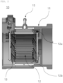
FIG. 1 illustrates a generalhairpin winding motor 10, andFIG. 2 is a cross-sectional view illustrating the generalhairpin winding motor 10. In the illustratedhairpin winding motor 10, a coil winding part of astator core 12 is formed by fasteninghairpin coils 13, which are formed in an approximately 'U' or 'V' shape, into slots of thestator core 12 disposed inside ahousing 11 and then joining and welding thehairpin coils 13 disposed on layers of the slots. Therefore, thehairpin winding motor 10 facilitates the operation of winding the angular coil while overcoming mechanical limitations caused by a winding machine. - Meanwhile, the
housing 11 further includes anoil injection tube 15 through which cooling oil is supplied into thehousing 11 to cool thehairpin winding motor 10 that generates heat. - In the cooling structure for the
hairpin winding motor 10 in the related art, the cooling oil introduced into thehousing 11 flows, as indicated by the arrows, because of rotor plates (not illustrated) disposed at oneopen side 12a and the otheropen side 12b of thestator core 12, and the cooling oil is supplied and circulated only to a radially outer side of thehairpin coil 13, which causes a problem of deterioration in performance in cooling the coil disposed radially inward. - In particular, there is a need to develop a technology to prevent deterioration in performance caused by an increase in temperature of the hairpin coil because the cooling method is biased to the radially outer side even though a large amount of heat is generated from a radially inner side of the hairpin coil adjacent to the rotor.
- The present invention is proposed to solve these problems and aims to provide a hairpin coil cooling structure for a hairpin winding motor, which is capable of improving performance in cooling a radially inner coil, among hairpin coils, adjacent to a rotor that generates the largest amount of heat in the motor.
- The present invention also aims to provide a hairpin coil cooling structure for a hairpin winding motor, which is capable of spraying cooling oil to a rotor plate and rotating the rotor plate so that the cooling oil dispersed by a rotation of the rotor plate is sprayed to an inner coil.
- An embodiment of the present invention provides a hairpin coil cooling structure for a hairpin winding motor including a stator having a plurality of slots formed through the stator in a circumferential direction thereof and each having a plurality of layers in a radial direction thereof, and a plurality of hairpin coils fastened to the slots and connected to one another to define a coil winding, in which the winding motor includes: a rotor rotatably mounted inside the stator; a rotor shaft connected to the rotor; a pair of rotor plates respectively provided at a first end portion and a second end portion of the rotor shaft and configured to cover a first open side and a second open side of the stator; and an oil injection tube configured to spray a cooling oil into the winding motor, in which a nozzle, which is provided at an end of the cooling oil injection tube to spray the cooling oil to an outer surface of the rotor plate, is disposed to be directed toward the outer surface of the rotor plate, and in which the cooling oil sprayed to the outer surface of the rotor plate is scattered toward an inner coil, which is positioned at a radially inner side of the stator among the hairpin coils, by a rotation of the rotor plate.
- In addition, the rotor plate may include: a circular body portion having a center penetrated by the rotor shaft; a spray portion protruding outward from an outer surface of the circular body portion, formed at a radially center of the circular body portion, and formed in a circumferential direction thereof; a spray groove formed in a radially inner surface of the spray portion and recessed radially outward; and a spray hole formed in the spray groove and formed through the radially inner surface and an outer surface of the spray portion, a spray surface configured to spray the cooling oil may be formed on the outer surface of the circular body portion, and the spray surface may be formed at a radially inner side of the spray portion.
- In addition, the cooling oil injection tube may further include an auxiliary nozzle formed on the cooling oil injection tube and directed toward the inner coil to spray the supplied cooling oil directly to the inner coil.
- In addition, the rotor plate may include: a circular body portion having a center penetrated by the rotor shaft; a spray portion protruding outward from an outer surface of the circular body portion, formed at a radially center of the circular body portion, and formed in a circumferential direction thereof; a first spray groove formed in a radially inner surface of the spray portion, disposed adjacent to the outer surface of the circular body portion, and recessed radially outward; a second spray groove formed in the radially inner surface of the spray portion, disposed to be spaced apart from the outer surface of the circular body portion, and recessed radially outward; a spray hole formed in the second spray groove and formed through the radially inner surface and an outer surface of the spray portion; a partition wall formed to separate the first spray groove and the second spray groove; and connection grooves formed in the partition wall so that the cooling oil distributed in the first spray groove moves to the second spray groove, a spray surface configured to spray the cooling oil may be formed on the outer surface of the circular body portion, and the spray surface may be formed at a radially inner side of the spray portion.
- In addition, the connection grooves may be formed at predetermined distances in the circumferential direction and recessed radially inward, the connection groove may be formed adjacent to the spray hole, and a depth of the connection groove may be smaller than a depth of each of the first and second spray grooves.
- In addition, the spray hole may be disposed to be spaced apart from a position, at which the connection groove is formed, by a first angle θ in a direction opposite to the rotation of the rotor plate.
- In addition, the connection groove may be inclined at a second angle a with respect to a rotation axis of the rotor plate in a rotation direction of the rotor plate.
- In addition, the cooling oil injection tube may be connected to a lubricating oil spray tube configured to inject lubricating oil into the winding motor, and the cooling oil may be the lubricating oil.
- In addition, the spray hole may be provided as a plurality of spray holes disposed to be spaced apart from one another in the circumferential direction of the spray portion.
- Further, the auxiliary nozzle may be provided as a plurality of auxiliary nozzles disposed to be spaced apart from one another in a longitudinal direction of the cooling oil injection tube.
-
-
FIG. 1 is a perspective view of a general hairpin winding motor. -
FIG. 2 is a cross-sectional view of the general hairpin winding motor. -
FIG. 3 is a front perspective view of a hairpin winding motor according to an embodiment of the present invention. -
FIG. 4 is a rear perspective view of the hairpin winding motor according to the embodiment of the present invention. -
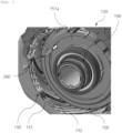
FIG. 5 is a partially enlarged perspective view of the hairpin winding motor according to the embodiment of the present invention. -
FIG. 6 is a perspective view and a cross-sectional inner side view of a rotor plate according to a first embodiment of the present invention. -
FIG. 7 is a partially enlarged perspective view of a hairpin winding motor according to another embodiment of the present invention. -
FIG. 8 is a perspective view illustrating an oil injection tube according to another embodiment of the present invention. -
FIG. 9 is a perspective view and a cross-sectional inner side view of a rotor plate according to a second embodiment of the present invention. -
FIG. 10 is a partially enlarged perspective view illustrating an oil flow path of the rotor plate according to the second embodiment of the present invention. -
FIG. 11 is a partially enlarged front view of a rotor plate according to a third embodiment of the present invention. -
FIG. 12 is a partially enlarged perspective view of a rotor plate according to a fourth embodiment of the present invention. -
FIG. 13 is a partially enlarged perspective view of a hairpin winding motor according to a fifth embodiment of the present invention. -
FIG. 14 is a view illustrating performance in cooling the hairpin winding motor according to the embodiment of the present invention. - Hereinafter, the embodiments of the present invention will be described in detail with reference to the drawings.
-
FIG. 3 is a front perspective view of ahairpin winding motor 100 according to an embodiment of the present invention, andFIG. 4 is a rear perspective view of thehairpin winding motor 100 according to the embodiment of the present invention. - In the illustrated
hairpin winding motor 100, a coil winding part of astator 120 is formed by fasteninghairpin coils 130, which are formed in an approximately 'U' or 'V' shape, into slots of thestator 120 and then joining and welding thehairpin coils 130 disposed on layers of the slots. - Meanwhile, a rotor (not illustrated) is rotatably mounted inside the
stator 120. Arotor shaft 190 is connected to the rotor. Arotor plate 150 is provided at one end of therotor shaft 190 and covers one open side of thestator 120. A rotor plate 150-1 is provided at the other end of therotor shaft 190 and covers the other open side of thestator 120. - In this case, the present invention is characterized in that a part of oil introduced into the
hairpin winding motor 100 is scattered toward a radially inner side of thehairpin coil 130 by therotor plate 150 that rotates in conjunction with therotor shaft 190. A detailed configuration of thehairpin winding motor 100 for implementing the above-mentioned characteristics will be described in detail with reference to the drawings. -
FIG. 5 is a partially enlarged perspective view of thehairpin winding motor 100 according to the embodiment of the present invention. - As illustrated in
FIG. 5 , therotor plate 150 is provided at one open side of thestator 120 and coupled to therotor shaft 190. In addition, thewinding motor 100 includes anoil injection tube 160 configured to supply cooling oil into the windingmotor 100. The coolingoil injection tube 160 has a nozzle formed at an end thereof to supply (spray) the cooling oil to onesurface 151a of therotor plate 150, and the nozzle is disposed to be directed toward one surface of therotor plate 150. - In this case, the following configuration is provided to supply the oil, which is supplied to one
surface 151a of therotor plate 150, to aninner coil 132 positioned at a radially inner side among thehairpin coils 130. -
FIG. 6 is a perspective view and a cross-sectional inner side view of therotor plate 150 according to a first embodiment of the present invention. - As illustrated, the
rotor plate 150 includes a circular plate-shaped body portion 151 having a hollow portion formed at a center thereof so that the rotor shaft penetrates thecircular body portion 151, and aspray portion 152 protruding from one surface of thecircular body portion 151 toward one side. Thespray portion 152 is formed on a radially central portion of thecircular body portion 151 and formed in a circumferential direction. Aspray groove 153 is formed in a radially inner surface of thespray portion 152 and recessed radially outward, and thespray groove 153 is also formed in the circumferential direction. In addition,spray holes 155 are formed in thespray groove 153 and formed through the radially inner surface and an outer surface of thespray portion 152. Thespray holes 155 may be provided as a plurality ofspray holes 155 disposed to be spaced apart from one another in the circumferential direction. - Meanwhile, a
spray surface 151a is formed on one surface of thecircular body portion 151, and thespray surface 151a may be formed at a radially inner side of thespray portion 152. Therefore, when therotor plate 150 rotates, the cooling oil supplied to thespray surface 151a through the coolingoil injection tube 160 is distributed in the circumferential direction on thespray groove 153 of thespray portion 152 by a centrifugal force, and the cooling oil is sprayed in the circumferential direction toward a radially outer side of thespray portion 152 through the spray holes 155. Meanwhile, because theinner coils 132 positioned at the radially inner side among the hairpin coils 130 are disposed adjacent to the outer side of therotor plate 150, the sprayed oil may be scattered toward theinner coils 132. -
FIG. 7 is a partially enlarged perspective view of the hairpin winding motor having anoil injection tube 260 according to another embodiment of the present invention. In addition,FIG. 8 is a perspective view illustrating the coolingoil injection tube 260 according to another embodiment of the present invention. - The
rotor plate 150 is provided at one open side of thestator 120 and coupled to therotor shaft 190. In addition, the windingmotor 100 includes the coolingoil injection tube 260 configured to supply cooling oil into the windingmotor 100. The coolingoil injection tube 260 has a nozzle formed at an end thereof to supply (spray) the cooling oil to onesurface 151a of therotor plate 150, and the nozzle is disposed to be directed toward one surface of therotor plate 150. In this case, the coolingoil injection tube 260 according to another embodiment of the present invention has the following configuration to spray the supplied cooling oil directly to theinner coil 132 positioned at the radially inner side among the hairpin coils 130. -
Auxiliary nozzles 265 may be further provided on the coolingoil injection tube 260, and theauxiliary nozzles 265 are disposed toward theinner coil 132 positioned at the radially inner side among the hairpin coils 130. In addition, theauxiliary nozzles 265 may be provided as a plurality ofauxiliary nozzles 265 disposed to be spaced apart from one another in a longitudinal direction of the coolingoil injection tube 260. Therefore, in the present embodiment, the cooling oil may be scattered toward theinner coil 132 by therotor plate 150, and at the same time, the cooling oil may be sprayed directly to theinner coil 132 through theauxiliary nozzles 265, thereby increasing an area of the cooling oil sprayed to theinner coil 132. -
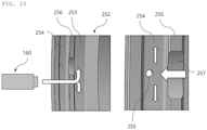
FIG. 9 is a perspective view and a cross-sectional inner side view of arotor plate 250 according to a second embodiment of the present invention, andFIG. 10 is a partially enlarged perspective view illustrating an oil flow path of therotor plate 250 according to the second embodiment of the present invention. - As illustrated, the
rotor plate 250 includes a circular plate-shapedbody portion 251 having a hollow portion formed at a center thereof so that the rotor shaft penetrates thecircular body portion 251, and aspray portion 252 protruding from one surface of thecircular body portion 151 toward one side. Thespray portion 252 is formed on a radially central portion of thecircular body portion 251 and formed in the circumferential direction. First andsecond spray grooves spray portion 252 and recessed radially outward, and the first andsecond spray grooves first spray groove 253 is disposed adjacent to onesurface 251a of thecircular body portion 251, and thesecond spray groove 254 is disposed to be spaced apart from onesurface 251a. Thefirst spray groove 253 and thesecond spray groove 254 are separated by apartition wall 256. In addition, spray holes 255 are formed in thesecond spray groove 254 and formed through the radially inner surface and an outer surface of thespray portion 252. The spray holes 255 may be provided as a plurality ofspray holes 255 disposed to be spaced apart from one another in the circumferential direction. - Meanwhile, a
spray surface 251a is formed on one surface of thecircular body portion 251, and thespray surface 251a may be formed at a radially inner side of thespray portion 252. Therefore, when therotor plate 250 rotates, the cooling oil supplied to thespray surface 251a through the coolingoil injection tube 160 is distributed in the circumferential direction on thefirst spray groove 253 of thespray portion 152 by a centrifugal force. In this case,connection grooves 257 may be formed in thepartition wall 256 so that the cooling oil may move to thesecond spray groove 254 when the cooling oil distributed in thefirst spray groove 253 reaches a predetermined level. Theconnection grooves 257 may be formed at predetermined distances in the circumferential direction and recessed radially inward. A position of theconnection groove 257 may be adjacent to thespray hole 255. In addition, a depth of theconnection groove 257 may be smaller than a depth of each of the first andsecond spray grooves first spray groove 253 reaches a predetermined level, i.e., becomes higher than theconnection groove 257, the cooling oil moves to thesecond spray groove 254 through theconnection groove 257, and the cooling oil supplied to thesecond spray groove 254 is sprayed to theinner coil 132 through thespray hole 255. According to therotor plate 250 of the second embodiment, in a state in which the cooling oil is distributed uniformly in the circumferential direction of thefirst spray groove 253, the cooling oil may be moved to thesecond spray groove 254 through theconnection grooves 257 and sprayed through the spray holes 255, such that the cooling oil may be uniformly distributed to the plurality ofspray holes 255, thereby further improving efficiency in scattering the oil. -
FIG. 11 is a partially enlarged front view of arotor plate 250 according to a third embodiment of the present invention. As illustrated, thespray hole 255 may be disposed to be spaced apart from the position, at which theconnection groove 257 is formed, by a first angle θ in a direction opposite to the rotation of therotor plate 250. - This is based on the fact that the oil, which accumulates in the
first spray groove 253, spirally flows by the rotation of therotor plate 250 when the cooling oil moves to thesecond spray groove 254 through theconnection groove 257. Therefore, theconnection groove 257 and thespray hole 255 may be disposed to be spaced apart from each other by the first angle without being positioned on a straight line in the radial direction. Therefore, the oil, which has moved to thesecond spray groove 254 through theconnection groove 257, may move to thespray hole 255 along the shortest route. -
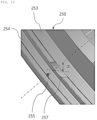
FIG. 12 is a partially enlarged perspective view of arotor plate 250 according to a fourth embodiment of the present invention. - The
connection groove 257 may be inclined at a second angle a with respect to a rotation axis of therotor plate 250 in consideration of the rotation direction of therotor plate 250. That is, in consideration of the situation in which the cooling oil spirally flows by the rotation of therotor plate 250, theconnection groove 257 may be formed to correspond to the spiral flow of the oil, thereby improving the flow performance of the oil. -
FIG. 13 is a partially enlarged perspective view of ahairpin winding motor 100 according to still another embodiment of the present invention. - An
oil injection tube 360 may be connected to a lubricatingoil spray tube 500 configured to supply lubricating oil for lubricating a rotor bearing, and the coolingoil injection tube 360 may be configured to spray the lubricating oil to thespray surface 151a of therotor plate 150. In case that the coolingoil injection tube 360 is connected to a separate tube to directly spray the oil, a load of a pump may be increased by a pressure drop. Therefore, the coolingoil injection tube 360 may be connected to the lubricatingoil spray tube 500 for lubricating the rotor bearing, thereby reducing a pressure drop. -
FIG. 14 is a view illustrating performance in cooling thehairpin winding motor 100 according to the embodiment of the present invention. The light color indicates a high temperature, and the deep color indicates a low temperature. As illustrated, it can be seen that in the case of the windingmotor 100 of the present invention, the cooling oil is sprayed to the inner coil through the spray holes formed in therotor plate 150, and the cooling oil is sprayed uniformly to the inner coil by the rotation of therotor plate 150. - In addition, it can be seen that it is possible to more effectively cool the inner coil, among the hairpin coils, by means of various embodiments such as the sizes of the spray holes, the number of spray grooves, and the like.
- According to the hairpin coil cooling structure for a hairpin winding motor of the present invention configured as described above, the performance in cooling the relatively weak inner coil of the hairpin core may be improved, thereby preventing the deterioration in performance of the hairpin winding motor and improving the durability.
- In addition, the basic configuration of the hairpin winding motor may be maintained, such that the hairpin coil cooling structure may be applied to a motor in the related art, thereby reducing production costs or time, which may be increased by a change in production facilities, and recycling resources.
- The cooling oil scattering flow rate or the cooling oil scattering shape may be easily changed only by changing the shape of the rotor plate, thereby reducing production costs or time that may be increased by a change in layouts of the motor.
- The technical spirit should not be construed as being limited to the embodiments of the present invention. Of course, the scope of application is diverse, and various modifications and implementations may be made by those skilled in the art without departing from the subject matter of the present invention claimed in the claims. Accordingly, these improvements and modifications will fall within the scope of the present invention as long as they are apparent to those skilled in the art.
-
- 100: Hairpin winding motor
- 120: Stator
- 130: Hairpin coil
- 131: Hairpin outer coil
- 132: Hairpin inner coil
- 150, 150-1: Rotor plate
- 151a: Spray surface
- 151: Body portion
- 152: Spray portion
- 153: Spray groove
- 155: Spray hole
- 160, 260: Oil injection tube
- 265: Auxiliary nozzle
- 190: Rotor shaft
- 250: Rotor plate
- 251: Body portion
- 252: Spray portion
- 251a: Spray surface
- 253: First spray groove
- 254: Second spray groove
- 255: Spray hole
- 256: Partition wall
- 257: Connection groove
- 500: Lubricating oil spray tube
Claims (15)
- A hairpin winding motor comprising:A stator having a plurality of slots formed through the stator in a circumferential direction thereof and each having a plurality of layers in a radial direction thereof;a plurality of hairpin coils fastened to the slots and connected to one another to define a coil winding,a rotor rotatably mounted inside the stator;a rotor shaft connected to the rotor;a pair of rotor plates respectively provided at a first end portion and a second end portion of the rotor shaft and configured to cover a first open side and a second open side of the stator; andan oil injection tube configured to spray a cooling oil into the winding motor,wherein a nozzle, which is provided at an end of the cooling oil injection tube to spray the cooling oil to an outer surface of the rotor plate, is disposed to be directed toward the outer surface of the rotor plate, andwherein the cooling oil sprayed to the outer surface of the rotor plate is scattered toward an inner coil, which is positioned at a radially inner side of the stator among the hairpin coils, by a rotation of the rotor plate.
- The hairpin winding motor of claim 1, wherein the rotor plate includes:a circular body portion having a center penetrated by the rotor shaft;a spray portion protruding outward from an outer surface of the circular body portion, formed at a radially center of the circular body portion, and formed in a circumferential direction thereof;a spray groove formed in a radially inner surface of the spray portion and recessed radially outward; anda spray hole formed in the spray groove and formed through the radially inner surface and an outer surface of the spray portion, andwherein a spray surface configured to spray the cooling oil is formed on the outer surface of the circular body portion, and the spray surface is formed at a radially inner side of the spray portion.
- The hairpin winding motor of claim 1 or 2, wherein the cooling oil injection tube further includes an auxiliary nozzle formed on the cooling oil injection tube and directed toward the inner coil to spray the supplied cooling oil directly to the inner coil.
- The hairpin winding motor of any one of claims 1 to 3, wherein the rotor plate includes:a circular body portion having a center penetrated by the rotor shaft;a spray portion protruding outward from an outer surface of the circular body portion, formed at a radially center of the circular body portion, and formed in a circumferential direction thereof;a first spray groove formed in a radially inner surface of the spray portion, disposed adjacent to the outer surface of the circular body portion, and recessed radially outward;a second spray groove formed in the radially inner surface of the spray portion,disposed to be spaced apart from the outer surface of the circular body portion, andrecessed radially outward;a spray hole formed in the second spray groove and formed through the radially inner surface and an outer surface of the spray portion;a partition wall formed to separate the first spray groove and the second spray groove; andconnection grooves formed in the partition wall so that the cooling oil distributed in the first spray groove moves to the second spray groove, andwherein a spray surface configured to spray the cooling oil is formed on the outer surface of the circular body portion, and the spray surface is formed at a radially inner side of the spray portion.
- The hairpin winding motor of claim 4, wherein the connection grooves are formed at predetermined distances in the circumferential direction and recessed radially inward, the connection grooves are formed adjacent to the spray hole, and a depth of the connection grooves is smaller than a depth of each of the first and second spray grooves.
- The hairpin winding motor of claim 4 or 5, wherein the spray hole is disposed to be spaced apart from a position, at which the connection grooves are formed, by a first angle in a direction opposite to the rotation of the rotor plate.
- The hairpin winding motor of any one of claims 4 to 6, wherein the connection grooves are inclined at a second angle with respect to a rotation axis of the rotor plate in a rotation direction of the rotor plate.
- The hairpin winding motor of any one of claims 1 to 7, wherein the cooling oil injection tube is connected to a lubricating oil spray tube configured to inject lubricating oil into the winding motor, and the cooling oil is the lubricating oil.
- The hairpin winding motor of any one of claims 2 to 8, wherein the spray hole is provided as a plurality of spray holes disposed to be spaced apart from one another in the circumferential direction of the spray portion.
- The hairpin winding motor of any one of claims 3 to 9, wherein the auxiliary nozzle is provided as a plurality of auxiliary nozzles disposed to be spaced apart from one another in a longitudinal direction of the cooling oil injection tube.
- A hairpin coil cooling structure for a hairpin winding motor including a stator having a plurality of slots formed through the stator in a circumferential direction thereof and each having a plurality of layers in a radial direction thereof, and a plurality of hairpin coils fastened to the slots and connected to one another to define a coil winding, the hairpin coil cooling structure comprising:an oil injection tube configured to spray a cooling oil into the winding motor, anda nozzle, which is provided at an end of the cooling oil injection tube to spray the cooling oil to an outer surface of the rotor plate, is disposed to be directed toward the outer surface of the rotor plate,wherein the cooling oil sprayed to the outer surface of the rotor plate is scattered toward an inner coil, which is positioned at a radially inner side of the stator among the hairpin coils, by a rotation of the rotor plate.
- The hairpin coil cooling structure of claim 11, further including:a spray portion protruding outward from an outer surface of a circular body portion having a center penetrated by a rotor shaft, formed at a radially center of the circular body portion, and formed in a circumferential direction thereof;a spray groove formed in a radially inner surface of the spray portion and recessed radially outward; anda spray hole formed in the spray groove and formed through the radially inner surface and an outer surface of the spray portion, andwherein a spray surface configured to spray the cooling oil is formed on the outer surface of the circular body portion, and the spray surface is formed at a radially inner side of the spray portion.
- The hairpin coil cooling structure of claim 11 or 12, wherein the cooling oil injection tube further includes an auxiliary nozzle formed on the cooling oil injection tube and directed toward the inner coil to spray the supplied cooling oil directly to the inner coil.
- The hairpin coil cooling structure of any one of claims 11 to 13, further including:a spray portion protruding outward from an outer surface ofa circular body portion having a center penetrated by a rotor shaft, formed at a radially center of the circular body portion, and formed in a circumferential direction thereof;a first spray groove formed in a radially inner surface of the spray portion, disposed adjacent to the outer surface of the circular body portion, and recessed radially outward;a second spray groove formed in the radially inner surface of the spray portion,disposed to be spaced apart from the outer surface of the circular body portion, andrecessed radially outward;a spray hole formed in the second spray groove and formed through the radially inner surface and an outer surface of the spray portion;a partition wall formed to separate the first spray groove and the second spray groove; andconnection grooves formed in the partition wall so that the cooling oil distributed in the first spray groove moves to the second spray groove, andwherein a spray surface configured to spray the cooling oil is formed on the outer surface of the circular body portion, and the spray surface is formed at a radially inner side of the spray portion.
- The hairpin coil cooling structure of claim 14, wherein the connection grooves are formed at predetermined distances in the circumferential direction and recessed radially inward, the connection grooves are formed adjacent to the spray hole, and a depth of the connection grooves is smaller than a depth of each of the first and second spray grooves.
Applications Claiming Priority (1)
| Application Number | Priority Date | Filing Date | Title |
|---|---|---|---|
| KR1020230117930A KR20250035357A (en) | 2023-09-05 | 2023-09-05 | Hairpin coil cooling structure for hairpin winding motor |
Publications (2)
| Publication Number | Publication Date |
|---|---|
| EP4521612A1 true EP4521612A1 (en) | 2025-03-12 |
| EP4521612B1 EP4521612B1 (en) | 2026-04-22 |
Family
ID=91969238
Family Applications (1)
| Application Number | Title | Priority Date | Filing Date |
|---|---|---|---|
| EP24190496.0A Active EP4521612B1 (en) | 2023-09-05 | 2024-07-24 | Hairpin coil cooling structure for hairpin winding motor |
Country Status (4)
| Country | Link |
|---|---|
| US (1) | US20250079918A1 (en) |
| EP (1) | EP4521612B1 (en) |
| KR (1) | KR20250035357A (en) |
| CN (1) | CN223156888U (en) |
Citations (3)
| Publication number | Priority date | Publication date | Assignee | Title |
|---|---|---|---|---|
| US20110298317A1 (en) * | 2010-06-08 | 2011-12-08 | Bradfield Michael D | Electric Machine Cooling System and Method |
| US20220069664A1 (en) * | 2019-01-07 | 2022-03-03 | Lg Magna E-Powertrain Co., Ltd. | Motor |
| FR3116964A1 (en) * | 2020-11-30 | 2022-06-03 | Nidec Psa Emotors | Flange and rotor of rotating electric machine |
-
2023
- 2023-09-05 KR KR1020230117930A patent/KR20250035357A/en active Pending
-
2024
- 2024-07-12 US US18/770,941 patent/US20250079918A1/en active Pending
- 2024-07-24 EP EP24190496.0A patent/EP4521612B1/en active Active
- 2024-09-04 CN CN202422164799.XU patent/CN223156888U/en active Active
Patent Citations (3)
| Publication number | Priority date | Publication date | Assignee | Title |
|---|---|---|---|---|
| US20110298317A1 (en) * | 2010-06-08 | 2011-12-08 | Bradfield Michael D | Electric Machine Cooling System and Method |
| US20220069664A1 (en) * | 2019-01-07 | 2022-03-03 | Lg Magna E-Powertrain Co., Ltd. | Motor |
| FR3116964A1 (en) * | 2020-11-30 | 2022-06-03 | Nidec Psa Emotors | Flange and rotor of rotating electric machine |
Also Published As
| Publication number | Publication date |
|---|---|
| US20250079918A1 (en) | 2025-03-06 |
| EP4521612B1 (en) | 2026-04-22 |
| KR20250035357A (en) | 2025-03-12 |
| CN223156888U (en) | 2025-07-25 |
Similar Documents
| Publication | Publication Date | Title |
|---|---|---|
| US8242645B2 (en) | Rotating electric machine enabling cooling of a cooling target region | |
| EP2724450B1 (en) | Cooling structure of rotary electric machine | |
| JP5772544B2 (en) | Cooling structure of rotating electric machine | |
| CN114503408B (en) | Electric motor with integrated cooling system | |
| KR101738208B1 (en) | Electrical machine cooling system and method | |
| US8456046B2 (en) | Gravity fed oil cooling for an electric machine | |
| CN113273062B (en) | electric motor | |
| US12009703B2 (en) | Rotor-cooling structure of a drive motor | |
| US20150214817A1 (en) | Motor having cooling function | |
| KR102618055B1 (en) | Rotor assembly and motor including the same | |
| US12218550B2 (en) | Electric machine thermal management assembly and method | |
| JP6065805B2 (en) | Electric motor | |
| JP2012223075A (en) | Cooling structure of rotary electric machine | |
| US20240079934A1 (en) | Electric motor comprising a cooling fluid deflector | |
| JP2014030284A (en) | Rotary electric machine for vehicle | |
| JP2014103722A (en) | Rotary electric machine | |
| KR20220082593A (en) | Cooling device of motor | |
| US20250079918A1 (en) | Hairpin coil cooling structure for hairpin winding motor | |
| JP2014090553A (en) | Motor | |
| CN107949978B (en) | Rotary electric machines with optimized cooling | |
| KR20180115898A (en) | Motor for electric vehicles | |
| JP5471383B2 (en) | Motor cooling device | |
| JP2007202243A (en) | Cooling device of automobile motor | |
| JP2010045894A (en) | Rotary electric machine | |
| US20250266736A1 (en) | Cooling mechanism for driving motor |
Legal Events
| Date | Code | Title | Description |
|---|---|---|---|
| PUAI | Public reference made under article 153(3) epc to a published international application that has entered the european phase |
Free format text: ORIGINAL CODE: 0009012 |
|
| STAA | Information on the status of an ep patent application or granted ep patent |
Free format text: STATUS: THE APPLICATION HAS BEEN PUBLISHED |
|
| AK | Designated contracting states |
Kind code of ref document: A1 Designated state(s): AL AT BE BG CH CY CZ DE DK EE ES FI FR GB GR HR HU IE IS IT LI LT LU LV MC ME MK MT NL NO PL PT RO RS SE SI SK SM TR |
|
| STAA | Information on the status of an ep patent application or granted ep patent |
Free format text: STATUS: REQUEST FOR EXAMINATION WAS MADE |
|
| 17P | Request for examination filed |
Effective date: 20250905 |
|
| GRAP | Despatch of communication of intention to grant a patent |
Free format text: ORIGINAL CODE: EPIDOSNIGR1 |
|
| STAA | Information on the status of an ep patent application or granted ep patent |
Free format text: STATUS: GRANT OF PATENT IS INTENDED |
|
| INTG | Intention to grant announced |
Effective date: 20251120 |
|
| GRAS | Grant fee paid |
Free format text: ORIGINAL CODE: EPIDOSNIGR3 |
|
| GRAA | (expected) grant |
Free format text: ORIGINAL CODE: 0009210 |
|
| STAA | Information on the status of an ep patent application or granted ep patent |
Free format text: STATUS: THE PATENT HAS BEEN GRANTED |
|
| P01 | Opt-out of the competence of the unified patent court (upc) registered |
Free format text: CASE NUMBER: UPC_APP_0005433_4521612/2026 Effective date: 20260213 |
|
| AK | Designated contracting states |
Kind code of ref document: B1 Designated state(s): AL AT BE BG CH CY CZ DE DK EE ES FI FR GB GR HR HU IE IS IT LI LT LU LV MC ME MK MT NL NO PL PT RO RS SE SI SK SM TR |
|
| REG | Reference to a national code |
Ref country code: CH Ref legal event code: F10 Free format text: ST27 STATUS EVENT CODE: U-0-0-F10-F00 (AS PROVIDED BY THE NATIONAL OFFICE) Effective date: 20260422 Ref country code: GB Ref legal event code: FG4D |
|
| REG | Reference to a national code |
Ref country code: DE Ref legal event code: R096 Ref document number: 602024004131 Country of ref document: DE |
|
| REG | Reference to a national code |
Ref country code: IE Ref legal event code: FG4D |