EP4521576A2 - Sustained undervoltage protection - Google Patents
Sustained undervoltage protection Download PDFInfo
- Publication number
- EP4521576A2 EP4521576A2 EP24199049.8A EP24199049A EP4521576A2 EP 4521576 A2 EP4521576 A2 EP 4521576A2 EP 24199049 A EP24199049 A EP 24199049A EP 4521576 A2 EP4521576 A2 EP 4521576A2
- Authority
- EP
- European Patent Office
- Prior art keywords
- protection
- undervoltage
- controller
- recited
- generator
- Prior art date
- Legal status (The legal status is an assumption and is not a legal conclusion. Google has not performed a legal analysis and makes no representation as to the accuracy of the status listed.)
- Pending
Links
Images

Classifications
-
- H—ELECTRICITY
- H02—GENERATION; CONVERSION OR DISTRIBUTION OF ELECTRIC POWER
- H02H—EMERGENCY PROTECTIVE CIRCUIT ARRANGEMENTS
- H02H7/00—Emergency protective circuit arrangements specially adapted for specific types of electric machines or apparatus or for sectionalised protection of cable or line systems, and effecting automatic switching in the event of an undesired change from normal working conditions
- H02H7/06—Emergency protective circuit arrangements specially adapted for specific types of electric machines or apparatus or for sectionalised protection of cable or line systems, and effecting automatic switching in the event of an undesired change from normal working conditions for dynamo-electric generators; for synchronous capacitors
-
- H—ELECTRICITY
- H02—GENERATION; CONVERSION OR DISTRIBUTION OF ELECTRIC POWER
- H02P—CONTROL OR REGULATION OF ELECTRIC MOTORS, ELECTRIC GENERATORS OR DYNAMO-ELECTRIC CONVERTERS; CONTROLLING TRANSFORMERS, REACTORS OR CHOKE COILS
- H02P9/00—Arrangements for controlling electric generators for the purpose of obtaining a desired output
- H02P9/006—Means for protecting the generator by using control
-
- H—ELECTRICITY
- H02—GENERATION; CONVERSION OR DISTRIBUTION OF ELECTRIC POWER
- H02H—EMERGENCY PROTECTIVE CIRCUIT ARRANGEMENTS
- H02H3/00—Emergency protective circuit arrangements for automatic disconnection directly responsive to an undesired change from normal electric working condition with or without subsequent reconnection ; integrated protection
- H02H3/24—Emergency protective circuit arrangements for automatic disconnection directly responsive to an undesired change from normal electric working condition with or without subsequent reconnection ; integrated protection responsive to undervoltage or no-voltage
-
- H—ELECTRICITY
- H02—GENERATION; CONVERSION OR DISTRIBUTION OF ELECTRIC POWER
- H02P—CONTROL OR REGULATION OF ELECTRIC MOTORS, ELECTRIC GENERATORS OR DYNAMO-ELECTRIC CONVERTERS; CONTROLLING TRANSFORMERS, REACTORS OR CHOKE COILS
- H02P25/00—Arrangements or methods for the control of AC motors characterised by the kind of AC motor or by structural details
- H02P25/02—Arrangements or methods for the control of AC motors characterised by the kind of AC motor or by structural details characterised by the kind of motor
- H02P25/022—Synchronous motors
- H02P25/024—Synchronous motors controlled by supply frequency
-
- H—ELECTRICITY
- H02—GENERATION; CONVERSION OR DISTRIBUTION OF ELECTRIC POWER
- H02P—CONTROL OR REGULATION OF ELECTRIC MOTORS, ELECTRIC GENERATORS OR DYNAMO-ELECTRIC CONVERTERS; CONTROLLING TRANSFORMERS, REACTORS OR CHOKE COILS
- H02P9/00—Arrangements for controlling electric generators for the purpose of obtaining a desired output
- H02P9/48—Arrangements for obtaining a constant output value at varying speed of the generator, e.g. on vehicle
-
- H—ELECTRICITY
- H02—GENERATION; CONVERSION OR DISTRIBUTION OF ELECTRIC POWER
- H02H—EMERGENCY PROTECTIVE CIRCUIT ARRANGEMENTS
- H02H1/00—Details of emergency protective circuit arrangements
- H02H1/04—Arrangements for preventing response to transient abnormal conditions, e.g. to lightning or to short duration over voltage or oscillations; Damping the influence of DC component by short circuits in AC networks
-
- H—ELECTRICITY
- H02—GENERATION; CONVERSION OR DISTRIBUTION OF ELECTRIC POWER
- H02H—EMERGENCY PROTECTIVE CIRCUIT ARRANGEMENTS
- H02H3/00—Emergency protective circuit arrangements for automatic disconnection directly responsive to an undesired change from normal electric working condition with or without subsequent reconnection ; integrated protection
- H02H3/24—Emergency protective circuit arrangements for automatic disconnection directly responsive to an undesired change from normal electric working condition with or without subsequent reconnection ; integrated protection responsive to undervoltage or no-voltage
- H02H3/247—Emergency protective circuit arrangements for automatic disconnection directly responsive to an undesired change from normal electric working condition with or without subsequent reconnection ; integrated protection responsive to undervoltage or no-voltage having timing means
Definitions
- the present disclosure relates to power quality control for electrical power systems, and more particularly to undervoltage protection for aerospace applications.
- a generator control unit provides a voltage regulation function via closed loop control. If a failure occurs within the GCU or the generator, the regulated voltage at the point of regulation (POR) can be impacted in such a way that it falls out of specified limits.
- POR point of regulation
- an undervoltage (UV) protection is provided within the GCU that compares a measured POR voltage to a predetermined level and time delay. If the voltage remains below this predetermined threshold longer than the specified time delay, then the GCU actuates a protection that removes excitation to the generator and opens the main line contactor. This style of protection expects the voltage remains below a threshold for the entire time delay for it to actuate.
- a method includes detecting a modulating undervoltage state having transients above an undervoltage threshold and triggering a protection upon detecting the modulating undervoltage state.
- the method can include detecting a steady state undervoltage condition.
- Triggering a protection can include triggering the protection upon detecting the steady state undervoltage condition or the modulating undervoltage state.
- Triggering the protection can include removing a generator output from an electrical system by at least one of opening a generator control unit (GCU) generator control relay, removing generator excitation, and/or opening a main line contactor.
- the protection function can include deployment of a ram air turbine (RAT) by an emergency controller.
- RAT ram air turbine
- Detecting the modulating undervoltage state can include receiving feedback from a POR (point of regulation) in a generator system as voltage input, comparing the voltage input against a predetermined set threshold, and setting a latch if the input voltage falls below the predetermined set threshold.
- the method can include resetting the latch only if the input voltage rises above a reset voltage and remains above that level for time delay.
- the latch can be a first latch and the method can include setting a second latch if the input voltage does not recover above the reset threshold for a second time delay, wherein the second latch being set triggers the protection.
- the method can include resetting the first latch if the input voltage falls below a normal limit due to a normal action.
- Resetting the first latch can include using a second voltage threshold to determine if a generator in the generator system is offline, and resetting the first latch if the input voltage is below the second voltage threshold for a third time delay.
- the first and third time delays can each be shorter in duration than the second time delay to prevent nuisance trip conditions.
- a system includes a power source including a feedback sensor at a point of regulation (POR) of the power source configured to generate feedback indicative of voltage at the POR.
- a controller is operatively connected to receive the feedback.
- the controller includes controller logic that is configured perform a method as described above.
- the controller can be configured to detect a steady state undervoltage condition. Triggering a protection can include triggering the protection upon detecting the steady state undervoltage condition or the modulating undervoltage state.
- the power source can include a generator with an output connected to supply power to an electrical system, wherein triggering the protection includes removing the generator output from the electrical system by at least one of opening a generator control unit (GCU) generator control relay, removing generator excitation, and/or opening a main line contactor.
- GCU generator control unit
- a ram air turbine (RAT) can be operatively connected to supply the electrical system as a backup to the power source, wherein the protection includes deployment of the RAT by an emergency controller.
- the controller logic can be implemented in analog circuitry, a microprocessor/DSP (digital signal processor), or FPGA (field programmable gate array).
- the controller can include multiple processors, wherein the detecting and triggering are implemented in a redundant process across different processors to provide backup processes of protection.
- the controller logic can be implemented in analog circuitry as a primary or redundant protection either within the controller or external to the controller.
- the power source can be a high voltage direct current (HVDC) power source, and the electrical system can be an HVDC electrical system.
- a VSCF (variable speed constant frequency) regulator can connect between the power source and the electrical system.
- the controller can be configured to trigger the protection based on voltage feedback from multiple phases that track each other.
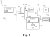
- Fig. 1 a partial view of an embodiment of a system in accordance with the disclosure is shown in Fig. 1 and is designated generally by reference character 100.
- Fig. 2 Other embodiments of systems in accordance with the disclosure, or aspects thereof, are provided in Fig. 2 , as will be described.
- the systems and methods described herein can be used to provide undervoltage protection for steady state undervoltage as well as for modulating undervoltage, e.g. for use in aerospace applications.
- the system 100 includes a power source 102, e.g.
- a synchronous generator including a feedback sensor 104 at a point of regulation (POR) of the power source configured to generate feedback 106 indicative of voltage at the POR.
- a controller 108 which can be a generator control unit (GCU) 110, can be connected to the GCU 110, or can be a separate module of the GCU 110, is operatively connected to receive the feedback 106.
- the controller 108 includes controller logic that is configured perform a method such as described below.
- control lines 106, 128, 130, and the line from the relay 116 can be wired lines, optical lines, wireless lines, or any other suitable lines of communicating feedback and control signals.
- the controller 108 is configured to trigger the protection based on voltage feedback from multiple phases that track each other.
- the method described below with reference to Fig. 2 could be applied to VSCF regulators with minor modifications, namely in a VSCF application the OR gate 136 for VRESET would need to be converted to and AND gate.
- the method includes detecting a modulating undervoltage state, e.g. with the sensor 104 at the POR, having transients above an undervoltage threshold and triggering a protection upon detecting the modulating undervoltage state.
- the method can also include detecting a steady state undervoltage condition, and triggering the protection upon detecting the steady state undervoltage condition or the modulating undervoltage state.
- triggering the protection can include removing a generator output from an electrical system by at least one of opening a generator control unit (GCU) generator control relay, removing generator excitation, opening a main line contactor.
- GCU generator control unit
- Detecting the modulating undervoltage state includes receiving feedback 138 from a POR in a generator system as voltage input, comparing the voltage input against a predetermined set threshold (VSET) 140, and setting a latch 142 (which can be implemented as software or hardware) if the input voltage 138 (in all sense phases via the AND gate 161) falls below the predetermined set threshold VSET 140.
- the set or latched condition of the first latch 142 is denoted as AC_BUS_LOSS_COND in Fig. 2 .
- the voltage input 138 is shown as three phase (V_SENSE_A, V_SENSE_B, V_SENSE_C) but it could be single phase or any number of phases.
- the method includes resetting the latch 142, reseting the AC_BUS_LOSS_COND condition, only if the input voltage 138 of one of the sensed phases rises above a predetermined hysteresis reset voltage (VRESET) 144 and remains above that level for time delay (TD1) 146.
- VRESET hysteresis reset voltage
- the OR gate 136 can be changed to an AND gate as explained above, it the power source is a VSCF power source, so that if all of the input voltages 138 rise above VRESET 144 for TD1 146, then the latch 142 can be reset. Either way, the gate 136 is able to reset the latch 142 by way of the OR gate 148.
- the method includes setting a second latch (PROTECTION_LATCH) 152 to generate the protection trigger signal (ABNRML_AC_PQ) 154 if the input voltage input 138 does not recover above the reset threshold (VRESET) 144 for a second time delay (TD3) 156.
- the first latch 142 not being reset within the time delay (TD3) 156 sets the protection latch 152.
- the method 200 includes resetting the first latch 142 if the input voltage 138 falls below a normal limit due to a normal action.
- This normal action can include power down, i.e. a powering down under normal conditions as when an aircraft powers down after a flight.
- This reset allows the first latch 142 to reset when power cycles, e.g. for each new flight of an aircraft.
- Resetting the power quality (PQ) condition of the first latch 142 includes using a second voltage threshold (VRESETI) 160 to determine if a generator in the generator system is offline, and resetting the first latch 142 if all sensed phases of the input voltage 138, via the AND gate 162 are below the second voltage threshold (VRESETI) 160 for a third time delay (TD2) 164.
- the output of the AND gate 162 is connected to the OR gate 148, as one of the resets for the latch 142.
- the first and third time delays (TD1) 146 and (TD2) 164 are each shorter in duration than the second time delay (TD3) 156 to prevent nuisance trip conditions.
- Systems and methods as disclosed herein provide potential benefits including the following. They can provide an ability to detect failures that lead to modulating voltage.
Landscapes
- Engineering & Computer Science (AREA)
- Power Engineering (AREA)
- Emergency Protection Circuit Devices (AREA)
- Protection Of Generators And Motors (AREA)
- Control Of Eletrric Generators (AREA)
Abstract
Description
- The present disclosure relates to power quality control for electrical power systems, and more particularly to undervoltage protection for aerospace applications.
- In systems using a synchronous generator, a generator control unit (GCU) provides a voltage regulation function via closed loop control. If a failure occurs within the GCU or the generator, the regulated voltage at the point of regulation (POR) can be impacted in such a way that it falls out of specified limits. Traditionally, an undervoltage (UV) protection is provided within the GCU that compares a measured POR voltage to a predetermined level and time delay. If the voltage remains below this predetermined threshold longer than the specified time delay, then the GCU actuates a protection that removes excitation to the generator and opens the main line contactor. This style of protection expects the voltage remains below a threshold for the entire time delay for it to actuate. However, there are failure cases where the GCU regulation function can have a failure that causes the POR voltage to modulate above and below the traditional UV protection thresholds. If this modulation occurs continuously it can drive the power quality to the loads serviced by the generator outside predetermined power quality limits. The conventional techniques have been considered satisfactory for their intended purpose. However, there is an ever present need for improved systems and methods for determining when these modulating undervoltage cases are occurring and providing the appropriate UV protection functions. This disclosure provides a solution for this need.
- A method includes detecting a modulating undervoltage state having transients above an undervoltage threshold and triggering a protection upon detecting the modulating undervoltage state.
- The method can include detecting a steady state undervoltage condition. Triggering a protection can include triggering the protection upon detecting the steady state undervoltage condition or the modulating undervoltage state. Triggering the protection can include removing a generator output from an electrical system by at least one of opening a generator control unit (GCU) generator control relay, removing generator excitation, and/or opening a main line contactor. The protection function can include deployment of a ram air turbine (RAT) by an emergency controller.
- Detecting the modulating undervoltage state can include receiving feedback from a POR (point of regulation) in a generator system as voltage input, comparing the voltage input against a predetermined set threshold, and setting a latch if the input voltage falls below the predetermined set threshold. The method can include resetting the latch only if the input voltage rises above a reset voltage and remains above that level for time delay.
- The latch can be a first latch and the method can include setting a second latch if the input voltage does not recover above the reset threshold for a second time delay, wherein the second latch being set triggers the protection. The method can include resetting the first latch if the input voltage falls below a normal limit due to a normal action. Resetting the first latch can include using a second voltage threshold to determine if a generator in the generator system is offline, and resetting the first latch if the input voltage is below the second voltage threshold for a third time delay. The first and third time delays can each be shorter in duration than the second time delay to prevent nuisance trip conditions.
- A system includes a power source including a feedback sensor at a point of regulation (POR) of the power source configured to generate feedback indicative of voltage at the POR. A controller is operatively connected to receive the feedback. The controller includes controller logic that is configured perform a method as described above.
- The controller can be configured to detect a steady state undervoltage condition. Triggering a protection can include triggering the protection upon detecting the steady state undervoltage condition or the modulating undervoltage state. The power source can include a generator with an output connected to supply power to an electrical system, wherein triggering the protection includes removing the generator output from the electrical system by at least one of opening a generator control unit (GCU) generator control relay, removing generator excitation, and/or opening a main line contactor. A ram air turbine (RAT) can be operatively connected to supply the electrical system as a backup to the power source, wherein the protection includes deployment of the RAT by an emergency controller.
- The controller logic can be implemented in analog circuitry, a microprocessor/DSP (digital signal processor), or FPGA (field programmable gate array). The controller can include multiple processors, wherein the detecting and triggering are implemented in a redundant process across different processors to provide backup processes of protection. The controller logic can be implemented in analog circuitry as a primary or redundant protection either within the controller or external to the controller.
- The power source can be a high voltage direct current (HVDC) power source, and the electrical system can be an HVDC electrical system. A VSCF (variable speed constant frequency) regulator can connect between the power source and the electrical system. The controller can be configured to trigger the protection based on voltage feedback from multiple phases that track each other.
- These and other features of the systems and methods of the subject disclosure will become more readily apparent to those skilled in the art from the following detailed description of the preferred embodiments taken in conjunction with the drawings.
- So that those skilled in the art to which the subject disclosure appertains will readily understand how to make and use the devices and methods of the subject disclosure without undue experimentation, preferred embodiments thereof will be described in detail herein below with reference to certain figures, wherein:
-
Fig. 1 is a schematic perspective view of an embodiment of a system constructed in accordance with the present disclosure, showing the generator, electrical system powered by the generator, and the controller with the protection functions; and -
Fig. 2 is a logic diagram showing protection functions of the controller ofFig. 1 . - Reference will now be made to the drawings wherein like reference numerals identify similar structural features or aspects of the subj ect disclosure. For purposes of explanation and illustration, and not limitation, a partial view of an embodiment of a system in accordance with the disclosure is shown in
Fig. 1 and is designated generally byreference character 100. Other embodiments of systems in accordance with the disclosure, or aspects thereof, are provided inFig. 2 , as will be described. The systems and methods described herein can be used to provide undervoltage protection for steady state undervoltage as well as for modulating undervoltage, e.g. for use in aerospace applications. Thesystem 100 includes apower source 102, e.g. a synchronous generator, including afeedback sensor 104 at a point of regulation (POR) of the power source configured to generatefeedback 106 indicative of voltage at the POR. Acontroller 108, which can be a generator control unit (GCU) 110, can be connected to theGCU 110, or can be a separate module of theGCU 110, is operatively connected to receive thefeedback 106. Thecontroller 108 includes controller logic that is configured perform a method such as described below. - The
power source 102 has anoutput 112 connected to supply power to anelectrical system 114, e.g. a power bus aboard an aircraft. Triggering the protection can include removing theoutput 112 from theelectrical system 114 by at least one of opening aGCU control relay 116, removing generator excitation in theexciter 118, and/or opening amain line contactor 120 to isolate thepower source 102 from theelectrical system 114. A ram air turbine (RAT) 122 can be operatively connected to supply theelectrical system 114 as a backup to the power source, wherein the protection includes auto deployment of the RAT (by the emergency controller indicated inFig. 1 ) and/or closing anelectrical contactor 124 to connect theRAT 122 to theelectrical system 114, viacontrol lines control lines relay 116, can be wired lines, optical lines, wireless lines, or any other suitable lines of communicating feedback and control signals. - The logic of the
controller 108, for implementing methods as described below, can be implemented in analog circuitry, as a microprocessor/DSP (digital signal processor), or as a, FPGA (field programmable gate array). Thecontroller 108 can includemultiple processors 134, wherein the detecting and triggering are implemented in a redundant process acrossdifferent processors 134 to provide backup processes of protection. The controller logic can be implemented in analog circuitry as a primary or redundant protection either within thesame controller 108 or external to theprimary controller 108. - The
power source 102 can be a high voltage direct current (HVDC) power source, and theelectrical system 114 can be an HVDC electrical system, which can be accomplished via passive or active rectification orpower source 102 output. Thepower source 102 output is rectified byconversion block 132. The POR in this case is a single DC feed. If thesystem 100 includes apower source 102 that is a VSCF (variable speed constant frequency) generator, aconversion block 132 can connect between thepower source 102 and theelectrical system 114 with a line (indicated by a broken line inFig. 1 ) connecting theconversion block 132 for control/feedback to/from theGCU 110. In this case, thecontroller 108 is configured to trigger the protection based on voltage feedback from multiple phases that track each other. The method described below with reference toFig. 2 could be applied to VSCF regulators with minor modifications, namely in a VSCF application theOR gate 136 for VRESET would need to be converted to and AND gate. - With reference now to
Fig. 2 , the logic 200 for the methods of the protection functions of thecontroller 108 ofFig. 1 are described. The method includes detecting a modulating undervoltage state, e.g. with thesensor 104 at the POR, having transients above an undervoltage threshold and triggering a protection upon detecting the modulating undervoltage state. The method can also include detecting a steady state undervoltage condition, and triggering the protection upon detecting the steady state undervoltage condition or the modulating undervoltage state. As explained above with reference toFig. 1 , triggering the protection can include removing a generator output from an electrical system by at least one of opening a generator control unit (GCU) generator control relay, removing generator excitation, opening a main line contactor. - Detecting the modulating undervoltage state includes receiving
feedback 138 from a POR in a generator system as voltage input, comparing the voltage input against a predetermined set threshold (VSET) 140, and setting a latch 142 (which can be implemented as software or hardware) if the input voltage 138 (in all sense phases via the AND gate 161) falls below the predeterminedset threshold VSET 140. The set or latched condition of thefirst latch 142 is denoted as AC_BUS_LOSS_COND inFig. 2 . Thevoltage input 138 is shown as three phase (V_SENSE_A, V_SENSE_B, V_SENSE_C) but it could be single phase or any number of phases. - The method includes resetting the
latch 142, reseting the AC_BUS_LOSS_COND
condition, only if theinput voltage 138 of one of the sensed phases rises above a predetermined hysteresis reset voltage (VRESET) 144 and remains above that level for time delay (TD1) 146. The ORgate 136 can be changed to an AND gate as explained above, it the power source is a VSCF power source, so that if all of theinput voltages 138 rise aboveVRESET 144 forTD1 146, then thelatch 142 can be reset. Either way, thegate 136 is able to reset thelatch 142 by way of the OR gate 148. - The method includes setting a second latch (PROTECTION_LATCH) 152 to generate the protection trigger signal (ABNRML_AC_PQ) 154 if the
input voltage input 138 does not recover above the reset threshold (VRESET) 144 for a second time delay (TD3) 156. Thefirst latch 142 not being reset within the time delay (TD3) 156 sets theprotection latch 152. - With continued reference to
Fig. 2 , the method 200 includes resetting thefirst latch 142 if theinput voltage 138 falls below a normal limit due to a normal action. This normal action can include power down, i.e. a powering down under normal conditions as when an aircraft powers down after a flight. This reset allows thefirst latch 142 to reset when power cycles, e.g. for each new flight of an aircraft. Resetting the power quality (PQ) condition of thefirst latch 142 includes using a second voltage threshold (VRESETI) 160 to determine if a generator in the generator system is offline, and resetting thefirst latch 142 if all sensed phases of theinput voltage 138, via the ANDgate 162 are below the second voltage threshold (VRESETI) 160 for a third time delay (TD2) 164. The output of the ANDgate 162 is connected to the OR gate 148, as one of the resets for thelatch 142. The first and third time delays (TD1) 146 and (TD2) 164 are each shorter in duration than the second time delay (TD3) 156 to prevent nuisance trip conditions. - Systems and methods as disclosed herein provide potential benefits including the following. They can provide an ability to detect failures that lead to modulating voltage.
- Previous protections could easily be reset in these conditions whereas systems and methods as disclosed herein can prevent loads from being subjected to bad power quality continuously. Methods as disclosed herein are modular and can be used in different controllers to provide different outcomes. Systems and methods as disclosed herein can provide for DC conversion protection, RAT deployment, and any other suitable type of protection. Systems and methods as disclosed herein can be applied to other PQ items such as frequency.
- The methods and systems of the present disclosure, as described above and shown in the drawings, provide for undervoltage protection for steady state undervoltage as well as for
modulating undervoltage, e.g. for use in aerospace applications. While the apparatus and methods of the subject disclosure have been shown and described with reference to preferred embodiments, those skilled in the art will readily appreciate that changes and/or modifications may be made thereto without departing from the scope of the subject disclosure.
Claims (15)
- A method comprising:
detecting a modulating undervoltage state having transients above an undervoltage threshold (140); and triggering a protection upon detecting the modulating undervoltage state. - The method as recited in claim 1, further comprising detecting a steady state undervoltage condition, wherein triggering a protection includes triggering the protection upon detecting the steady state undervoltage condition or the modulating undervoltage state; and/or
wherein triggering the protection includes removing a generator output from an electrical system by at least one of opening a generator control unit, GCU (110), generator control relay (116) removing generator excitation (118), and/or opening a main line contactor (120). - The method as recited in claim 1 or 2, wherein detecting the modulating undervoltage state includes:receiving feedback (138) from a point of regulation, POR, in a generator system as voltage input;comparing the voltage input against a predetermined set threshold; andsetting a latch (142) in response to the input voltage (138) falling below the predetermined set threshold.
- The method as recited in claim 3, further comprising resetting the latch only in response to the input voltage rising above a reset voltage and remaining above that level for time delay.
- The method as recited in claim 4, wherein the latch is a first latch (142) and further comprising
setting a second latch (152) in response to the input voltage not recovering above the reset threshold for a second time delay (156), wherein the second latch (152) being set triggers the protection. - The method as recited in claim 5, further comprising resetting the first latch in response to the input voltage falling below a normal limit due to a normal action.
- The method as recited in claim 6, wherein resetting the first latch (142) includes using a second voltage threshold (160) to determine if a generator in the generator system is offline, and resetting the first latch (142) in response to the input voltage (138) being below the second voltage threshold (160) for a third time delay (164), and optionally;
wherein the first (146) and third (164) time delays are each shorter in duration than the second time delay (156) to prevent nuisance trip conditions. - The method as recited in any preceding claim, wherein the protection function includes deployment of a ram air turbine (122) by an emergency controller.
- A system comprising:a power source (102) including a feedback sensor (104) at a point of regulation, POR, of the power source configured to generate feedback (106) indicative of voltage at the POR; anda controller (108) operatively connected to receive the feedback (106), wherein the controller (108) includes controller logic that is configured to: detect a modulating undervoltage state having transients above an undervoltage threshold;trigger a protection upon detecting the modulating undervoltage state
- The system as recited in claim 9, wherein the controller is configured to detect a steady state undervoltage condition, wherein triggering a protection includes triggering the protection upon detecting the steady state undervoltage condition or the modulating undervoltage state; and/or
wherein the power source (102) includes a generator with an output connected to supply power to an electrical system, wherein triggering the protection includes removing the generator output from the electrical system by at least one of opening a generator control unit (110) generator control relay (116), removing generator excitation (118), and/or opening a main line contactor (120). - The system as recited in any of claims 9 or 10, wherein the controller logic is implemented in analog circuitry, a microprocessor/digital signal processor, or field programmable gate array, and/or;
wherein the controller (108) includes multiple processors (134), wherein the detecting and triggering are implemented in a redundant process across different processors to provide backup processes of protection. - The system as recited in any of claims 9 to 11, wherein the controller logic is implemented in analog circuitry as a primary or redundant protection either within the controller or external to the controller, and/or;
further comprising a ram air turbine (122) operatively connected to supply the electrical system as a backup to the power source (102), wherein the protection includes deployment of the RAT by an emergency controller. - The system as recited in any of claims 9 to 12, wherein the power source is a high voltage direct current, power source, and wherein the electrical system is an HVDC electrical system.
- The system as recited in any of claims 9 to 13, further comprising a variable speed constant frequency regulator connecting between the power source (102) and the electrical system (114).
- The system as recited in claim 14, wherein the controller is configured to trigger the protection based on voltage feedback from multiple phases that track each other.
Applications Claiming Priority (1)
| Application Number | Priority Date | Filing Date | Title |
|---|---|---|---|
| US18/242,728 US12549118B2 (en) | 2023-09-06 | 2023-09-06 | Sustained undervoltage protection |
Publications (2)
| Publication Number | Publication Date |
|---|---|
| EP4521576A2 true EP4521576A2 (en) | 2025-03-12 |
| EP4521576A3 EP4521576A3 (en) | 2025-04-16 |
Family
ID=92711145
Family Applications (1)
| Application Number | Title | Priority Date | Filing Date |
|---|---|---|---|
| EP24199049.8A Pending EP4521576A3 (en) | 2023-09-06 | 2024-09-06 | Sustained undervoltage protection |
Country Status (2)
| Country | Link |
|---|---|
| US (1) | US12549118B2 (en) |
| EP (1) | EP4521576A3 (en) |
Family Cites Families (15)
| Publication number | Priority date | Publication date | Assignee | Title |
|---|---|---|---|---|
| US5422778A (en) | 1993-07-28 | 1995-06-06 | Sundstrand Corporation | Protection system for controller and control wiring induced under voltage faults in an electric power generating system |
| US5495381A (en) | 1994-11-22 | 1996-02-27 | Sundstrand Corporation | Protection system for undetected over voltage in an isolated voltage regulator |
| US7633272B2 (en) * | 2007-07-11 | 2009-12-15 | Honeywell International Inc. | Load-off transient acceleration generator control system |
| US8294429B2 (en) | 2009-05-22 | 2012-10-23 | Honeywell International Inc. | Robust digital voltage regulator |
| US8688283B2 (en) | 2010-07-16 | 2014-04-01 | Honeywell International Inc. | Method and system for power quality protection |
| US10000296B2 (en) | 2015-02-18 | 2018-06-19 | Hamilton Sundstrand Corporation | Electrical control system |
| US10199968B2 (en) | 2017-05-22 | 2019-02-05 | Infineon Technologies Ag | Fault handling for alternator control devices |
| CN110676812B (en) | 2018-07-03 | 2023-04-14 | 上海航空电器有限公司 | Current and voltage protection structure of single-channel multi-electric aircraft generator controller |
| FR3091423B1 (en) | 2018-12-28 | 2021-09-10 | Safran Electrical & Power | PROTECTION AGAINST OVERVOLTAGES OF AN ELECTRICAL ENERGY GENERATION SYSTEM AT VARIABLE SPEED AND CONSTANT FREQUENCY |
| US10833616B1 (en) | 2019-11-22 | 2020-11-10 | Rolls-Royce Marine North America Inc. | Gas turbine engine generator power management control system |
| US11736026B2 (en) * | 2020-05-29 | 2023-08-22 | Dialog Semiconductor Inc. | Flyback converter with fast load transient detection |
| US12304325B2 (en) | 2020-08-11 | 2025-05-20 | The Boeing Company | Power system controller failsafe cycling protection |
| DE102020123149A1 (en) * | 2020-09-04 | 2022-03-10 | Infineon Technologies Ag | CONTROL CIRCUIT FOR ELECTRONIC SWITCH |
| CN113054619A (en) | 2021-03-31 | 2021-06-29 | 黄山学院 | High-precision high-reliability undervoltage protection circuit for high-voltage gate driving chip |
| GB202209357D0 (en) * | 2022-06-27 | 2022-08-10 | Rolls Royce Plc | Aircraft power and propulsion systems comprising permanent magnet electrical machines |
-
2023
- 2023-09-06 US US18/242,728 patent/US12549118B2/en active Active
-
2024
- 2024-09-06 EP EP24199049.8A patent/EP4521576A3/en active Pending
Also Published As
| Publication number | Publication date |
|---|---|
| EP4521576A3 (en) | 2025-04-16 |
| US12549118B2 (en) | 2026-02-10 |
| US20250080016A1 (en) | 2025-03-06 |
Similar Documents
| Publication | Publication Date | Title |
|---|---|---|
| JP4053890B2 (en) | Wind turbine operating method | |
| US10305285B2 (en) | Photovoltaic voltage regulation | |
| CN104919671B (en) | For protecting multiple strings of a photovoltaic generator from the method and apparatus of reverse current | |
| JP4846597B2 (en) | DC / DC converter and distributed power generation system including the same | |
| US5422778A (en) | Protection system for controller and control wiring induced under voltage faults in an electric power generating system | |
| EP2595265A1 (en) | Power supply system of a marine vessel | |
| US20040207206A1 (en) | Method for operating a wind energy plant | |
| EP2408079A2 (en) | Method and system for power quality protection | |
| EP2608341A1 (en) | Grounding device | |
| US9509134B2 (en) | Centralized DC curtailment for overvoltage protection | |
| KR101529982B1 (en) | System for satisfying low voltage ride through capability of single phase grid connected pv inverter | |
| US5555151A (en) | No-brake power transfer phase balance sychronization sense circuit and method | |
| US12549118B2 (en) | Sustained undervoltage protection | |
| JP7226560B2 (en) | Renewable energy power plant system and plant controller | |
| US20120106009A1 (en) | Shunt Regulator at Excitation Output of Generator Control Unit for Overvoltage Protection | |
| CN113785466B (en) | Power supply device and control method for power supply device | |
| US11081886B2 (en) | Method for detecting formation of a separate system | |
| CN115275970B (en) | A power supply system and control method | |
| EP3086457B1 (en) | Inverter control device | |
| EP2937965B1 (en) | Detection of islanding state in electricity network | |
| JP7011907B2 (en) | Power supply, power supply control | |
| US20210135448A1 (en) | Power converter monitor and method of use | |
| RU2482598C1 (en) | Method for control of power generation system and device for its realisation | |
| WO2023042408A1 (en) | Microgrid system and method for controlling microgrid system | |
| Andrews | A failure tolerant power subsystem for outer planet spacecraft |
Legal Events
| Date | Code | Title | Description |
|---|---|---|---|
| PUAI | Public reference made under article 153(3) epc to a published international application that has entered the european phase |
Free format text: ORIGINAL CODE: 0009012 |
|
| STAA | Information on the status of an ep patent application or granted ep patent |
Free format text: STATUS: THE APPLICATION HAS BEEN PUBLISHED |
|
| AK | Designated contracting states |
Kind code of ref document: A2 Designated state(s): AL AT BE BG CH CY CZ DE DK EE ES FI FR GB GR HR HU IE IS IT LI LT LU LV MC ME MK MT NL NO PL PT RO RS SE SI SK SM TR |
|
| PUAL | Search report despatched |
Free format text: ORIGINAL CODE: 0009013 |
|
| AK | Designated contracting states |
Kind code of ref document: A3 Designated state(s): AL AT BE BG CH CY CZ DE DK EE ES FI FR GB GR HR HU IE IS IT LI LT LU LV MC ME MK MT NL NO PL PT RO RS SE SI SK SM TR |
|
| RIC1 | Information provided on ipc code assigned before grant |
Ipc: H02H 3/247 20060101ALN20250310BHEP Ipc: H02H 7/06 20060101ALI20250310BHEP Ipc: H02H 1/04 20060101ALI20250310BHEP Ipc: H02H 3/24 20060101AFI20250310BHEP |
|
| STAA | Information on the status of an ep patent application or granted ep patent |
Free format text: STATUS: REQUEST FOR EXAMINATION WAS MADE |
|
| 17P | Request for examination filed |
Effective date: 20251014 |