EP4521562A1 - Photovoltaic connector - Google Patents
Photovoltaic connector Download PDFInfo
- Publication number
- EP4521562A1 EP4521562A1 EP22940784.6A EP22940784A EP4521562A1 EP 4521562 A1 EP4521562 A1 EP 4521562A1 EP 22940784 A EP22940784 A EP 22940784A EP 4521562 A1 EP4521562 A1 EP 4521562A1
- Authority
- EP
- European Patent Office
- Prior art keywords
- plug
- photovoltaic
- socket
- cable
- pin
- Prior art date
- Legal status (The legal status is an assumption and is not a legal conclusion. Google has not performed a legal analysis and makes no representation as to the accuracy of the status listed.)
- Pending
Links
Images









Classifications
-
- H—ELECTRICITY
- H02—GENERATION; CONVERSION OR DISTRIBUTION OF ELECTRIC POWER
- H02S—GENERATION OF ELECTRIC POWER BY CONVERSION OF INFRARED RADIATION, VISIBLE LIGHT OR ULTRAVIOLET LIGHT, e.g. USING PHOTOVOLTAIC [PV] MODULES
- H02S40/00—Components or accessories in combination with PV modules, not provided for in groups H02S10/00 - H02S30/00
- H02S40/30—Electrical components
-
- H—ELECTRICITY
- H01—ELECTRIC ELEMENTS
- H01R—ELECTRICALLY-CONDUCTIVE CONNECTIONS; STRUCTURAL ASSOCIATIONS OF A PLURALITY OF MUTUALLY-INSULATED ELECTRICAL CONNECTING ELEMENTS; COUPLING DEVICES; CURRENT COLLECTORS
- H01R13/00—Details of coupling devices of the kinds covered by groups H01R12/70 or H01R24/00 - H01R33/00
- H01R13/46—Bases; Cases
- H01R13/514—Bases; Cases composed as a modular blocks or assembly, i.e. composed of co-operating parts provided with contact members or holding contact members between them
-
- H—ELECTRICITY
- H01—ELECTRIC ELEMENTS
- H01R—ELECTRICALLY-CONDUCTIVE CONNECTIONS; STRUCTURAL ASSOCIATIONS OF A PLURALITY OF MUTUALLY-INSULATED ELECTRICAL CONNECTING ELEMENTS; COUPLING DEVICES; CURRENT COLLECTORS
- H01R13/00—Details of coupling devices of the kinds covered by groups H01R12/70 or H01R24/00 - H01R33/00
- H01R13/02—Contact members
- H01R13/04—Pins or blades for co-operation with sockets
-
- H—ELECTRICITY
- H01—ELECTRIC ELEMENTS
- H01R—ELECTRICALLY-CONDUCTIVE CONNECTIONS; STRUCTURAL ASSOCIATIONS OF A PLURALITY OF MUTUALLY-INSULATED ELECTRICAL CONNECTING ELEMENTS; COUPLING DEVICES; CURRENT COLLECTORS
- H01R13/00—Details of coupling devices of the kinds covered by groups H01R12/70 or H01R24/00 - H01R33/00
- H01R13/02—Contact members
- H01R13/10—Sockets for co-operation with pins or blades
-
- H—ELECTRICITY
- H01—ELECTRIC ELEMENTS
- H01R—ELECTRICALLY-CONDUCTIVE CONNECTIONS; STRUCTURAL ASSOCIATIONS OF A PLURALITY OF MUTUALLY-INSULATED ELECTRICAL CONNECTING ELEMENTS; COUPLING DEVICES; CURRENT COLLECTORS
- H01R13/00—Details of coupling devices of the kinds covered by groups H01R12/70 or H01R24/00 - H01R33/00
- H01R13/46—Bases; Cases
- H01R13/52—Dustproof, splashproof, drip-proof, waterproof, or flameproof cases
- H01R13/5205—Sealing means between cable and housing, e.g. grommet
-
- H—ELECTRICITY
- H01—ELECTRIC ELEMENTS
- H01R—ELECTRICALLY-CONDUCTIVE CONNECTIONS; STRUCTURAL ASSOCIATIONS OF A PLURALITY OF MUTUALLY-INSULATED ELECTRICAL CONNECTING ELEMENTS; COUPLING DEVICES; CURRENT COLLECTORS
- H01R13/00—Details of coupling devices of the kinds covered by groups H01R12/70 or H01R24/00 - H01R33/00
- H01R13/46—Bases; Cases
- H01R13/52—Dustproof, splashproof, drip-proof, waterproof, or flameproof cases
- H01R13/5219—Sealing means between coupling parts, e.g. interfacial seal
- H01R13/5221—Sealing means between coupling parts, e.g. interfacial seal having cable sealing means
-
- H—ELECTRICITY
- H01—ELECTRIC ELEMENTS
- H01R—ELECTRICALLY-CONDUCTIVE CONNECTIONS; STRUCTURAL ASSOCIATIONS OF A PLURALITY OF MUTUALLY-INSULATED ELECTRICAL CONNECTING ELEMENTS; COUPLING DEVICES; CURRENT COLLECTORS
- H01R13/00—Details of coupling devices of the kinds covered by groups H01R12/70 or H01R24/00 - H01R33/00
- H01R13/73—Means for mounting coupling parts to apparatus or structures, e.g. to a wall
-
- H—ELECTRICITY
- H02—GENERATION; CONVERSION OR DISTRIBUTION OF ELECTRIC POWER
- H02S—GENERATION OF ELECTRIC POWER BY CONVERSION OF INFRARED RADIATION, VISIBLE LIGHT OR ULTRAVIOLET LIGHT, e.g. USING PHOTOVOLTAIC [PV] MODULES
- H02S40/00—Components or accessories in combination with PV modules, not provided for in groups H02S10/00 - H02S30/00
- H02S40/30—Electrical components
- H02S40/34—Electrical components comprising specially adapted electrical connection means to be structurally associated with the PV module, e.g. junction boxes
-
- H—ELECTRICITY
- H02—GENERATION; CONVERSION OR DISTRIBUTION OF ELECTRIC POWER
- H02S—GENERATION OF ELECTRIC POWER BY CONVERSION OF INFRARED RADIATION, VISIBLE LIGHT OR ULTRAVIOLET LIGHT, e.g. USING PHOTOVOLTAIC [PV] MODULES
- H02S40/00—Components or accessories in combination with PV modules, not provided for in groups H02S10/00 - H02S30/00
- H02S40/30—Electrical components
- H02S40/36—Electrical components characterised by special electrical interconnection means between two or more PV modules, e.g. electrical module-to-module connection
-
- H—ELECTRICITY
- H01—ELECTRIC ELEMENTS
- H01R—ELECTRICALLY-CONDUCTIVE CONNECTIONS; STRUCTURAL ASSOCIATIONS OF A PLURALITY OF MUTUALLY-INSULATED ELECTRICAL CONNECTING ELEMENTS; COUPLING DEVICES; CURRENT COLLECTORS
- H01R13/00—Details of coupling devices of the kinds covered by groups H01R12/70 or H01R24/00 - H01R33/00
- H01R13/40—Securing contact members in or to a base or case; Insulating of contact members
- H01R13/405—Securing in non-demountable manner, e.g. moulding, riveting
- H01R13/41—Securing in non-demountable manner, e.g. moulding, riveting by frictional grip in grommet, panel or base
-
- H—ELECTRICITY
- H01—ELECTRIC ELEMENTS
- H01R—ELECTRICALLY-CONDUCTIVE CONNECTIONS; STRUCTURAL ASSOCIATIONS OF A PLURALITY OF MUTUALLY-INSULATED ELECTRICAL CONNECTING ELEMENTS; COUPLING DEVICES; CURRENT COLLECTORS
- H01R13/00—Details of coupling devices of the kinds covered by groups H01R12/70 or H01R24/00 - H01R33/00
- H01R13/46—Bases; Cases
- H01R13/502—Bases; Cases composed of different pieces
- H01R13/506—Bases; Cases composed of different pieces assembled by snap action of the parts
-
- H—ELECTRICITY
- H01—ELECTRIC ELEMENTS
- H01R—ELECTRICALLY-CONDUCTIVE CONNECTIONS; STRUCTURAL ASSOCIATIONS OF A PLURALITY OF MUTUALLY-INSULATED ELECTRICAL CONNECTING ELEMENTS; COUPLING DEVICES; CURRENT COLLECTORS
- H01R13/00—Details of coupling devices of the kinds covered by groups H01R12/70 or H01R24/00 - H01R33/00
- H01R13/46—Bases; Cases
- H01R13/52—Dustproof, splashproof, drip-proof, waterproof, or flameproof cases
- H01R13/5202—Sealing means between parts of housing or between housing part and a wall, e.g. sealing rings
-
- H—ELECTRICITY
- H01—ELECTRIC ELEMENTS
- H01R—ELECTRICALLY-CONDUCTIVE CONNECTIONS; STRUCTURAL ASSOCIATIONS OF A PLURALITY OF MUTUALLY-INSULATED ELECTRICAL CONNECTING ELEMENTS; COUPLING DEVICES; CURRENT COLLECTORS
- H01R13/00—Details of coupling devices of the kinds covered by groups H01R12/70 or H01R24/00 - H01R33/00
- H01R13/46—Bases; Cases
- H01R13/52—Dustproof, splashproof, drip-proof, waterproof, or flameproof cases
- H01R13/5219—Sealing means between coupling parts, e.g. interfacial seal
-
- H—ELECTRICITY
- H01—ELECTRIC ELEMENTS
- H01R—ELECTRICALLY-CONDUCTIVE CONNECTIONS; STRUCTURAL ASSOCIATIONS OF A PLURALITY OF MUTUALLY-INSULATED ELECTRICAL CONNECTING ELEMENTS; COUPLING DEVICES; CURRENT COLLECTORS
- H01R13/00—Details of coupling devices of the kinds covered by groups H01R12/70 or H01R24/00 - H01R33/00
- H01R13/62—Means for facilitating engagement or disengagement of coupling parts or for holding them in engagement
- H01R13/627—Snap or like fastening
- H01R13/6271—Latching means integral with the housing
- H01R13/6273—Latching means integral with the housing comprising two latching arms
-
- Y—GENERAL TAGGING OF NEW TECHNOLOGICAL DEVELOPMENTS; GENERAL TAGGING OF CROSS-SECTIONAL TECHNOLOGIES SPANNING OVER SEVERAL SECTIONS OF THE IPC; TECHNICAL SUBJECTS COVERED BY FORMER USPC CROSS-REFERENCE ART COLLECTIONS [XRACs] AND DIGESTS
- Y02—TECHNOLOGIES OR APPLICATIONS FOR MITIGATION OR ADAPTATION AGAINST CLIMATE CHANGE
- Y02E—REDUCTION OF GREENHOUSE GAS [GHG] EMISSIONS, RELATED TO ENERGY GENERATION, TRANSMISSION OR DISTRIBUTION
- Y02E10/00—Energy generation through renewable energy sources
- Y02E10/50—Photovoltaic [PV] energy
Definitions
- the present application relates to the technical field of photovoltaic power generation, and in particular to a photovoltaic connector.
- photovoltaic cables are generally connected by a photovoltaic connector.
- a photovoltaic connector For example, an inverter, a junction box and the like may be provided with the photovoltaic connector to connect to the photovoltaic cables.
- the photovoltaic connector mainly includes sockets 01 and plugs 02 in one-to-one correspondence.
- the sockets 01 are mounted to a case 03, and each plug 02 is configured to be in cooperation with the corresponding socket 01 by insertion.
- each socket 01 has to be independently mounted to the case 03.
- a mounting space needs to be reserved between each two adjacent sockets 01.
- the photovoltaic connector may occupy a large area on the case 03, making the entire case 03 relatively large.
- each plug 02 is provided with a photovoltaic cable, and each plug 02 has to be plugged and unplugged separately. Therefore, an operation space for plugging and unplugging the plug 02 may also be reserved between each two adjacent sockets 01. As the operation space for plugging and unplugging the plug 02 is relatively large, the area occupied by the photovoltaic connector may be further enlarged, and the size of case 03 may be further increased.
- a problem to be solved by those skilled in the art is how to design the photovoltaic connector to reduce the area on the case occupied by the photovoltaic connector and further reduce the size of the case.
- an object of the present application is to provide a photovoltaic connector, which reduces an area on a case occupied by the photovoltaic connector and further reduces the size of the case.
- a photovoltaic connector includes a socket and a plug that is configured to be connected to the socket by insertion
- the at least two photovoltaic cables of at least one plug are both positive photovoltaic cables, and/or the at least two photovoltaic cables are both negative photovoltaic cables, and/or, at least one of the at least two photovoltaic cables is a positive photovoltaic cable and at least another one of the at least two photovoltaic cables is a negative photovoltaic cable.
- the at least one plug includes a plug housing and a pin provided in the plug housing and the plug housing is configured to be inserted into the socket, one end of the pin is electrically connected to the photovoltaic cable in a fixed manner, and the other end of the pin is configured to be electrically connected to the socket, and the pin and the plug housing are connected in an insulated manner.
- the pin is configured to be electrically connected to a conductive member of the socket in a sheathing manner, and/or the photovoltaic cable is connected to the plug housing in a sealed manner.
- the plug includes a core fixed in the plug housing, the core is provided with a mounting hole, the pin is located in the mounting hole, and the pin is configured to cooperate with the core in a position-limited manner along an axial direction of the pin.
- the core is connected to the plug housing by snap fit.
- the plug housing and the core are both connected to the photovoltaic cable in a sealed manner through a cable seal, and the plug housing is provided with a snap hole for being connected to the cable seal by snap fit, and the cable seal is located in the mounting hole.
- one end of the mounting hole close to the snap hole is provided with an expanding hole for cooperating with the cable seal, and the expanding hole expands from one end of the expanding hole away from the snap hole to the other end of the expanding hole close to the snap hole.
- the plug housing is configured to be connected to the socket by snap fit.
- the socket is provided with a slot and a conductive member, and the plug is configured to be inserted into the slot, and the photovoltaic cable is configured to be electrically connected to the conductive member.
- the slot is in one-to-one correspondence to the plug, and/or the photovoltaic cable is in one-to-one correspondence to the conductive member.
- one end of the conductive member is located in the slot, and the other end of the conductive member extends out of the slot from a bottom end of the slot.
- the plug is configured to be connected to the socket in a sealed manner through a plug seal, and the plug seal is provided on a bottom wall or a side wall of the slot, or the plug seal is provided on an end face or a side face of the plug.
- the socket includes a base that is configured to be fixedly connected to a case in a sealed manner, and the plug is configured to be inserted into the base.
- the base is provided with a socket seal that is configured to be connected to the case in a sealed manner.
- the socket is configured to be connected to at least two plugs by insertion, i.e. the socket is in correspondence to at least two plugs, compared with a solution in the prior art that sockets and plugs are in one-to-one correspondence, the number of the socket is effectively decreased, thereby reducing the required mounting area for the socket, i.e. reducing the area on the case occupied by the socket, and further reducing the size of the entire case.
- At least one plug is provided with at least two photovoltaic cables, compared with a solution in the prior art that each plug is provided with one photovoltaic cable, the number of the plug is effectively decreased, and the operation space reserved for plugging and unplugging the plug is effectively reduced, thereby reducing the required mounting area for the photovoltaic connector, i.e. reducing the area on the case occupied by the photovoltaic connector, and further reducing the size of the entire case.
- the photovoltaic connector provided in the present application, if the socket is connected to at least two plugs, the number of the socket is decreased, thereby simplifying mounting of the photovoltaic connector and improving mounting efficiency. If at least one plug is provided with at least two photovoltaic cables, the number of the plug is decreased, thereby simplifying mounting of the photovoltaic connector and improving mounting efficiency.
- a photovoltaic connector includes a socket 100 and a plug 200 that is configured to be connected to the socket 100 by insertion. It may be appreciated that, the plug 200 and the socket 100 are connected by insertion to achieve an electrical connection between the plug 200 and the socket 100.
- the socket 100 is configured to be arranged on a case 300 of electrical equipment.
- the socket 100 is configured to be arranged on the case 300 in a detachable manner.
- the socket 100 is configured to be arranged on the case 300 in a detachable manner through a fastener, and the socket 100 is provided with a fixation hole 112 for the fastener to pass through.
- the plug 200 is provided with at least one photovoltaic cable 240, and the photovoltaic cable 240 is configured to be electrically connected to the socket 100.
- the socket 100 is configured to be connected to at least two plugs 200 by insertion, and/or at least one plug 200 is provided with at least two photovoltaic cables 20.
- the socket 100 is configured to be connected to at least two plugs 200 by insertion, i.e. the socket 100 is in correspondence to at least two plugs 200, compared with a solution in the prior art that sockets and plugs are in one-to-one correspondence, the number of the socket 100 is effectively decreased, thereby reducing the required mounting area for the socket 100, i.e. reducing the area on the case 300 occupied by the socket 100, and further reducing the size of the entire case 300. Moreover, the number of the socket 100 is decreased, thereby simplifying mounting of the photovoltaic connector and improving mounting efficiency. Since the number of the socket 100 is decreased, the cost of the socket 100 is reduced, thereby reducing the cost of the entire photovoltaic connector.
- At least one plug 200 is provided with at least two photovoltaic cables 240, compared with a solution in the prior art that each plug is provided with one photovoltaic cable, the number of the plug 200 is effectively decreased, and the operation space reserved for plugging and unplugging the plug 200 is effectively reduced, thereby reducing the required mounting area for the photovoltaic connector, i.e. reducing the area on the case 300 occupied by the photovoltaic connector, and further reducing the size of the entire case 300. Moreover, the number of the plug 200 is decreased, thereby simplifying mounting of the photovoltaic connector and improving mounting efficiency. Since the number of the plug 200 is decreased, the cost of the plug 200 is reduced, thereby reducing the cost of the entire photovoltaic connector.
- the occupied area on the case 300 is reduced, thereby reducing the size of the entire case 300. Furthermore, the mounting of the photovoltaic connector is simplified, which increases the mounting efficiency. Moreover, the cost of the entire photovoltaic connector is reduced.
- the socket 100 is configured to be connected to at least two plugs 200 by insertion, at least two of the plugs 200 may be the same, and/or at least two of the plugs 200 may be different.
- two plugs 200 may be the same refers to that they have the same structure and the same size.
- the expression that two plugs 200 may be different refers to that they may have different structures and/or different sizes. Specifically, if the two plugs 200 have different structures, they may have different photovoltaic cables 240.
- the expression that the two plugs 200 may have different photovoltaic cables 240 refers to that they may have different number of photovoltaic cables 240 or have photovoltaic cables 240 with different polarities.
- the socket 100 is configured to be connected to at least two plugs 200 by insertion, at least two of the plugs 200 may have same photovoltaic cables 240 or have different photovoltaic cables 240.
- At least two of the photovoltaic cables 240 may have same polarities, and/or have different polarities, which may be selected according to actual needs.
- the at least two photovoltaic cables 240 of at least one plug 200 may be both positive photovoltaic cables 240a, and/or the at least two photovoltaic cables 240 may be both negative photovoltaic cables 240b, and/or at least one of the photovoltaic cables 240 may be the positive photovoltaic cable 240a and at least another one of the photovoltaic cables 240 may be the negative photovoltaic cable 240b.
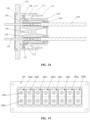
- the socket 100 is configured to be connected to eight plugs 200 by insertion, namely a plug A 200a, a plug B 200b, a plug C 200c, a plug D 200d, a plug E 200e, a plug F 200f, a plug G 200g, and a plug H 200h. Any two of the eight plugs 200 are the same.
- Each of the eight plugs 200 has two photovoltaic cables 240, which are a positive photovoltaic cable 240a and a negative photovoltaic cable 240b respectively.
- the photovoltaic connector shown in FIG. 19 is mounted to the case 300. It can be known from comparison between FIG. 1 and FIG. 22 that, while having the same photovoltaic cables 240, the photovoltaic connector in FIG. 22 requires a relatively small mounting area, i.e. occupies a relatively small area on the case 300.
- the socket 100 is configured to be connected to fourth plugs 200 by insertion, namely a plug A 200a, a plug B 200b, a plug C 200c, and a plug D 200d. Any two of the four plugs 200 are the same.
- Each of the four plugs 200 has four photovoltaic cables 240, which are two positive photovoltaic cables 240a and two negative photovoltaic cables 240b.
- the socket 100 is configured to be connected to six plugs 200 by insertion, namely a plug A 200a, a plug B 200b, a plug C 200c, a plug D 200d, a plug E 200e, and a plug F 200f.
- the plug A 200a has one positive photovoltaic cable 240a
- the plug B 200b has one negative photovoltaic cable 240b.
- the plug C 200c and the plug D 200d are the same, and each has one positive photovoltaic cable 240a and one negative photovoltaic cable 240b.
- the plug E 200e has six photovoltaic cables 240, which are distributed into three positive photovoltaic cables 240a and three negative photovoltaic cables 240b.
- the plug F 200f has four photovoltaic cables 240, which are distributed into two positive photovoltaic cables 240a and two negative photovoltaic cables 240b.
- the plug 200 may be of other types and distribution, which are not limited to the three embodiments shown in FIG. 19 to FIG. 21 .
- the specific structures of the plug 200 and the socket 100 may be selected according to actual needs.
- the above plug 200 includes a plug housing 210 and a pin 230 arranged in the plug housing 210.
- the plug housing 210 is configured to be inserted into the socket 100.
- One end of the pin 230 is electrically connected to the photovoltaic cable 240 in a fixed manner, and the other end of the pin 230 is configured to be electrically connected to the socket 100.
- the pin 230 and the plug housing 210 are connected in an insulated manner.
- the pin 230 is provided for facilitating the electrical connection between the photovoltaic cable 240 and the socket 100.
- the plug housing 210 is provided for facilitating the insertion between the plug 200 and the socket 100.
- the pin 230 is pressed onto the photovoltaic cable 240. In this way, the fixed connection and the electrical connection are realized at the same time.
- the fixed connection and the electrical connection between the photovoltaic cable 240 and the pin 230 may be realized by other means, which are not limited to the above embodiment.
- the pin 230 is configured to be electrically connected to a conductive member 120 of the socket 100 in a sheathing manner.
- the pin 230 may be configured to sheathe the conductive member 120, or the conductive member 120 may be configured to sheathe the pin 230.
- the pin 230 is configured to cooperate with the conductive member 120 in a sheathing manner to be securely connected.
- the pin 230 may be in transition fit or in interference fit with the conductive member 120, which is not limited in the present embodiment.
- the photovoltaic cable 240 and the plug housing 210 are connected in a sealed manner.
- Methods for the sealed connection may be selected according to actual needs, which is not limited in the present embodiment.
- the pin 230 and the plug housing 210 are connected in an insulated manner.
- the pin 230 and the plug housing 210 may be directly connected in an insulated manner.
- the plug housing 210 may be an insulating member.
- the pin 230 and the plug housing 210 may be indirectly connected in an insulated manner.
- the pin 230 and the plug housing 210 are indirectly connected in an insulated manner through an insulating member.
- the above plug 200 further includes a core 220 for being fixed in the plug housing 210.
- the core 220 is provided with a mounting hole 222.
- the pin 230 is located in the mounting hole 222, and the pin 230 is configured to cooperate with the core 220 in a position-limited manner along an axial direction of the pin 230.
- the core 220 is in connection with the plug housing 210 and the pin 230.
- the core 220 may be an insulating member. In this way, the insulated connection between the pin 230 and the plug housing 210 is realized.
- the pin 230 is entirely located in the mounting hole 222, or the pin 230 extends out of the mounting hole 222, which can be selected according to actual needs.
- the pin 230 is entirely located in the mounting hole 222.
- the conductive member 120 may be configured to insert into the mounting hole 222 and be sheathed in the pin 230.
- the pin 230 is provided with an insertion hole 232, and the conductive member 120 is inserted into the insertion hole 232 of the pin 230.
- one of the pin 230 and the core 220 is provided with a limiting protrusion 223, and the other one of the pin 230 and the core 220 is provided with a limiting groove 231 for cooperating with the limiting protrusion 223.
- the limiting protrusion 223 is provided on the core 220, and the limiting groove 231 is provided on the pin 230.
- the shape, number and size of the limiting protrusion 223 and the limiting groove 231 can be selected according to actual needs.
- the limiting protrusion 223 and the limiting groove 231 are both of an annular shape, and are each arranged along a circumferential direction of the corresponding part where they are located respectively.
- the core 220 and the plug housing 210 are fixedly connected in a detachable manner. Specifically, the core 220 is connected to the plug housing 210 by snap fit. That is, the core 220 and the plug housing 210 are fixedly connected in a detachable manner by snap fit.
- one of the core 220 and the plug housing 210 is provided with a first snap 221, and the other one of the core 220 and the plug housing 210 is provided with a first groove 212 connected to the first snap 221 by snap fit.
- the first snap 221 is provided on the core 220, and the first groove 212 is provided on the plug housing 210.
- the structure, size and number of the first snap 221 and the first groove 212 can be selected according to actual needs.
- two first snaps 221 and two first grooves 212 are provided, and are respectively located at two ends of the corresponding part where they are located respectively.
- the plug 200 includes the plug housing 210, the core 220 and the pin 230, to improve safety, the photovoltaic cable 240 and the plug housing 210 are connected in a sealed manner, and the photovoltaic cable 240 and the core 220 are connected in a sealed manner.
- the plug housing 210 and the core 220 are both connected to the photovoltaic cable 240 in a sealed manner through a cable seal 250.
- the plug housing 210 is provided with a snap hole 213 for being connected to the cable seal 250 by snap fit, and the cable seal 250 is located in the mounting hole 222. It may be appreciated that, the cable seal 250 is located between the plug housing 210 and the core 220.
- one end of the mounting hole 222 close to the snap hole 213 is provided with an expanding hole 2221 for cooperating with the cable seal 250, and the expanding hole 2221 expands from one end of the expanding hole 2221 away from the snap hole 213 to the other end close to the snap hole 213.
- a mounting method for the plug 200 includes the following steps. As shown in FIG. 11 , the cable seal 250 is mounted in the snap hole 213 of the plug housing 210. A cable assembly formed by the photovoltaic cable 240 and the pin 230 passes through the cable seal 250. The limiting groove 231 on the pin 230 is connected to the limiting protrusion 223 on the core 220 by snap fit to achieve position-limit along the axial direction. Under natural conditions, the cable assembly and the core 220 may not loosen and be separated without any external force or tools. As shown in FIG. 12 , the core 220 with the cable assembly is pushed towards a side close to the cable seal 250. That is, the core 220 with the cable assembly is pushed in a direction illustrated by an arrow in FIG. 12 .
- the cable seal 250 may be mounted in the mounting hole 222 of the core 220 first during the mounting process. Specifically, the cable seal 250 is mounted in the expanding hole 2221, as shown in FIG. 13 .
- references may be made to the above descriptions, which are not described in detail herein.
- the plug 200 is configured to be fixedly connected and electrically connected to the socket 100 in a detachable manner.
- the plug housing 210 is configured to be connected to the socket 100 by snap fit. Specifically, one of the socket 100 and the plug housing 210 is provided with a second groove 13, and the other one of the socket 100 and the plug housing 210 is provided with a second snap 211 for cooperating with the second groove 113 by snap fit. To improve appearance and facilitate operation, the second snap 211 is provided on the plug housing 210, and the second groove 113 is provided on the socket 100.
- the structure, size and number of the second snap 211 and the second groove 113 can be selected according to actual needs.
- two second snaps 211 and two second grooves 113 are provided, and are respectively located at two ends of the corresponding part where they are located respectively.
- the photovoltaic cable 240 is configured to be electrically connected to the socket 100 in a detachable manner, such that the plug 200 is configured to be electrically connected to the socket 100 in a detachable manner. If the plug 200 includes a pin 230 and a core 220, then the pin 230 is configured to be electrically connected to the socket 100 in a detachable manner.
- the socket 100 is provided with a slot 111 and a conductive member 120.
- the plug 200 is configured to be inserted into the slot 111, and the photovoltaic cable 240 is configured to be electrically connected to the conductive member 120.
- the plug 200 is configured to be securely connected and electrically connected to the socket 100 in a detachable manner
- the plug 200 is configured to be securely connected to the slot 111 in a detachable manner
- the photovoltaic cable 240 is configured to be electrically connected to the conductive member 120 in a detachable manner.
- the socket 100 is configured to be connected to at least two plugs 200 by insertion, in order to partition different plugs 200, the two or more slots 111 and the two or more plugs 200 are in one-to-one correspondence.
- one of the two or more slots 111 may be provided in correspondence to at least two plugs 200, which is not limited to the above embodiment.
- the slot 111 may also be in one-to-one correspondence to the plug 200. If at least two slots 111 are provided, the at least two slots 111 are distributed along a length direction of the socket 100 one after another. In actual use, the at least two slots 111 may be distributed along a width direction of the socket 100 one after another, which is not limited in the present embodiment.
- the photovoltaic cable 240 and the conductive member 120 are in one-to-one correspondence.
- the conductive member 120 may be in correspondence to at least two photovoltaic cables 240, which is not limited in the present embodiment.
- At least one plug 200 is provided with at least two photovoltaic cables 240, the slot 111 is in one-to-one correspondence to the plug 200, and the photovoltaic cable 240 is in one-to-one correspondence to the conductive member 120, at least two conductive members 120 are provided in at least one slot 111.
- the at least one slot 111 is provided with a partition 130, and the partition 130 partitions two adjacent conductive members 120 in the slot 111.
- the number of the partition 130 can be determined according to the number of the conductive member 120, which is not limited in the present embodiment.
- the conductive member 120 may be entirely located in the slot 111, or may extend out of the slot 111. To facilitate a connection between the socket 100 and devices in the case 300, one end of the conductive member 120 is located in the slot 111, and the other end of the conductive member 120 extends out of the slot 111 from a bottom end of the slot 111.
- the plug 200 is configured to be connected to the socket 100 in a sealed manner.
- the plug 200 is configured to be connected to the socket 100 in a sealed manner through a plug seal 140.
- the plug seal 140 may be arranged on a bottom wall or a side wall of the slot 111. In this case, the plug seal 140 and the plug 100 are joined together. During mounting, the plug seal 140 and the slot 111 are assembled before the plug 200 is mounted. As shown in FIG. 3, FIG. 4 and FIG. 15 , the plug seal 140 is arranged on the bottom wall of the slot 111. In this case, after the plug 200 and the socket 100 are mounted, the plug seal 140 abuts against an end face of the plug 200. As shown in FIG. 18 , the plug seal 140 is arranged on the side wall of the slot 111. In this case, after the plug 200 and the socket 100 are mounted, the plug seal 140 abuts against a side face of the plug 200.
- the plug seal 140 may be arranged on the end face or the side face of the plug 200. In this case, the plug seal 140 and the plug 200 are joined together. During mounting, the plug seal 140 and the plug 200 are assembled before the plug 200 is mounted to the socket 100. Specifically, the plug seal 140 is arranged on the end face of the plug 200. In this case, after the plug 200 and the socket 100 are mounted, the plug seal 140 abuts against the bottom wall of the slot 111. Alternatively, the plug seal 140 is arranged on the side face of the plug 200. In this case, after the plug 200 and the socket 100 are mounted, the plug seal 140 abuts against the side wall of the slot 111.
- the socket 100 is configured to be mounted on the case 300.
- the socket 100 includes a base 110 configured to be fixedly connected to the case 300 in a sealed manner, and the plug 200 is configured to be inserted to the base 110.
- the slot 111 and the fixation hole 112 are both provided on the base 110. If the conductive member 120 passes through the slot 111, the conductive member 120 passes through the base 110, as shown in FIG. 5 , and FIG. 16 to FIG. 18 .
- the base 110 is provided with a socket seal 150 configured to be connected to the case 300 in a sealed manner.
- the socket seal 150 is arranged on a bottom face of the base 110.
- the base 110 may be connected to the case 300 in a sealed manner by other means, which is not limited in the present embodiment.
Landscapes
- Connector Housings Or Holding Contact Members (AREA)
- Photovoltaic Devices (AREA)
Abstract
Disclosed in the present invention is a photovoltaic connector, comprising a socket, and plugs configured to be inserted into the socket, wherein each plug is provided with at least one photovoltaic cable configured to be electrically connected to the socket; the socket is configured to be connected to at least two plugs in an inserted manner; and/or, the number of the photovoltaic cables of at least one plug is at least two. In the photovoltaic connector, if the socket is configured to be connected to at least two plugs in an inserted manner, in comparison with the prior art in which sockets correspond to plugs on a one-to-one basis, the number of the sockets is reduced, and the area on the box that is occupied by the socket is reduced, thereby reducing the overall size of the box. If the number of the photovoltaic cables of at least one plug is at least two, in comparison with the prior art in which each plug is provided with one photovoltaic cable, the number of the plugs and an operation space to be reserved for plugging and unplugging the plug are reduced, and the area on the box that is occupied by the photovoltaic connector is reduced, thereby reducing the overall size of the box.
Description
- The present application claims the priority to
Chinese Patent Application No. 202221074330.1, titled "PHOTOVOLTAIC CONNECTOR", filed with the China National Intellectual Property Administration on May 06, 2022 - The present application relates to the technical field of photovoltaic power generation, and in particular to a photovoltaic connector.
- In a photovoltaic system, photovoltaic cables are generally connected by a photovoltaic connector. For example, an inverter, a junction box and the like may be provided with the photovoltaic connector to connect to the photovoltaic cables.
- As shown in
FIG. 1 , the photovoltaic connector mainly includes sockets 01 andplugs 02 in one-to-one correspondence. Specifically, the sockets 01 are mounted to acase 03, and eachplug 02 is configured to be in cooperation with the corresponding socket 01 by insertion. - In the above structure, each socket 01 has to be independently mounted to the
case 03. Thus, a mounting space needs to be reserved between each two adjacent sockets 01. As a result, the photovoltaic connector may occupy a large area on thecase 03, making theentire case 03 relatively large. - Moreover, each
plug 02 is provided with a photovoltaic cable, and eachplug 02 has to be plugged and unplugged separately. Therefore, an operation space for plugging and unplugging theplug 02 may also be reserved between each two adjacent sockets 01. As the operation space for plugging and unplugging theplug 02 is relatively large, the area occupied by the photovoltaic connector may be further enlarged, and the size ofcase 03 may be further increased. - In summary, a problem to be solved by those skilled in the art is how to design the photovoltaic connector to reduce the area on the case occupied by the photovoltaic connector and further reduce the size of the case.
- In view of this, an object of the present application is to provide a photovoltaic connector, which reduces an area on a case occupied by the photovoltaic connector and further reduces the size of the case.
- To achieve the above object, the following technical solutions are provided according to the present application.
- A photovoltaic connector includes a socket and a plug that is configured to be connected to the socket by insertion,
- the plug is provided with at least one photovoltaic cable, and the at least one photovoltaic cable is configured to be electrically connected to the socket; and
- the socket is configured to be connected to at least two plugs by insertion; and/or at least one plug is provided with at least two photovoltaic cables.
- Optionally, in a case that at least one plug is provided with at least two photovoltaic cables, the at least two photovoltaic cables of at least one plug are both positive photovoltaic cables, and/or the at least two photovoltaic cables are both negative photovoltaic cables, and/or, at least one of the at least two photovoltaic cables is a positive photovoltaic cable and at least another one of the at least two photovoltaic cables is a negative photovoltaic cable.
- Optionally, the at least one plug includes a plug housing and a pin provided in the plug housing and the plug housing is configured to be inserted into the socket, one end of the pin is electrically connected to the photovoltaic cable in a fixed manner, and the other end of the pin is configured to be electrically connected to the socket, and the pin and the plug housing are connected in an insulated manner.
- Optionally, the pin is configured to be electrically connected to a conductive member of the socket in a sheathing manner, and/or the photovoltaic cable is connected to the plug housing in a sealed manner.
- Optionally, the plug includes a core fixed in the plug housing, the core is provided with a mounting hole, the pin is located in the mounting hole, and the pin is configured to cooperate with the core in a position-limited manner along an axial direction of the pin.
- Optionally, the core is connected to the plug housing by snap fit.
- Optionally, the plug housing and the core are both connected to the photovoltaic cable in a sealed manner through a cable seal, and the plug housing is provided with a snap hole for being connected to the cable seal by snap fit, and the cable seal is located in the mounting hole.
- Optionally, one end of the mounting hole close to the snap hole is provided with an expanding hole for cooperating with the cable seal, and the expanding hole expands from one end of the expanding hole away from the snap hole to the other end of the expanding hole close to the snap hole.
- Optionally, the plug housing is configured to be connected to the socket by snap fit.
- Optionally, the socket is provided with a slot and a conductive member, and the plug is configured to be inserted into the slot, and the photovoltaic cable is configured to be electrically connected to the conductive member.
- Optionally, the slot is in one-to-one correspondence to the plug, and/or the photovoltaic cable is in one-to-one correspondence to the conductive member.
- Optionally, one end of the conductive member is located in the slot, and the other end of the conductive member extends out of the slot from a bottom end of the slot.
- Optionally, the plug is configured to be connected to the socket in a sealed manner through a plug seal, and the plug seal is provided on a bottom wall or a side wall of the slot, or the plug seal is provided on an end face or a side face of the plug.
- Optionally, the socket includes a base that is configured to be fixedly connected to a case in a sealed manner, and the plug is configured to be inserted into the base.
- Optionally, the base is provided with a socket seal that is configured to be connected to the case in a sealed manner.
- According to the photovoltaic connector provided in the present application, if the socket is configured to be connected to at least two plugs by insertion, i.e. the socket is in correspondence to at least two plugs, compared with a solution in the prior art that sockets and plugs are in one-to-one correspondence, the number of the socket is effectively decreased, thereby reducing the required mounting area for the socket, i.e. reducing the area on the case occupied by the socket, and further reducing the size of the entire case. If at least one plug is provided with at least two photovoltaic cables, compared with a solution in the prior art that each plug is provided with one photovoltaic cable, the number of the plug is effectively decreased, and the operation space reserved for plugging and unplugging the plug is effectively reduced, thereby reducing the required mounting area for the photovoltaic connector, i.e. reducing the area on the case occupied by the photovoltaic connector, and further reducing the size of the entire case.
- Moreover, according to the photovoltaic connector provided in the present application, if the socket is connected to at least two plugs, the number of the socket is decreased, thereby simplifying mounting of the photovoltaic connector and improving mounting efficiency. If at least one plug is provided with at least two photovoltaic cables, the number of the plug is decreased, thereby simplifying mounting of the photovoltaic connector and improving mounting efficiency.
- For more clearly illustrating embodiments of the present application or the technical solutions in the prior art, drawings referred to describe the embodiments or the prior art will be briefly described hereinafter. Apparently, the drawings in the following description are only some examples of the present application, and for those skilled in the art, other drawings may be obtained based on these drawings without any creative efforts.
-
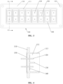
FIG. 1 is a view showing the distribution of photovoltaic connectors on an case according to the prior art; -
FIG. 2 is an exploded view of a photovoltaic connector according to an embodiment of the present application; -
FIG. 3 is a front view of a socket of the photovoltaic connector according to the embodiment of the present application; -
FIG. 4 is a sectional view taken along a line A-A inFIG. 3 ; -
FIG. 5 is a bottom view of the socket of the photovoltaic connector according to the embodiment of the present application; -
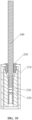
FIG. 6 is an exploded view of a plug of the photovoltaic connector according to the embodiment of the present application; -
FIG. 7 is a front view of the plug of the photovoltaic connector according to the embodiment of the present application; -
FIG. 8 is a sectional view taken along a line B-B inFIG. 7 ; -
FIG. 9 is a top view of the plug of the photovoltaic connector according to the embodiment of the present application; -
FIG. 10 is a sectional view taken along a line C-C inFIG. 9 ; -
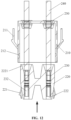
FIG. 11 is a schematic view showing mounting of the plug of the photovoltaic connector according to the embodiment of the present application; -
FIG. 12 is a schematic view showing mounting of a plug housing and a core of the photovoltaic connector according to the embodiment of the present application; -
FIG. 13 is another schematic view showing mounting of the plug of the photovoltaic connector according to the embodiment of the present application; -
FIG. 14 is a front view of a photovoltaic connector according to an embodiment of the present application; -
FIG. 15 is a sectional view taken along a line D-D inFIG. 14 ; -
FIG. 16 is a sectional view taken along a line E-E inFIG. 14 ; -
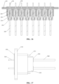
FIG. 17 is a side view of the photovoltaic connector according to the embodiment of the present application; -
FIG. 18 is another sectional view of a photovoltaic connector according to an embodiment of the present application; -
FIG. 19 is a schematic structural view of a photovoltaic connector according to an embodiment of the present application; -
FIG. 20 is a schematic structural view of another photovoltaic connector according to an embodiment of the present application; -
FIG. 21 is a schematic structural view of yet another photovoltaic connector according to an embodiment of the present application; and -
FIG. 22 is a view showing the distribution of the photovoltaic connector on an case according to an embodiment of the present application. - Technical solutions according to the embodiments of the present application will be described clearly and completely as follows in conjunction with the accompany drawings in the embodiments of the present application. It is obvious that the described embodiments are only a part of the embodiments according to the present application, rather than all of the embodiments. All the other embodiments obtained by those skilled in the art based on the embodiments in the present application without any creative work belong to the scope of protection of the present application.
- As shown in
FIG. 2 , a photovoltaic connector according to an embodiment of the present application includes asocket 100 and aplug 200 that is configured to be connected to thesocket 100 by insertion. It may be appreciated that, theplug 200 and thesocket 100 are connected by insertion to achieve an electrical connection between theplug 200 and thesocket 100. - As shown in
FIG. 22 , thesocket 100 is configured to be arranged on acase 300 of electrical equipment. To facilitate maintenance, thesocket 100 is configured to be arranged on thecase 300 in a detachable manner. Specifically, thesocket 100 is configured to be arranged on thecase 300 in a detachable manner through a fastener, and thesocket 100 is provided with afixation hole 112 for the fastener to pass through. - The
plug 200 is provided with at least onephotovoltaic cable 240, and thephotovoltaic cable 240 is configured to be electrically connected to thesocket 100. - In the above photovoltaic connector, the
socket 100 is configured to be connected to at least twoplugs 200 by insertion, and/or at least oneplug 200 is provided with at least two photovoltaic cables 20. - If the
socket 100 is configured to be connected to at least twoplugs 200 by insertion, i.e. thesocket 100 is in correspondence to at least twoplugs 200, compared with a solution in the prior art that sockets and plugs are in one-to-one correspondence, the number of thesocket 100 is effectively decreased, thereby reducing the required mounting area for thesocket 100, i.e. reducing the area on thecase 300 occupied by thesocket 100, and further reducing the size of theentire case 300. Moreover, the number of thesocket 100 is decreased, thereby simplifying mounting of the photovoltaic connector and improving mounting efficiency. Since the number of thesocket 100 is decreased, the cost of thesocket 100 is reduced, thereby reducing the cost of the entire photovoltaic connector. - If at least one
plug 200 is provided with at least twophotovoltaic cables 240, compared with a solution in the prior art that each plug is provided with one photovoltaic cable, the number of theplug 200 is effectively decreased, and the operation space reserved for plugging and unplugging theplug 200 is effectively reduced, thereby reducing the required mounting area for the photovoltaic connector, i.e. reducing the area on thecase 300 occupied by the photovoltaic connector, and further reducing the size of theentire case 300. Moreover, the number of theplug 200 is decreased, thereby simplifying mounting of the photovoltaic connector and improving mounting efficiency. Since the number of theplug 200 is decreased, the cost of theplug 200 is reduced, thereby reducing the cost of the entire photovoltaic connector. - Therefore, with the photovoltaic connector according to the above embodiment, the occupied area on the
case 300 is reduced, thereby reducing the size of theentire case 300. Furthermore, the mounting of the photovoltaic connector is simplified, which increases the mounting efficiency. Moreover, the cost of the entire photovoltaic connector is reduced. - In the above photovoltaic connector, if the
socket 100 is configured to be connected to at least twoplugs 200 by insertion, at least two of theplugs 200 may be the same, and/or at least two of theplugs 200 may be different. - It should be noted that, the expression that two
plugs 200 may be the same refers to that they have the same structure and the same size. The expression that twoplugs 200 may be different refers to that they may have different structures and/or different sizes. Specifically, if the twoplugs 200 have different structures, they may have differentphotovoltaic cables 240. - It may be appreciated that, the expression that the two
plugs 200 may have differentphotovoltaic cables 240 refers to that they may have different number ofphotovoltaic cables 240 or havephotovoltaic cables 240 with different polarities. - To facilitate manufacturing and mounting, if the
socket 100 is configured to be connected to at least twoplugs 200 by insertion, at least two of theplugs 200 may have samephotovoltaic cables 240 or have differentphotovoltaic cables 240. - In the above photovoltaic connector, for the
plug 200 that has at least twophotovoltaic cables 240, at least two of thephotovoltaic cables 240 may have same polarities, and/or have different polarities, which may be selected according to actual needs. - Specifically, if at least one
plug 200 is provided with at least twophotovoltaic cables 240, the at least twophotovoltaic cables 240 of at least oneplug 200 may be both positivephotovoltaic cables 240a, and/or the at least twophotovoltaic cables 240 may be both negativephotovoltaic cables 240b, and/or at least one of thephotovoltaic cables 240 may be the positivephotovoltaic cable 240a and at least another one of thephotovoltaic cables 240 may be the negativephotovoltaic cable 240b. - As shown in
FIG. 19 , thesocket 100 is configured to be connected to eightplugs 200 by insertion, namely aplug A 200a, aplug B 200b, aplug C 200c, aplug D 200d, aplug E 200e, aplug F 200f, aplug G 200g, and aplug H 200h. Any two of the eightplugs 200 are the same. Each of the eightplugs 200 has twophotovoltaic cables 240, which are a positivephotovoltaic cable 240a and a negativephotovoltaic cable 240b respectively. As shown inFIG. 22 , the photovoltaic connector shown inFIG. 19 is mounted to thecase 300. It can be known from comparison betweenFIG. 1 andFIG. 22 that, while having the samephotovoltaic cables 240, the photovoltaic connector inFIG. 22 requires a relatively small mounting area, i.e. occupies a relatively small area on thecase 300. - As shown in
FIG. 20 , thesocket 100 is configured to be connected tofourth plugs 200 by insertion, namely aplug A 200a, aplug B 200b, aplug C 200c, and aplug D 200d. Any two of the fourplugs 200 are the same. Each of the fourplugs 200 has fourphotovoltaic cables 240, which are two positivephotovoltaic cables 240a and two negativephotovoltaic cables 240b. - As shown in
FIG. 21 , thesocket 100 is configured to be connected to sixplugs 200 by insertion, namely aplug A 200a, aplug B 200b, aplug C 200c, aplug D 200d, aplug E 200e, and aplug F 200f. Theplug A 200a has one positivephotovoltaic cable 240a, and theplug B 200b has one negativephotovoltaic cable 240b. Theplug C 200c and theplug D 200d are the same, and each has one positivephotovoltaic cable 240a and one negativephotovoltaic cable 240b. Theplug E 200e has sixphotovoltaic cables 240, which are distributed into three positivephotovoltaic cables 240a and three negativephotovoltaic cables 240b. Theplug F 200f has fourphotovoltaic cables 240, which are distributed into two positivephotovoltaic cables 240a and two negativephotovoltaic cables 240b. - In actual use, the
plug 200 may be of other types and distribution, which are not limited to the three embodiments shown inFIG. 19 to FIG. 21 . - In the above photovoltaic connector, the specific structures of the
plug 200 and thesocket 100 may be selected according to actual needs. - In an embodiment, as shown in
FIG. 6 to FIG. 10 , theabove plug 200 includes aplug housing 210 and apin 230 arranged in theplug housing 210. Theplug housing 210 is configured to be inserted into thesocket 100. One end of thepin 230 is electrically connected to thephotovoltaic cable 240 in a fixed manner, and the other end of thepin 230 is configured to be electrically connected to thesocket 100. Thepin 230 and theplug housing 210 are connected in an insulated manner. - In the above structure, the
pin 230 is provided for facilitating the electrical connection between thephotovoltaic cable 240 and thesocket 100. Theplug housing 210 is provided for facilitating the insertion between theplug 200 and thesocket 100. - To facilitate the connection between the
photovoltaic cable 240 and thepin 230, thepin 230 is pressed onto thephotovoltaic cable 240. In this way, the fixed connection and the electrical connection are realized at the same time. - In actual use, the fixed connection and the electrical connection between the
photovoltaic cable 240 and thepin 230 may be realized by other means, which are not limited to the above embodiment. - In the above photovoltaic connector, to facilitate the electrical connection between the
pin 230 and thesocket 100, thepin 230 is configured to be electrically connected to aconductive member 120 of thesocket 100 in a sheathing manner. - Specifically, the
pin 230 may be configured to sheathe theconductive member 120, or theconductive member 120 may be configured to sheathe thepin 230. To increase stability, thepin 230 is configured to cooperate with theconductive member 120 in a sheathing manner to be securely connected. For example, thepin 230 may be in transition fit or in interference fit with theconductive member 120, which is not limited in the present embodiment. - To increase reliability, the
photovoltaic cable 240 and theplug housing 210 are connected in a sealed manner. Methods for the sealed connection may be selected according to actual needs, which is not limited in the present embodiment. - In the above photovoltaic connector, the
pin 230 and theplug housing 210 are connected in an insulated manner. Thepin 230 and theplug housing 210 may be directly connected in an insulated manner. Specifically, theplug housing 210 may be an insulating member. Certainly, thepin 230 and theplug housing 210 may be indirectly connected in an insulated manner. Specifically, thepin 230 and theplug housing 210 are indirectly connected in an insulated manner through an insulating member. - To facilitate mounting of the
pin 230, theabove plug 200 further includes acore 220 for being fixed in theplug housing 210. Thecore 220 is provided with a mountinghole 222. Thepin 230 is located in the mountinghole 222, and thepin 230 is configured to cooperate with the core 220 in a position-limited manner along an axial direction of thepin 230. - In the above structure, the
core 220 is in connection with theplug housing 210 and thepin 230. In this structure, thecore 220 may be an insulating member. In this way, the insulated connection between thepin 230 and theplug housing 210 is realized. - In the
above plug 200, thepin 230 is entirely located in the mountinghole 222, or thepin 230 extends out of the mountinghole 222, which can be selected according to actual needs. To facilitate mounting, thepin 230 is entirely located in the mountinghole 222. In this case, if thepin 230 is configured to be electrically connected to theconductive member 120 in a sheathing manner, theconductive member 120 may be configured to insert into the mountinghole 222 and be sheathed in thepin 230. Specifically, thepin 230 is provided with aninsertion hole 232, and theconductive member 120 is inserted into theinsertion hole 232 of thepin 230. - To facilitate the position limit along the axial direction, as shown in
FIG. 11 andFIG. 13 , one of thepin 230 and thecore 220 is provided with a limitingprotrusion 223, and the other one of thepin 230 and thecore 220 is provided with a limitinggroove 231 for cooperating with the limitingprotrusion 223. To facilitate mounting and increasing stability, the limitingprotrusion 223 is provided on thecore 220, and the limitinggroove 231 is provided on thepin 230. - The shape, number and size of the limiting
protrusion 223 and the limitinggroove 231 can be selected according to actual needs. To simplify the structure, the limitingprotrusion 223 and the limitinggroove 231 are both of an annular shape, and are each arranged along a circumferential direction of the corresponding part where they are located respectively. - To mount and dismount, the
core 220 and theplug housing 210 are fixedly connected in a detachable manner. Specifically, thecore 220 is connected to theplug housing 210 by snap fit. That is, thecore 220 and theplug housing 210 are fixedly connected in a detachable manner by snap fit. - As shown in
FIG. 8 , andFIG. 11 toFIG. 13 , one of thecore 220 and theplug housing 210 is provided with afirst snap 221, and the other one of thecore 220 and theplug housing 210 is provided with afirst groove 212 connected to thefirst snap 221 by snap fit. To facilitate mounting, thefirst snap 221 is provided on thecore 220, and thefirst groove 212 is provided on theplug housing 210. - The structure, size and number of the
first snap 221 and thefirst groove 212 can be selected according to actual needs. To simplify the structure and ensure the stability, twofirst snaps 221 and twofirst grooves 212 are provided, and are respectively located at two ends of the corresponding part where they are located respectively. - If the
plug 200 includes theplug housing 210, thecore 220 and thepin 230, to improve safety, thephotovoltaic cable 240 and theplug housing 210 are connected in a sealed manner, and thephotovoltaic cable 240 and thecore 220 are connected in a sealed manner. In an embodiment, theplug housing 210 and thecore 220 are both connected to thephotovoltaic cable 240 in a sealed manner through acable seal 250. Theplug housing 210 is provided with asnap hole 213 for being connected to thecable seal 250 by snap fit, and thecable seal 250 is located in the mountinghole 222. It may be appreciated that, thecable seal 250 is located between theplug housing 210 and thecore 220. - To facilitate mounting, one end of the mounting
hole 222 close to thesnap hole 213 is provided with an expandinghole 2221 for cooperating with thecable seal 250, and the expandinghole 2221 expands from one end of the expandinghole 2221 away from thesnap hole 213 to the other end close to thesnap hole 213. - A mounting method for the
plug 200 includes the following steps. As shown inFIG. 11 , thecable seal 250 is mounted in thesnap hole 213 of theplug housing 210. A cable assembly formed by thephotovoltaic cable 240 and thepin 230 passes through thecable seal 250. The limitinggroove 231 on thepin 230 is connected to the limitingprotrusion 223 on thecore 220 by snap fit to achieve position-limit along the axial direction. Under natural conditions, the cable assembly and thecore 220 may not loosen and be separated without any external force or tools. As shown inFIG. 12 , thecore 220 with the cable assembly is pushed towards a side close to thecable seal 250. That is, thecore 220 with the cable assembly is pushed in a direction illustrated by an arrow inFIG. 12 . With a click, thefirst snap 221 of thecore 220 is popped into thefirst groove 212 of theplug housing 210, and thecable seal 250 is tightly pressed, as shown inFIG. 8 . In this way, a sealing between thephotovoltaic cable 240 and theplug housing 210 is realized, and the pulling strength of thephotovoltaic cable 240 is improved. - In actual use, the
cable seal 250 may be mounted in the mountinghole 222 of the core 220 first during the mounting process. Specifically, thecable seal 250 is mounted in the expandinghole 2221, as shown inFIG. 13 . For other steps, references may be made to the above descriptions, which are not described in detail herein. - In the above photovoltaic connector, to facilitate mounting and dismounting of the
plug 200, theplug 200 is configured to be fixedly connected and electrically connected to thesocket 100 in a detachable manner. - To facilitate the fixed connection in the detachable manner, the
plug housing 210 is configured to be connected to thesocket 100 by snap fit. Specifically, one of thesocket 100 and theplug housing 210 is provided with a second groove 13, and the other one of thesocket 100 and theplug housing 210 is provided with asecond snap 211 for cooperating with thesecond groove 113 by snap fit. To improve appearance and facilitate operation, thesecond snap 211 is provided on theplug housing 210, and thesecond groove 113 is provided on thesocket 100. - The structure, size and number of the
second snap 211 and thesecond groove 113 can be selected according to actual needs. To simplify the structure and ensure the stability, twosecond snaps 211 and twosecond grooves 113 are provided, and are respectively located at two ends of the corresponding part where they are located respectively. - In the above photovoltaic connector, the
photovoltaic cable 240 is configured to be electrically connected to thesocket 100 in a detachable manner, such that theplug 200 is configured to be electrically connected to thesocket 100 in a detachable manner. If theplug 200 includes apin 230 and acore 220, then thepin 230 is configured to be electrically connected to thesocket 100 in a detachable manner. - As shown in
FIG. 3 and FIG. 4 , thesocket 100 is provided with aslot 111 and aconductive member 120. As shown inFIG. 14 and FIG. 15 , theplug 200 is configured to be inserted into theslot 111, and thephotovoltaic cable 240 is configured to be electrically connected to theconductive member 120. - If the
plug 200 is configured to be securely connected and electrically connected to thesocket 100 in a detachable manner, theplug 200 is configured to be securely connected to theslot 111 in a detachable manner, and thephotovoltaic cable 240 is configured to be electrically connected to theconductive member 120 in a detachable manner. - If two or
more slots 111 and two ormore plugs 200 are provided and thesocket 100 is configured to be connected to at least twoplugs 200 by insertion, in order to partitiondifferent plugs 200, the two ormore slots 111 and the two ormore plugs 200 are in one-to-one correspondence. Certainly, one of the two ormore slots 111 may be provided in correspondence to at least twoplugs 200, which is not limited to the above embodiment. - It may be appreciated that, if the
socket 100 is configured to be connected to oneplug 200 by insertion, theslot 111 may also be in one-to-one correspondence to theplug 200. If at least twoslots 111 are provided, the at least twoslots 111 are distributed along a length direction of thesocket 100 one after another. In actual use, the at least twoslots 111 may be distributed along a width direction of thesocket 100 one after another, which is not limited in the present embodiment. - To improve the adaptability of the
socket 100 to theplug 200, thephotovoltaic cable 240 and theconductive member 120 are in one-to-one correspondence. Certainly, theconductive member 120 may be in correspondence to at least twophotovoltaic cables 240, which is not limited in the present embodiment. - If at least one
plug 200 is provided with at least twophotovoltaic cables 240, theslot 111 is in one-to-one correspondence to theplug 200, and thephotovoltaic cable 240 is in one-to-one correspondence to theconductive member 120, at least twoconductive members 120 are provided in at least oneslot 111. To partition theconductive members 120 in theslot 111, the at least oneslot 111 is provided with apartition 130, and thepartition 130 partitions two adjacentconductive members 120 in theslot 111. - The number of the
partition 130 can be determined according to the number of theconductive member 120, which is not limited in the present embodiment. - In the
socket 100, theconductive member 120 may be entirely located in theslot 111, or may extend out of theslot 111. To facilitate a connection between thesocket 100 and devices in thecase 300, one end of theconductive member 120 is located in theslot 111, and the other end of theconductive member 120 extends out of theslot 111 from a bottom end of theslot 111. - To increase safety and reliability, the
plug 200 is configured to be connected to thesocket 100 in a sealed manner. Optionally, theplug 200 is configured to be connected to thesocket 100 in a sealed manner through aplug seal 140. - In one aspect, the
plug seal 140 may be arranged on a bottom wall or a side wall of theslot 111. In this case, theplug seal 140 and theplug 100 are joined together. During mounting, theplug seal 140 and theslot 111 are assembled before theplug 200 is mounted. As shown inFIG. 3, FIG. 4 andFIG. 15 , theplug seal 140 is arranged on the bottom wall of theslot 111. In this case, after theplug 200 and thesocket 100 are mounted, theplug seal 140 abuts against an end face of theplug 200. As shown inFIG. 18 , theplug seal 140 is arranged on the side wall of theslot 111. In this case, after theplug 200 and thesocket 100 are mounted, theplug seal 140 abuts against a side face of theplug 200. - In the other aspect, the
plug seal 140 may be arranged on the end face or the side face of theplug 200. In this case, theplug seal 140 and theplug 200 are joined together. During mounting, theplug seal 140 and theplug 200 are assembled before theplug 200 is mounted to thesocket 100. Specifically, theplug seal 140 is arranged on the end face of theplug 200. In this case, after theplug 200 and thesocket 100 are mounted, theplug seal 140 abuts against the bottom wall of theslot 111. Alternatively, theplug seal 140 is arranged on the side face of theplug 200. In this case, after theplug 200 and thesocket 100 are mounted, theplug seal 140 abuts against the side wall of theslot 111. - In the above photovoltaic connector, the
socket 100 is configured to be mounted on thecase 300. To increases safety and reliability, thesocket 100 includes a base 110 configured to be fixedly connected to thecase 300 in a sealed manner, and theplug 200 is configured to be inserted to thebase 110. It may be appreciated that, theslot 111 and thefixation hole 112 are both provided on thebase 110. If theconductive member 120 passes through theslot 111, theconductive member 120 passes through thebase 110, as shown inFIG. 5 , andFIG. 16 toFIG. 18 . - Specifically, as shown in
FIG. 4 ,FIG. 5 , andFIG. 15 toFIG. 18 , thebase 110 is provided with asocket seal 150 configured to be connected to thecase 300 in a sealed manner. To facilitate sealing, thesocket seal 150 is arranged on a bottom face of thebase 110. - In actual use, the
base 110 may be connected to thecase 300 in a sealed manner by other means, which is not limited in the present embodiment. - Based on the above description of the disclosed embodiments, those skilled in the art are capable of carrying out or using the present application. It is obvious for those skilled in the art to make many modifications to these embodiments. The general principle defined herein may be applied to other embodiments without departing from the spirit or scope of the present application. Therefore, the present application is not limited to the embodiments illustrated herein, but should be defined by the broadest scope consistent with the principle and novel features disclosed herein.
Claims (15)
- A photovoltaic connector, comprising a socket and at least one plug that is configured to be connected to the socket by insertion, whereinthe plug is provided with at least one photovoltaic cable, and the at least one photovoltaic cable is configured to be electrically connected to the socket; andthe socket is configured to be connected to at least two plugs by insertion, and/or the at least one plug is provided with at least two photovoltaic cables.
- The photovoltaic connector according to claim 1, wherein in a case that the at least one plug is provided with at least two photovoltaic cables, the at least two photovoltaic cables of at least one plug are both positive photovoltaic cables, and/or the at least two photovoltaic cables are both negative photovoltaic cables, and/or at least one of the at least two photovoltaic cables is a positive photovoltaic cable and at least another one of the at least two photovoltaic cables is a negative photovoltaic cable.
- The photovoltaic connector according to claim 1, whereinthe plug comprises a plug housing and a pin provided in the plug housing, and the plug housing is configured to be inserted into the socket;one end of the pin is electrically connected to the photovoltaic cable in a fixed manner, the other end of the pin is configured to be electrically connected to the socket; andthe pin and the plug housing are connected in an insulated manner.
- The photovoltaic connector according to claim 3, wherein the pin is configured to be electrically connected to a conductive member of the socket in a sheathing manner, and/or the photovoltaic cable is connected to the plug housing in a sealed manner.
- The photovoltaic connector according to claim 3, wherein the plug comprises a core fixed in the plug housing, the core is provided with a mounting hole, the pin is located in the mounting hole, and the pin is configured to cooperate with the core in a position-limited manner along an axial direction of the pin.
- The photovoltaic connector according to claim 5, wherein the core is connected to the plug housing by snap fit.
- The photovoltaic connector according to claim 5, wherein the plug housing and the core are both connected to the photovoltaic cable in a sealed manner through a cable seal, the plug housing is provided with a snap hole for being connected to the cable seal by snap fit, and the cable seal is located in the mounting hole.
- The photovoltaic connector according to claim 7, wherein one end of the mounting hole close to the snap hole is provided with an expanding hole cooperating with the cable seal, and the expanding hole expands from one end of the expanding hole away from the snap hole to the other end of the expanding hole close to the snap hole.
- The photovoltaic connector according to claim 3, wherein the plug housing is configured to be connected to the socket by snap fit.
- The photovoltaic connector according to claim 1, wherein the socket is provided with a slot and a conductive member, the plug is configured to be inserted into the slot, and the photovoltaic cable is configured to be electrically connected to the conductive member.
- The photovoltaic connector according to claim 10, wherein the slot is in one-to-one correspondence to the plug and/or the photovoltaic cable is in one-to-one correspondence to the conductive member.
- The photovoltaic connector according to claim 10, wherein one end of the conductive member is located in the slot, and the other end of the conductive member extends out of the slot from a bottom end of the slot.
- The photovoltaic connector according to claim 10, wherein the plug is configured to be connected to the socket in a sealed manner through a plug seal, the plug seal is provided on a bottom wall or a side wall of the slot, or the plug seal is provided on an end face or a side face of the plug.
- The photovoltaic connector according to any one of claims 1 to 13, wherein the socket comprises a base that is configured to be fixedly connected to a case in a sealed manner, and the plug is configured to be inserted into the base.
- The photovoltaic connector according to claim 14, wherein the base is provided with a socket seal that is configured to be connected to the case in a sealed manner.
Applications Claiming Priority (2)
| Application Number | Priority Date | Filing Date | Title |
|---|---|---|---|
| CN202221074330.1U CN217427153U (en) | 2022-05-06 | 2022-05-06 | Photovoltaic connector |
| PCT/CN2022/142189 WO2023213090A1 (en) | 2022-05-06 | 2022-12-27 | Photovoltaic connector |
Publications (1)
| Publication Number | Publication Date |
|---|---|
| EP4521562A1 true EP4521562A1 (en) | 2025-03-12 |
Family
ID=83184734
Family Applications (1)
| Application Number | Title | Priority Date | Filing Date |
|---|---|---|---|
| EP22940784.6A Pending EP4521562A1 (en) | 2022-05-06 | 2022-12-27 | Photovoltaic connector |
Country Status (7)
| Country | Link |
|---|---|
| US (1) | US20250149818A1 (en) |
| EP (1) | EP4521562A1 (en) |
| JP (1) | JP2025502374A (en) |
| KR (1) | KR20240124341A (en) |
| CN (1) | CN217427153U (en) |
| AU (1) | AU2022456807A1 (en) |
| WO (1) | WO2023213090A1 (en) |
Families Citing this family (2)
| Publication number | Priority date | Publication date | Assignee | Title |
|---|---|---|---|---|
| CN217427153U (en) * | 2022-05-06 | 2022-09-13 | 阳光电源股份有限公司 | Photovoltaic connector |
| CN220474938U (en) * | 2023-03-31 | 2024-02-09 | 阳光电源股份有限公司 | Connector components and connection structures |
Family Cites Families (11)
| Publication number | Priority date | Publication date | Assignee | Title |
|---|---|---|---|---|
| JPH0438474Y2 (en) * | 1986-04-30 | 1992-09-09 | ||
| JP3503738B2 (en) * | 1998-11-04 | 2004-03-08 | 住友電装株式会社 | Split connector |
| JP3647674B2 (en) * | 1999-06-15 | 2005-05-18 | 矢崎総業株式会社 | Waterproof connector and method for assembling the waterproof connector |
| JP2003151677A (en) * | 2001-11-16 | 2003-05-23 | Yazaki Corp | Joint connector fitting method and fitting structure |
| JP2007265673A (en) * | 2006-03-27 | 2007-10-11 | Jtekt Corp | connector |
| JP2010250989A (en) * | 2009-04-13 | 2010-11-04 | Smk Corp | Waterproof connector and solar power generator |
| DE102013110545A1 (en) * | 2013-09-24 | 2015-03-26 | Phoenix Contact Gmbh & Co. Kg | Device for the sealing passage of lines through a separating element |
| US20180316201A1 (en) * | 2017-01-25 | 2018-11-01 | Halo International SEZC Ltd. | Portable power strip |
| JP7265426B2 (en) * | 2019-06-19 | 2023-04-26 | 日本航空電子工業株式会社 | Collective waterproof receptacle connector |
| CN217427153U (en) * | 2022-05-06 | 2022-09-13 | 阳光电源股份有限公司 | Photovoltaic connector |
| CN217607125U (en) * | 2022-06-21 | 2022-10-18 | 宁波高松新能源科技有限公司 | Connector socket, connector plug and connector |
-
2022
- 2022-05-06 CN CN202221074330.1U patent/CN217427153U/en active Active
- 2022-12-27 KR KR1020247023411A patent/KR20240124341A/en active Pending
- 2022-12-27 JP JP2024542339A patent/JP2025502374A/en active Pending
- 2022-12-27 US US18/832,888 patent/US20250149818A1/en active Pending
- 2022-12-27 WO PCT/CN2022/142189 patent/WO2023213090A1/en not_active Ceased
- 2022-12-27 AU AU2022456807A patent/AU2022456807A1/en not_active Abandoned
- 2022-12-27 EP EP22940784.6A patent/EP4521562A1/en active Pending
Also Published As
| Publication number | Publication date |
|---|---|
| KR20240124341A (en) | 2024-08-16 |
| WO2023213090A1 (en) | 2023-11-09 |
| US20250149818A1 (en) | 2025-05-08 |
| JP2025502374A (en) | 2025-01-24 |
| AU2022456807A1 (en) | 2024-08-01 |
| CN217427153U (en) | 2022-09-13 |
Similar Documents
| Publication | Publication Date | Title |
|---|---|---|
| US20250149818A1 (en) | Photovoltaic connector | |
| CN113314904A (en) | Gap fit type plugging device with operating mechanism | |
| US12368253B2 (en) | Compact cable connector and connector assembly with stability | |
| WO2023150948A1 (en) | Single pair ethernet connection system | |
| EP0335721A2 (en) | Waterproof electric connector | |
| CN213636436U (en) | Connector with shell protection | |
| CN217607125U (en) | Connector socket, connector plug and connector | |
| CN218005274U (en) | Electric connection assembly for connecting energy storage module and energy storage cabinet | |
| CN219553908U (en) | Wire stripping-free quick-connection socket | |
| CN219163786U (en) | Electric connector sealing structure, electric connector and electric connector assembly | |
| JP2013145707A (en) | Connector structure for photovoltaic power generation system | |
| CN201994477U (en) | power connector | |
| CN210779266U (en) | Power line for PDU | |
| CN210074361U (en) | Flexible power connector of bus duct | |
| CN210201043U (en) | An aviation plug with good sealing performance | |
| CN114300886A (en) | Connectors and Connector Assemblies | |
| CN213753168U (en) | A busbar connector | |
| CN224153643U (en) | Electric connector | |
| CN222214524U (en) | Photovoltaic connector and mold insert subassembly | |
| CN217522281U (en) | Electric connector and cable applying same | |
| CN212136800U (en) | Wire end straight female seat | |
| TWI916987B (en) | Two in one usb connector | |
| CN221041604U (en) | Socket female | |
| CN220021829U (en) | Reliable circular connector shielding structure | |
| CN219350768U (en) | Junction box |
Legal Events
| Date | Code | Title | Description |
|---|---|---|---|
| STAA | Information on the status of an ep patent application or granted ep patent |
Free format text: STATUS: THE INTERNATIONAL PUBLICATION HAS BEEN MADE |
|
| PUAI | Public reference made under article 153(3) epc to a published international application that has entered the european phase |
Free format text: ORIGINAL CODE: 0009012 |
|
| STAA | Information on the status of an ep patent application or granted ep patent |
Free format text: STATUS: REQUEST FOR EXAMINATION WAS MADE |
|
| 17P | Request for examination filed |
Effective date: 20240712 |
|
| AK | Designated contracting states |
Kind code of ref document: A1 Designated state(s): AL AT BE BG CH CY CZ DE DK EE ES FI FR GB GR HR HU IE IS IT LI LT LU LV MC ME MK MT NL NO PL PT RO RS SE SI SK SM TR |
|
| DAV | Request for validation of the european patent (deleted) | ||
| DAX | Request for extension of the european patent (deleted) |