EP4521187A1 - Vorrichtung zum umschalten des transportverfahrens eines beweglichen objekts, verfahren dazu und bewegliches objekt - Google Patents
Vorrichtung zum umschalten des transportverfahrens eines beweglichen objekts, verfahren dazu und bewegliches objekt Download PDFInfo
- Publication number
- EP4521187A1 EP4521187A1 EP24191734.3A EP24191734A EP4521187A1 EP 4521187 A1 EP4521187 A1 EP 4521187A1 EP 24191734 A EP24191734 A EP 24191734A EP 4521187 A1 EP4521187 A1 EP 4521187A1
- Authority
- EP
- European Patent Office
- Prior art keywords
- transport
- vehicle
- moving object
- movement control
- remote control
- Prior art date
- Legal status (The legal status is an assumption and is not a legal conclusion. Google has not performed a legal analysis and makes no representation as to the accuracy of the status listed.)
- Granted
Links
Images


Classifications
-
- G—PHYSICS
- G01—MEASURING; TESTING
- G01S—RADIO DIRECTION-FINDING; RADIO NAVIGATION; DETERMINING DISTANCE OR VELOCITY BY USE OF RADIO WAVES; LOCATING OR PRESENCE-DETECTING BY USE OF THE REFLECTION OR RERADIATION OF RADIO WAVES; ANALOGOUS ARRANGEMENTS USING OTHER WAVES
- G01S17/00—Systems using the reflection or reradiation of electromagnetic waves other than radio waves, e.g. lidar systems
- G01S17/02—Systems using the reflection of electromagnetic waves other than radio waves
- G01S17/06—Systems determining position data of a target
-
- G—PHYSICS
- G05—CONTROLLING; REGULATING
- G05D—SYSTEMS FOR CONTROLLING OR REGULATING NON-ELECTRIC VARIABLES
- G05D1/00—Control of position, course, altitude or attitude of land, water, air or space vehicles, e.g. using automatic pilots
- G05D1/20—Control system inputs
- G05D1/22—Command input arrangements
- G05D1/229—Command input data, e.g. waypoints
-
- G—PHYSICS
- G05—CONTROLLING; REGULATING
- G05D—SYSTEMS FOR CONTROLLING OR REGULATING NON-ELECTRIC VARIABLES
- G05D1/00—Control of position, course, altitude or attitude of land, water, air or space vehicles, e.g. using automatic pilots
- G05D1/20—Control system inputs
- G05D1/22—Command input arrangements
- G05D1/221—Remote-control arrangements
- G05D1/227—Handing over between remote control and on-board control; Handing over between remote control arrangements
-
- B—PERFORMING OPERATIONS; TRANSPORTING
- B60—VEHICLES IN GENERAL
- B60W—CONJOINT CONTROL OF VEHICLE SUB-UNITS OF DIFFERENT TYPE OR DIFFERENT FUNCTION; CONTROL SYSTEMS SPECIALLY ADAPTED FOR HYBRID VEHICLES; ROAD VEHICLE DRIVE CONTROL SYSTEMS FOR PURPOSES NOT RELATED TO THE CONTROL OF A PARTICULAR SUB-UNIT
- B60W60/00—Drive control systems specially adapted for autonomous road vehicles
-
- B—PERFORMING OPERATIONS; TRANSPORTING
- B62—LAND VEHICLES FOR TRAVELLING OTHERWISE THAN ON RAILS
- B62D—MOTOR VEHICLES; TRAILERS
- B62D65/00—Designing, manufacturing, e.g. assembling, facilitating disassembly, or structurally modifying motor vehicles or trailers, not otherwise provided for
- B62D65/02—Joining sub-units or components to, or positioning sub-units or components with respect to, body shell or other sub-units or components
- B62D65/18—Transportation, conveyor or haulage systems specially adapted for motor vehicle or trailer assembly lines
-
- B—PERFORMING OPERATIONS; TRANSPORTING
- B65—CONVEYING; PACKING; STORING; HANDLING THIN OR FILAMENTARY MATERIAL
- B65G—TRANSPORT OR STORAGE DEVICES, e.g. CONVEYORS FOR LOADING OR TIPPING, SHOP CONVEYOR SYSTEMS OR PNEUMATIC TUBE CONVEYORS
- B65G23/00—Driving gear for endless conveyors; Belt- or chain-tensioning arrangements
- B65G23/22—Arrangements or mountings of driving motors
-
- B—PERFORMING OPERATIONS; TRANSPORTING
- B65—CONVEYING; PACKING; STORING; HANDLING THIN OR FILAMENTARY MATERIAL
- B65G—TRANSPORT OR STORAGE DEVICES, e.g. CONVEYORS FOR LOADING OR TIPPING, SHOP CONVEYOR SYSTEMS OR PNEUMATIC TUBE CONVEYORS
- B65G43/00—Control devices, e.g. for safety, warning or fault-correcting
- B65G43/08—Control devices operated by article or material being fed, conveyed or discharged
-
- G—PHYSICS
- G01—MEASURING; TESTING
- G01S—RADIO DIRECTION-FINDING; RADIO NAVIGATION; DETERMINING DISTANCE OR VELOCITY BY USE OF RADIO WAVES; LOCATING OR PRESENCE-DETECTING BY USE OF THE REFLECTION OR RERADIATION OF RADIO WAVES; ANALOGOUS ARRANGEMENTS USING OTHER WAVES
- G01S17/00—Systems using the reflection or reradiation of electromagnetic waves other than radio waves, e.g. lidar systems
- G01S17/88—Lidar systems specially adapted for specific applications
- G01S17/89—Lidar systems specially adapted for specific applications for mapping or imaging
-
- G—PHYSICS
- G05—CONTROLLING; REGULATING
- G05D—SYSTEMS FOR CONTROLLING OR REGULATING NON-ELECTRIC VARIABLES
- G05D1/00—Control of position, course, altitude or attitude of land, water, air or space vehicles, e.g. using automatic pilots
- G05D1/20—Control system inputs
- G05D1/22—Command input arrangements
- G05D1/221—Remote-control arrangements
- G05D1/225—Remote-control arrangements operated by off-board computers
-
- G—PHYSICS
- G05—CONTROLLING; REGULATING
- G05D—SYSTEMS FOR CONTROLLING OR REGULATING NON-ELECTRIC VARIABLES
- G05D1/00—Control of position, course, altitude or attitude of land, water, air or space vehicles, e.g. using automatic pilots
- G05D1/20—Control system inputs
- G05D1/24—Arrangements for determining position or orientation
- G05D1/247—Arrangements for determining position or orientation using signals provided by artificial sources external to the vehicle, e.g. navigation beacons
- G05D1/249—Arrangements for determining position or orientation using signals provided by artificial sources external to the vehicle, e.g. navigation beacons from positioning sensors located off-board the vehicle, e.g. from cameras
-
- G—PHYSICS
- G05—CONTROLLING; REGULATING
- G05D—SYSTEMS FOR CONTROLLING OR REGULATING NON-ELECTRIC VARIABLES
- G05D1/00—Control of position, course, altitude or attitude of land, water, air or space vehicles, e.g. using automatic pilots
- G05D1/40—Control within particular dimensions
- G05D1/43—Control of position or course in two dimensions [2D]
-
- B—PERFORMING OPERATIONS; TRANSPORTING
- B65—CONVEYING; PACKING; STORING; HANDLING THIN OR FILAMENTARY MATERIAL
- B65G—TRANSPORT OR STORAGE DEVICES, e.g. CONVEYORS FOR LOADING OR TIPPING, SHOP CONVEYOR SYSTEMS OR PNEUMATIC TUBE CONVEYORS
- B65G2201/00—Indexing codes relating to handling devices, e.g. conveyors, characterised by the type of product or load being conveyed or handled
- B65G2201/02—Articles
- B65G2201/0294—Vehicle bodies
-
- B—PERFORMING OPERATIONS; TRANSPORTING
- B65—CONVEYING; PACKING; STORING; HANDLING THIN OR FILAMENTARY MATERIAL
- B65G—TRANSPORT OR STORAGE DEVICES, e.g. CONVEYORS FOR LOADING OR TIPPING, SHOP CONVEYOR SYSTEMS OR PNEUMATIC TUBE CONVEYORS
- B65G2203/00—Indexing code relating to control or detection of the articles or the load carriers during conveying
- B65G2203/02—Control or detection
- B65G2203/0208—Control or detection relating to the transported articles
- B65G2203/0233—Position of the article
-
- B—PERFORMING OPERATIONS; TRANSPORTING
- B65—CONVEYING; PACKING; STORING; HANDLING THIN OR FILAMENTARY MATERIAL
- B65G—TRANSPORT OR STORAGE DEVICES, e.g. CONVEYORS FOR LOADING OR TIPPING, SHOP CONVEYOR SYSTEMS OR PNEUMATIC TUBE CONVEYORS
- B65G2203/00—Indexing code relating to control or detection of the articles or the load carriers during conveying
- B65G2203/02—Control or detection
- B65G2203/0266—Control or detection relating to the load carrier(s)
- B65G2203/0291—Speed of the load carrier
-
- B—PERFORMING OPERATIONS; TRANSPORTING
- B65—CONVEYING; PACKING; STORING; HANDLING THIN OR FILAMENTARY MATERIAL
- B65G—TRANSPORT OR STORAGE DEVICES, e.g. CONVEYORS FOR LOADING OR TIPPING, SHOP CONVEYOR SYSTEMS OR PNEUMATIC TUBE CONVEYORS
- B65G2203/00—Indexing code relating to control or detection of the articles or the load carriers during conveying
- B65G2203/04—Detection means
- B65G2203/042—Sensors
-
- G—PHYSICS
- G05—CONTROLLING; REGULATING
- G05D—SYSTEMS FOR CONTROLLING OR REGULATING NON-ELECTRIC VARIABLES
- G05D2105/00—Specific applications of the controlled vehicles
- G05D2105/45—Specific applications of the controlled vehicles for manufacturing, maintenance or repairing
-
- G—PHYSICS
- G05—CONTROLLING; REGULATING
- G05D—SYSTEMS FOR CONTROLLING OR REGULATING NON-ELECTRIC VARIABLES
- G05D2107/00—Specific environments of the controlled vehicles
- G05D2107/70—Industrial sites, e.g. warehouses or factories
-
- G—PHYSICS
- G05—CONTROLLING; REGULATING
- G05D—SYSTEMS FOR CONTROLLING OR REGULATING NON-ELECTRIC VARIABLES
- G05D2109/00—Types of controlled vehicles
- G05D2109/10—Land vehicles
-
- G—PHYSICS
- G05—CONTROLLING; REGULATING
- G05D—SYSTEMS FOR CONTROLLING OR REGULATING NON-ELECTRIC VARIABLES
- G05D2111/00—Details of signals used for control of position, course, altitude or attitude of land, water, air or space vehicles
- G05D2111/10—Optical signals
- G05D2111/17—Coherent light, e.g. laser signals
Definitions
- step S5 the driving control unit 212 of the vehicle 100 receives the running control signal transmitted from the remote control device 300.
- step S6 the driving control unit 212 controls the actuator 140 of the vehicle 100 using the received running control signal, thereby causing the vehicle 100 to run at the acceleration and the steering angle indicated by the running control signal.
- the driving control unit 212 repeats the reception of a running control signal and the control over the actuator 140 in a predetermined cycle. According to the transport system 600 in the present embodiment, it becomes possible to move the vehicle 100 without using a transport unit such as a crane or a conveyor.
- the vehicle position may be the position of the entire vehicle 100 or a position of a part of the vehicle 100.
- the "position of the entire vehicle 100” may be, for example, the position of each end of the vehicle 100 in the length, width, and height directions, a representative position of the vehicle 100, such as the center of gravity of the vehicle 100, or a set of positions of the parts of the vehicle 100.
- the "transport starting position” is a position in the transport section of the transport by the transport device 500 and is a position where the transport of the vehicle 100 is started by the transport device 500. The details of the transport starting position are described later.
- the transport method of the vehicle 100 is switched from self-running conveyance by remote control to the transport method performed by the transport device 500.
- the vehicle 100 running under remote control reaches the transport device 500 and further reaches the transport starting position in the transport section, the vehicle 100 becomes ready to be transported by the transport device 500.
- the remote control determination unit 316 determines to stop the remote control. That is, in the transport starting position, the transport method is switched from the self-running conveyance of the vehicle 100 by remote control to the transport by the transport device 500.
- stopping remote control includes, for example, stopping the remote control unit 312 from generating control commands to perform remote control of the vehicle 100 and stopping the transmission of the control commands generated in the remote control device 300 to the vehicle 100.
- Alternative embodiments of stopping the remote control include turning off the power source or communication functions of the remote control device 300 and turning off the power source or communication functions of the vehicle 100.
- the transport information acquisition unit 318 acquires transport status information that indicates a transport status of the vehicle 100.
- the "transport status information” refers to a vehicle position and a transport speed of the vehicle 100 transported by the transport device 500.
- the transport information acquisition unit 318 acquires a vehicle position VP stored in a storage device 440 from the transport control device 400, or acquires the vehicle position by acquiring the position of the vehicle 100 on a conveyor unit 510 from the vehicle detector 80 if the position of the vehicle 100 on the conveyor unit 510 can be acquired from the vehicle detector 80.
- the transport information acquisition unit 318 may acquire the vehicle position directly from a transport position detector 526. Further, in the present embodiment, the transport information acquisition unit 318 acquires the transport speed by acquiring a transport speed CV stored in the storage device 440 from the transport control device 400.
- the transport information acquisition unit 318 may acquire the transport speed directly from a transport speed detector 524.
- the transport device 500 includes the conveyor unit 510, a motor 522, the transport speed detector 524, a plurality of transport position detectors 526, and the transport control device 400.
- the motor 522 is controlled by the transport control device 400 to drive the conveyor unit 510.
- the transport speed detector 524 detects the transport speed of the vehicle 100 being transported by the conveyor unit 510.
- the transport position detector 526 detects the presence or absence of the vehicle 100 on the conveyor unit 510.
- the transport position detector 526 is, for example, a detector of various kinds capable of detecting the presence or absence of target objects, such as an infrared sensor, an ultrasonic sensor, and a millimeter wave radar.
- the detection results of the transport speed detector 524 and the transport position detector 526 are output to the transport control device 400. If the transport speed and the transport position are not used in the determination as to whether to stop the remote control, the transport speed detector 524 and the transport position detector 526 may be omitted.
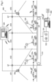
- Fig. 1 schematically shows the transport section of the vehicle 100 from a range AR1 to a range AR5.
- Fig. 1 also shows vehicles 100p, 100q, 100r, 100s, and 1 00t, which are examples of the vehicle 100, and vehicle detectors 80p and 80t, which are examples of the vehicle detector 80.
- the ranges AR1 and AR5 are transport sections where automatic running of the vehicle 100 is performed by remote control.
- the vehicle 100p that has started running from the pre-step runs to the transport device 500 by remote control using the vehicle information acquired from the vehicle detector 80p.
- the range AR5 is a transport section where the vehicle 100t that has been released from the transport system 600 runs to the next step or the like by remote control using the vehicle information acquired from the vehicle detector 80p.
- the ranges AR2 to AR4 are transport sections of the vehicle 100 transported by the transport device 500.
- the range AR2 is the transport starting position where the transport of the vehicle 100 by the transport device 500 is started.
- the transport method of the vehicle 100 is switched from the self-running conveyance by the remote control to the conveyor transport by the transport device 500.
- the vehicle 100p that runs by remote control enters the range AR2 by crossing a starting point SP on one end of the conveyor unit 510.
- the vehicle 100q that has reached the range AR2 becomes ready to be transported by the conveyor unit 510.
- the range AR4 is an area where the transport of the vehicle 100 by the transport device 500 ends.
- the vehicle 100 reaches the range AR4 after the process in the range AR3 is completed.
- the vehicle 100s is detectable by the vehicle detector 80t. That is, self-running conveyance by remote control becomes possible in the range AR4, and the vehicle 100s is allowed to automatically run to be released from the conveyor unit 510.
- the range AR4 is set in advance as the range from an ending point EP at the other end of the conveyor unit 510 to a predetermined distance. This "predetermined distance" is determined, for example, based on the range within which the vehicle detector 80t can detect the vehicle 100t.
- the range AR4 may be any range from the position where the process for the vehicle 100r in the range AR3 is completed to the ending point EP, assuming that the vehicle detector 80t is capable of detecting the vehicle 100t.
- the size of the range AR4 may be varied depending on the progress of the process for the vehicle 100 in the range AR3.
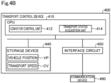
- Fig. 4B is a block diagram showing an internal functional structure of the transport control device 400.
- the transport control device 400 includes a CPU 410 as the central processing unit, the storage device 440, an interface circuit 450, and a transport communication device 490.
- the CPU 410, the storage device 440, and the interface circuit 450 are connected via an internal bus to enable bidirectional communication.
- the interface circuit 450 is connected to the transport communication device 490.
- the transport communication device 490 communicates with the remote control device 300 and the vehicle 100 via a network or the like.
- the storage device 440 is, for example, RAM, ROM, HDD, SSD, or the like.
- a readable/writable region of the storage device 440 stores the transport speed CV detected by the transport speed detector 524 and the vehicle position VP detected by the transport position detector 526.
- the storage device 440 stores a program to implement at least some functions provided in the present embodiment.
- the CPU 410 executes the program to function as a conveyor control unit 412 and a transport status acquisition unit 414.
- the conveyor control unit 412 drives the motor 522 to control turning on/off of the conveyor unit 510 and the transport speed of the conveyor unit 510.
- the transport status acquisition unit 414 acquires transport status information. Specifically, the transport status acquisition unit 414 acquires the position of the vehicle 100, i.e., the vehicle position, in the transport section of the transport by the transport device 500 from the transport position detector 526 and stores it as the vehicle position VP in the storage device 440. The position of the vehicle 100 in the transport section may be acquired using the vehicle detector 80. The transport status acquisition unit 414 acquires the transport speed CV of the vehicle 100 transported by the transport device 500 from the transport speed detector 524, and stores it as the transport speed CV in the storage device 440. If the transport speed and the transport position are not used in the determination as to whether to stop the remote control by the remote control determination unit 316, the transport status acquisition unit 414 may be omitted.
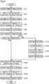
- Fig. 5 is a flowchart showing a transport switching method for the vehicle 100 according to the first embodiment of the present disclosure. This flow is started when the vehicle 100 on which the processing in the pre-step has been completed starts running toward the transport device 500.
- Fig. 1 is referred to as appropriate to facilitate understanding of the technical details.
- the remote control unit 312 causes the vehicle 100p to automatically run toward the transport device 500 by remote control, as shown in the range AR1 in Fig. 1 . More specifically, the remote control unit 312 generates a control command for enabling remote control using the position and orientation of the vehicle 100p estimated by the position estimation unit 314, and transmits the control command to the vehicle 100p.
- the remote control unit 312 causes the vehicle 100p to run beyond the starting point SP of the conveyor unit 510 by remote control using the vehicle information acquired from the vehicle detector 80p.
- the transport control device 400 acquires the vehicle identification information from the vehicle 100p that has arrived at the transport device 500, and confirms whether the acquired vehicle identification information matches the vehicle identification information of the target vehicle for transport in production control. However, the matching may be omitted, and the vehicle information acquisition unit 328 may be omitted if the vehicle identification information is not used.
- the remote control unit 312 causes the vehicle 100 on the conveyor unit 510 to automatically run by remote control to move the vehicle 100 to the range AR2, which is the transport starting position.
- the remote control determination unit 316 determines to stop the remote control.
- the remote control unit 312 drives the lock unit 164 of the vehicle 100 by remote control to switch the function of the power transmission unit 162 to the P range.
- the remote control unit 312 may switch the function of the power transmission unit 162 to the N range instead of switching it to the P range.
- the remote control unit 312 preferably further drives an electric parking brake (EPB) or the like by remote control to ensure that the vehicle 100 is stopped.
- EPB electric parking brake
- the remote control unit 312 stops the remote control of the vehicle 100.
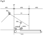
- Fig. 6 is an explanatory view schematically showing a method for stopping remote control at the transport starting position.
- Fig. 6 shows an enlarged view of the transport section of the transport by the transport device 500 near the starting point SP.
- the vehicle 100Q1 runs under remote control by the remote control unit 312, crosses the starting point SP to enter the conveyor unit 510, and reaches the transport starting position.
- the transport starting position is not limited to only a predetermined specific position, but can be set using a predetermined range.
- the transport starting position can be set, for example, using any range included in the transport section of the transport by the transport device 500, assuming that the vehicle 100Q1 can arrive by automatic running under remote control.
- the expression "the vehicle 100Q1 has arrived at the transport starting position" can mean any state as long as the vehicle 100Q1 is ready to be transported by the transport device 500.
- the entire vehicle 100Q1 may not be included in the range AR2, and, for example, a part of the rear side of the vehicle 100Q1 may be deviated from the starting point SP.
- the transport starting position may further be set using a wider range than the range above, considering, for example, errors in the stopping position of the vehicle 100 by remote control. However, in view of reduction in size of the conveyor unit 510, it is preferable that the range of the transport starting position be small. Further, the transport starting position may be set individually for each individual vehicle corresponding to the vehicle identification information, considering the difference in size depending on the vehicle type.
- the transport starting position is set in advance as a range from the starting point SP to a predetermined distance D1.
- the predetermined distance D1 is included, for example, in the transport section of the transport by the transport device 500, and is set in advance based on the range within which the vehicle detector 80p can detect the vehicle 100Q1.
- the transport starting position coincides with the range AR2, and is set as a range that can include the vehicle 100Q1.
- the vehicle 100Q1 that has reached the transport starting position becomes ready to be transported by the conveyor unit 510.
- the remote control determination unit 316 determines to stop the remote control of the vehicle 100Q1.
- whether the vehicle 100Q1 has arrived at the range AR2 can be made using the estimated position of the vehicle 100Q1 relative to the starting point SP in the 3D point cloud data acquired by the vehicle detector 80p.
- whether the vehicle 100Q1 has arrived at the range AR2 may also be made according to results of detection of the presence or absence of the vehicle 100Q1 in the range AR2 by the transport position detector 526 provided in the range AR2.
- the remote control unit 312 drives the lock unit 164 shown in the Fig. 2 by remote control, thereby switching the function of the power transmission unit 162 to the P range.
- the transmission mechanism of the power transmission unit 162 is fixed, thereby stopping the running of the vehicle 100Q1.
- the remote control unit 312 may further turn off the power source of the vehicle 100Q1 or power sources of any units of the vehicle 100Q1.
- the remote control unit 312 switches the vehicle 100Q1 into a state where the running of the vehicle 100Q1 stops, and stops the remote control of the vehicle 100Q1.
- the stopping of the remote control of the vehicle 100q may be achieved by stopping the generation of control commands by the remote control device 300 or by stopping the transmission of control commands to the vehicle 100q.
- the power consumption of the remote control device 300 and the like can be reduced, and also processing burden of the remote control device 300 and other devices mounted on the vehicle 100Q1, such as a control device, can be reduced.
- the power consumption of the vehicle 100Q1 can be reduced by stopping the running of the vehicle 100Q1 during the transport by the transport device 500. Further, by stopping the running of the vehicle 100Q1, for example, workers can smoothly perform inspections on the electrical system, engine compartment, and the like, of the vehicle 100Q1 while the vehicle 100Q1 is being transported.
- the transport control device 400 controls the motor 522 to drive the conveyor unit 510, thereby starting the transport of the vehicle 100.
- the transport instruction unit 322 confirms whether the vehicle 100 is transported by the transport device 500. That is, whether there are any abnormalities in the transport by the transport device 500 is inspected. Whether the vehicle 100 is transported by the transport device 500 can be made by detecting, for example, the presence or absence of the vehicle 100q or 100r acquired by the transport position detector 526 provided in the range AR2 or the range AR3 shown in Fig. 2 , or according to the vehicle information or the like acquired by the vehicle detector 80t.
- the notification unit 324 notifies, for example, that the movement of the vehicle 100 is not detected or that the abnormality countermeasure has been executed.
- the notification unit 324 provides the notification to, for example, workers who perform work on the vehicle 100 on the conveyor unit 510, the manager of the step, or the manager of the transport system 600.
- the transport instruction unit 322 outputs, to the transport control device 400, an instruction to activate the transport device 500 that has been stopped. As a result, the transport of the vehicle 100 by the transport device 500 is started again. If the instruction to decrease the transport speed CV of the vehicle 100 has been output instead of the instruction to stop the transport device 500, the transport instruction unit 322 may output an instruction to restore the decreased transport speed CV to the original transport speed CV to the transport control device 400. To eliminate the delay relative to the target production time, it is also possible to set the transport speed CV to be faster than the transport speed before the restart. Further, the subsequent instruction unit 326 restores the delayed running of the subsequent vehicle to normal running.
- the remote control unit 312 starts the remote control of the vehicle 100 that has reached the area where remote control is possible.
- the remote control unit 312 switches the function of the power transmission unit 162 to the D range by remote control to start the running of the vehicle 100 by remote control. Specifically, the remote control unit 312 drives the lock unit 164 to release the fixed state of the transmission mechanism of the power transmission unit 162, thereby switching the vehicle 100 to be ready for running.
- the remote control device 300 generates a control command for automatic running of the vehicle 100s using the vehicle information acquired from the vehicle detector 80t, and transmits the control command to the vehicle 100s.
- the remote control unit 312 releases the vehicle 100s from the conveyor unit 510 by remote control, and ends the flow. The vehicle 100t that has been released from the transport device 500 is let out to the next step by automatic running.
- the remote control determination unit 316 determines to stop remote control. Causing the vehicle 100 to reach the transport starting position of the transport device 500 and whether the vehicle 100 is disposed at the transport starting position can be performed by the vehicle detector 80, the remote control device 300, and the like, without using the various units of the transport device 500. Therefore, by stopping the remote control at the transport starting position of the transport device 500, the power consumption and the processing burden caused by the remote control device 300 and other devices can be reduced during transport by the transport device 500, thereby efficiently switching the transport method.
- the remote control unit 312 switches to either the N range in which the power from the driving motor 168 is not transmitted to the wheels 166 of the vehicle 100, or to the P range in which the power transmission unit 162 for transmitting power from the driving motor 168 to the wheels 166 is fixed, and then stops the remote control.
- the remote control unit 312 switches to either the N range in which the power from the driving motor 168 is not transmitted to the wheels 166 of the vehicle 100, or to the P range in which the power transmission unit 162 for transmitting power from the driving motor 168 to the wheels 166 is fixed, and then stops the remote control.
- the remote control device 300 of the present embodiment further includes the subsequent instruction unit 326 that outputs an instruction to delay the timing of arrival of the subsequent vehicle scheduled to be transported by the transport device 500 after the vehicle 100, at the transport device 500, if the vehicle 100 is not transported by the transport device 500 after the remote control is stopped. It is possible to prevent the subsequent vehicle from colliding with the vehicle 100 that has not started to be transported by the transport device 500 and is stopped at the transport starting position.
- the remote control device 300 of the present embodiment further includes the notification unit 324 that provides notification when the vehicle 100 is not transported by the transport device 500 after the remote control is stopped.
- the abnormality countermeasures to address the abnormalities in the transport by the transport device 500 can be taken into action quickly, thereby facilitating quick restoration of the transport device 500.
- Fig. 7 is a flowchart showing a transport method for the vehicle 100 according to the second embodiment.
- the transport method of the present embodiment differs from the transport method according to the first embodiment shown in Fig. 5 in that the step S40 and the step S230 are omitted in the present embodiment.
- the first embodiment described above shows an example in which, when the remote control determination unit 316 determines to stop the remote control, the function of the power transmission unit 162 is switched to the P range, and then the remote control is stopped.
- the remote control may be stopped without switching the function of the power transmission unit 162, as in the present embodiment.
- the transport method of the present embodiment differs from the transport method of the first embodiment in that the processes from the step S100 to the step S140 are omitted in the present embodiment.
- the first embodiment described above shows an example in which abnormality countermeasures from the step S110 to the step S140 are executed when the vehicle 100 is not transported by the transport device 500 after the remote control is stopped.
- the processes from the step S100 to the step S140 may be omitted so that the abnormality countermeasures are not executed.
- any one of the abnormality countermeasures including an action of stopping the transport device 500, notification by the notification unit 324, and output of an instruction to delay the arrival timing of the subsequent vehicle, or any combination of these abnormality countermeasures, may be executed.
- the transport method of the present embodiment differs from the transport method of the first embodiment in that the step S300 to the step S340 are provided after the step S30 in the present embodiment. Specifically, when the remote control determination unit 316 determines to stop the remote control in the step S30, the remote control determination unit 316 forwards the process to the step S300. In the step S300, the remote control determination unit 316 further confirms the transport speed CV of the vehicle 100 transported by the transport device 500, and compares the transport speed CV with the reference speed SV. If the confirmed transport speed CV is slower than the reference speed SV (S300: YES), the remote control unit 312 forwards the process to the step S50.
- the remote control determination unit 316 determines to stop the remote control in the step S30
- the remote control determination unit 316 forwards the process to the step S300.
- the remote control determination unit 316 further confirms the transport speed CV of the vehicle 100 transported by the transport device 500, and compares the transport speed CV with the reference speed SV. If the confirmed transport speed CV is slower than
- the remote control unit 312 may confirm the transport time instead of confirming the transport speed CV, and may forward the process to the step S50 when the transport time is longer than a reference transport time.
- the remote control unit 312 stops the remote control of the vehicle 100 in the same method as that in the first embodiment described above. More specifically, the remote control unit 312 stops the movement of the vehicle 100 not by turning off the power source of the vehicle 100 but by stopping the generation of control commands for enabling remote control of the vehicle 100 or stopping the transmission of the generated control commands to the vehicle 100.
- the remote control unit 312 forwards the process to the step S310 to turn off the power source of the vehicle 100 by remote control.
- "Turning off the power source of the vehicle 100” means turning off the ignition or the engine of the vehicle 100.
- the remote control unit 312 stops the remote control of the vehicle 100.
- the stopping of the remote control may be achieved by turning off the power source of the vehicle 100 in the step S320, or, as in the first embodiment described above, by stopping the generation of control commands for enabling remote control of the vehicle 100 or stopping the transmission of the generated control commands to the vehicle 100 by the remote control unit 312.
- the transport control device 400 controls the motor 522 to drive the conveyor unit 510, thereby starting the transport of the vehicle 100.
- the vehicle 100 is transported by the transport device 500 and reaches the remote control preparation starting position.
- the "remote control preparation starting position” is the position where the preparation to enable remote control at a predetermined position is started.
- the "predetermined position” is any position within the range AR4, and the preparation starting position is a position included in the range AR3.
- the fact that the vehicle 100 has reached the preparation starting position can be detected by the transport position detector 526 provided in the range AR3, etc. The same detection may be done by the vehicle detector 80 if the vehicle detector 80 is provided in the range AR3.
- the remote control unit 312 turns on the power source of the vehicle 100 and starts preparing for remote control by initiating control of various units of the vehicle 100 and the remote control device 300. By the time the vehicle 100 reaches the area where the vehicle 100 can be transported by remote control, the preparation for the remote control is completed, enabling the remote control unit 312 to start the remote control of the vehicle 100.
- the remote control determination unit 316 determines to stop the remote control, the remote control determination unit 316 further confirms the transport speed CV of the vehicle 100 transported by the transport device 500. If the confirmed transport speed CV is slower than the predetermined reference speed SV, the remote control unit 312 turns off the power source of the vehicle 100 and then stops the remote control. If the transport speed CV is equal to or greater than the reference speed SV, the remote control is stopped without turning off the power source of the vehicle 100.
- the transport time of the transport by the transport device 500 is long enough to provide sufficient preparation time to restart the remote control, the power source of the vehicle 100 is turned off to reduce power consumption of the vehicle 100, and, if the transport time is short and the preparation time to restart the remote control is short, it is possible to rapidly restart the remote control by stopping the remote control of the vehicle 100 in a simple manner instead of turning off the power source of the vehicle 100. In this way, the remote control can be stopped in a state suitable for each transport time of the transport by the transport device 500.
- each of the embodiments described above shows an example in which the remote control determination unit 316 and the driving control determination unit 216 estimate the position of the vehicle 100 using the vehicle information detected by the vehicle detector 80, and determine to stop the remote control when the acquired estimated position reaches the transport starting position.
- the remote control determination unit 316 and the driving control determination unit 216 may determine to stop the remote control when, instead of the estimated position, the position of the vehicle 100 in the transport section that is detected by the transport position detector 526 or the like reaches the transport starting position.
- the learning dataset contains a plurality of training images including the vehicle 100, and a label showing whether each region in the training image is a region indicating the vehicle 100 or a region indicating a subject other than the vehicle 100, for example,
- a parameter for the CNN is preferably updated through backpropagation in such a manner as to reduce error between output result obtained by the detection model and the label.
- the vehicle 100 is simply required to have a configuration to become movable by unmanned driving.
- the vehicle 100 may embodied as a platform having the following configuration, for example.
- the vehicle 100 is simply required to include at least actuators and the ECU 200 as a controller. More specifically, in order to fulfill three functions including "run,” “turn,” and “stop” by unmanned driving, the actuators may include a driving device, a steering device and a braking device. The actuators are controlled by the controller that controls running of the vehicle 100. In order for the vehicle 100 to acquire information from outside for unmanned driving, the vehicle 100 is simply required to include the vehicle communication device 190 further.
- the vehicle 100 to become movable by unmanned driving is not required to be equipped with at least some of interior components such as a driver's seat and a dashboard, is not required to be equipped with at least some of exterior components such as a bumper and a fender or is not required to be equipped with a bodyshell.
- a remaining component such as a bodyshell may be mounted on the vehicle 100 before the vehicle 100 is shipped from a factory, or a remaining component such as a bodyshell may be mounted on the vehicle 100 after the vehicle 100 is shipped from a factory while the remaining component such as a bodyshell is not mounted on the vehicle 100.
- Each of components may be mounted on the vehicle 100 from any direction such as from above, from below, from the front, from the back, from the right, or from the left. Alternatively, these components may be mounted from the same direction or from respective different directions.
- the location determination for the platform may be performed in the same way as for the vehicle 100 in the first embodiments.
- modules may include an arbitrary exterior component such as a bumper or a grill, or an arbitrary interior component such as a seat or a console.
- vehicle 100 not also any types of moving object may be manufactured by combining a plurality of modules.
- a module may be manufactured by joining a plurality of components by welding or using a fixture, for example, or may be manufactured by forming at least part of the module integrally as a single component by casting.
- a process of forming at least part of a module as a single component is also called Giga-casting or Mega-casting.
- Giga-casting can form each part conventionally formed by joining multiple parts in a moving object as a single component.
- the front module, the center module, or the rear module described above may be manufactured using Giga-casting, for example.
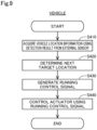
- the remote control device 300 performs the processing from acquisition of vehicle location information to generation of a running control signal.
- the vehicle 100 may perform at least part of the processing from acquisition of vehicle location information to generation of a running control signal.
- embodiments (1) to (3) described below are applicable, for example.
- the remote control device 300 may acquire vehicle location information, determine a target location to which the vehicle 100 is to move next, and generate a route from a current location of the vehicle 100 indicated by the acquired vehicle location information to the target location.
- the remote control device 300 may generate a route to the target location between the current location and a destination or generate a route to the destination.
- the remote control device 300 may transmit the generated route to the vehicle 100.
- the vehicle 100 may generate a running control signal in such a manner as to cause the vehicle 100 to run along the route received from the remote control device 300 and control the actuator 140 using the generated running control signal.
- the remote control device 300 may acquire vehicle location information and transmit the acquired vehicle location information to the vehicle 100.
- the vehicle 100 may determine a target location to which the vehicle 100 is to move next, generate a route from a current location of the vehicle 100 indicated by the received vehicle location information to the target location, generate a running control signal in such a manner as to cause the vehicle 100 to run along the generated route, and control the actuator 140 using the generated running control signal.
- an internal sensor may be mounted on the vehicle 100, and detection result output from the internal sensor may be used in at least one of the generation of the route and the generation of the running control signal.
- the internal sensor is a sensor mounted on the vehicle 100. More specifically, the internal sensor might include a camera, LiDAR, a millimeter wave radar, an ultrasonic wave sensor, a GPS sensor, an acceleration sensor, and a gyroscopic sensor, for example.
- the remote control device 300 may acquire detection result from the internal sensor, and in generating the route, may reflect the detection result from the internal sensor in the route.
- the vehicle 100 may acquire detection result from the internal sensor, and in generating the running control signal, may reflect the detection result from the internal sensor in the running control signal.
- the vehicle 100 may acquire detection result from the internal sensor, and in generating the route, may reflect the detection result from the internal sensor in the route.
- the vehicle 100 may acquire detection result from the internal sensor, and in generating the running control signal, may reflect the detection result from the internal sensor in the running control signal.
- the vehicle 100 may be equipped with an internal sensor, and detection result output from the internal sensor may be used in at least one of generation of a route and generation of a running control signal.
- the vehicle 100 may acquire detection result from the internal sensor, and in generating the route, may reflect the detection result from the internal sensor in the route.
- the vehicle 100 may acquire detection result from the internal sensor, and in generating the running control signal, may reflect the detection result from the internal sensor in the running control signal.
- the vehicle 100 acquires the position and orientation of the vehicle 100 using the detection result of the vehicle detector 80.
- the vehicle 100 may be equipped with an internal sensor, the vehicle 100 may acquire vehicle location information using detection result from the internal sensor, determine a target location to which the vehicle 100 is to move next, generate a route from a current location of the vehicle 100 indicated by the acquired vehicle location information to the target location, generate a running control signal for running along the generated route, and control the actuator 140 of the vehicle 100 using the generated running control signal.
- the vehicle 100 is capable of running without using any detection result from the vehicle detector 80.
- the vehicle 100 may acquire target arrival time or traffic congestion information from outside the vehicle 100 and reflect the target arrival time or traffic congestion information in at least one of the route and the running control signal.
- the functional configuration of the transport system 600 may be entirely provided at the vehicle 100. Specifically, the processes realized by the transport system 600 in the present disclosure may be realized by the vehicle 100 alone. Further, all of the structures of the transport system 600 and the functional structures of the remote control device 300 may be provided in the vehicle 100. In other words, the processes implemented by the transport system 600 and the remote control device 300 shown in the present disclosure may be implemented by the vehicle 100 alone.
Landscapes
- Engineering & Computer Science (AREA)
- Physics & Mathematics (AREA)
- General Physics & Mathematics (AREA)
- Remote Sensing (AREA)
- Radar, Positioning & Navigation (AREA)
- Electromagnetism (AREA)
- Automation & Control Theory (AREA)
- Aviation & Aerospace Engineering (AREA)
- Computer Networks & Wireless Communication (AREA)
- Mechanical Engineering (AREA)
- Transportation (AREA)
- Combustion & Propulsion (AREA)
- Chemical & Material Sciences (AREA)
- Manufacturing & Machinery (AREA)
- Human Computer Interaction (AREA)
- Control Of Position, Course, Altitude, Or Attitude Of Moving Bodies (AREA)
- Automobile Manufacture Line, Endless Track Vehicle, Trailer (AREA)
Applications Claiming Priority (1)
| Application Number | Priority Date | Filing Date | Title |
|---|---|---|---|
| JP2023145728A JP7768202B2 (ja) | 2023-09-08 | 2023-09-08 | 搬送方法切替装置、搬送切替方法、および車両 |
Publications (3)
| Publication Number | Publication Date |
|---|---|
| EP4521187A1 true EP4521187A1 (de) | 2025-03-12 |
| EP4521187C0 EP4521187C0 (de) | 2025-12-24 |
| EP4521187B1 EP4521187B1 (de) | 2025-12-24 |
Family
ID=92142142
Family Applications (1)
| Application Number | Title | Priority Date | Filing Date |
|---|---|---|---|
| EP24191734.3A Active EP4521187B1 (de) | 2023-09-08 | 2024-07-30 | Vorrichtung zum umschalten des transportverfahrens eines beweglichen objekts und verfahren dazu |
Country Status (4)
| Country | Link |
|---|---|
| US (1) | US20250085711A1 (de) |
| EP (1) | EP4521187B1 (de) |
| JP (1) | JP7768202B2 (de) |
| CN (1) | CN119590813A (de) |
Citations (2)
| Publication number | Priority date | Publication date | Assignee | Title |
|---|---|---|---|---|
| US20170320529A1 (en) * | 2014-11-26 | 2017-11-09 | Robert Bosch Gmbh | Method for operating a vehicle and for operating a manufacturing system |
| JP2021062790A (ja) * | 2019-10-16 | 2021-04-22 | トヨタ自動車株式会社 | 車両の移送システム |
Family Cites Families (3)
| Publication number | Priority date | Publication date | Assignee | Title |
|---|---|---|---|---|
| JPS63112290A (ja) * | 1986-10-29 | 1988-05-17 | Honda Motor Co Ltd | 同期作業装置 |
| JPH08141945A (ja) * | 1994-11-22 | 1996-06-04 | Himu Kenkyusho:Kk | 作業ロボット導入生産システム |
| DE102006026132A1 (de) | 2006-06-03 | 2007-06-21 | Daimlerchrysler Ag | Bearbeitungssystem für ein bewegtes Werkstück und Verfahren zum Positionieren des Bearbeitungssystems |
-
2023
- 2023-09-08 JP JP2023145728A patent/JP7768202B2/ja active Active
-
2024
- 2024-07-23 US US18/781,490 patent/US20250085711A1/en active Pending
- 2024-07-30 EP EP24191734.3A patent/EP4521187B1/de active Active
- 2024-08-29 CN CN202411203182.2A patent/CN119590813A/zh active Pending
Patent Citations (2)
| Publication number | Priority date | Publication date | Assignee | Title |
|---|---|---|---|---|
| US20170320529A1 (en) * | 2014-11-26 | 2017-11-09 | Robert Bosch Gmbh | Method for operating a vehicle and for operating a manufacturing system |
| JP2021062790A (ja) * | 2019-10-16 | 2021-04-22 | トヨタ自動車株式会社 | 車両の移送システム |
Also Published As
| Publication number | Publication date |
|---|---|
| CN119590813A (zh) | 2025-03-11 |
| EP4521187C0 (de) | 2025-12-24 |
| JP7768202B2 (ja) | 2025-11-12 |
| US20250085711A1 (en) | 2025-03-13 |
| JP2025039007A (ja) | 2025-03-21 |
| EP4521187B1 (de) | 2025-12-24 |
Similar Documents
| Publication | Publication Date | Title |
|---|---|---|
| US20240393362A1 (en) | Inspection method of inspecting moving object | |
| EP4521180A2 (de) | Zustandswechselvorrichtung, bewegliches objekt und herstellungsverfahren für ein bewegliches objekt | |
| US20240317340A1 (en) | Control system, server, and vehicle | |
| EP4439515B1 (de) | Fernbedienungssystem, fernbedienungs-deaktivierungseinrichtung und fernbedienungs-deaktivierungsverfahren | |
| US20240402711A1 (en) | Moving object, remote control system, and remote control method | |
| US20240393256A1 (en) | Inspection method of inspecting moving object | |
| US20240393211A1 (en) | Inspection method of inspecting moving object | |
| EP4521187B1 (de) | Vorrichtung zum umschalten des transportverfahrens eines beweglichen objekts und verfahren dazu | |
| EP4521186A1 (de) | Transportverfahrenumschaltvorrichtung, transportumschaltverfahren und bewegliches objekt | |
| EP4521188A1 (de) | Fahrzeugdetektionsvorrichtung, fahrzeugdetektionsverfahren und fahrzeug | |
| EP4439516A1 (de) | Bewegliches objekt, fernbedienungs-deaktivierungssystem und fernbedienungs-deaktivierungsverfahren | |
| US20240326940A1 (en) | Moving object, remote control deactivation system, and remote control deactivation method | |
| US20250271855A1 (en) | Apparatus, moving object, and method of producing moving object | |
| US12603003B2 (en) | Control device and unmanned driving method | |
| EP4478319B1 (de) | Ferngesteuerte entwertungsvorrichtung und sich bewegendes objekt | |
| US20250269920A1 (en) | Apparatus, moving object, and method for producing moving object | |
| US20250155878A1 (en) | System, device, and method | |
| EP4471529A1 (de) | Steuerungsvorrichtung und steuerungsverfahren | |
| US20250256793A1 (en) | System, assembly device, and moving object | |
| US20250147521A1 (en) | Control system, mobile object, and control method | |
| US20240329644A1 (en) | Unmanned driving system, control device, and unmanned driving method | |
| EP4471527A1 (de) | Steuerungsvorrichtung, bewegliches objekt und steuerungsverfahren | |
| US20250291341A1 (en) | Server device and vehicle | |
| US20250170605A1 (en) | Control device and control method | |
| US20240327122A1 (en) | Unmanned driving system, control device, and unmanned driving method |
Legal Events
| Date | Code | Title | Description |
|---|---|---|---|
| PUAI | Public reference made under article 153(3) epc to a published international application that has entered the european phase |
Free format text: ORIGINAL CODE: 0009012 |
|
| STAA | Information on the status of an ep patent application or granted ep patent |
Free format text: STATUS: REQUEST FOR EXAMINATION WAS MADE |
|
| 17P | Request for examination filed |
Effective date: 20240730 |
|
| AK | Designated contracting states |
Kind code of ref document: A1 Designated state(s): AL AT BE BG CH CY CZ DE DK EE ES FI FR GB GR HR HU IE IS IT LI LT LU LV MC ME MK MT NL NO PL PT RO RS SE SI SK SM TR |
|
| GRAP | Despatch of communication of intention to grant a patent |
Free format text: ORIGINAL CODE: EPIDOSNIGR1 |
|
| STAA | Information on the status of an ep patent application or granted ep patent |
Free format text: STATUS: GRANT OF PATENT IS INTENDED |
|
| INTG | Intention to grant announced |
Effective date: 20251001 |
|
| GRAS | Grant fee paid |
Free format text: ORIGINAL CODE: EPIDOSNIGR3 |
|
| GRAA | (expected) grant |
Free format text: ORIGINAL CODE: 0009210 |
|
| STAA | Information on the status of an ep patent application or granted ep patent |
Free format text: STATUS: THE PATENT HAS BEEN GRANTED |
|
| AK | Designated contracting states |
Kind code of ref document: B1 Designated state(s): AL AT BE BG CH CY CZ DE DK EE ES FI FR GB GR HR HU IE IS IT LI LT LU LV MC ME MK MT NL NO PL PT RO RS SE SI SK SM TR |
|
| REG | Reference to a national code |
Ref country code: CH Ref legal event code: F10 Free format text: ST27 STATUS EVENT CODE: U-0-0-F10-F00 (AS PROVIDED BY THE NATIONAL OFFICE) Effective date: 20251224 Ref country code: GB Ref legal event code: FG4D |
|
| REG | Reference to a national code |
Ref country code: DE Ref legal event code: R096 Ref document number: 602024001820 Country of ref document: DE |
|
| U01 | Request for unitary effect filed |
Effective date: 20260120 |
|
| U07 | Unitary effect registered |
Designated state(s): AT BE BG DE DK EE FI FR IT LT LU LV MT NL PT RO SE SI Effective date: 20260123 |
|
| PG25 | Lapsed in a contracting state [announced via postgrant information from national office to epo] |
Ref country code: NO Free format text: LAPSE BECAUSE OF FAILURE TO SUBMIT A TRANSLATION OF THE DESCRIPTION OR TO PAY THE FEE WITHIN THE PRESCRIBED TIME-LIMIT Effective date: 20260324 |
|
| PG25 | Lapsed in a contracting state [announced via postgrant information from national office to epo] |
Ref country code: HR Free format text: LAPSE BECAUSE OF FAILURE TO SUBMIT A TRANSLATION OF THE DESCRIPTION OR TO PAY THE FEE WITHIN THE PRESCRIBED TIME-LIMIT Effective date: 20251224 |
|
| PG25 | Lapsed in a contracting state [announced via postgrant information from national office to epo] |
Ref country code: RS Free format text: LAPSE BECAUSE OF FAILURE TO SUBMIT A TRANSLATION OF THE DESCRIPTION OR TO PAY THE FEE WITHIN THE PRESCRIBED TIME-LIMIT Effective date: 20260324 |