EP4521171A1 - Image forming apparatus, image forming system, image forming method, and carrier medium - Google Patents
Image forming apparatus, image forming system, image forming method, and carrier medium Download PDFInfo
- Publication number
- EP4521171A1 EP4521171A1 EP24194508.8A EP24194508A EP4521171A1 EP 4521171 A1 EP4521171 A1 EP 4521171A1 EP 24194508 A EP24194508 A EP 24194508A EP 4521171 A1 EP4521171 A1 EP 4521171A1
- Authority
- EP
- European Patent Office
- Prior art keywords
- printing
- image forming
- recording medium
- forming device
- print data
- Prior art date
- Legal status (The legal status is an assumption and is not a legal conclusion. Google has not performed a legal analysis and makes no representation as to the accuracy of the status listed.)
- Pending
Links
- 238000000034 method Methods 0.000 title claims description 32
- 230000007246 mechanism Effects 0.000 claims abstract description 111
- 230000008859 change Effects 0.000 claims description 15
- 238000010586 diagram Methods 0.000 description 22
- 230000008569 process Effects 0.000 description 16
- 239000000463 material Substances 0.000 description 14
- 230000006870 function Effects 0.000 description 5
- 230000012447 hatching Effects 0.000 description 5
- 239000003086 colorant Substances 0.000 description 3
- 230000018109 developmental process Effects 0.000 description 3
- 230000015572 biosynthetic process Effects 0.000 description 2
- 239000007788 liquid Substances 0.000 description 2
- 230000003287 optical effect Effects 0.000 description 2
- 230000001052 transient effect Effects 0.000 description 2
- 230000005540 biological transmission Effects 0.000 description 1
- 238000004040 coloring Methods 0.000 description 1
- 239000012050 conventional carrier Substances 0.000 description 1
- 230000003247 decreasing effect Effects 0.000 description 1
- 230000002708 enhancing effect Effects 0.000 description 1
- PCHJSUWPFVWCPO-UHFFFAOYSA-N gold Chemical compound [Au] PCHJSUWPFVWCPO-UHFFFAOYSA-N 0.000 description 1
- 229910052737 gold Inorganic materials 0.000 description 1
- 239000010931 gold Substances 0.000 description 1
- 229910052736 halogen Inorganic materials 0.000 description 1
- 150000002367 halogens Chemical class 0.000 description 1
- 238000010438 heat treatment Methods 0.000 description 1
- 238000003384 imaging method Methods 0.000 description 1
- 230000006872 improvement Effects 0.000 description 1
- 230000010365 information processing Effects 0.000 description 1
- 239000004973 liquid crystal related substance Substances 0.000 description 1
- 239000000203 mixture Substances 0.000 description 1
- 238000003825 pressing Methods 0.000 description 1
- 230000004044 response Effects 0.000 description 1
- 229910052709 silver Inorganic materials 0.000 description 1
- 239000004332 silver Substances 0.000 description 1
- 239000007787 solid Substances 0.000 description 1
- 230000000087 stabilizing effect Effects 0.000 description 1
Images






Classifications
-
- G—PHYSICS
- G03—PHOTOGRAPHY; CINEMATOGRAPHY; ANALOGOUS TECHNIQUES USING WAVES OTHER THAN OPTICAL WAVES; ELECTROGRAPHY; HOLOGRAPHY
- G03G—ELECTROGRAPHY; ELECTROPHOTOGRAPHY; MAGNETOGRAPHY
- G03G15/00—Apparatus for electrographic processes using a charge pattern
- G03G15/36—Editing, i.e. producing a composite image by copying one or more original images or parts thereof
-
- H—ELECTRICITY
- H04—ELECTRIC COMMUNICATION TECHNIQUE
- H04N—PICTORIAL COMMUNICATION, e.g. TELEVISION
- H04N1/00—Scanning, transmission or reproduction of documents or the like, e.g. facsimile transmission; Details thereof
- H04N1/32—Circuits or arrangements for control or supervision between transmitter and receiver or between image input and image output device, e.g. between a still-image camera and its memory or between a still-image camera and a printer device
- H04N1/32101—Display, printing, storage or transmission of additional information, e.g. ID code, date and time or title
- H04N1/32144—Display, printing, storage or transmission of additional information, e.g. ID code, date and time or title embedded in the image data, i.e. enclosed or integrated in the image, e.g. watermark, super-imposed logo or stamp
- H04N1/32149—Methods relating to embedding, encoding, decoding, detection or retrieval operations
- H04N1/32309—Methods relating to embedding, encoding, decoding, detection or retrieval operations in colour image data
-
- G—PHYSICS
- G03—PHOTOGRAPHY; CINEMATOGRAPHY; ANALOGOUS TECHNIQUES USING WAVES OTHER THAN OPTICAL WAVES; ELECTROGRAPHY; HOLOGRAPHY
- G03G—ELECTROGRAPHY; ELECTROPHOTOGRAPHY; MAGNETOGRAPHY
- G03G15/00—Apparatus for electrographic processes using a charge pattern
- G03G15/50—Machine control of apparatus for electrographic processes using a charge pattern, e.g. regulating differents parts of the machine, multimode copiers, microprocessor control
- G03G15/5029—Machine control of apparatus for electrographic processes using a charge pattern, e.g. regulating differents parts of the machine, multimode copiers, microprocessor control by measuring the copy material characteristics, e.g. weight, thickness
-
- G—PHYSICS
- G03—PHOTOGRAPHY; CINEMATOGRAPHY; ANALOGOUS TECHNIQUES USING WAVES OTHER THAN OPTICAL WAVES; ELECTROGRAPHY; HOLOGRAPHY
- G03G—ELECTROGRAPHY; ELECTROPHOTOGRAPHY; MAGNETOGRAPHY
- G03G15/00—Apparatus for electrographic processes using a charge pattern
- G03G15/50—Machine control of apparatus for electrographic processes using a charge pattern, e.g. regulating differents parts of the machine, multimode copiers, microprocessor control
- G03G15/5062—Machine control of apparatus for electrographic processes using a charge pattern, e.g. regulating differents parts of the machine, multimode copiers, microprocessor control by measuring the characteristics of an image on the copy material
-
- H—ELECTRICITY
- H04—ELECTRIC COMMUNICATION TECHNIQUE
- H04N—PICTORIAL COMMUNICATION, e.g. TELEVISION
- H04N1/00—Scanning, transmission or reproduction of documents or the like, e.g. facsimile transmission; Details thereof
- H04N1/00567—Handling of original or reproduction media, e.g. cutting, separating, stacking
- H04N1/0057—Conveying sheets before or after scanning
- H04N1/00572—Conveying sheets before or after scanning with refeeding for double-sided scanning, e.g. using one scanning head for both sides of a sheet
-
- H—ELECTRICITY
- H04—ELECTRIC COMMUNICATION TECHNIQUE
- H04N—PICTORIAL COMMUNICATION, e.g. TELEVISION
- H04N1/00—Scanning, transmission or reproduction of documents or the like, e.g. facsimile transmission; Details thereof
- H04N1/46—Colour picture communication systems
- H04N1/48—Picture signal generators
- H04N1/482—Picture signal generators using the same detector device sequentially for different colour components
-
- G—PHYSICS
- G03—PHOTOGRAPHY; CINEMATOGRAPHY; ANALOGOUS TECHNIQUES USING WAVES OTHER THAN OPTICAL WAVES; ELECTROGRAPHY; HOLOGRAPHY
- G03G—ELECTROGRAPHY; ELECTROPHOTOGRAPHY; MAGNETOGRAPHY
- G03G15/00—Apparatus for electrographic processes using a charge pattern
- G03G15/01—Apparatus for electrographic processes using a charge pattern for producing multicoloured copies
- G03G15/0142—Structure of complete machines
- G03G15/0178—Structure of complete machines using more than one reusable electrographic recording member, e.g. one for every monocolour image
- G03G15/0189—Structure of complete machines using more than one reusable electrographic recording member, e.g. one for every monocolour image primary transfer to an intermediate transfer belt
-
- G—PHYSICS
- G03—PHOTOGRAPHY; CINEMATOGRAPHY; ANALOGOUS TECHNIQUES USING WAVES OTHER THAN OPTICAL WAVES; ELECTROGRAPHY; HOLOGRAPHY
- G03G—ELECTROGRAPHY; ELECTROPHOTOGRAPHY; MAGNETOGRAPHY
- G03G15/00—Apparatus for electrographic processes using a charge pattern
- G03G15/22—Apparatus for electrographic processes using a charge pattern involving the combination of more than one step according to groups G03G13/02 - G03G13/20
- G03G15/23—Apparatus for electrographic processes using a charge pattern involving the combination of more than one step according to groups G03G13/02 - G03G13/20 specially adapted for copying both sides of an original or for copying on both sides of a recording or image-receiving material
- G03G15/231—Arrangements for copying on both sides of a recording or image-receiving material
- G03G15/232—Arrangements for copying on both sides of a recording or image-receiving material using a single reusable electrographic recording member
- G03G15/234—Arrangements for copying on both sides of a recording or image-receiving material using a single reusable electrographic recording member by inverting and refeeding the image receiving material with an image on one face to the recording member to transfer a second image on its second face, e.g. by using a duplex tray; Details of duplex trays or inverters
-
- G—PHYSICS
- G03—PHOTOGRAPHY; CINEMATOGRAPHY; ANALOGOUS TECHNIQUES USING WAVES OTHER THAN OPTICAL WAVES; ELECTROGRAPHY; HOLOGRAPHY
- G03G—ELECTROGRAPHY; ELECTROPHOTOGRAPHY; MAGNETOGRAPHY
- G03G2215/00—Apparatus for electrophotographic processes
- G03G2215/00362—Apparatus for electrophotographic processes relating to the copy medium handling
- G03G2215/00535—Stable handling of copy medium
- G03G2215/00556—Control of copy medium feeding
- G03G2215/00578—Composite print mode
Definitions
- the present disclosure relates to an image forming apparatus, an image forming system, an image forming method, and a carrier medium.
- Some known image forming apparatuses include an image forming device to form an image on a sheet, an image forming passage to convey a sheet to the image forming device, and a reverse passage to reverse the sheet and cause the reversed sheet to enter the image forming passage (for example, see Japanese Patent No. 6981066 ).
- the reverse passage includes a switchback portion that causes the sheet to travel in the reverse direction.
- the image forming apparatus described in Japanese Patent No. 6981066 further includes a shortcut passage to cause the sheet to return to the image forming passage without passing through the switchback portion. With this configuration, the image forming apparatus can convey the sheet to the image forming device such that images are formed on the same side of the sheet.
- Japanese Patent No. 6981066 does not teach or suggest how to form images on the same side of the sheet. In Japanese Patent No. 6981066 , there is room for improvement in the color quality of images formed on a medium.
- an image forming apparatus includes an image forming device, a first conveyance mechanism, a second conveyance mechanism, and a control unit.
- the image forming device forms an image on a recording medium.
- the first conveyance mechanism conveys the recording medium to the image forming device.
- the second conveyance mechanism conveys the recording medium having passed through the image forming device to the image forming device again.
- the control unit controls multiple times of printing operations of the image forming device.
- the image forming device performs multiple times of printing on a same side of the recording medium.
- the multiple times of printing include first printing and second printing.
- the first printing is printing on the recording medium based on first print data.
- the second printing is printing on the recording medium subjected to the first printing based on second print data different from the first print data.
- an image forming system for printing multiple times on a same side of a recording medium with an image forming device includes a first conveyance mechanism, a second conveyance mechanism, and a control unit.
- the first conveyance mechanism conveys the recording medium to the image forming device.
- the second conveyance mechanism conveys the recording medium having passed through the image forming device to the image forming device again.
- the control unit controls multiple times of printing operations of the image forming device.
- the control unit controls operations of the first conveyance mechanism, the second conveyance mechanism, and the image forming device to cause the image forming device to perform first printing on the recording medium based on first print data and perform second printing on the recording medium subjected to the first printing based on second print data different from the first print data.
- an image forming method for printing multiple times on a same side of a recording medium with an image forming device includes first conveying the recording medium to the image forming device, second conveying the recording medium having passed through the image forming device to the image forming device again, and controlling multiple times of printing operations of the image forming device.
- the controlling includes causing the image forming device to perform first printing on the recording medium based on first print data and perform second printing on the recording medium subjected to the first printing based on second print data different from the first print data.
- a carrier medium carries computer-readable code for controlling a computer system to carry out a method for printing multiple times on a same side of a recording medium with an image forming device.
- the method includes first conveying the recording medium to the image forming device, second conveying the recording medium having passed through the image forming device to the image forming device again, and controlling multiple times of printing operations of the image forming device.
- the controlling includes causing the image forming device to perform first printing on the recording medium based on first print data and perform second printing on the recording medium subjected to the first printing based on second print data different from the first print data.
- an image forming apparatus that enhances the color quality of an image.
- FIG. 1 is a schematic diagram illustrating a configuration of the image forming apparatus 100 according to an embodiment of the present disclosure.
- the image forming apparatus 100 is an electrophotographic tandem-type color image forming apparatus.
- the image forming apparatus 100 includes sheet feeding devices 10A and 10B, a first conveyance mechanism 20, an image forming device 30, a fixing device 33, a sheet ejection device 40, and a second conveyance mechanism 50.
- the image forming device 30 includes an intermediate transfer belt 35, multiple drum-shaped photoconductors 34K, 34C, 34M, 34Y, and 34S facing the intermediate transfer belt 35, and a transfer unit 32.
- the image forming device 30 forms a full-color image on a recording medium supplied from the sheet feeding device 10A or 10B and the first conveyance mechanism 20, the first conveyance mechanism 20 conveys the recording medium bearing the full-color image and ejects the recording medium to the sheet ejection device 40.
- FIGS. 2A and 2B are plan views of example front and back sides of a recording medium 2.
- FIG. 2A is a plan view of a front side 2a of the recording medium 2.
- FIG. 2B is a plan view of a back side 2b of the recording medium 2.
- the recording medium 2 is a sheet-shaped recording medium 2 having a predetermined thickness.
- the back side 2b is an opposite side of the front side 2a in the thickness direction of the recording medium 2.
- the front side 2a is an example of a first side of the recording medium.
- the back side 2b may be a second side of the recording medium.
- the recording medium 2 may be, for example, a sheet or a transparent film.
- the sheet may be, for example, a white sheet or a black sheet.
- the color of the sheet may be another color such as yellow, pink, or blue.
- the recording medium 2 may be a medium other than the sheet and the transparent film.
- the sheet feeding devices 10A and 10B are trays that hold the recording media 2.
- the sheet feeding devices 10A and 10B hold different types of recording media 2 from each other.
- the different types of recording media 2 include different materials or different colors.
- the sheet feeding device 10A holds the recording media 2 such as white sheets.
- the sheet feeding device 10B holds the recording media 2 such as black sheets.
- the image forming apparatus 100 may include sheet feeding devices that hold three or more types of recording media 2 or may include a sheet feeding device that holds one type of recording media 2.
- the first conveyance mechanism 20 is a conveyance mechanism that supplies the recording media 2 held in the sheet feeding devices 10A and 10B to the transfer unit 32.
- the first conveyance mechanism 20 includes a conveyance mechanism that conveys the recording medium 2 having passed the transfer unit 32 of the image forming device 30.
- the recording medium 2 having passed the transfer unit 32 is sent to the sheet ejection device 40 or the second conveyance mechanism 50 in a subsequent stage.
- the first conveyance mechanism 20 includes conveyance roller pairs 22 that convey the recording medium 2.
- the first conveyance mechanism 20 includes a guide that guides the conveyance of the recording medium 2.
- the image forming device 30 includes the transfer unit 32.
- the transfer unit 32 includes the drum-shaped photoconductors 34K, 34C, 34M, 34Y, and 34S, the intermediate transfer belt 35, and a secondary transfer roller 36.
- the intermediate transfer belt 35 is an endless belt on which an intermediate transfer image is formed.
- the intermediate transfer belt 35 rotates.
- the drum-shaped photoconductors 34K, 34C, 34M, 34Y, and 34S are arranged in this order in a direction in which the intermediate transfer belt 35 rotates.
- the drum-shaped photoconductor 34K transfers a black toner onto the intermediate transfer belt 35 to form a black toner image on the surface of intermediate transfer belt 35.
- the drum-shaped photoconductor 34C transfers a cyan toner onto the intermediate transfer belt 35 to form a cyan toner image on the surface of the intermediate transfer belt 35.
- the drum-shaped photoconductor 34M transfers a magenta toner onto the intermediate transfer belt 35 to form a magenta toner image on the surface of the intermediate transfer belt 35.
- the drum-shaped photoconductor 34Y transfers a yellow toner onto the intermediate transfer belt 35 to form a yellow toner image on the surface of the intermediate transfer belt 35.
- the drum-shaped photoconductor 34S transfers a special toner onto the intermediate transfer belt 35 to form a special toner image on the surface of the intermediate transfer belt 35.
- the special toner include white, gold, silver, fluorescent, fluorescent coloring, clear, and intermediate color toners.
- the secondary transfer roller 36 transfers the toner image formed on the intermediate transfer belt 35 to the front side 2a or the back side 2b of the recording medium 2.
- the fixing device 33 includes a fixing roller and a heater.
- the fixing device 33 fixes the toner image that has been transferred to the recording medium 2 to the front side 2a or the back side 2b of the recording medium 2. Thus, an image is formed on the front side 2a or the back side 2b of the recording medium 2.
- the fixing device 33 fixes the toner image to the recording medium 2 by heating and pressing the recording medium 2 to which the toner image has been transferred.
- the heater may be, for example, a halogen heater.
- the heater is built in the fixing roller.
- the sheet ejection device 40 includes an output tray to which the recording medium 2 subjected to printing is ejected.
- the recording medium 2 on which printing is completed is ejected to the sheet ejection device 40.
- the second conveyance mechanism 50 is a conveyance mechanism that supplies the recording medium 2 having passed through the image forming device 30 to the image forming device 30 again.
- the second conveyance mechanism 50 includes a conveyance passage to return the recording medium 2 that is not ejected to the image forming device 30 again.
- the second conveyance mechanism 50 includes a switchback portion 51, a shortcut portion 52, and a return portion 53.
- the switchback portion 51 reverses the direction of conveyance of the recording medium 2 to convey the recording medium 2 backward.
- the reversed recording medium 2 passes through the return portion 53 and is supplied to the transfer unit 32 through the first conveyance mechanism 20.
- the recording medium 2 is introduced into the switchback portion 51 where the direction of conveyance of the recording medium 2 is reversed and is supplied to the transfer unit 32 through the return portion 53.
- the shortcut portion 52 supplies the recording medium 2 to the return portion 53 without routing the recording medium 2 through the switchback portion 51.
- the recording medium 2 having passed through the shortcut portion 52 passes through the return portion 53 without reversing the direction of conveyance and is supplied to the fixing device 33 through the first conveyance mechanism 20.
- the recording medium 2 is supplied to the transfer unit 32 through the shortcut portion 52.
- the second conveyance mechanism 50 includes multiple conveyance roller pairs 54 to convey the recording medium 2.
- FIG. 3 is a block diagram illustrating the hardware configuration of the image forming apparatus 100 according to an embodiment of the present disclosure.
- the image forming apparatus 100 includes a controller 200 that includes a control unit 210.
- a printer driver 110 is connected to the control unit 210.
- the printer driver 110 generates print data.
- the printer driver 110 may generate print data in an information processing terminal such as a personal computer (PC), an image reading apparatus such as an image scanner, or a host apparatus such as an imaging apparatus such as a digital camera.
- the printer driver 110 generates dot pattern data for the image forming apparatus 100 to output an image.
- a control unit 210 includes a central processing unit (CPU) 201, a read-only memory (ROM) 202, a random-access memory (RAM) 203, and a non-volatile random-access memory (NVRAM) 204.
- CPU central processing unit
- ROM read-only memory
- RAM random-access memory
- NVRAM non-volatile random-access memory
- the CPU 201 is a calculation unit and controls the operation of the entire image forming apparatus 100.
- the CPU 201 performs control related to an operation to convey the recording medium 2 and a printing operation of the image forming device 30.
- the ROM 202 is a read-only non-volatile storage medium.
- the ROM 202 stores programs such as firmware.
- the RAM 203 is a volatile storage medium capable of reading and writing information at high speed.
- the RAM 203 is used as a work area for the CPU 201 to process information.
- the NVRAM 204 is a non-volatile storage medium capable of reading and writing information.
- the NVRAM 204 stores, for example, an operating system (OS), various control programs, and application programs.
- OS operating system
- various control programs various control programs
- application programs application programs
- the CPU 201 reads a program from a storage device and loads the program into the RAM 203.
- the CPU 201 executes calculations according to the program loaded into the RAM 203.
- a software control unit is configured.
- the storage device includes the ROM 202 and the NVRAM 204.
- the storage device may include a storage medium such as an optical disk.
- the software control unit cooperates with hardware to implement functions, illustrated as functional blocks, of the image forming apparatus 100.
- the CPU 201 and the RAM 203 function as the various control units as illustrated in FIG. 3 .
- the various control units will be described later.
- the image forming apparatus 100 includes a control panel 111.
- the control panel 111 is connected to the control unit 210.
- the control panel 111 is an input unit operable by a user to input instructions.
- the control panel 111 may be, for example, a liquid crystal panel.
- the user can change printing settings by operating the control panel 111.
- the user can also change various settings by operating the control panel 111.
- the user can input information on the recording medium 2 by operating the control panel 111.
- the user can input, for example, whether the recording medium 2 is a white sheet by operating the control panel 111.
- Information input through the control panel 111 is transmitted to the control unit 210.
- the control panel 111 may be a display and an input unit of a terminal (PC) connected to the control unit 210.
- the image forming apparatus 100 includes a sensor 60.
- the sensor 60 is a sensor that detects the color and density of an image formed on the recording medium 2.
- the sensor 60 may be disposed, for example, downstream from the fixing device 33 in direction of conveyance of the recording medium 2 in the conveyance passage through which the recording medium 2 is conveyed.
- the sensor 60 may be disposed in the conveyance passage defined by the first conveyance mechanism 20 or in the conveyance passage defined by the second conveyance mechanism 50.
- the sensor 60 may be a camera that images the printed side of the recording medium 2.
- the printed side is a surface on which an image is formed.
- control unit 210 a description is given below of a functional configuration of the control unit 210.
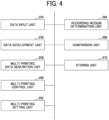
- FIG. 4 is a functional block diagram of the control unit 210 according to a first embodiment.
- the CPU 201 illustrated in FIG. 3 executes a program stored in the storage device such as the ROM 202 to implement the functions of a data input unit 254, a data development unit 256, a multi-printing data generation unit 258, a multi-printing control unit 260, a multi-printing setting unit 262, a recording-medium determination unit 264, a comparison unit 266, and a storing unit 270 illustrated in FIG. 4 .
- the external device and the sensor connected to the control unit 210 may implement a part of these functions.
- the data input unit 254 receives various data.
- the data input unit 254 receives print data from a client PC.
- the data input unit 254 can receive medium information.
- the medium information is information on the recording medium 2 and includes information on the material and color of the recording medium 2.
- Examples of the material of the recording medium 2 include paper and film.
- Examples of the information on the color of the recording medium 2 include white, black, and transparent.
- the data development unit 256 converts print data in a file format into a page description language (PDL) data, similarly to the printer driver.
- PDL page description language
- the position, size, color, and font of each character are designated and the position of an image in the print area of the recording medium 2 is designated.
- the multi-printing data generation unit 258 generates data for printing multiple times on the same side of the recording medium 2.
- the multi-printing data generation unit 258 generates the data for printing multiple times based on the medium information. A detailed description thereof is deferred.
- the multi-printing control unit 260 controls a printing operation and a medium conveying operation to print multiple times on the same side of the recording medium 2.
- the printing operation is a printing operation of the printing mechanism.
- the printing operation is a printing operation of the image forming device 30.
- the medium conveying operation is a conveying operation to convey the recording medium 2 to the image forming device 30.
- the medium conveying operation includes a medium conveying operation to return the recording medium 2 to perform the second and subsequent printing after the first printing.
- the medium conveying operation includes operations of the first conveyance mechanism 20 and the second conveyance mechanism 50. A detailed description thereof is deferred.
- the multi-printing setting unit 262 sets multiple times of printing on the same side based on, for example, the medium information and the print data.
- the multi-printing setting unit 262 may set the multiple times of printing on the same side based on, for example, information input by the user.
- the multi-printing setting unit 262 can set whether to print multiple times on the same side and the number of times of printing on the same side. A detailed description thereof is deferred.
- the recording-medium determination unit 264 determines the material and color of the recording medium 2.
- the recording-medium determination unit 264 may determine the material and color of the recording medium 2 based on the information input by the user through the control panel 111, for example.
- the recording-medium determination unit 264 may determine the material and color of the recording medium 2 based on an input tray of the sheet feeding device 10A or 10B selected by the user.
- the comparison unit 266 compares, with the print data, the color and density of an image as a print result, which is a result of printing based on the print data.
- the sensor 60 can detect the color and density of the image as the print result, which is the result of printing on the recording medium 2 as described above.
- the comparison unit 266 compares, with the print data, the color and density of the image as the print result detected by the sensor 60.
- the comparison unit 266 may compare, for example, the color and density of the image as the print result with a determination threshold based on the print data.
- the determination threshold is stored in advance in the storing unit 270, for example.
- the multi-printing setting unit 262 may change the number of times of printing based on the result of the comparison performed by the comparison unit 266.
- the multi-printing setting unit 262 can increase the number of times of printing when the color and density of the image as the print result is less than the determination threshold.
- the multi-printing setting unit 262 can increase the number of times of printing to bring the print result closer to the print data.
- the multi-printing setting unit 262 can reduce the number of times of printing when the color and density of the image as the print result is equal to or greater than the determination threshold.
- the multi-printing data generation unit 258 may change the data for printing based on the result of the comparison performed by the comparison unit 266.
- the multi-printing data generation unit 258 may change the data for the next printing to bring the print result closer to the initial print data when the color and density of the image as the print result is less than the determination threshold.
- the multi-printing data generation unit 258 changes the data for the second printing after the first printing.
- the multi-printing data generation unit 258 can change the data for the second and subsequent printing to change, for example, the color area, the color expression, and the color quality.
- the color area includes, for example, color and density.
- the storing unit 270 stores various kinds of information.
- the storing unit 270 stores, for example, a setting table for generating the data for printing multiple times.
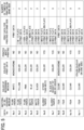
- FIG. 5 is an example of a setting table related to the data for printing multiple times on the same side.
- the storing unit 270 stores the setting table illustrated in FIG. 5 .
- the setting table includes data related to the material of the recording medium 2, data related to the color of the recording medium 2, data related to the color of the print data, data related to whether to perform white printing, data for printing multiple times on the same side, and data related to the number of times of printing on the same side.
- Examples of the data related to the material of the recording medium 2 include plain paper, matte paper, glossy paper, and film.
- Examples of the data related to the color of the recording medium 2 include white, yellow, pink, blue, black, a color other than white, black having a density of 65% or higher, and clear (transparent).
- Examples of the data related to the color of the print data include monochrome and color.
- the data related to the color of the print data may include information indicating duplex color printing on one side of the recording medium.
- Examples of the print data for printing on the same side include print data, print data 20%, white plate, M + C plate, Y20% + C plate, and Y + M20% plate.
- the print data referred herein is the initial print data before the data for printing multiple times is generated.
- the print data 20% indicates print data having a color density of 20%.
- the white plate indicates white printing.
- the M + C plate indicates printing in magenta (M) and cyan (C).
- the Y20% + C plate indicates printing in yellow (Y) having a density of 20% and cyan (C).
- Y + M20% plate indicates printing in yellow (Y) and magenta (M) having a density of 20%.
- the print data for printing on the same side may include data related to other colors, data related to density, and data related to the order of printing.
- the multi-printing control unit 260 can generate data for printing multiple times on the same side of the recording medium 2 with reference to the setting table illustrated in FIG. 5 , for example.
- the multi-printing data generation unit 258 can generate print data for printing multiple times by adjusting the color and/or density from the initial print data with reference to the setting table for adjustment ( FIG. 5 ) based on information such as the color and density of the original print data (initial print data), the color and material of the recording medium 2 on which an image is printed, and the printer (model) as the image forming apparatus 100.
- the print data for printing multiple times may be referred to as data for printing multiple times or simply as multi-printing data in the following description.
- the multi-printing data generation unit 258 can generate the multi-printing data for the first printing in magenta (M) and cyan (C) from the initial print data and then generate the multi-printing data for the second printing same as the initial print data on the same side.
- M magenta
- C cyan
- the image forming apparatus 100 can read, with the sensor 60, the color and/or density of the print result on the recording medium 2 being conveyed.
- the image forming apparatus 100 compares the color and/or density of the print result with the color and/or density of the print data instructed to be printed.
- the image forming apparatus 100 can end the printing and output the recording medium 2 when the difference in color and/or density is within a predetermined range.
- the operation of the image forming apparatus 100 may be controlled to eject the recording medium without printing based on the next multi-printing data.
- the multi-printing data generation unit 258 can additionally generate the multi-printing data to compensate for the insufficient color and/or density.
- the image forming apparatus 100 can perform additional printing on the same side based on the multi-printing data generated additionally. This can increase the number of times of printing.
- the multi-printing data generation unit 258 may generate the multi-printing data by subtraction of the color and/or density of the multi-printing data for the next printing and perform additional printing. This can prevent the color and/or density from exceeding the predetermined range in the next printing.
- the image forming apparatus 100 may cancel the multi-printing data for the subsequent printing, generate the multi-printing data for compensating for the excess of color and/or density, and print the generated multi-printing data.
- the multi-printing data includes print data generated by adjusting the color and/or density from the initial print data based on information such as the color and material of the recording medium 2 on which an image is printed, the printer (model), the color and/or density of the print result, and a setting table including the color and/or density and the number of times of printing.
- the color or density may be light or dark. Since the image forming apparatus 100 can generate the multi-printing data with the color and/or density adjusted from the initial print data, the image forming apparatus 100 can print with the color and/or density of the initial print data even when the color or material of the recording medium 2 changes or the printer (model) for printing changes, for example.
- the image forming apparatus 100 can perform the reverse conveying operation (switchback), which is an operation to reverse the recording medium 2 with the first conveyance mechanism 20 and the second conveyance mechanism 50.
- the image forming apparatus 100 can print on both the front side 2a and the back side 2b of the recording medium 2.
- the image forming apparatus 100 can print multiple times on the same side by performing the reverse conveying operation multiple times.
- the image forming apparatus 100 controls the operations of the first conveyance mechanism 20 and the second conveyance mechanism 50 to perform the reverse conveying operation twice after printing on the front side 2a.
- the multi-printing control unit 260 reverses the recording medium 2 twice (from the front side 2a to the back side 2b and back to the front side 2a), thus supplying the recording medium 2 to the transfer unit 32 to print on the front side 2a again.
- the image forming apparatus 100 reverses the recording medium 2 after the first printing on the front side 2a, performs the first printing on the back side 2b, reverses the recording medium 2 again, performs the second printing on the front side 2a, reverses the recording medium 2 again, and performs the second printing on the back side 2b. After the second printing on the back side 2b, the image forming apparatus 100 ejects the recording medium 2.
- the image forming apparatus 100 can perform an operation to print multiple times on the same side without using the reverse conveying operation.
- the recording medium 2 passes through the shortcut portion 52 after the first printing and is returned to the transfer unit 32 without passing through the switchback portion 51.
- the image forming apparatus 100 can print multiple times on the same side.
- the recording medium 2 can be supplied to the transfer unit 32 without being reversed.
- the image forming apparatus 100 returns the recording medium 2 to the transfer unit 32 through the shortcut portion 52 after the first printing on the front side 2a and performs the second printing on the front side 2a.
- the image forming apparatus 100 repeats this operation, thus continuously printing ten times in total on the front side 2a.
- the image forming apparatus 100 generates the data for printing multiple times on the same side of the recording medium 2.
- the multi-printing data generation unit 258 generates the data for printing multiple times on the same side of the recording medium 2.
- the multi-printing data generation unit 258 can set the number of times of printing and the printing order.
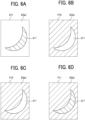
- FIGS. 6A to 6D are diagrams illustrating an example (Case 1) of the data for printing multiple times on the same side.
- FIG. 6A is a diagram illustrating print data D11.
- the print data D1 1 illustrated in FIG. 6A is image data representing a crescent d11 in yellow, for example.
- the difference in color is indicated by the difference in hatching.
- the example of the print data illustrated in FIGS. 6A to 6D corresponds to data No. 7 in FIG. 5 .
- FIG. 6B is a plan view of the front side 2a of the recording medium 2 after the first printing with print data P12 (white plate) based on the print data D11.
- FIG. 6C is a plan view of the front side 2a of the recording medium 2 after the second printing with the print data P12 (white plate) based on the print data D11.
- FIG. 6D is a plan view of the front side 2a of the recording medium 2 after the third printing with print data P11 (white plate) based on the print data D 11.
- the multi-printing data generation unit 258 generates the print data P11 and the print data P12 from the print data D11.
- the multi-printing data generation unit 258 generates the data for printing multiple times so that the printing is performed once based on the print data P11 after the printing is performed twice based on the print data P12.
- the print data P11 is image data representing the crescent d11 in yellow.
- the print data P12 is image data representing the crescent d11 in white.
- the image forming apparatus 100 can print the print data P11 after printing the print data P12 (white plate) twice on the recording medium 2 that is black glossy paper.
- FIGS. 7A to 7C are diagrams illustrating an example (Case 2) of the data for printing multiple times on the same side.
- the recording medium 2 in Case 2 is matte paper.
- the color of the recording medium 2 is black.
- FIG. 7A is a diagram illustrating print data D21.
- the print data D21 illustrated in FIG. 7A is image data representing a snowman d21 in white, for example.
- the snowman d21 wears a hat d22 in green, has eyes and mouth d23 in blue, and wears a muffler (scarf) d24 in red around the neck.
- the difference in color is indicated by the difference in hatching.
- the example of the print data illustrated in FIGS. 7A to 7C corresponds to data No. 5 in FIG. 5 .
- FIG. 7B is a plan view of the front side 2a of the recording medium 2 after the first printing with print data P21 based on the print data D21.
- FIG. 7C is a plan view of the front side 2a of the recording medium 2 after the second printing with the print data P21 based on the print data D21.
- the print data P21 for printing multiple times is the same data as the initial print data D21.
- the multi-printing data generation unit 258 generates the print data P21 for printing multiple times from the print data D21.
- the image forming apparatus 100 prints the print data P21 twice on the recording medium 2 that is black matte paper.
- FIGS. 8A to 8C are diagrams illustrating an example (Case 3) of the data for printing multiple times on the same side.
- the recording medium 2 in Case 3 is coated paper.
- the color of the recording medium 2 is black.
- FIG. 8A is a diagram illustrating the print data D21.
- the print data D21 illustrated in FIG. 8A is the same as that illustrated in FIG. 7A .
- the difference in color is indicated by the difference in hatching.
- FIG. 8B is a plan view of the front side 2a of the recording medium 2 after the first printing with print data P31 based on the print data D21.
- FIG. 8C is a plan view of the front side 2a of the recording medium 2 after the second printing with the print data P21 based on the print data D21.
- the print data P31 is print data of the white plate and includes the snowman d21 in white, the hat d22 in white, the eyes and mouth d23 in white, and the muffler d24 in white.
- the multi-printing data generation unit 258 generates the print data P21 and the print data P31 from the print data D21.
- the image forming apparatus 100 prints the print data P21 after printing the print data P31 on the recording medium 2 that is black coated paper.
- FIGS. 9A to 9C are diagrams illustrating an example (Case 4) of the data for printing multiple times on the same side.
- the recording medium 2 in Case 4 is thick paper.
- the color of the recording medium 2 is black.
- FIG. 9A is a diagram illustrating the print data D21.
- the print data D21 illustrated in FIG. 9A is the same as that illustrated in FIG. 7A .
- the difference in color is indicated by the difference in hatching.
- FIG. 9B is a plan view of the front side 2a of the recording medium 2 after the first printing with print data P41 based on the print data D21.
- FIG. 9C is a plan view of the front side 2a of the recording medium 2 after the second printing with the print data P21 based on the print data D21.
- the print data P41 includes the snowman d21 in white.
- the print data P41 does not include color data for the hat d22, the eyes and mouth d23, and the muffler d24.
- the multi-printing data generation unit 258 generates the print data P21 and the print data P41 from the print data D21.
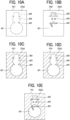
- FIGS. 10A to 10E are diagrams illustrating an example (Case 5) of the data for printing multiple times on the same side.
- the recording medium 2 in Case 5 is matte paper.
- the color of the recording medium 2 is black.
- FIG. 10A is a diagram illustrating print data D31.
- the print data D31 illustrated in FIG. 10A indicates the entire outline of the snowman d21, the hat d22, and the muffler d24, for example.
- the print data D31 does not include color data.
- the difference in color is indicated by the difference in hatching.
- Print data D32 illustrated in FIG. 10B indicates the hat d22 in green, the eyes and mouth d23 in blue, and the muffler d24 in red.
- the print data D32 may be data each in the same color.
- the print data may simply indicate the hat d22 in green, the eyes and mouth d23 in blue, or the muffler d24 in red.
- the print data D31 and the print data D32 are the initial print data received by the data input unit 254.
- FIG. 10C is a plan view of the front side 2a of the recording medium 2 after the first printing with the print data P31 based on the print data D31 and the print data D32.
- FIG. 10D is a plan view of the front side 2a of the recording medium 2 after the second printing with the print data P31 based on the print data D31 and the print data D32.
- FIG. 10E is a plan view of the front side 2a of the recording medium 2 after the third printing with print data P51 based on the print data D31 and the print data D32.
- the print data P31 is print data of the white plate and includes the snowman d21 in white, the hat d22 in white, the eyes and mouth d23 in white, and the muffler d24 in white.
- the print data P51 indicates the hat d22 in green, the eyes and mouth d23 in blue, and the muffler d24 in red, and may be the same as the print data D32.
- the multi-printing data generation unit 258 generates the print data P31 from the print data D31.
- the multi-printing data generation unit 258 generates the print data P51 from the print data D32.
- the image forming apparatus 100 prints the print data P51 after printing the print data P31 twice on the recording medium 2 that is black matte paper.
- the recording medium 2 in Case 6 is plain paper.
- the color of the recording medium 2 is yellow.
- the initial print data is color data.
- the image forming device 30 performs multicolor printing.
- the initial print data in Case 6 does not include white printing. Case 6 corresponds to data No. 2 in FIG. 5 .
- the multi-printing data generation unit 258 generates the print data of the M + C plate as first print data from the initial print data.
- the initial print data is used as second print data.
- the image forming apparatus 100 To perform color printing on the recording medium 2 that is yellow plain paper, the image forming apparatus 100 performs first printing based on the print data of the M + C plate, and then performs second printing based on the initial print data.
- the recording medium 2 in Case 7 is a film.
- the color of the recording medium 2 is clear (transparent).
- the initial print data is color data.
- the image forming device 30 performs multicolor printing.
- the initial print data in Case 7 includes white printing. Case 7 corresponds to data No. 10 in FIG. 5 .
- the multi-printing data generation unit 258 generates the print data of the white plate as the first print data from the initial print data.
- the print data of the white plate may include a specific portion in white or include the entire surface in white.
- the multi-printing data generation unit 258 generates the print data 20%, which is the print data having a color density of 20% of the color density of the initial print data, as the second print data from the initial print data.
- the initial print data is used as third print data.
- the image forming apparatus 100 To perform color printing on the recording medium 2 that is a transparent film, the image forming apparatus 100 performs the first printing based on the print data of the white plate, performs the second printing based on the print data 20%, and performs third printing based on the initial print data. After performing the second printing in a color at a first density (for example, 20%), the image forming apparatus 100 can perform the third printing in the color of the second printing at a second density (for example, 100%) higher than the first density.
- a first density for example, 20%
- the image forming apparatus 100 can perform the third printing in the color of the second printing at a second density (for example, 100%) higher than the first density.
- FIG. 11 is a flowchart illustrating a control process performed by the image forming apparatus 100 according to an embodiment of the present disclosure.
- the image forming apparatus 100 starts the process illustrated in FIG. 11 in response to an input of an instruction to start printing.
- the functional units illustrated in FIG. 4 allows the control unit 210 to perform the process illustrated in FIG. 11 .
- step S11 the image forming apparatus 100 starts printing.
- the control unit 210 receives a command signal from the printer driver 110 and starts printing.
- step S12 the control unit 210 acquires print data.
- the control unit 210 acquires initial print data from, for example, an external host PC.
- step S13 the control unit 210 acquires medium information.
- the control unit 210 can acquire the medium information included in the information acquired from the printer driver 110, for example.
- the control unit 210 may acquire the medium information based on an instruction input through the control panel 111.
- the control unit 210 acquires the information on the material and color of the recording medium 2 as the medium information.
- step S14 the multi-printing data generation unit 258 of the control unit 210 determines whether the print data for printing multiple times on the same side and the number of times of printing on the same side are required.
- the multi-printing data generation unit 258 determines whether the number of times of printing on the same side is required with reference to the setting table ( FIG. 5 ) stored in the storing unit 270.
- the determination as to whether the number of times of printing on the same side is required includes determination as to whether to print multiple times on the same side and calculation of the number of times of printing on the same side.
- the multi-printing data generation unit 258 determines the number of times of printing on the same side based on the medium information and the initial print data.
- the multi-printing data generation unit 258 determines that the number of times of printing on the same side is 1 (once).
- the multi-printing data generation unit 258 determines that the number of times of printing on the same side is 3 (three times).
- step S 15 the multi-printing data generation unit 258 determines whether white-plate data is required.
- the multi-printing data generation unit 258 determines whether the white-plate data is required based on the medium information and the print data with reference to the setting table illustrated in FIG. 5 .
- the multi-printing data generation unit 258 determines that the white-plate data is required (YES in step S15).
- the multi-printing data generation unit 258 determines that the white-plate data is not required (NO in step S15).
- the multi-printing data generation unit 258 determines that the white-plate data is required (YES in step S 15).
- the multi-printing data generation unit 258 determines that the white-plate data is not required (NO in step S15).
- step S 15 When the control unit 210 determines that the white-plate data is required (YES in step S 15), the process proceeds to step S16. When the control unit 210 determines that the white-plate data is not required (NO in step S 15), the process proceeds to step S 17.
- step S16 the multi-printing data generation unit 258 generates the white-plate data as print data for printing multiple times from the initial print data.
- the control unit 210 proceeds to step S17.
- step S17 the multi-printing data generation unit 258 determines whether designated-color data is required.
- the multi-printing data generation unit 258 determines whether the designated-color data is required based on the medium information and the print data with reference to the setting table illustrated in FIG. 5 .
- the "print data for printing on the same side” includes the "M + C plate,” “Y20% + C plate,” or "Y + M20% plate” in the setting table, the multi-printing data generation unit 258 determines that the designated-color data is required (YES in step S17).
- the multi-printing data generation unit 258 determines that the designated-color data is not required (NO in step S17).
- the multi-printing data generation unit 258 determines that the designated-color data ("M + C plate") is required (YES in step S17).
- the multi-printing data generation unit 258 determines that the designated-color data is not required (NO in step S17).
- step S17 When the control unit 210 determines that the designated-color data is required (YES in step S17), the process proceeds to step S18. When the control unit 210 determines that the designated-color data is not required (No in step S17), the process proceeds to step S19.
- step S18 the multi-printing data generation unit 258 generates designated-color data as print data for printing multiple times from the initial print data.
- the multi-printing data generation unit 258 generates the designated-color data of the corresponding color from the initial print data with reference to the setting table. For example, when the image forming apparatus 100 performs color printing on the recording medium 2 that is yellow plain paper, the multi-printing data generation unit 258 generates the designated-color data ("M + C plate").
- the control unit 210 proceeds to step S19.
- step S19 the multi-printing setting unit 262 determines whether printing multiple times on the same side is required.
- the multi-printing setting unit 262 determines whether printing multiple times on the same side is required based on the medium information and the print data with reference to the setting table illustrated in FIG. 5 .
- the multi-printing setting unit 262 determines that printing multiple times on the same side is required (YES in step S19).
- the multi-printing setting unit 262 determines that printing multiple times on the same side is not required (NO in step S19).
- the multi-printing setting unit 262 determines that printing multiple times on the same side is required (YES in step S19).
- the multi-printing setting unit 262 determines that printing multiple times on the same side is not required (NO in step S19).
- step S19 When the control unit 210 determines that printing multiple times on the same side is required (YES in step S19), the process proceeds to step S20. When the control unit 210 determines that printing multiple times on the same side is not required (NO in step S19), the process proceeds to step S21.
- step S20 the control unit 210 generates a table of the printing order of the print data for printing multiple times on the same side and the number of times of printing on the same side.
- the multi-printing data generation unit 258 may generate a table of the printing order of the print data for printing multiple times on the same side with reference to the setting table.
- the multi-printing setting unit 262 may generate a table of the number of times of printing on the same side with reference to the setting table.
- step S21 the image forming apparatus 100 prints on the recording medium 2.
- step S22 the control unit 210 determines whether printing multiple times on the same side is required.
- step S22 the control unit 210 performs the same operation as that in step S19.
- step S22 When the control unit 210 determines that printing multiple times on the same side is required (YES in step S22), the process proceeds to step S23. When the control unit 210 determines that printing multiple times on the same side is not required (NO in step S22), the process proceeds to step S24.
- step S23 the control unit 210 transmits an instruction to an identical printing mechanism of the second conveyance mechanism 50 to switch the conveyance of the recording medium 2.
- the identical printing mechanism of the second conveyance mechanism 50 switches the conveyance passage of the recording medium 2 so that the recording medium 2 passes through the shortcut portion 52 without passing through the switchback portion 51.
- the control unit 210 returns to step S21 and repeats the operations in steps S21 and S22.
- step S24 the control unit 210 determines whether the next page to be printed is present.
- the process returns to step S21.
- the control unit 210 determines that the next page to be printed is absent (NO in step S24)
- the process illustrated in FIG. 11 ends.
- the image forming apparatus 100 may include a preliminary sheet conveyance mechanism.
- the preliminary sheet conveyance mechanism allows a recording medium to pass through the first conveyance mechanism 20 and the second conveyance mechanism 50 before printing.
- the sheet conveyance means the conveyance of the recording medium 2.
- the image forming apparatus 100 can perform preliminary sheet conveyance before printing to stabilize the condition of the recording medium 2.
- the recording medium 2 is shrunk under heat.
- the recording medium 2 is conveyed without printing and shrunk in advance to reduce misalignment in the subsequent multiple times of printing.
- the image forming apparatus 100 may perform the preliminary sheet conveyance when the temperature of the fixing device 33 is lower than the normal temperature.
- the image forming apparatus 100 may include a standby mechanism 56.
- the image forming apparatus 100 can cool the recording medium 2 and dry the ink by standing by after printing. Thus, the image forming apparatus 100 can stabilize the condition of the recording medium 2.
- a sheet In a printer that heats and fixes toner, a sheet is heated by multiple times of printing, thus hampering the transfer of the toner.
- the image forming apparatus 100 dissipates the heat of the sheet to maintain the print quality even when printing multiple times thereafter.
- the operation screen 300 illustrated in FIG. 12 may be displayed on a display of a host PC that is an external apparatus connected to the control unit 210 or on the control panel 111.
- the operation screen 300 includes a display area 301 to display whether to print multiple times on the same side.
- the display area 301 displays ON/OFF to indicate whether to print multiple times on the same side. The user can select whether to print multiple times on the same side by selecting ON/OFF.
- the operation screen 300 includes a display area 302 to display the medium information.
- the display area 302 displays information on the material and color of the recording medium 2.
- the user can input the medium information by operating the operation screen 300 to select the material and color of the recording medium 2.
- the operation screen 300 includes a display area 303 to display a printer to be used.
- the display area 303 displays information on the model of the printer as the image forming apparatus 100. The user can select the model of the printer to be used by operating the operation screen 300.
- the operation screen 300 includes a display area 304 to display ON/OFF for the manual setting.
- the display area 304 displays ON/OFF to indicate whether to manually set the multiple times of printing on the same side. The user can select whether to manually set the multiple times of printing on the same side by operating the operation screen 300.
- the operation screen 300 includes a display area 305 to display items related to the setting of the multiple times of printing on the same side.
- the display area 305 displays "print target,” “print layer,” and “number of times of printing” as items related to the setting.
- the details displayed in the "print target” include “white plate” and "print data.”
- the details displayed in the "print layer” include “first layer (lowermost layer)” and “second layer (uppermost layer).”
- the details displayed in the "number of times of printing” include “automatic” and "2 (twice).”
- the user can change the setting of the multiple times of printing on the same side by operating the operation screen 300 to select the details of each item.
- the display area 305 may include keys for increasing or decreasing the display details.
- the operation screen 300 includes a display area 306 to display the setting as to whether to perform duplex printing on one side of the recording medium 2.
- the display area 306 displays ON/OFF to indicate whether to perform the duplex printing on one side. The user can select whether to perform the duplex printing on one side by operating the operation screen 300.
- the operation screen 300 includes a display area 307 to display the setting as to whether to read a print result and bring the print result closer to the color of the print data.
- a display area 307 displays ON/OFF to indicate whether to read a print result and bring the print result closer to the color of the print data. The user can select whether to read a print result and bring the print result closer to the color of the print data by operating the operation screen 300.
- the operation screen 300 includes a display area 308 to display the setting as to whether to convey a sheet (recording medium) before printing to stabilize the sheet condition.
- the "sheet condition" is the condition of the recording medium 2.
- the display area 308 displays ON/OFF to indicate whether to convey a sheet before printing to stabilize the sheet condition. The user can select whether to convey a sheet before printing to stabilize the sheet condition by operating the operation screen 300.
- the operation screen 300 includes a display area 309 to display the setting as to whether to stand by after printing to stabilize the sheet condition.
- a display area 309 displays ON/OFF to indicate whether to stand by after printing to stabilize the sheet condition. The user can select whether to stand by after printing to stabilize the sheet condition by operating the operation screen 300.
- the image forming apparatus 100 includes the image forming device 30, the first conveyance mechanism 20, the second conveyance mechanism 50, and the control unit 210.
- the image forming device 30 forms an image on the recording medium 2.
- the first conveyance mechanism 20 conveys the recording medium 2 to the secondary transfer roller 36.
- the second conveyance mechanism 50 conveys the recording medium 2 having passed through the secondary transfer roller 36 to the secondary transfer roller 36 again.
- the control unit 210 controls multiple times of printing operations of the secondary transfer roller 36.
- the image forming apparatus 100 can perform multiple times of printing on the same side of the recording medium 2 with the common image forming device 30.
- the multiple times of printing include the first printing and the second printing.
- the first printing is printing on the recording medium 2 based on first print data (the print data P31).
- the second printing is printing on the recording medium 2 subjected to the first printing based on second print data (the print data P21) different from the first print data.
- the image forming apparatus 100 having such a configuration can print multiple times on the front side 2a of the recording medium 2.
- the image forming apparatus 100 can form an image in the second printing on the front side 2a on which the image is formed in the first printing.
- the image forming apparatus 100 can enhance the color quality of images by printing multiple times on the same side (the front side 2a) of the recording medium 2. For example, when the density of the image is low resulting from the first printing, the color of the recording medium 2 may affect the color of the image, and the image in a desired color may not be obtained.
- the image forming apparatus 100 can prevent the color of the recording medium 2 from affecting the color of the image by printing twice or more on the same side of the recording medium 2.
- the multiple times of printing may be three or more times of printing.
- the second conveyance mechanism 50 can convey the recording medium 2 subjected to the first printing to the secondary transfer roller 36 without reversing the direction of conveyance of the recording medium 2.
- the recording medium 2 is conveyed through the shortcut portion 52 without passing through the switchback portion 51 to be supplied to the secondary transfer roller 36 again.
- the image forming apparatus 100 can shorten the time taken for conveyance of the recording medium 2. As a result, the printing efficiency of the image forming apparatus 100 can be enhanced.
- the image forming apparatus 100 further includes the sensor 60 serving as a medium detector that detects the color of the recording medium 2 before printing.
- the control unit 210 sets the number of times of printing on the recording medium 2 based on the color of the recording medium 2 detected by the sensor 60 and controls the operations of the first conveyance mechanism 20, the second conveyance mechanism 50, and the image forming device 30 to perform the set number of times of printing on the recording medium 2.
- the image forming apparatus 100 having such a configuration can change the number of times of printing on the recording medium 2 based on the color of the recording medium 2. Accordingly, the image forming apparatus 100 can enhance the color quality of images.
- the image forming apparatus 100 further includes the sensor 60 as a printed-side detector that detects the condition of the printed side (the front side 2a) of the recording medium 2 subjected to the first printing.
- the control unit 210 can change the number of times of printing on the same side of the recording medium 2 based on the condition of the printed side detected by the sensor 60.
- the multi-printing setting unit 262 can detect the color condition of the image on the printed side detected by the sensor 60 and increase or decrease the number of times of printing on the same side (the front side 2a) to bring the printed image closer to the initial print data. Accordingly, the image forming apparatus 100 can enhance the color quality of images.
- the image forming apparatus 100 includes the sensor 60 as a medium detector that detects the color of the recording medium 2 before printing.
- the control unit 210 sets the color and density of the print data to be printed on the recording medium 2 based on the color of the recording medium 2 detected by the sensor 60 and controls the operations of the first conveyance mechanism 20, the second conveyance mechanism 50, and the image forming device 30 to print on the recording medium 2 according to the set color and density of the print data.
- the image forming apparatus 100 having such a configuration can change the color to be printed on the recording medium 2 and the density of the color based on the color of the recording medium 2. Accordingly, the image forming apparatus 100 can enhance the color quality of images.
- the image forming apparatus 100 includes the sensor 60 as the printed-side detector that detects the condition of the printed side (the front side 2a) of the recording medium 2 subjected to the first printing.
- the control unit 210 can change the color and density of the print data to be printed on the same side of the recording medium 2 based on the condition of the printed side detected by the sensor 60.
- the multi-printing data generation unit 258 can detect the color condition of the image on the printed side detected by the sensor 60 and change the color and density of the print data to be printed on the same side (the front side 2a) to bring the printed image closer to the initial print data. Accordingly, the image forming apparatus 100 can enhance the color quality of images.
- the image forming apparatus 100 further includes the fixing device 33.
- the image forming device 30 forms a toner image on the recording medium 2.
- the fixing device 33 heats the recording medium 2 bearing the toner image formed by the image forming device 30 to fix the toner image on the recording medium 2.
- the control unit 210 causes the fixing device 33 to heat the recording medium 2 without toner so that a toner image is formed on the recording medium 2 heated by the fixing device 33.
- the recording medium 2 can pass the secondary transfer roller 36 and through the fixing device 33 before printing.
- the recording medium 2 can be heated and cooled before an image is formed on the recording medium 2. Since the recording medium 2 is shrunk before printing, the image forming apparatus 100 can print on the shrunk recording medium 2. As a result, the image forming apparatus 100 can reduce the misalignment of the printing positions due to the shrinkage of the recording medium 2.
- the standby mechanism 56 can stop the recording medium 2 after printing. Accordingly, after stabilizing the condition of the recording medium 2, the image forming apparatus 100 can perform the second and subsequent printing on the same side of the recording medium 2.
- the image forming device 30 can perform multicolor printing.
- the control unit 210 can control the operations of the first conveyance mechanism 20, the second conveyance mechanism 50, and the image forming device 30 to print in a single color on the recording medium 2 as the first printing, print in a color other than the single color at a first density as the second printing after the first printing, and print in the color of the second printing at a second density higher than the first density as third printing after the second printing.
- the image forming apparatus 100 having such a configuration can enhance the color density, color area, and color expression as the printing result.
- the image forming apparatus 100 can enhance the color quality.
- the single color may be, for example, white or another color.
- the image forming apparatus 100 can generate print data for enhancing a color area, color expression, and color quality from the print data.
- the image forming apparatus 100 can print multiple times on the same side of the recording medium 2. Therefore, the image forming apparatus 100 can print a color area and color expression that cannot be expressed by typical image forming apparatuses.
- the typical image forming apparatuses here refer to apparatuses that can print only once on the same side.
- the image forming apparatus 100 can print multiple times on the same side to enhance the color area, the color expression, and the color quality.
- An image forming system 1000 is an image forming system for printing multiple times on the same side of the recording medium 2 with the common image forming device 30.
- the image forming system includes the first conveyance mechanism 20, the second conveyance mechanism 50, and the control unit 210.
- the first conveyance mechanism 20 conveys the recording medium 2 to the image forming device 30.
- the second conveyance mechanism 50 conveys the recording medium 2 having passed through the image forming device 30 to the image forming device 30 again.
- the control unit 210 controls multiple times of printing operations of the image forming device 30.
- the control unit 210 controls the operations of the first conveyance mechanism 20, the second conveyance mechanism 50, and the image forming device 30 to cause the image forming device 30 to perform the first printing on the recording medium 2 based on first print data and perform the second printing on the recording medium 2 subjected to the first printing based on second print data different from the first print data.
- An image forming method is an image forming method for printing multiple times on the same side of the recording medium 2 with the common image forming device 30.
- the method includes first conveying, second conveying, and controlling.
- the first conveying includes conveying the recording medium 2 to the image forming device 30.
- the second conveying includes conveying the recording medium 2 having passed through the image forming device 30 to the image forming device 30 again.
- the controlling includes controlling multiple times of printing operations of the image forming device 30.
- the controlling includes controlling the operations of the first conveyance mechanism 20, the second conveyance mechanism 50, and the image forming device 30 to cause the image forming device 30 to perform the first printing on the recording medium 2 based on first print data and perform the second printing on the recording medium 2 subjected to the first printing based on second print data different from the first print data.
- the multicolor image forming apparatus 100 including the drum-shaped photoconductors for multiple colors is exemplified.
- the image forming apparatus may include a monochromatic drum-shaped photoconductor and perform monochromatic image formation.
- the image forming apparatus may be a liquid discharge apparatus.
- the liquid discharge apparatus includes a discharge head that discharges ink.
- an image forming apparatus incudes an image forming device, a first conveyance mechanism, a second conveyance mechanism, and a control unit.
- the image forming device forms an image on a recording medium.
- the first conveyance mechanism conveys the recording medium to the image forming device.
- the second conveyance mechanism conveys the recording medium having passed through the image forming device to the image forming device again.
- the control unit controls multiple times of printing operations of the image forming device.
- the image forming device can perform multiple times of printing on the same side of the recording medium.
- the multiple times of printing include first printing and second printing.
- the first printing is printing on the recording medium based on first print data.
- the second printing is printing on the recording medium subjected to the first printing based on second print data different from the first print data.
- the second conveyance mechanism conveys the recording medium subjected to the first printing to the image forming device without reversing a direction of conveyance of the recording medium.
- the image forming apparatus of the first or second aspect further includes a medium detector that detects the color of the recording medium before printing.
- the control unit sets the number of times of printing on the recording medium based on the color of the recording medium detected by the medium detector and controls the operations of the first conveyance mechanism, the second conveyance mechanism, and the image forming device to perform the set number of times of printing on the recording medium.
- the image forming apparatus of any one of the first to third aspects further includes a printed-side detector that detects the condition of a printed side of the recording medium subjected to the first printing.
- the control unit changes the number of times of printing on the recording medium based on the condition of the printed side detected by the printed-side detector.
- the image forming apparatus of any one of the first to fourth aspects further includes a medium detector that detects the color of the recording medium before printing.
- the control unit sets the color and density of print data to be printed on the recording medium based on the color of the recording medium detected by the medium detector and controls the operation of the image forming device to print on the recording medium according to the set color and density of the print data.
- the image forming apparatus of any one of the first to fifth aspects further includes a printed-side detector that detects the condition of a printed side of the recording medium subjected to the first printing.
- the control unit changes the color and density of print data to be printed on the recording medium based on the condition of the printed side detected by the printed-side detector.
- the image forming apparatus of any one of the first to sixth aspects further includes a fixing device.
- the image forming device forms a toner image on the recording medium in each of the first printing and the second printing.
- the fixing device heats the recording medium bearing the toner image formed by the image forming device to fix the toner image on the recording medium.
- the control unit causes the fixing device to heat a recording medium without toner and causes the image forming device to form the toner image on the recording medium heated by the fixing device.
- the second conveyance mechanism includes a standby mechanism that temporarily stops the recording medium subjected to the first printing and causes the recording medium to stand by.
- the control unit causes the image forming device to perform the second printing on the recording medium conveyed to the image forming device after controlling the operation of the standby mechanism to stop the recording medium subjected to the first printing.
- the image forming device can perform multicolor printing.
- the control unit controls the operations of the first conveyance mechanism, the second conveyance mechanism, and the image forming device to print in a single color on the recording medium as the first printing, print in a color other than the single color at a first density as the second printing after the first printing, and print in the color of the second printing at a second density higher than the first density as third printing after the second printing.
- an image forming system for printing multiple times on the same side of a recording medium with a common image forming device includes a first conveyance mechanism, a second conveyance mechanism, and a control unit.
- the first conveyance mechanism conveys the recording medium to the image forming device.
- the second conveyance mechanism conveys the recording medium having passed through the image forming device to the image forming device again.
- the control unit controls multiple times of printing operations of the image forming device.
- the control unit controls the operations of the first conveyance mechanism, the second conveyance mechanism, and the image forming device to cause the image forming device to perform first printing on the recording medium based on first print data and perform second printing on the recording medium subjected to the first printing based on second print data different from the first print data.
- an image forming method for printing multiple times on the same side of a recording medium with a common image forming device includes first conveying, second conveying, and controlling.
- the first conveying includes conveying the recording medium to the image forming device.
- the second conveying includes conveying the recording medium having passed through the image forming device to the image forming device again.
- the controlling includes controlling multiple times of printing operations of the image forming device.
- the controlling includes causing the image forming device to perform first printing on the recording medium based on first print data and perform second printing on the recording medium subjected to the first printing based on second print data different from the first print data.
- a carrier medium carries computer-readable code for controlling a computer system to carry out a method for printing multiple times on the same side of a recording medium with a common image forming device.
- the method includes first conveying, second conveying, and controlling.
- the first conveying includes conveying the recording medium to the image forming device.
- the second conveying includes conveying the recording medium having passed through the image forming device to the image forming device again.
- the controlling includes controlling multiple times of printing operations of the image forming device.
- the controlling includes causing the image forming device to perform first printing on the recording medium based on first print data and perform second printing on the recording medium subjected to the first printing based on second print data different from the first print data.
- the present invention can be implemented in any convenient form, for example using dedicated hardware, or a mixture of dedicated hardware and software.
- the present invention may be implemented as computer software implemented by one or more networked processing apparatuses.
- the processing apparatuses include any suitably programmed apparatuses such as a general purpose computer, a personal digital assistant, a Wireless Application Protocol (WAP) or third-generation (3G)-compliant mobile telephone, and so on. Since the present invention can be implemented as software, each and every aspect of the present invention thus encompasses computer software implementable on a programmable device.
- the computer software can be provided to the programmable device using any conventional carrier medium (carrier means).
- the carrier medium includes a transient carrier medium such as an electrical, optical, microwave, acoustic or radio frequency signal carrying the computer code.
- transient medium is a Transmission Control Protocol/Internet Protocol (TCP/IP) signal carrying computer code over an IP network, such as the Internet.
- the carrier medium may also include a storage medium for storing processor readable code such as a floppy disk, a hard disk, a compact disc read-only memory (CD-ROM), a magnetic tape device, or a solid state memory device.
Landscapes
- Engineering & Computer Science (AREA)
- Multimedia (AREA)
- Signal Processing (AREA)
- Physics & Mathematics (AREA)
- General Physics & Mathematics (AREA)
- Microelectronics & Electronic Packaging (AREA)
- Accessory Devices And Overall Control Thereof (AREA)
- Control Or Security For Electrophotography (AREA)
- Color Electrophotography (AREA)
Abstract
An image forming apparatus (100) includes an image forming device (30), a first conveyance mechanism (20), a second conveyance mechanism (50), and a control unit (210). The image forming device (30) forms an image on a recording medium. The first conveyance mechanism (20) conveys the recording medium to the image forming device (30). The second conveyance mechanism (50) conveys the recording medium having passed through the image forming device (30) to the image forming device (30) again. The control unit (210) controls multiple times of printing operations of the image forming device (30). The image forming device (30) performs multiple times of printing on a same side of the recording medium. The multiple times of printing include first printing and second printing. The first printing is printing on the recording medium based on first print data. The second printing is printing on the recording medium subjected to the first printing based on second print data different from the first print data.
Description
- The present disclosure relates to an image forming apparatus, an image forming system, an image forming method, and a carrier medium.
- Some known image forming apparatuses include an image forming device to form an image on a sheet, an image forming passage to convey a sheet to the image forming device, and a reverse passage to reverse the sheet and cause the reversed sheet to enter the image forming passage (for example, see
Japanese Patent No. 6981066 Japanese Patent No. 6981066 -
Japanese Patent No. 6981066 Japanese Patent No. 6981066 - According to an embodiment of the present invention, an image forming apparatus includes an image forming device, a first conveyance mechanism, a second conveyance mechanism, and a control unit. The image forming device forms an image on a recording medium. The first conveyance mechanism conveys the recording medium to the image forming device. The second conveyance mechanism conveys the recording medium having passed through the image forming device to the image forming device again. The control unit controls multiple times of printing operations of the image forming device. The image forming device performs multiple times of printing on a same side of the recording medium. The multiple times of printing include first printing and second printing. The first printing is printing on the recording medium based on first print data. The second printing is printing on the recording medium subjected to the first printing based on second print data different from the first print data.
- According to an embodiment of the present invention, an image forming system for printing multiple times on a same side of a recording medium with an image forming device includes a first conveyance mechanism, a second conveyance mechanism, and a control unit. The first conveyance mechanism conveys the recording medium to the image forming device. The second conveyance mechanism conveys the recording medium having passed through the image forming device to the image forming device again. The control unit controls multiple times of printing operations of the image forming device. The control unit controls operations of the first conveyance mechanism, the second conveyance mechanism, and the image forming device to cause the image forming device to perform first printing on the recording medium based on first print data and perform second printing on the recording medium subjected to the first printing based on second print data different from the first print data.
- According to an embodiment of the present invention, an image forming method for printing multiple times on a same side of a recording medium with an image forming device includes first conveying the recording medium to the image forming device, second conveying the recording medium having passed through the image forming device to the image forming device again, and controlling multiple times of printing operations of the image forming device. The controlling includes causing the image forming device to perform first printing on the recording medium based on first print data and perform second printing on the recording medium subjected to the first printing based on second print data different from the first print data.
- According to an embodiment of the present invention, a carrier medium carries computer-readable code for controlling a computer system to carry out a method for printing multiple times on a same side of a recording medium with an image forming device. The method includes first conveying the recording medium to the image forming device, second conveying the recording medium having passed through the image forming device to the image forming device again, and controlling multiple times of printing operations of the image forming device. The controlling includes causing the image forming device to perform first printing on the recording medium based on first print data and perform second printing on the recording medium subjected to the first printing based on second print data different from the first print data.
- Accordingly, an image forming apparatus is provided that enhances the color quality of an image.
- A more complete appreciation of embodiments of the present disclosure and many of the attendant advantages and features thereof can be readily obtained and understood from the following detailed description with reference to the accompanying drawings, wherein:
-
FIG. 1 is a schematic diagram illustrating a configuration of an image forming apparatus according to an embodiment of the present disclosure; -
FIGS. 2A and 2B are plan views of example front and back sides of a recording medium; -
FIG. 3 is a block diagram illustrating a hardware configuration of an image forming apparatus according to an embodiment of the present disclosure; -
FIG. 4 is a functional block diagram of an image forming apparatus according to an embodiment of the present disclosure; -
FIG. 5 is an example of a setting table related to data for printing multiple times on the same side of a recording medium; -
FIGS. 6A to 6D are diagrams illustrating an example (Case 1) of data for printing multiple times on the same side of a recording medium; -
FIGS. 7A to 7C are diagrams illustrating an example (Case 2) of data for printing multiple times on the same side of a recording medium; -
FIGS. 8A to 8C are diagrams illustrating an example (Case 3) of data for printing multiple times on the same side of a recording medium; -
FIGS. 9A to 9C are diagrams illustrating an example (Case 4) of data for printing multiple times on the same side of a recording medium; -
FIGS. 10A to 10E are diagrams an example (Case 5) of data for printing multiple times on the same side of a recording medium; -
FIG. 11 is a flowchart illustrating a control process performed by an image forming apparatus according to an embodiment of the present disclosure; and -
FIG. 12 is a diagram of an example of an operation screen for setting the multiple times of printing on the same side of a recording medium. - The accompanying drawings are intended to depict embodiments of the present disclosure and should not be interpreted to limit the scope thereof. The accompanying drawings are not to be considered as drawn to scale unless explicitly noted. Also, identical or similar reference numerals designate identical or similar components throughout the several views.
- In describing embodiments illustrated in the drawings, specific terminology is employed for the sake of clarity. However, the disclosure of this specification is not intended to be limited to the specific terminology so selected and it is to be understood that each specific element includes all technical equivalents that have a similar function, operate in a similar manner, and achieve a similar result.
- Referring now to the drawings, embodiments of the present disclosure are described below.
- As used herein, the singular forms "a," "an," and "the" are intended to include the plural forms as well, unless the context clearly indicates otherwise. The term "connected/coupled" includes both direct connections and connections in which there are one or more intermediate connecting elements.
- In the specification and drawings, substantially the same components are denoted by the same reference numerals, and redundant description thereof may be omitted.
- In the following description, image formation, print, printing, and recording are all synonymous.
- A description is given below of an
image forming apparatus 100 according to an embodiment of the present disclosure. -
FIG. 1 is a schematic diagram illustrating a configuration of theimage forming apparatus 100 according to an embodiment of the present disclosure. - In the example illustrated in
FIG. 1 , theimage forming apparatus 100 is an electrophotographic tandem-type color image forming apparatus. Theimage forming apparatus 100 includessheet feeding devices first conveyance mechanism 20, animage forming device 30, afixing device 33, asheet ejection device 40, and asecond conveyance mechanism 50. - The
image forming device 30 includes anintermediate transfer belt 35, multiple drum-shapedphotoconductors intermediate transfer belt 35, and atransfer unit 32. In theimage forming apparatus 100, theimage forming device 30 forms a full-color image on a recording medium supplied from thesheet feeding device first conveyance mechanism 20, thefirst conveyance mechanism 20 conveys the recording medium bearing the full-color image and ejects the recording medium to thesheet ejection device 40. -
FIGS. 2A and 2B are plan views of example front and back sides of arecording medium 2. - Specifically,
FIG. 2A is a plan view of afront side 2a of therecording medium 2.FIG. 2B is a plan view of aback side 2b of therecording medium 2. - The
recording medium 2 is a sheet-shapedrecording medium 2 having a predetermined thickness. Theback side 2b is an opposite side of thefront side 2a in the thickness direction of therecording medium 2. Thefront side 2a is an example of a first side of the recording medium. Theback side 2b may be a second side of the recording medium. - The
recording medium 2 may be, for example, a sheet or a transparent film. The sheet may be, for example, a white sheet or a black sheet. The color of the sheet may be another color such as yellow, pink, or blue. Therecording medium 2 may be a medium other than the sheet and the transparent film. - As illustrated in
FIG. 1 , thesheet feeding devices recording media 2. Thesheet feeding devices recording media 2 from each other. The different types ofrecording media 2 include different materials or different colors. Thesheet feeding device 10A holds therecording media 2 such as white sheets. Thesheet feeding device 10B holds therecording media 2 such as black sheets. Theimage forming apparatus 100 may include sheet feeding devices that hold three or more types ofrecording media 2 or may include a sheet feeding device that holds one type ofrecording media 2. - The
first conveyance mechanism 20 is a conveyance mechanism that supplies therecording media 2 held in thesheet feeding devices transfer unit 32. Thefirst conveyance mechanism 20 includes a conveyance mechanism that conveys therecording medium 2 having passed thetransfer unit 32 of theimage forming device 30. Therecording medium 2 having passed thetransfer unit 32 is sent to thesheet ejection device 40 or thesecond conveyance mechanism 50 in a subsequent stage. Thefirst conveyance mechanism 20 includes conveyance roller pairs 22 that convey therecording medium 2. Thefirst conveyance mechanism 20 includes a guide that guides the conveyance of therecording medium 2. - The
image forming device 30 includes thetransfer unit 32. Thetransfer unit 32 includes the drum-shapedphotoconductors intermediate transfer belt 35, and asecondary transfer roller 36. Theintermediate transfer belt 35 is an endless belt on which an intermediate transfer image is formed. Theintermediate transfer belt 35 rotates. The drum-shapedphotoconductors intermediate transfer belt 35 rotates. - The drum-shaped
photoconductor 34K transfers a black toner onto theintermediate transfer belt 35 to form a black toner image on the surface ofintermediate transfer belt 35. The drum-shapedphotoconductor 34C transfers a cyan toner onto theintermediate transfer belt 35 to form a cyan toner image on the surface of theintermediate transfer belt 35. The drum-shapedphotoconductor 34M transfers a magenta toner onto theintermediate transfer belt 35 to form a magenta toner image on the surface of theintermediate transfer belt 35. The drum-shapedphotoconductor 34Y transfers a yellow toner onto theintermediate transfer belt 35 to form a yellow toner image on the surface of theintermediate transfer belt 35. - The drum-shaped
photoconductor 34S transfers a special toner onto theintermediate transfer belt 35 to form a special toner image on the surface of theintermediate transfer belt 35. Examples of the special toner include white, gold, silver, fluorescent, fluorescent coloring, clear, and intermediate color toners. - The
secondary transfer roller 36 transfers the toner image formed on theintermediate transfer belt 35 to thefront side 2a or theback side 2b of therecording medium 2. - The fixing
device 33 includes a fixing roller and a heater. The fixingdevice 33 fixes the toner image that has been transferred to therecording medium 2 to thefront side 2a or theback side 2b of therecording medium 2. Thus, an image is formed on thefront side 2a or theback side 2b of therecording medium 2. The fixingdevice 33 fixes the toner image to therecording medium 2 by heating and pressing therecording medium 2 to which the toner image has been transferred. The heater may be, for example, a halogen heater. The heater is built in the fixing roller. - The
sheet ejection device 40 includes an output tray to which therecording medium 2 subjected to printing is ejected. Therecording medium 2 on which printing is completed is ejected to thesheet ejection device 40. - The
second conveyance mechanism 50 is a conveyance mechanism that supplies therecording medium 2 having passed through theimage forming device 30 to theimage forming device 30 again. Thesecond conveyance mechanism 50 includes a conveyance passage to return therecording medium 2 that is not ejected to theimage forming device 30 again. Thesecond conveyance mechanism 50 includes aswitchback portion 51, ashortcut portion 52, and areturn portion 53. Theswitchback portion 51 reverses the direction of conveyance of therecording medium 2 to convey therecording medium 2 backward. The reversedrecording medium 2 passes through thereturn portion 53 and is supplied to thetransfer unit 32 through thefirst conveyance mechanism 20. For example, to form an image on theback side 2b after forming another image on thefront side 2a, therecording medium 2 is introduced into theswitchback portion 51 where the direction of conveyance of therecording medium 2 is reversed and is supplied to thetransfer unit 32 through thereturn portion 53. - The
shortcut portion 52 supplies therecording medium 2 to thereturn portion 53 without routing therecording medium 2 through theswitchback portion 51. Therecording medium 2 having passed through theshortcut portion 52 passes through thereturn portion 53 without reversing the direction of conveyance and is supplied to the fixingdevice 33 through thefirst conveyance mechanism 20. For example, to form an image on thefront side 2a and form another image on thefront side 2a again, therecording medium 2 is supplied to thetransfer unit 32 through theshortcut portion 52. Thesecond conveyance mechanism 50 includes multiple conveyance roller pairs 54 to convey therecording medium 2. - Referring to
FIG. 3 , a description is given below of a hardware configuration of theimage forming apparatus 100. -
FIG. 3 is a block diagram illustrating the hardware configuration of theimage forming apparatus 100 according to an embodiment of the present disclosure. - The
image forming apparatus 100 includes a controller 200 that includes acontrol unit 210. - A
printer driver 110 is connected to thecontrol unit 210. Theprinter driver 110 generates print data. Theprinter driver 110 may generate print data in an information processing terminal such as a personal computer (PC), an image reading apparatus such as an image scanner, or a host apparatus such as an imaging apparatus such as a digital camera. Theprinter driver 110 generates dot pattern data for theimage forming apparatus 100 to output an image. - A
control unit 210 includes a central processing unit (CPU) 201, a read-only memory (ROM) 202, a random-access memory (RAM) 203, and a non-volatile random-access memory (NVRAM) 204. - The
CPU 201 is a calculation unit and controls the operation of the entireimage forming apparatus 100. TheCPU 201 performs control related to an operation to convey therecording medium 2 and a printing operation of theimage forming device 30. TheROM 202 is a read-only non-volatile storage medium. TheROM 202 stores programs such as firmware. TheRAM 203 is a volatile storage medium capable of reading and writing information at high speed. TheRAM 203 is used as a work area for theCPU 201 to process information. - The
NVRAM 204 is a non-volatile storage medium capable of reading and writing information. TheNVRAM 204 stores, for example, an operating system (OS), various control programs, and application programs. - The
CPU 201 reads a program from a storage device and loads the program into theRAM 203. TheCPU 201 executes calculations according to the program loaded into theRAM 203. Thus, a software control unit is configured. The storage device includes theROM 202 and theNVRAM 204. The storage device may include a storage medium such as an optical disk. - The software control unit cooperates with hardware to implement functions, illustrated as functional blocks, of the
image forming apparatus 100. TheCPU 201 and theRAM 203 function as the various control units as illustrated inFIG. 3 . The various control units will be described later. - The
image forming apparatus 100 includes acontrol panel 111. Thecontrol panel 111 is connected to thecontrol unit 210. Thecontrol panel 111 is an input unit operable by a user to input instructions. Thecontrol panel 111 may be, for example, a liquid crystal panel. The user can change printing settings by operating thecontrol panel 111. The user can also change various settings by operating thecontrol panel 111. - The user can input information on the
recording medium 2 by operating thecontrol panel 111. The user can input, for example, whether therecording medium 2 is a white sheet by operating thecontrol panel 111. Information input through thecontrol panel 111 is transmitted to thecontrol unit 210. Thecontrol panel 111 may be a display and an input unit of a terminal (PC) connected to thecontrol unit 210. - The
image forming apparatus 100 includes asensor 60. Thesensor 60 is a sensor that detects the color and density of an image formed on therecording medium 2. Thesensor 60 may be disposed, for example, downstream from the fixingdevice 33 in direction of conveyance of therecording medium 2 in the conveyance passage through which therecording medium 2 is conveyed. Thesensor 60 may be disposed in the conveyance passage defined by thefirst conveyance mechanism 20 or in the conveyance passage defined by thesecond conveyance mechanism 50. Thesensor 60 may be a camera that images the printed side of therecording medium 2. The printed side is a surface on which an image is formed. - Referring to
FIG. 4 , a description is given below of a functional configuration of thecontrol unit 210. -
FIG. 4 is a functional block diagram of thecontrol unit 210 according to a first embodiment. - The
CPU 201 illustrated inFIG. 3 executes a program stored in the storage device such as theROM 202 to implement the functions of adata input unit 254, adata development unit 256, a multi-printingdata generation unit 258, amulti-printing control unit 260, amulti-printing setting unit 262, a recording-medium determination unit 264, acomparison unit 266, and astoring unit 270 illustrated inFIG. 4 . The external device and the sensor connected to thecontrol unit 210 may implement a part of these functions. - The
data input unit 254 receives various data. For example, thedata input unit 254 receives print data from a client PC. Thedata input unit 254 can receive medium information. - The medium information is information on the
recording medium 2 and includes information on the material and color of therecording medium 2. Examples of the material of therecording medium 2 include paper and film. Examples of the information on the color of therecording medium 2 include white, black, and transparent. - For example, the
data development unit 256 converts print data in a file format into a page description language (PDL) data, similarly to the printer driver. In the PDL, for example, the position, size, color, and font of each character are designated and the position of an image in the print area of therecording medium 2 is designated. - The multi-printing
data generation unit 258 generates data for printing multiple times on the same side of therecording medium 2. The multi-printingdata generation unit 258 generates the data for printing multiple times based on the medium information. A detailed description thereof is deferred. - The
multi-printing control unit 260 controls a printing operation and a medium conveying operation to print multiple times on the same side of therecording medium 2. The printing operation is a printing operation of the printing mechanism. In other words, the printing operation is a printing operation of theimage forming device 30. The medium conveying operation is a conveying operation to convey therecording medium 2 to theimage forming device 30. The medium conveying operation includes a medium conveying operation to return therecording medium 2 to perform the second and subsequent printing after the first printing. The medium conveying operation includes operations of thefirst conveyance mechanism 20 and thesecond conveyance mechanism 50. A detailed description thereof is deferred. - The
multi-printing setting unit 262 sets multiple times of printing on the same side based on, for example, the medium information and the print data. Themulti-printing setting unit 262 may set the multiple times of printing on the same side based on, for example, information input by the user. Themulti-printing setting unit 262 can set whether to print multiple times on the same side and the number of times of printing on the same side. A detailed description thereof is deferred. - The recording-
medium determination unit 264 determines the material and color of therecording medium 2. The recording-medium determination unit 264 may determine the material and color of therecording medium 2 based on the information input by the user through thecontrol panel 111, for example. The recording-medium determination unit 264 may determine the material and color of therecording medium 2 based on an input tray of thesheet feeding device - The
comparison unit 266 compares, with the print data, the color and density of an image as a print result, which is a result of printing based on the print data. Thesensor 60 can detect the color and density of the image as the print result, which is the result of printing on therecording medium 2 as described above. Thecomparison unit 266 compares, with the print data, the color and density of the image as the print result detected by thesensor 60. Thecomparison unit 266 may compare, for example, the color and density of the image as the print result with a determination threshold based on the print data. The determination threshold is stored in advance in thestoring unit 270, for example. - The
multi-printing setting unit 262 may change the number of times of printing based on the result of the comparison performed by thecomparison unit 266. Themulti-printing setting unit 262 can increase the number of times of printing when the color and density of the image as the print result is less than the determination threshold. Themulti-printing setting unit 262 can increase the number of times of printing to bring the print result closer to the print data. Themulti-printing setting unit 262 can reduce the number of times of printing when the color and density of the image as the print result is equal to or greater than the determination threshold. - The multi-printing
data generation unit 258 may change the data for printing based on the result of the comparison performed by thecomparison unit 266. The multi-printingdata generation unit 258 may change the data for the next printing to bring the print result closer to the initial print data when the color and density of the image as the print result is less than the determination threshold. When theimage forming apparatus 100 prints multiple times, the multi-printingdata generation unit 258 changes the data for the second printing after the first printing. The multi-printingdata generation unit 258 can change the data for the second and subsequent printing to change, for example, the color area, the color expression, and the color quality. The color area includes, for example, color and density. - The storing
unit 270 stores various kinds of information. The storingunit 270 stores, for example, a setting table for generating the data for printing multiple times. -
FIG. 5 is an example of a setting table related to the data for printing multiple times on the same side. - The storing
unit 270 stores the setting table illustrated inFIG. 5 . The setting table includes data related to the material of therecording medium 2, data related to the color of therecording medium 2, data related to the color of the print data, data related to whether to perform white printing, data for printing multiple times on the same side, and data related to the number of times of printing on the same side. - Examples of the data related to the material of the
recording medium 2 include plain paper, matte paper, glossy paper, and film. Examples of the data related to the color of therecording medium 2 include white, yellow, pink, blue, black, a color other than white, black having a density of 65% or higher, and clear (transparent). Examples of the data related to the color of the print data include monochrome and color. The data related to the color of the print data may include information indicating duplex color printing on one side of the recording medium. - Examples of the print data for printing on the same side include print data,
print data 20%, white plate, M + C plate, Y20% + C plate, and Y + M20% plate. The print data referred herein is the initial print data before the data for printing multiple times is generated. Theprint data 20% indicates print data having a color density of 20%. The white plate indicates white printing. The M + C plate indicates printing in magenta (M) and cyan (C). The Y20% + C plate indicates printing in yellow (Y) having a density of 20% and cyan (C). Y + M20% plate indicates printing in yellow (Y) and magenta (M) having a density of 20%. The print data for printing on the same side may include data related to other colors, data related to density, and data related to the order of printing. - The
multi-printing control unit 260 can generate data for printing multiple times on the same side of therecording medium 2 with reference to the setting table illustrated inFIG. 5 , for example. - A description is given below of data for printing multiple times.
- The multi-printing
data generation unit 258 can generate print data for printing multiple times by adjusting the color and/or density from the initial print data with reference to the setting table for adjustment (FIG. 5 ) based on information such as the color and density of the original print data (initial print data), the color and material of therecording medium 2 on which an image is printed, and the printer (model) as theimage forming apparatus 100. The print data for printing multiple times may be referred to as data for printing multiple times or simply as multi-printing data in the following description. - For example, when the
image forming apparatus 100 prints on therecording medium 2 that is yellow plain paper as a non-white-printing printer, the multi-printingdata generation unit 258 can generate the multi-printing data for the first printing in magenta (M) and cyan (C) from the initial print data and then generate the multi-printing data for the second printing same as the initial print data on the same side. - When the
image forming apparatus 100 prints on therecording medium 2 that is pink plain paper as a non-white-printing printer, the multi-printingdata generation unit 258 may generate the multi-printing data for the first printing in yellow(Y) having a density of 20% and cyan (C) from the initial print data and then generate the multi-printing data for the second printing same as the initial print data on the same side. - The
image forming apparatus 100 can read, with thesensor 60, the color and/or density of the print result on therecording medium 2 being conveyed. Theimage forming apparatus 100 compares the color and/or density of the print result with the color and/or density of the print data instructed to be printed. Thus, theimage forming apparatus 100 can end the printing and output therecording medium 2 when the difference in color and/or density is within a predetermined range. - When the difference in color and/or density is within the predetermined range and the multi-printing data for the next printing is present in the
image forming apparatus 100, the operation of theimage forming apparatus 100 may be controlled to eject the recording medium without printing based on the next multi-printing data. - When the difference in color and/or density is lower than the predetermined range and the multi-printing data for the next printing is absent in the
image forming apparatus 100, the multi-printingdata generation unit 258 can additionally generate the multi-printing data to compensate for the insufficient color and/or density. Theimage forming apparatus 100 can perform additional printing on the same side based on the multi-printing data generated additionally. This can increase the number of times of printing. - When the difference in color and/or density is lower than the predetermined range but exceeds the predetermined range when the
image forming apparatus 100 prints the multi-printing data for the next printing, the multi-printingdata generation unit 258 may generate the multi-printing data by subtraction of the color and/or density of the multi-printing data for the next printing and perform additional printing. This can prevent the color and/or density from exceeding the predetermined range in the next printing. - When the difference in color and/or density is greater than the predetermined range and the multi-printing data for compensating for the excess of color and/or density can be generated, the
image forming apparatus 100 may cancel the multi-printing data for the subsequent printing, generate the multi-printing data for compensating for the excess of color and/or density, and print the generated multi-printing data. - The multi-printing data includes print data generated by adjusting the color and/or density from the initial print data based on information such as the color and material of the
recording medium 2 on which an image is printed, the printer (model), the color and/or density of the print result, and a setting table including the color and/or density and the number of times of printing. - When normal print data is printed multiple times, the color or density may be light or dark. Since the
image forming apparatus 100 can generate the multi-printing data with the color and/or density adjusted from the initial print data, theimage forming apparatus 100 can print with the color and/or density of the initial print data even when the color or material of therecording medium 2 changes or the printer (model) for printing changes, for example. - A description is given below of an operation to print multiple times on the same side using a reverse conveying operation.
- The
image forming apparatus 100 can perform the reverse conveying operation (switchback), which is an operation to reverse therecording medium 2 with thefirst conveyance mechanism 20 and thesecond conveyance mechanism 50. Theimage forming apparatus 100 can print on both thefront side 2a and theback side 2b of therecording medium 2. Theimage forming apparatus 100 can print multiple times on the same side by performing the reverse conveying operation multiple times. - For example, to print twice on the
front side 2a of therecording medium 2, theimage forming apparatus 100 controls the operations of thefirst conveyance mechanism 20 and thesecond conveyance mechanism 50 to perform the reverse conveying operation twice after printing on thefront side 2a. After printing on thefront side 2a, themulti-printing control unit 260 reverses therecording medium 2 twice (from thefront side 2a to theback side 2b and back to thefront side 2a), thus supplying therecording medium 2 to thetransfer unit 32 to print on thefront side 2a again. - To print twice on each of the
front side 2a and theback side 2b, theimage forming apparatus 100 reverses therecording medium 2 after the first printing on thefront side 2a, performs the first printing on theback side 2b, reverses therecording medium 2 again, performs the second printing on thefront side 2a, reverses therecording medium 2 again, and performs the second printing on theback side 2b. After the second printing on theback side 2b, theimage forming apparatus 100 ejects therecording medium 2. - A description is given below of an operation to print multiple times on the same side without using the reverse conveying operation.
- The
image forming apparatus 100 can perform an operation to print multiple times on the same side without using the reverse conveying operation. In theimage forming apparatus 100, therecording medium 2 passes through theshortcut portion 52 after the first printing and is returned to thetransfer unit 32 without passing through theswitchback portion 51. Thus, theimage forming apparatus 100 can print multiple times on the same side. In theimage forming apparatus 100, therecording medium 2 can be supplied to thetransfer unit 32 without being reversed. For example, to print ten times simply on thefront side 2a, theimage forming apparatus 100 returns therecording medium 2 to thetransfer unit 32 through theshortcut portion 52 after the first printing on thefront side 2a and performs the second printing on thefront side 2a. Theimage forming apparatus 100 repeats this operation, thus continuously printing ten times in total on thefront side 2a. - A description is given below of the generation of the multi-printing data.
- The
image forming apparatus 100 generates the data for printing multiple times on the same side of therecording medium 2. Specifically, the multi-printingdata generation unit 258 generates the data for printing multiple times on the same side of therecording medium 2. In addition, the multi-printingdata generation unit 258 can set the number of times of printing and the printing order. - A description is given below of a first case (Case 1) of generating the multi-printing data.
-
FIGS. 6A to 6D are diagrams illustrating an example (Case 1) of the data for printing multiple times on the same side. - The
recording medium 2 inCase 1 is glossy paper. The color of therecording medium 2 is black.FIG. 6A is a diagram illustrating print data D11. Theprint data D1 1 illustrated inFIG. 6A is image data representing a crescent d11 in yellow, for example. InFIGS. 6A to 6D , the difference in color is indicated by the difference in hatching. The example of the print data illustrated inFIGS. 6A to 6D corresponds to data No. 7 inFIG. 5 . -
FIG. 6B is a plan view of thefront side 2a of therecording medium 2 after the first printing with print data P12 (white plate) based on the print data D11.FIG. 6C is a plan view of thefront side 2a of therecording medium 2 after the second printing with the print data P12 (white plate) based on the print data D11.FIG. 6D is a plan view of thefront side 2a of therecording medium 2 after the third printing with print data P11 (white plate) based on the print data D 11. - The multi-printing
data generation unit 258 generates the print data P11 and the print data P12 from the print data D11. The multi-printingdata generation unit 258 generates the data for printing multiple times so that the printing is performed once based on the print data P11 after the printing is performed twice based on the print data P12. The print data P11 is image data representing the crescent d11 in yellow. The print data P12 is image data representing the crescent d11 in white. - The
image forming apparatus 100 can print the print data P11 after printing the print data P12 (white plate) twice on therecording medium 2 that is black glossy paper. - A description is given below of a second case (Case 2) of generating the multi-printing data.
-
FIGS. 7A to 7C are diagrams illustrating an example (Case 2) of the data for printing multiple times on the same side. - The
recording medium 2 inCase 2 is matte paper. The color of therecording medium 2 is black. -
FIG. 7A is a diagram illustrating print data D21. The print data D21 illustrated inFIG. 7A is image data representing a snowman d21 in white, for example. In print data D21, the snowman d21 wears a hat d22 in green, has eyes and mouth d23 in blue, and wears a muffler (scarf) d24 in red around the neck. InFIGS. 7A to 7C , the difference in color is indicated by the difference in hatching. The example of the print data illustrated inFIGS. 7A to 7C corresponds to data No. 5 inFIG. 5 . -
FIG. 7B is a plan view of thefront side 2a of therecording medium 2 after the first printing with print data P21 based on the print data D21.FIG. 7C is a plan view of thefront side 2a of therecording medium 2 after the second printing with the print data P21 based on the print data D21. The print data P21 for printing multiple times is the same data as the initial print data D21. - The multi-printing
data generation unit 258 generates the print data P21 for printing multiple times from the print data D21. - The
image forming apparatus 100 prints the print data P21 twice on therecording medium 2 that is black matte paper. - A description is given below of a third case (Case 3) of generating the multi-printing data.
-
FIGS. 8A to 8C are diagrams illustrating an example (Case 3) of the data for printing multiple times on the same side. - The
recording medium 2 inCase 3 is coated paper. The color of therecording medium 2 is black. -
FIG. 8A is a diagram illustrating the print data D21. The print data D21 illustrated inFIG. 8A is the same as that illustrated inFIG. 7A . InFIGS. 8A to 8C , the difference in color is indicated by the difference in hatching. -
FIG. 8B is a plan view of thefront side 2a of therecording medium 2 after the first printing with print data P31 based on the print data D21.FIG. 8C is a plan view of thefront side 2a of therecording medium 2 after the second printing with the print data P21 based on the print data D21. The print data P31 is print data of the white plate and includes the snowman d21 in white, the hat d22 in white, the eyes and mouth d23 in white, and the muffler d24 in white. - The multi-printing
data generation unit 258 generates the print data P21 and the print data P31 from the print data D21. - The
image forming apparatus 100 prints the print data P21 after printing the print data P31 on therecording medium 2 that is black coated paper. - A description is given below of a fourth case (Case 4) of generating the multi-printing data.
-
FIGS. 9A to 9C are diagrams illustrating an example (Case 4) of the data for printing multiple times on the same side. - The
recording medium 2 in Case 4 is thick paper. The color of therecording medium 2 is black. -
FIG. 9A is a diagram illustrating the print data D21. The print data D21 illustrated inFIG. 9A is the same as that illustrated inFIG. 7A . InFIGS. 9A to 9C , the difference in color is indicated by the difference in hatching. -
FIG. 9B is a plan view of thefront side 2a of therecording medium 2 after the first printing with print data P41 based on the print data D21.FIG. 9C is a plan view of thefront side 2a of therecording medium 2 after the second printing with the print data P21 based on the print data D21. The print data P41 includes the snowman d21 in white. The print data P41 does not include color data for the hat d22, the eyes and mouth d23, and the muffler d24. - The multi-printing
data generation unit 258 generates the print data P21 and the print data P41 from the print data D21. - The
image forming apparatus 100 prints the print data P21 after printing the print data P41 on therecording medium 2 that is black, thick paper. - A description is given below of a fifth case (Case 5) of generating the multi-printing data.
-
FIGS. 10A to 10E are diagrams illustrating an example (Case 5) of the data for printing multiple times on the same side. - The
recording medium 2 in Case 5 is matte paper. The color of therecording medium 2 is black. -
FIG. 10A is a diagram illustrating print data D31. The print data D31 illustrated inFIG. 10A indicates the entire outline of the snowman d21, the hat d22, and the muffler d24, for example. The print data D31 does not include color data. InFIGS. 10A to 10E , the difference in color is indicated by the difference in hatching. - Print data D32 illustrated in
FIG. 10B indicates the hat d22 in green, the eyes and mouth d23 in blue, and the muffler d24 in red. The print data D32 may be data each in the same color. The print data may simply indicate the hat d22 in green, the eyes and mouth d23 in blue, or the muffler d24 in red. - The print data D31 and the print data D32 are the initial print data received by the
data input unit 254. -
FIG. 10C is a plan view of thefront side 2a of therecording medium 2 after the first printing with the print data P31 based on the print data D31 and the print data D32. -
FIG. 10D is a plan view of thefront side 2a of therecording medium 2 after the second printing with the print data P31 based on the print data D31 and the print data D32. -
FIG. 10E is a plan view of thefront side 2a of therecording medium 2 after the third printing with print data P51 based on the print data D31 and the print data D32. The print data P31 is print data of the white plate and includes the snowman d21 in white, the hat d22 in white, the eyes and mouth d23 in white, and the muffler d24 in white. The print data P51 indicates the hat d22 in green, the eyes and mouth d23 in blue, and the muffler d24 in red, and may be the same as the print data D32. - The multi-printing
data generation unit 258 generates the print data P31 from the print data D31. The multi-printingdata generation unit 258 generates the print data P51 from the print data D32. - The
image forming apparatus 100 prints the print data P51 after printing the print data P31 twice on therecording medium 2 that is black matte paper. - A description is given below of a sixth case (Case 6) of generating the multi-printing data.
- The
recording medium 2 in Case 6 is plain paper. The color of therecording medium 2 is yellow. The initial print data is color data. Theimage forming device 30 performs multicolor printing. The initial print data in Case 6 does not include white printing. Case 6 corresponds to data No. 2 inFIG. 5 . - The multi-printing
data generation unit 258 generates the print data of the M + C plate as first print data from the initial print data. The initial print data is used as second print data. - To perform color printing on the
recording medium 2 that is yellow plain paper, theimage forming apparatus 100 performs first printing based on the print data of the M + C plate, and then performs second printing based on the initial print data. - A description is given below of a seventh case (Case 7) of generating the multi-printing data.
- The
recording medium 2 in Case 7 is a film. The color of therecording medium 2 is clear (transparent). The initial print data is color data. Theimage forming device 30 performs multicolor printing. The initial print data in Case 7 includes white printing. Case 7 corresponds to data No. 10 inFIG. 5 . - The multi-printing
data generation unit 258 generates the print data of the white plate as the first print data from the initial print data. The print data of the white plate may include a specific portion in white or include the entire surface in white. The multi-printingdata generation unit 258 generates theprint data 20%, which is the print data having a color density of 20% of the color density of the initial print data, as the second print data from the initial print data. The initial print data is used as third print data. - To perform color printing on the
recording medium 2 that is a transparent film, theimage forming apparatus 100 performs the first printing based on the print data of the white plate, performs the second printing based on theprint data 20%, and performs third printing based on the initial print data. After performing the second printing in a color at a first density (for example, 20%), theimage forming apparatus 100 can perform the third printing in the color of the second printing at a second density (for example, 100%) higher than the first density. - Referring to
FIG. 11 , a description is given below of a control process performed by theimage forming apparatus 100. -
FIG. 11 is a flowchart illustrating a control process performed by theimage forming apparatus 100 according to an embodiment of the present disclosure. - For example, the
image forming apparatus 100 starts the process illustrated inFIG. 11 in response to an input of an instruction to start printing. The functional units illustrated inFIG. 4 allows thecontrol unit 210 to perform the process illustrated inFIG. 11 . - In step S11, the
image forming apparatus 100 starts printing. Thecontrol unit 210 receives a command signal from theprinter driver 110 and starts printing. In step S12, thecontrol unit 210 acquires print data. Thecontrol unit 210 acquires initial print data from, for example, an external host PC. In step S13, thecontrol unit 210 acquires medium information. Thecontrol unit 210 can acquire the medium information included in the information acquired from theprinter driver 110, for example. Thecontrol unit 210 may acquire the medium information based on an instruction input through thecontrol panel 111. Thecontrol unit 210 acquires the information on the material and color of therecording medium 2 as the medium information. - In step S14, the multi-printing
data generation unit 258 of thecontrol unit 210 determines whether the print data for printing multiple times on the same side and the number of times of printing on the same side are required. The multi-printingdata generation unit 258 determines whether the number of times of printing on the same side is required with reference to the setting table (FIG. 5 ) stored in thestoring unit 270. The determination as to whether the number of times of printing on the same side is required includes determination as to whether to print multiple times on the same side and calculation of the number of times of printing on the same side. The multi-printingdata generation unit 258 determines the number of times of printing on the same side based on the medium information and the initial print data. - For example, when the
image forming apparatus 100 performs monochrome printing on therecording medium 2 that is white plain paper, the multi-printingdata generation unit 258 determines that the number of times of printing on the same side is 1 (once). When theimage forming apparatus 100 performs color printing on therecording medium 2 that is black glossy paper, the multi-printingdata generation unit 258 determines that the number of times of printing on the same side is 3 (three times). - In step S 15, the multi-printing
data generation unit 258 determines whether white-plate data is required. The multi-printingdata generation unit 258 determines whether the white-plate data is required based on the medium information and the print data with reference to the setting table illustrated inFIG. 5 . When the "print data for printing on the same side" includes the "white plate" in the setting table, the multi-printingdata generation unit 258 determines that the white-plate data is required (YES in step S15). When the "print data for printing on the same side" does not include the "white plate" in the setting table, the multi-printingdata generation unit 258 determines that the white-plate data is not required (NO in step S15). - For example, when the
image forming apparatus 100 performs color printing on therecording medium 2 that is black glossy paper, the multi-printingdata generation unit 258 determines that the white-plate data is required (YES in step S 15). When theimage forming apparatus 100 performs color printing on therecording medium 2 that is black matte paper, the multi-printingdata generation unit 258 determines that the white-plate data is not required (NO in step S15). - When the
control unit 210 determines that the white-plate data is required (YES in step S 15), the process proceeds to step S16. When thecontrol unit 210 determines that the white-plate data is not required (NO in step S 15), the process proceeds to step S 17. - In step S16, the multi-printing
data generation unit 258 generates the white-plate data as print data for printing multiple times from the initial print data. After the operation in step S 16, thecontrol unit 210 proceeds to step S17. - In step S17, the multi-printing
data generation unit 258 determines whether designated-color data is required. The multi-printingdata generation unit 258 determines whether the designated-color data is required based on the medium information and the print data with reference to the setting table illustrated inFIG. 5 . When the "print data for printing on the same side" includes the "M + C plate," "Y20% + C plate," or "Y + M20% plate" in the setting table, the multi-printingdata generation unit 258 determines that the designated-color data is required (YES in step S17). When the "print data for printing on the same side" does not include the "M + C plate," "Y20% + C plate," or "Y + M20% plate" in the setting table, the multi-printingdata generation unit 258 determines that the designated-color data is not required (NO in step S17). - For example, when the
image forming apparatus 100 performs color printing on therecording medium 2 that is yellow plain paper, the multi-printingdata generation unit 258 determines that the designated-color data ("M + C plate") is required (YES in step S17). When theimage forming apparatus 100 performs color printing on therecording medium 2 that is black glossy paper, the multi-printingdata generation unit 258 determines that the designated-color data is not required (NO in step S17). - When the
control unit 210 determines that the designated-color data is required (YES in step S17), the process proceeds to step S18. When thecontrol unit 210 determines that the designated-color data is not required (No in step S17), the process proceeds to step S19. - In step S18, the multi-printing
data generation unit 258 generates designated-color data as print data for printing multiple times from the initial print data. The multi-printingdata generation unit 258 generates the designated-color data of the corresponding color from the initial print data with reference to the setting table. For example, when theimage forming apparatus 100 performs color printing on therecording medium 2 that is yellow plain paper, the multi-printingdata generation unit 258 generates the designated-color data ("M + C plate"). After the operation in step S18, thecontrol unit 210 proceeds to step S19. - In step S19, the
multi-printing setting unit 262 determines whether printing multiple times on the same side is required. Themulti-printing setting unit 262 determines whether printing multiple times on the same side is required based on the medium information and the print data with reference to the setting table illustrated inFIG. 5 . When the "number of times of printing on the same side" indicates 2 (twice) or more in the setting table, themulti-printing setting unit 262 determines that printing multiple times on the same side is required (YES in step S19). When the "number of times of printing on the same side" indicates 1 (once) in the setting table, themulti-printing setting unit 262 determines that printing multiple times on the same side is not required (NO in step S19). - For example, when the
image forming apparatus 100 performs color printing on therecording medium 2 that is black glossy paper, themulti-printing setting unit 262 determines that printing multiple times on the same side is required (YES in step S19). When theimage forming apparatus 100 performs monochrome printing on therecording medium 2 that is white plain paper, themulti-printing setting unit 262 determines that printing multiple times on the same side is not required (NO in step S19). - When the
control unit 210 determines that printing multiple times on the same side is required (YES in step S19), the process proceeds to step S20. When thecontrol unit 210 determines that printing multiple times on the same side is not required (NO in step S19), the process proceeds to step S21. - In step S20, the
control unit 210 generates a table of the printing order of the print data for printing multiple times on the same side and the number of times of printing on the same side. The multi-printingdata generation unit 258 may generate a table of the printing order of the print data for printing multiple times on the same side with reference to the setting table. Themulti-printing setting unit 262 may generate a table of the number of times of printing on the same side with reference to the setting table. - For example, when the
image forming apparatus 100 performs color printing on therecording medium 2 that is black glossy paper, thecontrol unit 210 generates the table of the printing order so that the white plate is printed as the first printing, the white plate is printed as the second printing, and the print data is printed as the third printing. In this case, thecontrol unit 210 generates the table of the number of times of printing indicating the number of times of printing as 3 (three times). After the operation in step S20, thecontrol unit 210 proceeds to step S21. - In step S21, the
image forming apparatus 100 prints on therecording medium 2. In step S22, thecontrol unit 210 determines whether printing multiple times on the same side is required. In step S22, thecontrol unit 210 performs the same operation as that in step S19. - When the
control unit 210 determines that printing multiple times on the same side is required (YES in step S22), the process proceeds to step S23. When thecontrol unit 210 determines that printing multiple times on the same side is not required (NO in step S22), the process proceeds to step S24. - In step S23, the
control unit 210 transmits an instruction to an identical printing mechanism of thesecond conveyance mechanism 50 to switch the conveyance of therecording medium 2. The identical printing mechanism of thesecond conveyance mechanism 50 switches the conveyance passage of therecording medium 2 so that therecording medium 2 passes through theshortcut portion 52 without passing through theswitchback portion 51. After the operation in step S23, thecontrol unit 210 returns to step S21 and repeats the operations in steps S21 and S22. - In step S24, the
control unit 210 determines whether the next page to be printed is present. When thecontrol unit 210 determines that the next page to be printed is present (YES in step S24), the process returns to step S21. When thecontrol unit 210 determines that the next page to be printed is absent (NO in step S24), the process illustrated inFIG. 11 ends. - The
image forming apparatus 100 may include a preliminary sheet conveyance mechanism. The preliminary sheet conveyance mechanism allows a recording medium to pass through thefirst conveyance mechanism 20 and thesecond conveyance mechanism 50 before printing. The sheet conveyance means the conveyance of therecording medium 2. Theimage forming apparatus 100 can perform preliminary sheet conveyance before printing to stabilize the condition of therecording medium 2. In a printer that heats and fixes toner, therecording medium 2 is shrunk under heat. In theimage forming apparatus 100, therecording medium 2 is conveyed without printing and shrunk in advance to reduce misalignment in the subsequent multiple times of printing. Theimage forming apparatus 100 may perform the preliminary sheet conveyance when the temperature of the fixingdevice 33 is lower than the normal temperature. - The
image forming apparatus 100 may include astandby mechanism 56. Theimage forming apparatus 100 can cool therecording medium 2 and dry the ink by standing by after printing. Thus, theimage forming apparatus 100 can stabilize the condition of therecording medium 2. - In a printer that heats and fixes toner, a sheet is heated by multiple times of printing, thus hampering the transfer of the toner. The
image forming apparatus 100 dissipates the heat of the sheet to maintain the print quality even when printing multiple times thereafter. - Referring to
FIG. 12 , a description is given of an example of anoperation screen 300 for setting the multiple times of printing on the same side. - For example, the
operation screen 300 illustrated inFIG. 12 may be displayed on a display of a host PC that is an external apparatus connected to thecontrol unit 210 or on thecontrol panel 111. - The
operation screen 300 includes adisplay area 301 to display whether to print multiple times on the same side. Thedisplay area 301 displays ON/OFF to indicate whether to print multiple times on the same side. The user can select whether to print multiple times on the same side by selecting ON/OFF. - The
operation screen 300 includes adisplay area 302 to display the medium information. Thedisplay area 302 displays information on the material and color of therecording medium 2. The user can input the medium information by operating theoperation screen 300 to select the material and color of therecording medium 2. - The
operation screen 300 includes adisplay area 303 to display a printer to be used. Thedisplay area 303 displays information on the model of the printer as theimage forming apparatus 100. The user can select the model of the printer to be used by operating theoperation screen 300. - The
operation screen 300 includes adisplay area 304 to display ON/OFF for the manual setting. Thedisplay area 304 displays ON/OFF to indicate whether to manually set the multiple times of printing on the same side. The user can select whether to manually set the multiple times of printing on the same side by operating theoperation screen 300. - The
operation screen 300 includes adisplay area 305 to display items related to the setting of the multiple times of printing on the same side. Thedisplay area 305 displays "print target," "print layer," and "number of times of printing" as items related to the setting. The details displayed in the "print target" include "white plate" and "print data." The details displayed in the "print layer" include "first layer (lowermost layer)" and "second layer (uppermost layer)." The details displayed in the "number of times of printing" include "automatic" and "2 (twice)." The user can change the setting of the multiple times of printing on the same side by operating theoperation screen 300 to select the details of each item. Thedisplay area 305 may include keys for increasing or decreasing the display details. - The
operation screen 300 includes adisplay area 306 to display the setting as to whether to perform duplex printing on one side of therecording medium 2. Thedisplay area 306 displays ON/OFF to indicate whether to perform the duplex printing on one side. The user can select whether to perform the duplex printing on one side by operating theoperation screen 300. - The
operation screen 300 includes adisplay area 307 to display the setting as to whether to read a print result and bring the print result closer to the color of the print data. Adisplay area 307 displays ON/OFF to indicate whether to read a print result and bring the print result closer to the color of the print data. The user can select whether to read a print result and bring the print result closer to the color of the print data by operating theoperation screen 300. - The
operation screen 300 includes adisplay area 308 to display the setting as to whether to convey a sheet (recording medium) before printing to stabilize the sheet condition. The "sheet condition" is the condition of therecording medium 2. Thedisplay area 308 displays ON/OFF to indicate whether to convey a sheet before printing to stabilize the sheet condition. The user can select whether to convey a sheet before printing to stabilize the sheet condition by operating theoperation screen 300. - The
operation screen 300 includes adisplay area 309 to display the setting as to whether to stand by after printing to stabilize the sheet condition. Adisplay area 309 displays ON/OFF to indicate whether to stand by after printing to stabilize the sheet condition. The user can select whether to stand by after printing to stabilize the sheet condition by operating theoperation screen 300. - A description is given below of several operational advantages of the
image forming apparatus 100 according to the first embodiment. - The
image forming apparatus 100 according to the first embodiment includes theimage forming device 30, thefirst conveyance mechanism 20, thesecond conveyance mechanism 50, and thecontrol unit 210. Theimage forming device 30 forms an image on therecording medium 2. Thefirst conveyance mechanism 20 conveys therecording medium 2 to thesecondary transfer roller 36. Thesecond conveyance mechanism 50 conveys therecording medium 2 having passed through thesecondary transfer roller 36 to thesecondary transfer roller 36 again. Thecontrol unit 210 controls multiple times of printing operations of thesecondary transfer roller 36. Theimage forming apparatus 100 can perform multiple times of printing on the same side of therecording medium 2 with the commonimage forming device 30. The multiple times of printing include the first printing and the second printing. The first printing is printing on therecording medium 2 based on first print data (the print data P31). The second printing is printing on therecording medium 2 subjected to the first printing based on second print data (the print data P21) different from the first print data. - The
image forming apparatus 100 having such a configuration can print multiple times on thefront side 2a of therecording medium 2. Theimage forming apparatus 100 can form an image in the second printing on thefront side 2a on which the image is formed in the first printing. Theimage forming apparatus 100 can enhance the color quality of images by printing multiple times on the same side (thefront side 2a) of therecording medium 2. For example, when the density of the image is low resulting from the first printing, the color of therecording medium 2 may affect the color of the image, and the image in a desired color may not be obtained. Theimage forming apparatus 100 can prevent the color of therecording medium 2 from affecting the color of the image by printing twice or more on the same side of therecording medium 2. The multiple times of printing may be three or more times of printing. - In the
image forming apparatus 100, thesecond conveyance mechanism 50 can convey therecording medium 2 subjected to the first printing to thesecondary transfer roller 36 without reversing the direction of conveyance of therecording medium 2. - In the
image forming apparatus 100 having such a configuration, therecording medium 2 is conveyed through theshortcut portion 52 without passing through theswitchback portion 51 to be supplied to thesecondary transfer roller 36 again. By supplying therecording medium 2 to thesecondary transfer roller 36 without reversing the direction of conveyance of therecording medium 2, theimage forming apparatus 100 can shorten the time taken for conveyance of therecording medium 2. As a result, the printing efficiency of theimage forming apparatus 100 can be enhanced. - The
image forming apparatus 100 further includes thesensor 60 serving as a medium detector that detects the color of therecording medium 2 before printing. Thecontrol unit 210 sets the number of times of printing on therecording medium 2 based on the color of therecording medium 2 detected by thesensor 60 and controls the operations of thefirst conveyance mechanism 20, thesecond conveyance mechanism 50, and theimage forming device 30 to perform the set number of times of printing on therecording medium 2. - The
image forming apparatus 100 having such a configuration can change the number of times of printing on therecording medium 2 based on the color of therecording medium 2. Accordingly, theimage forming apparatus 100 can enhance the color quality of images. - The
image forming apparatus 100 further includes thesensor 60 as a printed-side detector that detects the condition of the printed side (thefront side 2a) of therecording medium 2 subjected to the first printing. Thecontrol unit 210 can change the number of times of printing on the same side of therecording medium 2 based on the condition of the printed side detected by thesensor 60. - The
multi-printing setting unit 262 can detect the color condition of the image on the printed side detected by thesensor 60 and increase or decrease the number of times of printing on the same side (thefront side 2a) to bring the printed image closer to the initial print data. Accordingly, theimage forming apparatus 100 can enhance the color quality of images. - The
image forming apparatus 100 includes thesensor 60 as a medium detector that detects the color of therecording medium 2 before printing. Thecontrol unit 210 sets the color and density of the print data to be printed on therecording medium 2 based on the color of therecording medium 2 detected by thesensor 60 and controls the operations of thefirst conveyance mechanism 20, thesecond conveyance mechanism 50, and theimage forming device 30 to print on therecording medium 2 according to the set color and density of the print data. - The
image forming apparatus 100 having such a configuration can change the color to be printed on therecording medium 2 and the density of the color based on the color of therecording medium 2. Accordingly, theimage forming apparatus 100 can enhance the color quality of images. - The
image forming apparatus 100 includes thesensor 60 as the printed-side detector that detects the condition of the printed side (thefront side 2a) of therecording medium 2 subjected to the first printing. Thecontrol unit 210 can change the color and density of the print data to be printed on the same side of therecording medium 2 based on the condition of the printed side detected by thesensor 60. - The multi-printing
data generation unit 258 can detect the color condition of the image on the printed side detected by thesensor 60 and change the color and density of the print data to be printed on the same side (thefront side 2a) to bring the printed image closer to the initial print data. Accordingly, theimage forming apparatus 100 can enhance the color quality of images. - The
image forming apparatus 100 further includes the fixingdevice 33. In each of the first printing and second printing, theimage forming device 30 forms a toner image on therecording medium 2. The fixingdevice 33 heats therecording medium 2 bearing the toner image formed by theimage forming device 30 to fix the toner image on therecording medium 2. Thecontrol unit 210 causes the fixingdevice 33 to heat therecording medium 2 without toner so that a toner image is formed on therecording medium 2 heated by the fixingdevice 33. - In the
image forming apparatus 100, therecording medium 2 can pass thesecondary transfer roller 36 and through the fixingdevice 33 before printing. Thus, in theimage forming apparatus 100, therecording medium 2 can be heated and cooled before an image is formed on therecording medium 2. Since therecording medium 2 is shrunk before printing, theimage forming apparatus 100 can print on the shrunk recordingmedium 2. As a result, theimage forming apparatus 100 can reduce the misalignment of the printing positions due to the shrinkage of therecording medium 2. - In the
image forming apparatus 100, thesecond conveyance mechanism 50 includes thestandby mechanism 56 that temporarily stops therecording medium 2 subjected to the first printing and causes therecording medium 2 to stand by. After controlling the operation of thestandby mechanism 56 to stop therecording medium 2 subjected to the first printing, thecontrol unit 210 controls the operations of thefirst conveyance mechanism 20, thesecond conveyance mechanism 50, and thesecondary transfer roller 36 to convey therecording medium 2 to thesecondary transfer roller 36 and perform the second printing. - In the
image forming apparatus 100 having such a configuration, thestandby mechanism 56 can stop therecording medium 2 after printing. Accordingly, after stabilizing the condition of therecording medium 2, theimage forming apparatus 100 can perform the second and subsequent printing on the same side of therecording medium 2. - In the
image forming apparatus 100, theimage forming device 30 can perform multicolor printing. Thecontrol unit 210 can control the operations of thefirst conveyance mechanism 20, thesecond conveyance mechanism 50, and theimage forming device 30 to print in a single color on therecording medium 2 as the first printing, print in a color other than the single color at a first density as the second printing after the first printing, and print in the color of the second printing at a second density higher than the first density as third printing after the second printing. - The
image forming apparatus 100 having such a configuration can enhance the color density, color area, and color expression as the printing result. Theimage forming apparatus 100 can enhance the color quality. - The
image forming apparatus 100 can generate print data for enhancing a color area, color expression, and color quality from the print data. Theimage forming apparatus 100 can print multiple times on the same side of therecording medium 2. Therefore, theimage forming apparatus 100 can print a color area and color expression that cannot be expressed by typical image forming apparatuses. The typical image forming apparatuses here refer to apparatuses that can print only once on the same side. Theimage forming apparatus 100 can print multiple times on the same side to enhance the color area, the color expression, and the color quality. - A description is given below of an image forming system.
- An
image forming system 1000 according to one or more embodiments is an image forming system for printing multiple times on the same side of therecording medium 2 with the commonimage forming device 30. The image forming system includes thefirst conveyance mechanism 20, thesecond conveyance mechanism 50, and thecontrol unit 210. Thefirst conveyance mechanism 20 conveys therecording medium 2 to theimage forming device 30. Thesecond conveyance mechanism 50 conveys therecording medium 2 having passed through theimage forming device 30 to theimage forming device 30 again. Thecontrol unit 210 controls multiple times of printing operations of theimage forming device 30. Thecontrol unit 210 controls the operations of thefirst conveyance mechanism 20, thesecond conveyance mechanism 50, and theimage forming device 30 to cause theimage forming device 30 to perform the first printing on therecording medium 2 based on first print data and perform the second printing on therecording medium 2 subjected to the first printing based on second print data different from the first print data. - A description is given below of an image forming method.
- An image forming method according to one or more embodiments is an image forming method for printing multiple times on the same side of the
recording medium 2 with the commonimage forming device 30. The method includes first conveying, second conveying, and controlling. The first conveying includes conveying therecording medium 2 to theimage forming device 30. The second conveying includes conveying therecording medium 2 having passed through theimage forming device 30 to theimage forming device 30 again. The controlling includes controlling multiple times of printing operations of theimage forming device 30. The controlling includes controlling the operations of thefirst conveyance mechanism 20, thesecond conveyance mechanism 50, and theimage forming device 30 to cause theimage forming device 30 to perform the first printing on therecording medium 2 based on first print data and perform the second printing on therecording medium 2 subjected to the first printing based on second print data different from the first print data. - In the above-described embodiment, the multicolor
image forming apparatus 100 including the drum-shaped photoconductors for multiple colors is exemplified. However, the image forming apparatus may include a monochromatic drum-shaped photoconductor and perform monochromatic image formation. - The image forming apparatus may be a liquid discharge apparatus. The liquid discharge apparatus includes a discharge head that discharges ink.
- A description is given below of several aspects of the present disclosure.
- According to a first aspect, an image forming apparatus incudes an image forming device, a first conveyance mechanism, a second conveyance mechanism, and a control unit. The image forming device forms an image on a recording medium. The first conveyance mechanism conveys the recording medium to the image forming device. The second conveyance mechanism conveys the recording medium having passed through the image forming device to the image forming device again. The control unit controls multiple times of printing operations of the image forming device. The image forming device can perform multiple times of printing on the same side of the recording medium. The multiple times of printing include first printing and second printing. The first printing is printing on the recording medium based on first print data. The second printing is printing on the recording medium subjected to the first printing based on second print data different from the first print data.
- According to a second aspect, in the image forming apparatus of the first aspect, the second conveyance mechanism conveys the recording medium subjected to the first printing to the image forming device without reversing a direction of conveyance of the recording medium.
- According to a third aspect, the image forming apparatus of the first or second aspect further includes a medium detector that detects the color of the recording medium before printing. The control unit sets the number of times of printing on the recording medium based on the color of the recording medium detected by the medium detector and controls the operations of the first conveyance mechanism, the second conveyance mechanism, and the image forming device to perform the set number of times of printing on the recording medium.
- According to a fourth aspect, the image forming apparatus of any one of the first to third aspects further includes a printed-side detector that detects the condition of a printed side of the recording medium subjected to the first printing. The control unit changes the number of times of printing on the recording medium based on the condition of the printed side detected by the printed-side detector.
- According to a fifth aspect, the image forming apparatus of any one of the first to fourth aspects further includes a medium detector that detects the color of the recording medium before printing. The control unit sets the color and density of print data to be printed on the recording medium based on the color of the recording medium detected by the medium detector and controls the operation of the image forming device to print on the recording medium according to the set color and density of the print data.
- According to a sixth aspect, the image forming apparatus of any one of the first to fifth aspects further includes a printed-side detector that detects the condition of a printed side of the recording medium subjected to the first printing. The control unit changes the color and density of print data to be printed on the recording medium based on the condition of the printed side detected by the printed-side detector.
- According to a seventh aspect, the image forming apparatus of any one of the first to sixth aspects further includes a fixing device. The image forming device forms a toner image on the recording medium in each of the first printing and the second printing. The fixing device heats the recording medium bearing the toner image formed by the image forming device to fix the toner image on the recording medium. The control unit causes the fixing device to heat a recording medium without toner and causes the image forming device to form the toner image on the recording medium heated by the fixing device.
- According to an eighth aspect, in the image forming apparatus of any one of the first to seventh aspects, the second conveyance mechanism includes a standby mechanism that temporarily stops the recording medium subjected to the first printing and causes the recording medium to stand by. The control unit causes the image forming device to perform the second printing on the recording medium conveyed to the image forming device after controlling the operation of the standby mechanism to stop the recording medium subjected to the first printing.
- According to a ninth aspect, in the image forming apparatus of any one of the first to eighth aspects, the image forming device can perform multicolor printing. The control unit controls the operations of the first conveyance mechanism, the second conveyance mechanism, and the image forming device to print in a single color on the recording medium as the first printing, print in a color other than the single color at a first density as the second printing after the first printing, and print in the color of the second printing at a second density higher than the first density as third printing after the second printing.
- According to a tenth aspect, an image forming system for printing multiple times on the same side of a recording medium with a common image forming device includes a first conveyance mechanism, a second conveyance mechanism, and a control unit. The first conveyance mechanism conveys the recording medium to the image forming device. The second conveyance mechanism conveys the recording medium having passed through the image forming device to the image forming device again. The control unit controls multiple times of printing operations of the image forming device. The control unit controls the operations of the first conveyance mechanism, the second conveyance mechanism, and the image forming device to cause the image forming device to perform first printing on the recording medium based on first print data and perform second printing on the recording medium subjected to the first printing based on second print data different from the first print data.
- According to an eleventh aspect, an image forming method for printing multiple times on the same side of a recording medium with a common image forming device includes first conveying, second conveying, and controlling. The first conveying includes conveying the recording medium to the image forming device. The second conveying includes conveying the recording medium having passed through the image forming device to the image forming device again. The controlling includes controlling multiple times of printing operations of the image forming device. The controlling includes causing the image forming device to perform first printing on the recording medium based on first print data and perform second printing on the recording medium subjected to the first printing based on second print data different from the first print data.
- According to a twelfth aspect, a carrier medium carries computer-readable code for controlling a computer system to carry out a method for printing multiple times on the same side of a recording medium with a common image forming device. The method includes first conveying, second conveying, and controlling. The first conveying includes conveying the recording medium to the image forming device. The second conveying includes conveying the recording medium having passed through the image forming device to the image forming device again. The controlling includes controlling multiple times of printing operations of the image forming device. The controlling includes causing the image forming device to perform first printing on the recording medium based on first print data and perform second printing on the recording medium subjected to the first printing based on second print data different from the first print data.
- Any one of the above-described operations may be performed in various other ways, for example, in an order different from the one described above.
- The present invention can be implemented in any convenient form, for example using dedicated hardware, or a mixture of dedicated hardware and software. The present invention may be implemented as computer software implemented by one or more networked processing apparatuses. The processing apparatuses include any suitably programmed apparatuses such as a general purpose computer, a personal digital assistant, a Wireless Application Protocol (WAP) or third-generation (3G)-compliant mobile telephone, and so on. Since the present invention can be implemented as software, each and every aspect of the present invention thus encompasses computer software implementable on a programmable device. The computer software can be provided to the programmable device using any conventional carrier medium (carrier means). The carrier medium includes a transient carrier medium such as an electrical, optical, microwave, acoustic or radio frequency signal carrying the computer code. An example of such a transient medium is a Transmission Control Protocol/Internet Protocol (TCP/IP) signal carrying computer code over an IP network, such as the Internet. The carrier medium may also include a storage medium for storing processor readable code such as a floppy disk, a hard disk, a compact disc read-only memory (CD-ROM), a magnetic tape device, or a solid state memory device.
Claims (12)
- An image forming apparatus (100), comprising:an image forming device (30) configured to form an image on a recording medium;a first conveyance mechanism (20) configured to convey the recording medium to the image forming device (30);a second conveyance mechanism (50) configured to convey the recording medium having passed through the image forming device (30) to the image forming device (30) again; anda control unit (210) configured to control multiple times of printing operations of the image forming device (30),wherein the image forming device (30) is configured to perform multiple times of printing on a same side of the recording medium, the multiple times of printing include first printing and second printing, the first printing is printing on the recording medium based on first print data, and the second printing is printing on the recording medium subjected to the first printing based on second print data different from the first print data.
- The image forming apparatus (100) according to claim 1,
wherein the second conveyance mechanism (50) is configured to convey the recording medium subjected to the first printing to the image forming device (30) without reversing a direction of conveyance of the recording medium. - The image forming apparatus (100) according to claim 1 or 2, further comprising a medium detector configured to detect a color of the recording medium before printing,
wherein the control unit (210) is configured to:set a number of times of printing on the recording medium based on the color of the recording medium detected by the medium detector (60); andcontrol operations of the first conveyance mechanism (20), the second conveyance mechanism (50), and the image forming device (30) to perform the set number of times of printing on the recording medium. - The image forming apparatus (100) according to any one of claims 1 to 3, further comprising a printed-side detector (60) configured to detect a condition of a printed side of the recording medium subjected to the first printing,
wherein the control unit (210) is configured to change a number of times of printing on the recording medium based on the condition of the printed side detected by the printed-side detector (60). - The image forming apparatus (100) according to any one of claims 1 to 4, further comprising a medium detector (60) configured to detect a color of the recording medium before printing,
wherein the control unit (210) is configured to:set a color and a density of print data to be printed on the recording medium based on the color of the recording medium detected by the medium detector (60); andcontrol an operation of the image forming device (30) to print on the recording medium according to the set color and density of the print data. - The image forming apparatus (100) according to any one of claims 1 to 5, further comprising a printed-side detector (60) configured to detect a condition of a printed side of the recording medium subjected to the first printing,
wherein the control unit (210) is configured to change a color and a density of print data to be printed on the recording medium based on the condition of the printed side detected by the printed-side detector (60). - The image forming apparatus (100) according to any one of claims 1 to 6, further comprising a fixing device (33),wherein the image forming device (30) is configured to form a toner image on the recording medium in each of the first printing and the second printing, and the fixing device (33) is configured to heat the recording medium bearing the toner image formed by the image forming device (30) to fix the toner image on the recording medium, andwherein the control unit (210) is configured to:cause the fixing device (33) to heat a recording medium without toner; andcause the image forming device (33) to form the toner image on the recording medium heated by the fixing device (33).
- The image forming apparatus (100) according to any one of claims 1 to 7,
wherein the second conveyance mechanism (50) includes a standby mechanism (56) configured to temporarily stop the recording medium subjected to the first printing and cause the recording medium to stand by, and the control unit (210) is configured to cause the image forming device (30) to perform the second printing on the recording medium conveyed to the image forming device (30) after controlling an operation of the standby mechanism (56) to stop the recording medium subjected to the first printing. - The image forming apparatus (100) according to any one of claims 1 to 8,
wherein the image forming device (30) is configured to perform multicolor printing, and the control unit (210) is configured to control operations of the first conveyance mechanism (20), the second conveyance mechanism (50), and the image forming device (30) to print in a single color on the recording medium as the first printing, print in a color other than the single color at a first density as the second printing after the first printing, and print in the color of the second printing at a second density higher than the first density as third printing after the second printing. - An image forming system (1000) for printing multiple times on a same side of a recording medium with an image forming device, the system comprising:a first conveyance mechanism (20) configured to convey the recording medium to the image forming device (30);a second conveyance mechanism (50) configured to convey the recording medium having passed through the image forming device (30) to the image forming device (30) again; anda control unit (210) configured to control multiple times of printing operations of the image forming device (30),wherein the control unit (210) is configured to control operations of the first conveyance mechanism (20), the second conveyance mechanism (50), and the image forming device (30) to cause the image forming device (30) to perform first printing on the recording medium based on first print data and perform second printing on the recording medium subjected to the first printing based on second print data different from the first print data.
- An image forming method for printing multiple times on a same side of a recording medium with an image forming device, the method comprising:first conveying the recording medium to the image forming device;second conveying the recording medium having passed through the image forming device to the image forming device again; andcontrolling multiple times of printing operations of the image forming device,the controlling including causing the image forming device to perform first printing on the recording medium based on first print data and perform second printing on the recording medium subjected to the first printing based on second print data different from the first print data.
- A carrier medium carries computer-readable code for controlling a computer system to carry out a method for printing multiple times on a same side of a recording medium with an image forming device, the method comprising:first conveying the recording medium to the image forming device;second conveying the recording medium having passed through the image forming device to the image forming device again; andcontrolling multiple times of printing operations of the image forming device,the controlling including causing the image forming device to perform first printing on the recording medium based on first print data and perform second printing on the recording medium subjected to the first printing based on second print data different from the first print data.
Applications Claiming Priority (1)
| Application Number | Priority Date | Filing Date | Title |
|---|---|---|---|
| JP2023143966A JP2025037163A (en) | 2023-09-05 | 2023-09-05 | Image forming apparatus, image forming system, image forming method, and program |
Publications (1)
| Publication Number | Publication Date |
|---|---|
| EP4521171A1 true EP4521171A1 (en) | 2025-03-12 |
Family
ID=92424182
Family Applications (1)
| Application Number | Title | Priority Date | Filing Date |
|---|---|---|---|
| EP24194508.8A Pending EP4521171A1 (en) | 2023-09-05 | 2024-08-14 | Image forming apparatus, image forming system, image forming method, and carrier medium |
Country Status (3)
| Country | Link |
|---|---|
| US (1) | US20250080675A1 (en) |
| EP (1) | EP4521171A1 (en) |
| JP (1) | JP2025037163A (en) |
Citations (4)
| Publication number | Priority date | Publication date | Assignee | Title |
|---|---|---|---|---|
| JP2004053959A (en) * | 2002-07-19 | 2004-02-19 | Seiko Epson Corp | Color image forming apparatus and color image forming system |
| US20090016749A1 (en) * | 2007-07-13 | 2009-01-15 | Tamaki Mashiba | Image forming apparatus |
| US20200133187A1 (en) * | 2018-10-29 | 2020-04-30 | Konica Minolta, Inc. | Image forming apparatus |
| JP6981066B2 (en) | 2017-07-13 | 2021-12-15 | コニカミノルタ株式会社 | Image forming device |
-
2023
- 2023-09-05 JP JP2023143966A patent/JP2025037163A/en active Pending
-
2024
- 2024-08-14 EP EP24194508.8A patent/EP4521171A1/en active Pending
- 2024-09-03 US US18/822,506 patent/US20250080675A1/en active Pending
Patent Citations (4)
| Publication number | Priority date | Publication date | Assignee | Title |
|---|---|---|---|---|
| JP2004053959A (en) * | 2002-07-19 | 2004-02-19 | Seiko Epson Corp | Color image forming apparatus and color image forming system |
| US20090016749A1 (en) * | 2007-07-13 | 2009-01-15 | Tamaki Mashiba | Image forming apparatus |
| JP6981066B2 (en) | 2017-07-13 | 2021-12-15 | コニカミノルタ株式会社 | Image forming device |
| US20200133187A1 (en) * | 2018-10-29 | 2020-04-30 | Konica Minolta, Inc. | Image forming apparatus |
Also Published As
| Publication number | Publication date |
|---|---|
| US20250080675A1 (en) | 2025-03-06 |
| JP2025037163A (en) | 2025-03-17 |
Similar Documents
| Publication | Publication Date | Title |
|---|---|---|
| JP4447887B2 (en) | Color image forming apparatus and color stabilization control method | |
| US7933526B2 (en) | Image forming apparatus and image forming method with forms for printing according to consumable material | |
| US8000618B2 (en) | Image formation device and image formation method | |
| US8508796B2 (en) | Image forming apparatus, method and program for selectively printing with transparent and non-transparent printing agents | |
| EP3306406B1 (en) | Image forming system and image forming method | |
| JP5390985B2 (en) | Image forming apparatus, image forming apparatus control method, and program | |
| US11044372B2 (en) | Image forming apparatus | |
| US11418665B2 (en) | Image reading apparatus and image forming system | |
| CN101082792A (en) | Image forming system and clear coating apparatus | |
| US20250370385A1 (en) | Image forming apparatus | |
| JP4345295B2 (en) | Image forming apparatus and image forming method | |
| JP2014085502A (en) | Image forming apparatus | |
| JP2004054143A (en) | Color printing apparatus and color printing control method | |
| JP5904170B2 (en) | Image forming apparatus, temperature control method and temperature control program in image forming apparatus | |
| JP5220174B2 (en) | Image forming apparatus | |
| US20250080675A1 (en) | Image forming apparatus, image forming system, image forming method, and non-transitory recording medium | |
| US10380465B2 (en) | Printing apparatus, control method of printing apparatus, and storage medium | |
| US9417590B2 (en) | Printing control device, printing control method, and computer-readable storage medium for gloss control during post-processing | |
| JP2001100487A (en) | Image forming apparatus and image forming system | |
| JP7669176B2 (en) | Image forming device | |
| JP2011137957A (en) | Apparatus and method for printing, and program for executing the method | |
| JP2024034565A (en) | Image processing device, image forming system and program | |
| JP2026032644A (en) | Image forming apparatus, image forming system, and program | |
| CN118642339A (en) | Image forming device | |
| JP2006053385A (en) | Image forming apparatus |
Legal Events
| Date | Code | Title | Description |
|---|---|---|---|
| PUAI | Public reference made under article 153(3) epc to a published international application that has entered the european phase |
Free format text: ORIGINAL CODE: 0009012 |
|
| STAA | Information on the status of an ep patent application or granted ep patent |
Free format text: STATUS: REQUEST FOR EXAMINATION WAS MADE |
|
| 17P | Request for examination filed |
Effective date: 20240814 |
|
| AK | Designated contracting states |
Kind code of ref document: A1 Designated state(s): AL AT BE BG CH CY CZ DE DK EE ES FI FR GB GR HR HU IE IS IT LI LT LU LV MC ME MK MT NL NO PL PT RO RS SE SI SK SM TR |